EP3381493B1 - Unité électronique pour dispositifs d'injection - Google Patents
Unité électronique pour dispositifs d'injection Download PDFInfo
- Publication number
- EP3381493B1 EP3381493B1 EP17163731.7A EP17163731A EP3381493B1 EP 3381493 B1 EP3381493 B1 EP 3381493B1 EP 17163731 A EP17163731 A EP 17163731A EP 3381493 B1 EP3381493 B1 EP 3381493B1
- Authority
- EP
- European Patent Office
- Prior art keywords
- injection
- event
- sound
- unit
- injection device
- Prior art date
- Legal status (The legal status is an assumption and is not a legal conclusion. Google has not performed a legal analysis and makes no representation as to the accuracy of the status listed.)
- Active
Links
- 238000002347 injection Methods 0.000 title claims description 306
- 239000007924 injection Substances 0.000 title claims description 306
- 238000000034 method Methods 0.000 claims description 99
- 230000008569 process Effects 0.000 claims description 71
- 239000003814 drug Substances 0.000 claims description 44
- 229940079593 drug Drugs 0.000 claims description 34
- 238000012545 processing Methods 0.000 claims description 34
- 238000012544 monitoring process Methods 0.000 claims description 30
- 238000004891 communication Methods 0.000 claims description 16
- 230000001681 protective effect Effects 0.000 claims description 15
- 229940090047 auto-injector Drugs 0.000 claims description 13
- 238000011156 evaluation Methods 0.000 claims description 8
- 239000011159 matrix material Substances 0.000 claims description 5
- 238000004590 computer program Methods 0.000 claims description 4
- 238000013500 data storage Methods 0.000 claims description 4
- NOESYZHRGYRDHS-UHFFFAOYSA-N insulin Chemical compound N1C(=O)C(NC(=O)C(CCC(N)=O)NC(=O)C(CCC(O)=O)NC(=O)C(C(C)C)NC(=O)C(NC(=O)CN)C(C)CC)CSSCC(C(NC(CO)C(=O)NC(CC(C)C)C(=O)NC(CC=2C=CC(O)=CC=2)C(=O)NC(CCC(N)=O)C(=O)NC(CC(C)C)C(=O)NC(CCC(O)=O)C(=O)NC(CC(N)=O)C(=O)NC(CC=2C=CC(O)=CC=2)C(=O)NC(CSSCC(NC(=O)C(C(C)C)NC(=O)C(CC(C)C)NC(=O)C(CC=2C=CC(O)=CC=2)NC(=O)C(CC(C)C)NC(=O)C(C)NC(=O)C(CCC(O)=O)NC(=O)C(C(C)C)NC(=O)C(CC(C)C)NC(=O)C(CC=2NC=NC=2)NC(=O)C(CO)NC(=O)CNC2=O)C(=O)NCC(=O)NC(CCC(O)=O)C(=O)NC(CCCNC(N)=N)C(=O)NCC(=O)NC(CC=3C=CC=CC=3)C(=O)NC(CC=3C=CC=CC=3)C(=O)NC(CC=3C=CC(O)=CC=3)C(=O)NC(C(C)O)C(=O)N3C(CCC3)C(=O)NC(CCCCN)C(=O)NC(C)C(O)=O)C(=O)NC(CC(N)=O)C(O)=O)=O)NC(=O)C(C(C)CC)NC(=O)C(CO)NC(=O)C(C(C)O)NC(=O)C1CSSCC2NC(=O)C(CC(C)C)NC(=O)C(NC(=O)C(CCC(N)=O)NC(=O)C(CC(N)=O)NC(=O)C(NC(=O)C(N)CC=1C=CC=CC=1)C(C)C)CC1=CN=CN1 NOESYZHRGYRDHS-UHFFFAOYSA-N 0.000 description 20
- 230000033001 locomotion Effects 0.000 description 11
- 238000012384 transportation and delivery Methods 0.000 description 11
- 102000004877 Insulin Human genes 0.000 description 10
- 108090001061 Insulin Proteins 0.000 description 10
- 230000000694 effects Effects 0.000 description 10
- 229940125396 insulin Drugs 0.000 description 10
- 238000012377 drug delivery Methods 0.000 description 8
- 230000008878 coupling Effects 0.000 description 7
- 238000010168 coupling process Methods 0.000 description 7
- 238000005859 coupling reaction Methods 0.000 description 7
- 239000007788 liquid Substances 0.000 description 7
- 239000000126 substance Substances 0.000 description 7
- 238000012546 transfer Methods 0.000 description 7
- 230000005540 biological transmission Effects 0.000 description 6
- 230000003595 spectral effect Effects 0.000 description 6
- 238000002560 therapeutic procedure Methods 0.000 description 6
- 239000004480 active ingredient Substances 0.000 description 5
- 238000003860 storage Methods 0.000 description 5
- 230000000007 visual effect Effects 0.000 description 5
- 238000004458 analytical method Methods 0.000 description 4
- 238000013459 approach Methods 0.000 description 4
- 238000004422 calculation algorithm Methods 0.000 description 4
- 230000006870 function Effects 0.000 description 4
- 238000010999 medical injection Methods 0.000 description 4
- 239000000203 mixture Substances 0.000 description 4
- 230000003287 optical effect Effects 0.000 description 4
- 230000002040 relaxant effect Effects 0.000 description 4
- 241000282414 Homo sapiens Species 0.000 description 3
- 239000013543 active substance Substances 0.000 description 3
- 230000007423 decrease Effects 0.000 description 3
- 238000006073 displacement reaction Methods 0.000 description 3
- 238000004146 energy storage Methods 0.000 description 3
- 238000005516 engineering process Methods 0.000 description 3
- 229940088597 hormone Drugs 0.000 description 3
- 239000005556 hormone Substances 0.000 description 3
- 229940127560 insulin pen Drugs 0.000 description 3
- 230000007246 mechanism Effects 0.000 description 3
- 229940071643 prefilled syringe Drugs 0.000 description 3
- 238000005070 sampling Methods 0.000 description 3
- 230000011664 signaling Effects 0.000 description 3
- 239000007787 solid Substances 0.000 description 3
- 238000007792 addition Methods 0.000 description 2
- 238000004364 calculation method Methods 0.000 description 2
- 230000008859 change Effects 0.000 description 2
- 230000000295 complement effect Effects 0.000 description 2
- 238000007906 compression Methods 0.000 description 2
- 230000006835 compression Effects 0.000 description 2
- 239000000470 constituent Substances 0.000 description 2
- 230000001419 dependent effect Effects 0.000 description 2
- 238000001514 detection method Methods 0.000 description 2
- 238000011067 equilibration Methods 0.000 description 2
- 238000009472 formulation Methods 0.000 description 2
- 230000036541 health Effects 0.000 description 2
- 230000000977 initiatory effect Effects 0.000 description 2
- 238000003780 insertion Methods 0.000 description 2
- 230000037431 insertion Effects 0.000 description 2
- 230000003993 interaction Effects 0.000 description 2
- 238000003032 molecular docking Methods 0.000 description 2
- 238000002360 preparation method Methods 0.000 description 2
- 108090000623 proteins and genes Proteins 0.000 description 2
- 230000002441 reversible effect Effects 0.000 description 2
- 230000005236 sound signal Effects 0.000 description 2
- 230000002459 sustained effect Effects 0.000 description 2
- 108091032973 (ribonucleotides)n+m Proteins 0.000 description 1
- 108010041986 DNA Vaccines Proteins 0.000 description 1
- 102000004190 Enzymes Human genes 0.000 description 1
- 108090000790 Enzymes Proteins 0.000 description 1
- 101710198884 GATA-type zinc finger protein 1 Proteins 0.000 description 1
- 102400000322 Glucagon-like peptide 1 Human genes 0.000 description 1
- DTHNMHAUYICORS-KTKZVXAJSA-N Glucagon-like peptide 1 Chemical compound C([C@@H](C(=O)N[C@@H]([C@@H](C)CC)C(=O)N[C@@H](C)C(=O)N[C@@H](CC=1C2=CC=CC=C2NC=1)C(=O)N[C@@H](CC(C)C)C(=O)N[C@@H](C(C)C)C(=O)N[C@@H](CCCCN)C(=O)NCC(=O)N[C@@H](CCCNC(N)=N)C(N)=O)NC(=O)[C@H](CCC(O)=O)NC(=O)[C@H](CCCCN)NC(=O)[C@H](C)NC(=O)[C@H](C)NC(=O)[C@H](CCC(N)=O)NC(=O)CNC(=O)[C@H](CCC(O)=O)NC(=O)[C@H](CC(C)C)NC(=O)[C@H](CC=1C=CC(O)=CC=1)NC(=O)[C@H](CO)NC(=O)[C@H](CO)NC(=O)[C@@H](NC(=O)[C@H](CC(O)=O)NC(=O)[C@H](CO)NC(=O)[C@@H](NC(=O)[C@H](CC=1C=CC=CC=1)NC(=O)[C@@H](NC(=O)CNC(=O)[C@H](CCC(O)=O)NC(=O)[C@H](C)NC(=O)[C@@H](N)CC=1N=CNC=1)[C@@H](C)O)[C@@H](C)O)C(C)C)C1=CC=CC=C1 DTHNMHAUYICORS-KTKZVXAJSA-N 0.000 description 1
- 108091034117 Oligonucleotide Proteins 0.000 description 1
- 206010067584 Type 1 diabetes mellitus Diseases 0.000 description 1
- JLCPHMBAVCMARE-UHFFFAOYSA-N [3-[[3-[[3-[[3-[[3-[[3-[[3-[[3-[[3-[[3-[[3-[[5-(2-amino-6-oxo-1H-purin-9-yl)-3-[[3-[[3-[[3-[[3-[[3-[[5-(2-amino-6-oxo-1H-purin-9-yl)-3-[[5-(2-amino-6-oxo-1H-purin-9-yl)-3-hydroxyoxolan-2-yl]methoxy-hydroxyphosphoryl]oxyoxolan-2-yl]methoxy-hydroxyphosphoryl]oxy-5-(5-methyl-2,4-dioxopyrimidin-1-yl)oxolan-2-yl]methoxy-hydroxyphosphoryl]oxy-5-(6-aminopurin-9-yl)oxolan-2-yl]methoxy-hydroxyphosphoryl]oxy-5-(6-aminopurin-9-yl)oxolan-2-yl]methoxy-hydroxyphosphoryl]oxy-5-(6-aminopurin-9-yl)oxolan-2-yl]methoxy-hydroxyphosphoryl]oxy-5-(6-aminopurin-9-yl)oxolan-2-yl]methoxy-hydroxyphosphoryl]oxyoxolan-2-yl]methoxy-hydroxyphosphoryl]oxy-5-(5-methyl-2,4-dioxopyrimidin-1-yl)oxolan-2-yl]methoxy-hydroxyphosphoryl]oxy-5-(4-amino-2-oxopyrimidin-1-yl)oxolan-2-yl]methoxy-hydroxyphosphoryl]oxy-5-(5-methyl-2,4-dioxopyrimidin-1-yl)oxolan-2-yl]methoxy-hydroxyphosphoryl]oxy-5-(5-methyl-2,4-dioxopyrimidin-1-yl)oxolan-2-yl]methoxy-hydroxyphosphoryl]oxy-5-(6-aminopurin-9-yl)oxolan-2-yl]methoxy-hydroxyphosphoryl]oxy-5-(6-aminopurin-9-yl)oxolan-2-yl]methoxy-hydroxyphosphoryl]oxy-5-(4-amino-2-oxopyrimidin-1-yl)oxolan-2-yl]methoxy-hydroxyphosphoryl]oxy-5-(4-amino-2-oxopyrimidin-1-yl)oxolan-2-yl]methoxy-hydroxyphosphoryl]oxy-5-(4-amino-2-oxopyrimidin-1-yl)oxolan-2-yl]methoxy-hydroxyphosphoryl]oxy-5-(6-aminopurin-9-yl)oxolan-2-yl]methoxy-hydroxyphosphoryl]oxy-5-(4-amino-2-oxopyrimidin-1-yl)oxolan-2-yl]methyl [5-(6-aminopurin-9-yl)-2-(hydroxymethyl)oxolan-3-yl] hydrogen phosphate Polymers Cc1cn(C2CC(OP(O)(=O)OCC3OC(CC3OP(O)(=O)OCC3OC(CC3O)n3cnc4c3nc(N)[nH]c4=O)n3cnc4c3nc(N)[nH]c4=O)C(COP(O)(=O)OC3CC(OC3COP(O)(=O)OC3CC(OC3COP(O)(=O)OC3CC(OC3COP(O)(=O)OC3CC(OC3COP(O)(=O)OC3CC(OC3COP(O)(=O)OC3CC(OC3COP(O)(=O)OC3CC(OC3COP(O)(=O)OC3CC(OC3COP(O)(=O)OC3CC(OC3COP(O)(=O)OC3CC(OC3COP(O)(=O)OC3CC(OC3COP(O)(=O)OC3CC(OC3COP(O)(=O)OC3CC(OC3COP(O)(=O)OC3CC(OC3COP(O)(=O)OC3CC(OC3COP(O)(=O)OC3CC(OC3COP(O)(=O)OC3CC(OC3CO)n3cnc4c(N)ncnc34)n3ccc(N)nc3=O)n3cnc4c(N)ncnc34)n3ccc(N)nc3=O)n3ccc(N)nc3=O)n3ccc(N)nc3=O)n3cnc4c(N)ncnc34)n3cnc4c(N)ncnc34)n3cc(C)c(=O)[nH]c3=O)n3cc(C)c(=O)[nH]c3=O)n3ccc(N)nc3=O)n3cc(C)c(=O)[nH]c3=O)n3cnc4c3nc(N)[nH]c4=O)n3cnc4c(N)ncnc34)n3cnc4c(N)ncnc34)n3cnc4c(N)ncnc34)n3cnc4c(N)ncnc34)O2)c(=O)[nH]c1=O JLCPHMBAVCMARE-UHFFFAOYSA-N 0.000 description 1
- 230000001133 acceleration Effects 0.000 description 1
- 230000004913 activation Effects 0.000 description 1
- 230000006978 adaptation Effects 0.000 description 1
- 230000003190 augmentative effect Effects 0.000 description 1
- 230000008901 benefit Effects 0.000 description 1
- 230000002457 bidirectional effect Effects 0.000 description 1
- 230000001413 cellular effect Effects 0.000 description 1
- 238000012512 characterization method Methods 0.000 description 1
- 239000003086 colorant Substances 0.000 description 1
- 238000012790 confirmation Methods 0.000 description 1
- 238000001816 cooling Methods 0.000 description 1
- 238000011157 data evaluation Methods 0.000 description 1
- 238000013523 data management Methods 0.000 description 1
- 230000003247 decreasing effect Effects 0.000 description 1
- 238000013461 design Methods 0.000 description 1
- 238000003745 diagnosis Methods 0.000 description 1
- 238000007599 discharging Methods 0.000 description 1
- 201000010099 disease Diseases 0.000 description 1
- 208000037265 diseases, disorders, signs and symptoms Diseases 0.000 description 1
- 238000009826 distribution Methods 0.000 description 1
- 238000001647 drug administration Methods 0.000 description 1
- 230000007613 environmental effect Effects 0.000 description 1
- 230000008713 feedback mechanism Effects 0.000 description 1
- 238000001914 filtration Methods 0.000 description 1
- 230000009969 flowable effect Effects 0.000 description 1
- 239000012530 fluid Substances 0.000 description 1
- 239000007789 gas Substances 0.000 description 1
- 150000004676 glycans Chemical class 0.000 description 1
- 238000005286 illumination Methods 0.000 description 1
- 230000001771 impaired effect Effects 0.000 description 1
- 238000010348 incorporation Methods 0.000 description 1
- 238000007373 indentation Methods 0.000 description 1
- 230000010354 integration Effects 0.000 description 1
- 230000002452 interceptive effect Effects 0.000 description 1
- 238000012153 long-term therapy Methods 0.000 description 1
- 235000016709 nutrition Nutrition 0.000 description 1
- 230000010355 oscillation Effects 0.000 description 1
- 229920001282 polysaccharide Polymers 0.000 description 1
- 239000005017 polysaccharide Substances 0.000 description 1
- 238000003825 pressing Methods 0.000 description 1
- 230000037452 priming Effects 0.000 description 1
- 102000004196 processed proteins & peptides Human genes 0.000 description 1
- 108090000765 processed proteins & peptides Proteins 0.000 description 1
- 102000004169 proteins and genes Human genes 0.000 description 1
- 238000011160 research Methods 0.000 description 1
- 230000000717 retained effect Effects 0.000 description 1
- 229910001285 shape-memory alloy Inorganic materials 0.000 description 1
- 238000007493 shaping process Methods 0.000 description 1
- 239000000243 solution Substances 0.000 description 1
- 238000010183 spectrum analysis Methods 0.000 description 1
- 238000010254 subcutaneous injection Methods 0.000 description 1
- 239000007929 subcutaneous injection Substances 0.000 description 1
- 239000000725 suspension Substances 0.000 description 1
- 238000012549 training Methods 0.000 description 1
- 208000001072 type 2 diabetes mellitus Diseases 0.000 description 1
- 238000002604 ultrasonography Methods 0.000 description 1
- 238000012559 user support system Methods 0.000 description 1
- 238000011179 visual inspection Methods 0.000 description 1
- XLYOFNOQVPJJNP-UHFFFAOYSA-N water Substances O XLYOFNOQVPJJNP-UHFFFAOYSA-N 0.000 description 1
- 230000036642 wellbeing Effects 0.000 description 1
Images


Classifications
-
- A—HUMAN NECESSITIES
- A61—MEDICAL OR VETERINARY SCIENCE; HYGIENE
- A61M—DEVICES FOR INTRODUCING MEDIA INTO, OR ONTO, THE BODY; DEVICES FOR TRANSDUCING BODY MEDIA OR FOR TAKING MEDIA FROM THE BODY; DEVICES FOR PRODUCING OR ENDING SLEEP OR STUPOR
- A61M5/00—Devices for bringing media into the body in a subcutaneous, intra-vascular or intramuscular way; Accessories therefor, e.g. filling or cleaning devices, arm-rests
- A61M5/178—Syringes
- A61M5/31—Details
- A61M5/315—Pistons; Piston-rods; Guiding, blocking or restricting the movement of the rod or piston; Appliances on the rod for facilitating dosing ; Dosing mechanisms
- A61M5/31565—Administration mechanisms, i.e. constructional features, modes of administering a dose
- A61M5/31566—Means improving security or handling thereof
- A61M5/31568—Means keeping track of the total dose administered, e.g. since the cartridge was inserted
-
- A—HUMAN NECESSITIES
- A61—MEDICAL OR VETERINARY SCIENCE; HYGIENE
- A61M—DEVICES FOR INTRODUCING MEDIA INTO, OR ONTO, THE BODY; DEVICES FOR TRANSDUCING BODY MEDIA OR FOR TAKING MEDIA FROM THE BODY; DEVICES FOR PRODUCING OR ENDING SLEEP OR STUPOR
- A61M2205/00—General characteristics of the apparatus
- A61M2205/33—Controlling, regulating or measuring
- A61M2205/3306—Optical measuring means
-
- A—HUMAN NECESSITIES
- A61—MEDICAL OR VETERINARY SCIENCE; HYGIENE
- A61M—DEVICES FOR INTRODUCING MEDIA INTO, OR ONTO, THE BODY; DEVICES FOR TRANSDUCING BODY MEDIA OR FOR TAKING MEDIA FROM THE BODY; DEVICES FOR PRODUCING OR ENDING SLEEP OR STUPOR
- A61M2205/00—General characteristics of the apparatus
- A61M2205/33—Controlling, regulating or measuring
- A61M2205/3368—Temperature
-
- A—HUMAN NECESSITIES
- A61—MEDICAL OR VETERINARY SCIENCE; HYGIENE
- A61M—DEVICES FOR INTRODUCING MEDIA INTO, OR ONTO, THE BODY; DEVICES FOR TRANSDUCING BODY MEDIA OR FOR TAKING MEDIA FROM THE BODY; DEVICES FOR PRODUCING OR ENDING SLEEP OR STUPOR
- A61M2205/00—General characteristics of the apparatus
- A61M2205/33—Controlling, regulating or measuring
- A61M2205/3375—Acoustical, e.g. ultrasonic, measuring means
-
- A—HUMAN NECESSITIES
- A61—MEDICAL OR VETERINARY SCIENCE; HYGIENE
- A61M—DEVICES FOR INTRODUCING MEDIA INTO, OR ONTO, THE BODY; DEVICES FOR TRANSDUCING BODY MEDIA OR FOR TAKING MEDIA FROM THE BODY; DEVICES FOR PRODUCING OR ENDING SLEEP OR STUPOR
- A61M2205/00—General characteristics of the apparatus
- A61M2205/35—Communication
- A61M2205/3546—Range
- A61M2205/3561—Range local, e.g. within room or hospital
-
- A—HUMAN NECESSITIES
- A61—MEDICAL OR VETERINARY SCIENCE; HYGIENE
- A61M—DEVICES FOR INTRODUCING MEDIA INTO, OR ONTO, THE BODY; DEVICES FOR TRANSDUCING BODY MEDIA OR FOR TAKING MEDIA FROM THE BODY; DEVICES FOR PRODUCING OR ENDING SLEEP OR STUPOR
- A61M2205/00—General characteristics of the apparatus
- A61M2205/50—General characteristics of the apparatus with microprocessors or computers
- A61M2205/52—General characteristics of the apparatus with microprocessors or computers with memories providing a history of measured variating parameters of apparatus or patient
-
- A—HUMAN NECESSITIES
- A61—MEDICAL OR VETERINARY SCIENCE; HYGIENE
- A61M—DEVICES FOR INTRODUCING MEDIA INTO, OR ONTO, THE BODY; DEVICES FOR TRANSDUCING BODY MEDIA OR FOR TAKING MEDIA FROM THE BODY; DEVICES FOR PRODUCING OR ENDING SLEEP OR STUPOR
- A61M2205/00—General characteristics of the apparatus
- A61M2205/60—General characteristics of the apparatus with identification means
- A61M2205/6063—Optical identification systems
- A61M2205/6072—Bar codes
-
- A—HUMAN NECESSITIES
- A61—MEDICAL OR VETERINARY SCIENCE; HYGIENE
- A61M—DEVICES FOR INTRODUCING MEDIA INTO, OR ONTO, THE BODY; DEVICES FOR TRANSDUCING BODY MEDIA OR FOR TAKING MEDIA FROM THE BODY; DEVICES FOR PRODUCING OR ENDING SLEEP OR STUPOR
- A61M2205/00—General characteristics of the apparatus
- A61M2205/82—Internal energy supply devices
- A61M2205/8293—Solar
Definitions
- the present invention relates to injection devices or medicament delivery devices for injecting, delivering, administering, infusing or dispensing substances and/or liquids such as insulin or hormone preparations. It departs from a medical injection monitoring and patient support system with an injection device and an electronic unit incorporated in, attachable to, or proximal to the injection device.
- type-1 and type-2 diabetes can be treated by injection, or administration, of insulin doses, either once or several times per day.
- Such injections can be performed with the help of injection devices that may be handled by the patients themselves.
- Typical injection devices include pre-filled multi-dose disposable insulin pens and re-usable insulin pens that allow replacement of an empty medicament container or cartridge by a new one.
- the insulin dose to be injected may typically be manually selected by turning a dosage knob and observing the actual dialed dose from a dose window or display of the insulin pen.
- a dose is dispensed by inserting the needle into a suited portion of human skin and by pressing an injection or release button of the insulin pen.
- EP 2781230 discloses an exemplary disposable injection device in the form of an auto-injector for automatically injecting an active agent or a liquid drug.
- the auto-injector has an elongate casing including a syringe holder part for accommodating an active agent container or pre-filled syringe with an injection needle at a distal end.
- An injection spring is provided for biasing a piston rod and shifting a piston comprised in the container in order to deliver the active agent.
- the auto-injector also includes a needle protective sleeve that surrounds the needle in a first position, and that may be axially moved in a proximal direction towards a second position.
- a first feedback mechanism includes a start-click element that is accelerated by the relaxing injection spring to abut and generate a start click
- an end-click element is released to move in proximal direction under the effect of the needle protective sleeve spring to abut and generate and end-click as a second feedback to the user.
- the needle protective sleeve Upon removal of the auto-injector from the skin the needle protective sleeve is biased to the first position by the needle sleeve spring, and locked in this position by a locking means generating a lock-click as a third feedback to the user.
- a locking means generating a lock-click as a third feedback to the user.
- WO 2007/107564 proposes to record acoustic signals or vibration signals that may be allocated, in particular, to a dose delivery of the medication or to a dose adjustment process. If a detected "click-sound" falls within a low frequency range, a unit dose of medicament is being set. Similarly, if the detected "click-sounds" fall within a high frequency range a dose of medicament is being expelled from the medication delivery device. By counting the number of clicks during an expel sequence the amount of medicament expelled from the medicament delivery device can easily be calculated.
- WO 2013/034716 likewise discloses sensors and a processing unit adapted to identify different sounds generated by different sound generating elements of a drug delivery device.
- the spectral range of a first, dose setting click-sound generating element is different from the spectral range of the click-sound generated by a second, dose dispensing sound generating element.
- Respective dose setting and dose dispensing procedures can be identified by spectral analysis of the sound signals detected by the sensor.
- WO 2015/006701 discloses a monitoring system for a drug delivery device such as an inhaler or injector, which includes pre-recorded acoustic signals that correspond to a desired operation of the drug delivery device.
- the monitoring system compares sound detected by a microphone with a set of specific preloaded acoustic signals and calculates a difference between the detected sound and the set of preloaded acoustic waves. If this difference falls within a pre-specified range, the detected sound is identified as an event.
- the monitoring system includes a monitor comprising the microphone that may be a separate device attached to the drug delivery device.
- the monitor may also be a component of a display device interfacing with a user of the drug delivery device, e.g. a smartphone, tablet or laptop computer.
- the monitoring system can sense duration of drug delivery by listening to the amount of time the delivery takes, e.g. the sound of a motor, the sound of drug flowing through the system, and/or the duration of time from a triggering event to an end event such as a piston hitting a stop.
- WO 2015/006701 mentions specific methods of comparing a measured waveform to a reference waveform, including calculating a cross correlation, a residual sum of squares, or another measure of the difference between the sample and reference waveforms. Corresponding calculations can be carried out in either the time domain or the frequency domain, and include event waveform parameters determined during an initial calibration or "training mode". Event waveform parameters may be recalculated based on successfully identified events to keep track of changes over time in the waveform due to wear of the mechanical components of the triggering and actuation mechanisms, changes in the acoustic properties of the device, and/or changes over time in the location of the sensor, in order to evolve the waveform standard accordingly.
- WO 2014/064691 discloses comparing a sample train of sound impulses to a reference train of pre-recorded sound impulses to determine an amount of insulin injected. Multiple sound samples for each dose are stored in memory to that purpose.
- WO 2016/118736 A1 discloses a further prior art monitoring method.
- Prior art approaches to injection device monitoring based on identification of acoustic events typically rely on a threshold frequency to distinguish between the spectral ranges of dose-setting click sounds and dose-dispensing click sounds, which may not be sufficient if one is to identify distinct successive dispensing click sounds.
- a threshold frequency to distinguish between the spectral ranges of dose-setting click sounds and dose-dispensing click sounds, which may not be sufficient if one is to identify distinct successive dispensing click sounds.
- an absolute difference between a recorded waveform and a reference waveform is calculated and compared to a threshold, this will lead to a process abort once a first reference event has been positively identified. Further reference events are disregarded, and no waveform differences with respect to further candidate events are being evaluated. Again, this may be inadequate in case of successive expel clicks with similar characteristics and no clear frequency discrimination.
- a method of monitoring an inj ection process that is executed by means of an injection device in the context of a medical injection monitoring and patient support system comprises the following steps in order.
- the first and the second event may be one of a start of injection and an end of injection, respectively characterized or accompanied by a click sound of a duration of less than one second.
- This device event will be identified with, or assigned to, the first or the second injection event as per the next steps.
- the initiating step and the subsequent steps are recurring and typically executed a number of times during an injection process.
- the match measure is a log-likelihood ratio resulting from a comparison of the sample sound with a reference sound, based on respective waveforms or approximating functions or parameters thereof, both in an integral manner over the entire length of the data set or point-wise at selected sampling times or data points within the data set, and suitable to indicate a probability that the sample sound and the reference sound originate from the same injection event.
- the device event is identified as a first injection event if the first match measure exceeds the second match measure, while the device event is identified as a second injection event if the second match measure exceeds the first match measure. Concurrent evaluation of two or more match measures ensures that the best matching injection event is identified even if both match measures exceed a certain threshold.
- a short event identifier such as a flag or bit of the identified first or second injection event
- the aforementioned preparatory step may be performed by the very same electronic unit as the subsequent, recurring steps, however, it may be preferable to have the preparatory step executed by a microphone and processing unit different from the microphone and processing unit used subsequently, and specifically adapted to the task and/or placed in a laboratory-type environment with limited environmental noise.
- any step or activity designated as measuring, recording or collecting of a sound may include one or several of the steps including capturing the quantity with a microphone or transducer to generate an output signal, sampling or digitizing the output signal to generate a discrete-time signal, analog and/or digital integration of a signal, analog and/or digital filtering of a signal by appropriate high-, low-, band-pass or notch filters, compressing, equalizing and/or otherwise processing a signal, and storing a discrete-time signal as an audio frame or file.
- These steps may be performed by appropriate processing means of the microphone itself, or by a dedicated processing unit wired to the microphone.
- the method further comprises a refined preparatory step of identifying, from each of the first and second reference sound, a limited number of model, or spectral, parameters corresponding to a chosen model for consolidated representation of the reference sound data.
- model parameters may include dominant frequencies as obtained by Fourier Transform of the respective reference sound waveform, and corresponding amplitudes or coefficients.
- the number of model parameters, or model order may be different for the two reference sounds, is generally constrained between 1 and 12, and preferably equals 2.
- the spectral parameters are subsequently provided to, and stored at, the processing unit for subsequent comparison with the complete, non-parametrized, non-compressed data of a discrete time signal data of the sample sound. Extracting and storing an optimized minimum number of suitably selected spectral parameters for each reference sound ensures that even a larger number of reference injection events, possibly from plural distinct injection devices, may be stored within off-line reach of the processing unit at affordable memory requirements.
- the method comprises the step of generating, from the sample sound, a discrete-time signal with a number of data points, each data point comprising a time value and corresponding sample sound data value. This step is followed by a step of determining, for each data point in the discrete-time signal, a local match measure or single point deviation, between the corresponding data value of the discrete-time signal and an evaluation of the first set of model parameters at the respective time value, wherein such evaluation is equivalent to a discrete-time parameter-based reference sound reconstruction. Ultimately the maximum local match measure is declared as the first match measure. This process is subsequently repeated for the second set of model parameters, wherein the maximum local match measure may occur at a different time step.
- the injection device comprises a start-click element generating a Start-of-Injection (Sol) click sound at or near the start of the drug expel process to signal beginning of a piston forward activity as the first injection event, and an end-click element generating an End-of-Injection (EoI) signal at or near the end of the drug expel process in order to signal completion of a drug injection or piston forward activity as the second injection event.
- the start-click element may be accelerated by a first resilient element to abut and generate a start click, while the end-click element may be released to move under the effect of a second resilient element to abut and generate an end-click as a second feedback to the user.
- Each resilient element may be a spring, either at least partly pre-charged before the injection process, or at least partly charged by transfer of energy, during the injection process, from the user or from a device-internal source of energy.
- the device events pertaining to successively recorded sample sounds are identified as a start and as an end of a drug expel process of the injection process.
- a time delay between the two injection events is determined by comparing the two respective timestamps, and the drug expel process is concluded to be successful if the time delay is within a certain range and in particular does not exceed a certain threshold.
- fix dose injection devices including single-dose injection devices such as auto-injectors or patch injectors as well as multi-dose injection devices such as spring driven autopens or fix dose injectors.
- Fix-dose injection devices have a single, non-variable dosage volume, or provide a limited number of fixed, non-variable injection dosage volumes for the user to choose from. With fix dose injection devices there is neither a need nor a possibility to detect variable dose settings or injected dose quantities.
- Dedicated click sounds purportedly designed into the injection device in order to provide an audible feedback signal to the user at a start of an injection or drug delivery, at an end or completion of a drug delivery, or at a lock or unlock sound of a cover sleeve or of a syringe displaceable relative to the device housing, or of a device cap removable from the device housing, are the preferred target sounds in this context.
- acoustic signals indicative of a status change for instance caused by any kind of moving device components including resilient elements released from a pre-strained state, may likewise be exploited by the invention.
- noise generated by a fluid flowing in a conduit, or by a stopper moving in a cartridge may be captured and exploited according to the principles disclosed.
- injection devices with electrical drive or feedback means may generate, via loudspeakers, artificial click or equivalent sounds that in turn may be captured and exploited in accordance with the invention.
- the injection device is an auto-injector for automatically delivering a fixed dose of liquid drug from a pre-filled syringe by means of a pre-strained injection spring provided for biasing a piston rod and shifting a piston comprised in the syringe.
- the auto-injector comprises a needle protective sleeve, or cover sleeve, for protecting a needle of the syringe after removal from the injection site.
- the needle protective sleeve Upon removal of the auto-injector from the injection site the needle protective sleeve is biased to a needle protecting position by the cover sleeve spring, and locked in this position by a locking means generating a lock-click or locking sound.
- the locking of the cover sleeve in this final, protective position therefore is a third injection event in turn characterized by a distinct sound providing a third feedback to the user.
- the detected start and end of a substance delivery may be advantageously combined with an injection device lift-off detection to obtain a characterization of the ongoing injection process.
- a third reference signal characteristic of, or originating from, the cover sleeve being locked in a needle protective position is recorded in the preparatory step.
- a next device event is identified as device removal if the match measure of the next sample sound and the third reference sound exceeds all other match measures.
- a time delay between the delivery-completed and device-removed injection events is determined by comparing the two respective timestamps, and the injection process is concluded to be successful if the time delay exceeds a minimum holding or dwell time.
- each of the resilient elements mentioned previously may be one of the injection spring, the cover sleeve spring, or a further spring either at least partly pre-charged before the injection process, or at least partly charged by transfer of energy, during the injection process, from the injection spring.
- variable dose injection devices that, in addition or alternative to the signaling sounds mentioned above in the context of fix-dose injection devices, generate dose dialing and/or expel clicks.
- the latter are generally associated with units of medication being set, dialed, corrected, or expelled, and may be caused by rotating ratchet wheels or shifting toothed rods coupled to a dosage knob or drive unit.
- the acoustic signature of a corresponding single dosage unit click either for increasing or decreasing a dose being set or corrected, or for expelling a set dose, may be exploited to ultimately identify individual dosage units as injection events, and enable a count there of in order to determine a set or expelled dose.
- dosage unit clicks may be generated in rapid succession, e.g. at a rate of five to twenty clicks per second, and that successive individual dosage unit click sounds may significantly overlap in time, may have to be taken into account.
- the injection events include a dosage unit increase setting, a dosage unit decrease setting, and a dosage unit being expelled or delivered.
- Reference signals characteristic of, or originating from, at least two of these injection events are recorded in the preparatory step.
- Each of a series of at least two sample sounds consecutively recorded and time-stamped are identified as originating from a dosage unit expel event.
- the number of dosage unit expel events is counted and assigned to an effectively delivered dose.
- consecutive dosage unit increase events and consecutive dosage unit decrease events may be counted individually and subtracted to obtain a corrected set dose.
- monitoring activities include capturing date, time, and dose of an injection process, and wirelessly transmitting that data to a mobile device or end-user gateway.
- the processing unit accurately determines at least one dosage process and dosage amount from the identified click sounds, wherein appropriate dosage processes include setting of a prescribed dose, correcting a previously set dose, and expelling a set dose.
- the determined dosage amounts are compared and evaluated to identify incomplete or otherwise unsatisfactory dose delivery, or separable priming activities.
- a wireless communication unit is connected to the processing unit, and adapted to wirelessly communicate, specifically upload, injection information to a nearby mobile device.
- the injection information includes at least a time stamp and the injection event identifier, indicative of a time and type of an injection event identified by means of its acoustic event signature.
- the injection information may indicate that dose delivery start and end events were identified at time t1 and time t2.
- the injection information may be transmitted instantaneously, or stored in a memory unit connected to the processing unit, for later upload or batch transfer.
- the injection information may, in addition or alternatively, include consolidated injection information derived from a plurality of identified injection events by the processing unit, such as time, dosage type (set, correct, expel) and dosage amount for a variable-dose injection process.
- Consolidated injection information may also include a quality measure of an injection process, such as a binary flag indicating successful completion, or failure, of an injection process. Positive quality indication may be concluded based on one or several criteria including a) individual injection events are detected in the expected order, b) fix dose is expelled completely, c) holding or dwell time is sufficient, d) dialed dose corresponds to expelled dose. Restricting transmission to consolidated or quality information saves memory space and bandwidth as compared to an unfiltered transmission of each single identified injection event.
- an electronic unit comprising a microphone and a processing unit is adapted to cooperate with an injection device generating a click sound during an injection process, and configured to execute some or all of the aforementioned method steps.
- the electronic unit may advantageously be embedded in a mobile device such as a mobile phone, tablet device, laptop computer, or any other portable or wearable smart gadget with Human Machine Interfacing capabilities including a microphone as well as a display and/or loudspeaker to provide feedback or instructions to the user.
- a mobile device such as a mobile phone, tablet device, laptop computer, or any other portable or wearable smart gadget with Human Machine Interfacing capabilities including a microphone as well as a display and/or loudspeaker to provide feedback or instructions to the user.
- a mobile device Prior to an injection process the mobile device is placed sufficiently close to the injection device to enable detection of relevant sounds emanating from the injection device.
- the electronic unit is rather, and at least conceptually, made up of corresponding constituents of the mobile device, such as a built-in microphone and processing power.
- a copy of a computer program stored on a computer-readable medium in the form of a smartphone application program is installed on the mobile device.
- the computer program causes, when being executed by a processor of the mobile device for monitoring an injection process, the processing unit to execute some or all of the aforementioned method steps.
- the computer-readable medium may be a floppy disk, a hard disk, an USB (Universal Serial Bus) storage device, a RAM (Random Access Memory), a ROM (Read Only Memory), an EPROM (Erasable Programmable Read Only Memory), or a data communication network, e.g. the Internet, which allows downloading program code.
- the electronic unit may advantageously be integrated in the injection device and hence disposed of together with the injection device. For re-usable injection devices with cartridge replacement, this will be the case after expiry of a certain minimum lifetime of the injection device.
- the inclusion of an electronic unit with a microphone for acoustic tracking in a newly designed injection device may be advantageous over other sensors because of the distance permitted between the signal source and the microphone, allowing the latter to be placed with increased flexibility.
- the electronic unit may advantageously be part of a reusable electronic module that attaches to a mechanical injection device in a detachable or removable way, for monitoring of an injection process executed by a user by means of the injection device.
- the electronic module including an electronic unit according to the invention is adapted to detect and exploit acoustic signals emanating from the injection device, and may expressly exclude the presence of any further mechanical, optical, and/or electrical sensor for monitoring the use of the injection device.
- Other kinds of interaction between the electronic module and the injection device may independently be present or be excluded.
- a mechanical keying element of the electronic module may interact with dedicated counterpart keying element provided on the injection device to disable activation preventing elements of the injection device, as a prerequisite for a proper use of the injection device.
- the electronic unit comprises two microphones at two different locations in the injection device or module.
- the two locations are axially spaced apart by a distance of at least a diameter of the injection device.
- Each of the two microphones may thus be placed close to a respective click sound generating element in configurations where the two click sound generating elements are likewise axially offset.
- Two sample sounds per device event are thus processed according to the aforementioned method, wherein one of the two may be subject to less background noise and hence lead to an unambiguous reference injection event identification.
- the two sample sounds may be investigated for differences in amplitude and/or peak signal phase, which may provide an additional hint as to the location of the click sound generating element and corresponding injection event.
- the electronic unit comprises a visual, audible and/or tactile status indicator indicating to a user a status of the system.
- the status of the system may include any of a device status of the injection device, a module status of the electronic module, or a process status of an overall injection process or injection device handling process.
- the status indicator may be simple and limited to a few Light Emitting Diodes LEDs in traffic-light colors and/or an audible signal generator for generating language-independent beep sounds or simple melodies.
- the status indicator may explicitly exclude any advanced human-machine interfacing capability, and be limited to a few, specifically less than ten, messages conveyable to the user.
- the electronic unit may not be wired to, and the electronic module may be devoid of, a display, screen, or projector for visually transmitting readable instructions, and likewise exclude an artificial speech assistant for reading out loud the instructions.
- Such advanced HMI functionality including elaborate graphic display and speech output capabilities are preferably being provided by a mobile device communicatively connected to the electronic unit.
- the status information may be redundant or complementary to primary signals from the injection device that a user may still capture in parallel.
- the status information may include a positive confirmation of a dose having been set or corrected, or an indication about a lapse of a minimum holding, delay, or dwell time following completion of a substance expel or piston forwarding activity to inform the user that it is now safe to remove the injection device.
- the present invention concerns an electronic unit in, for, or near an injection device, as part of a medical system for guiding patients through a single injection process and/or throughout a long-term therapy plan.
- the system may actively guide patients through individual steps of a handling sequence in real-time, either via basic feedback elements on the injection device or a module incorporating the electronic unit, or via a mobile device communicatively connected to the electronic unit.
- the guidance may include a motivating element to have patients actually use the injection device and adhere to a prescribed therapy, including gamification aspects and a reward system adapted to the age and preferences of the patient.
- the electronic unit flexibly transforms an otherwise mechanical injection device platform into a connected system of seamlessly communicating components that enables a plurality of patient support use cases.
- injection device refers to a generally pen-shaped device with an elongate device body defining a longitudinal main device axis.
- distal end refers to the end of the injection device where an injection needle is located, the term “proximal end” designates the opposite end thereof.
- the terms “substance”, “drug”, “medicament” and “medication” are to be understood to include any flowable medical formulation suitable for controlled administration through a means such as, for example, a cannula or a hollow needle, and comprises a liquid, a solution, a gel or a fine suspension containing one or more medical active ingredients.
- a medicament can be a composition comprising a single active ingredient or a pre-mixed or co-formulated composition with more than one active ingredient present in a single container.
- Medication includes drugs such as peptides (e.g., insulin, insulin-containing drugs, GLP-1 containing drugs or derived or analogous preparations), proteins and hormones, active ingredients derived from, or harvested by, biological sources, active ingredients based on hormones or genes, nutritional formulations, enzymes and other substances in both solid (suspended) or liquid form but also polysaccharides, vaccines, DNA, RNA, oligonucleotides, antibodies or parts of antibodies but also appropriate basic, auxiliary and carrier substances.
- drugs such as peptides (e.g., insulin, insulin-containing drugs, GLP-1 containing drugs or derived or analogous preparations), proteins and hormones, active ingredients derived from, or harvested by, biological sources, active ingredients based on hormones or genes, nutritional formulations, enzymes and other substances in both solid (suspended) or liquid form but also polysaccharides, vaccines, DNA, RNA, oligonucleotides, antibodies or parts of antibodies but also appropriate basic, auxiliary and carrier substances
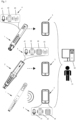
- Fig.1 depicts three variants of a medical injection monitoring and patient support system, each variant comprising an injection device 1, an electronic unit 4 and a mobile device 3 such as a smartphone or tablet device running a dedicated application program; or a laptop computer configured accordingly.
- the mobile device of each variant is adapted to interact with a respective patient 31 as well as a remote server, cloud based computing facility, or expert system 32.
- an electronic unit 4 is embedded, or incorporated, in the injection device.
- the electronic unit is part of an electronic module 2 that in turn is detachably mounted on the injection device.
- the electronic unit is part of the mobile device placed near the injection device.
- the electronic unit comprises a microphone 41, a processing unit 42 and a transmitter unit 43 for wireless transmission of data about the injection progress via Bluetooth Low Energy (BTLE) or equivalent short or near range wireless communication technology to the mobile device as indicated by the dashed horizontal arrows.
- the electronic unit includes, or is at least conceptually made up of, specific hardware elements or capabilities of the mobile device. Such elements include a microphone, processing unit, and data storage unit 44, which are shared by the mobile device for the purpose of the present invention. As depicted, the built-in microphone of the mobile device captures sound waves generated by the injection device.
- BTLE Bluetooth Low Energy
- Fig.2 and Fig.4 depict in more detail a first and second embodiment of the specific monitoring system of aforementioned variant two, with the electronic unit comprised in an electronic module 2.
- the pen-shaped injection device 1 has an elongate housing 10 essentially symmetric around a main axis.
- the electronic module has an elongate and hollow module housing 20 with a tubular sleeve forming a cavity or inner space adapted to an outer shape of the device housing, such that the injection device may be slidably inserted into the cavity.
- Included in the module housing is a lock/release mechanism to secure the attachment of the electronic module to the injection device in order to protect against unintended detachment.
- a detachable, reusable electronic module preferably is adapted for a sustained use during an intended lifetime, with corresponding requirements including a cleanable and waterproof, at least splash water protected, module housing.
- the module housing may be ergonomically shaped or designed to accommodate patient-specific usability requirements and to facilitate seizure of the injection device by the patient.
- the module housing has a cavity adapted to the elongate device housing such that, in the attached state, the electronic module essentially surrounds the injection device over at least a substantial part of the elongate injection device housing, such that the user exclusively seizes and holds the module housing and not the device housing in the attached state.
- a reliable locking mechanism prevents against axial movement of the module relative to the injection device, specifically during removal of the needle protective cap or the device cap, and during needle insertion.
- the elongate module housing may be designed to increase usability and provide a better grip by shaping the external surface in a convex manner with distal and/or proximal module housing end sections 20d of increased diameter to facilitate a transfer of axial force from the user to the device.
- the increased diameter gives rise to some toroidal volume that may be used to accommodate the electronic unit.
- the particular injection device depicted in variant two of Fig.1 and in Fig.2 is an auto-injector as further describe below in connection with Fig.3 , comprising a cover sleeve 11a that is movable between a first position (shown in Fig.2 ) and a second, or retracted, position in which the cover sleeve has moved in a proximal direction to be hidden inside, or enclosed by, the device housing.
- a needle protective cap 10d mounted onto a distal end of the injection device in order to protect, e.g. during shipping, a needle 13b of the injection device, has to be removed prior to injection, in order to expose the cover sleeve.
- a syringe 13a is either held immovable in the housing of the auto-injector, or may translate within the housing to insert or retract the needle.
- the electronic module depicted in Fig.2 further has a rear, or proximal, part where the electronic unit with some or all electronic components as described below is preferably located.
- Connection and system status indicators 20b, 20c provide visual feedback about a connection status indicative of an established communication link to a mobile device, and about a device, module, or process status including for instance an availability of battery power, a readiness of communication means, an attached/detached status of the electronic module and the injection device, or a progress of an ongoing injection process.
- the module housing has openings 20a that match with windows 10a of the injection device, which in turn allow for visual inspection of a substance comprised in the injection device.
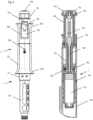
- Fig.3 depicts a sequence 3a to 3e of longitudinal sections of an injection device corresponding to successive operational steps as already described in EP 2781230 .
- the sections depicted are somewhat distorted in a transverse direction for the sake of legibility, and therefore not to scale.
- the injection device has a device housing 10 closed off by an end cap 10b, and a syringe holder part for accommodating a pre-filled syringe 13a with a needle 13b at a distal end.
- the injection device also includes a cover sleeve 11a that laterally surrounds the needle in the initial position after removal of a needle protective cap as seen in view 3a and in a final position after removal of the device from the injection site as seen in view 3e.
- a piston rod 16a transmits force from a drive means onto a piston comprised in the syringe for dispensing or expelling a liquid through the needle.
- An injection spring 16b serving as drive means and energy storage is pre-tensioned in an initial state between the piston rod 16a and a click pin.
- the click pin consists of a guide pin 17a arranged within the injection spring, and flexible release snap arms 17b connected to the guide pin via a proximal click pin end surface 17c. The latter also serves as a Start-of-Injection Sol signaling element.
- inner cams 17d at the distal end of the snap arms engage in indentations or openings of the piston rod to prevent a relative movement of piston rod and click pin.
- cover sleeve When the injection device is pressed onto an injection site the cover sleeve is axially displaced in proximal direction, i.e. in the direction of the horizontal arrow between views 3a and 3b. This retracting movement of the cover sleeve is transferred to a rigid locking sleeve 18 and further to a linear cover sleeve spring 11b with first and second spring base 11c, 11d, which is thus compressively charged, strained or tensioned.
- An End-of-Injection EoI signaling element, or end click sleeve 12 is provided adjacent to second cover spring base 11d.
- Views 3a to 3e depict in detail the various states of the injection device, starting with an initial state in view 3a in which the cover sleeve spring 11b is least charged or tensioned.
- View 3b depicts the state after insertion of the needle 13b into the skin of a patient, with the cover sleeve retracted and the cover sleeve spring 11b being compressed accordingly.
- the compression of the cover sleeve spring is represented by a displacement of a first base 11c of the cover sleeve between a first position (indicated by vertical line A1) and a second position (indicated by vertical line A2).
- the end click sleeve 12 In an initial part of the injection spring expansion the end click sleeve 12 is displaced in distal direction by another short distance under the effect of the relaxing injection spring, which in turn causes an additional compressive tensioning of the cover sleeve spring.
- the end-click sleeve moving At the end of the drug expel operation, the end-click sleeve moving is released to move in proximal direction under the force of the expanding cover sleeve spring.
- the end click sleeve After another short distance indicated by the horizontal arrow between views 3c and 3d, the end click sleeve abuts and generates an EoI click sound.
- the cover sleeve and the lock sleeve move in distal or forward direction under the force of the expanding cover sleeve spring.
- This axial displacement triggers a rotation of the locking sleeve which results in a cam, protrusion, or other guide element of the locking sleeve or the housing to abut and to line up at a step of the housing or of the locking sleeve, respectively.
- the cover sleeve is locked against further retraction.
- the abutment of the locking sleeve at the end of the rotation, or at the end of a short linear displacement following the rotation, generates a distinctive lock click sound.
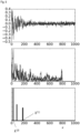
- Fig.5 depicts sample sounds recorded with a smartphone from an auto-injector. It is evident that the three distinct injection events give rise to distinct acoustic signatures.
- the particular injection device depicted in Fig.4 is a variable dose injection device 1 with a dose dialing facility as amply described for instance in EP 2812055 .
- the housing 10 forms the base of the pen-shaped injection device and is fixed to a carpule holder 10c containing a carpule or cartridge 13c by means of a snap connection. Dosing and delivery components are at least partially arranged in the housing.
- An indicator sleeve 14a is rigidly inserted into the housing 10 and has an internal thread, to which a thread on an outer surface of a dosing sleeve 14b is engaged.
- the rotary dosing knob 14c for enabling the user to adjust a dose is arranged on the proximal end of the dosing sleeve.
- the dosing sleeve features markings in the form of numbers on its outer surface.
- the adjusted dose is displayed in the window 10a.
- a discharge button 14d is snapped on the dosing sleeve in such a way that the discharge button can slightly move axially relative to the dosing sleeve and is freely rotatable.
- a reusable electronic module 2 has been mounted or fastened to the injection device housing 10 as depicted in the left-hand part of Fig.4 .
- the module housing 20 is designed to be positioned on the injection device housing in such a way as to neither interfere with the dial-and-dose components nor obscure any display window or visual indicator of the device.
- the module housing has the shape of a tubular sleeve from which the injection device extends at both ends, and has a recess or cut-out 20a that matches with the window 10a.
- the electronic module excludes the presence of a mechanical sensor to mechanically detect a rotation angle or linear shift of a dosing knob or other externally accessible component of the injection device. Likewise, the electronic module excludes the presence of an optical sensor to read a dialed dose from a dialing sleeve.
- FIG.4 shows a longitudinal section through the variable dose injection device in an initial state, after dose selection but prior to removal of a device cap 10e.
- the section has been drawn with a scale and aspect ratio different from the one in the left-hand drawing.
- a coupling sleeve 15a is arranged coaxial to the dosing sleeve 14b. Close to its proximal end the coupling sleeve comprises an annular flange 15b that engages, via a distally oriented toothing comprising an exemplary number of twenty teeth evenly distributed about the circumference, with a complementary annular counterface of the dosing sleeve.
- a dosing click-spring 15c is arranged between the discharge button 14d and the coupling sleeve. Due to the snap-on connection between the discharge button and the dosing sleeve, the annular flange and the counterface are pressed against one another. Turning the dosing knob 14c of the dosing sleeve in a dose-increasing, clockwise dialing direction or in a dose-reducing, counter-clockwise corrective direction relative to the coupling causes the toothing of the counterface to slide over the toothing of the flange, repeatedly performing a slight axial motion back and forth motion that gives rise to a clicking sound and vibration burst at every tooth.
- the number of clicks is proportionate to the dosage volume, wherein preferably each click or vibration burst corresponds to a single dosage unit, such as an International Unit IU.
- a relative rotation between the coupling sleeve and the dosing sleeve is inhibited when the discharge button is manually pressed in the distal direction against the spring force.
- a sleeve-shaped threaded nut 16c is axially fixed in the housing and rotationally coupled to the coupling sleeve 15a.
- the threaded nut features a thread that is engaged with the external thread of a piston rod 16a.
- the piston rod is axially guided by a piston rod guide 10f of the device housing.
- the threaded nut is provided with a flexible arm 19a having one end solidly anchored in the threaded nut and carrying a tooth, or cam, at a second, free end of the arm.
- the tooth may radially move or flex in a plane perpendicular to the axis such that the distance between the tooth and the axis varies.
- the flexible arm is biased radially outward such that the tooth arranged thereon engages with a grating 10g on the inner side of the housing.
- the flexible arm, the tooth and/or the grating are shaped in such a way that the threaded nut can only rotate in a direction which results in a motion of the piston rod in the distal, dose-expelling direction. Since the threaded nut rotates relative to the housing during the discharge, the tooth of the flexible arm also rotates relative to the grating, which in turn generates a mechanical, i.e. acoustic and tactile discharge feedback signal to the user.
- a plurality of, such as two or four, flexible arms with corresponding teeth may be provided, wherein the grating is designed such that an exemplary number of twenty time-wise distinct flex-back movements of the flexible arm(s) take place in one turn of the threaded nut.
- Each flex-back movement generates a mechanical feedback indicative of a dosage unit, or fraction thereof, being expelled, and involves one or several of the flexible arms discharging to abut against a bottom part of the grating.
- Fig.6 depicts an alternative to the flexible arms of Fig.4 that likewise operates as a reverse lock ensuring that the threaded nut can only be rotated or turned relative to the housing in one direction.
- the threaded nut 16c On its distal end, the threaded nut 16c is surrounded by an annular toothed disk 19b.
- the toothed disk can be longitudinally displaced relative to the threaded nut, but is secured against rotating relative to the threaded nut and arranged coaxial thereto.
- the toothed disk comprises a toothing 19c with an exemplary number of twenty teeth evenly distributed over the circumference and protruding in distal direction.
- the toothing is advantageously realized asymmetrically such that a relative rotation between the toothed disk and the housing is possible in one direction and blocked in the other direction.
- the exemplary wedge-shaped toothing visible in Fig.3 translates the rotation of the toothed disk into a combined axial and rotational movement, with tangential force components leading to a torque on the device housing that may be determined and exploited independently from the axial injection force component.
- Fig.7 is a flowchart illustrating a streamlined method of monitoring an injection process according to the invention.
- a small number N (j) of model parameters ⁇ (j) are determined for each of the reference sounds as detailed in the following, and stored for subsequent repeated use in a memory of the electronic unit.
- a representative number of, for instance, ten to twenty reference sound recordings per injection event may be exploited in order to obtain model parameters incorporating a minimum unavoidable variance in click sound generation.
- the preparatory steps may be executed in a controlled environment with minimal background noise, with specialized equipment or with the electronic unit that will be subsequently used during the recurring tracking steps. Updates of the model parameters may be performed as needed and deemed suitable.
- model parameters may be synthesized, i.e. derived from simulated operation of the sound generating means with known or assumed elastic properties, or from other heuristic methods.
- step S6 a first, second, and third match measure LLR (j) indicative of a match of the sample sound with the first, second, and third reference sound, respectively, is determined, based solely on the three sets of model parameters ⁇ (j) and the most recent sample sound data file y.
- the three match measures are determined at a same time, possibly one after the other and hence not necessarily strictly in parallel, such that they are ultimately available for relative comparison.
- LSS Linear State Space
- the model dimension n is a parameter that may be tuned in the algorithm.
- the model parameters ⁇ ( A, ⁇ ⁇ 2 , ⁇ Z 2 ) are unknown and have to be estimated.
- EM Expectation Maximization
- the state matrix A is constrained to have block-Jordan form, i.e. its only non- zero entries are the 2 ⁇ 2-Jordan-blocks on the diagonal.
- the decay factors of each state matrix may be scaled, in particular increased by a common factor, in order to improve the approximation of the original reference sound data.
- Fig.8 depicts an exemplary click reference sound (top), and a model waveform (bottom) reconstructed from the model parameters of a Linear State Space (LSS) Model as estimated from the original reference sound.
- LSS Linear State Space
- ⁇ j , X 0 0 This quantity is the ratio of the likelihood of the hypothesis that the injection event j as represented by its reference sound parameters ⁇ (j) is present in, or at the origin of, the sample sound y at time k and the likelihood of the hypothesis that there is only noise in the sample sound signal.
- the algorithm determines a maximum LLR ⁇ (j) at max-time k ⁇ (j) for each of at least two candidate injection events j , and identifies the injection event with the highest maximum LLR ⁇ as the true originator of the sample sound being investigated.
- a corresponding identifier j * together with a timestamp t y of the sample sound and optionally the highest maximum LLR* are retained for further evaluation or transmission, while the sample sound data is discarded.
- the maximum LLR of injection event No. 3 a cover sleeve locking event, is preponderant and the device event at the origin of the sample sound thus identified as a cover sleeve locking.
- the number N (j) of the above model parameters depends on, or includes, the dimension or rank of the LSS model and of the corresponding state matrix A (j) . This number does not have to be identical, for the purpose of the subsequent recurring calculation steps, for all injection events considered, and may in fact be chosen dependent on the injection event. Restricting the number of model parameters to an optimized minimum reduces storage and processing power requirements.
- a pre-determined number of Jordan blocks and/or corresponding frequencies ⁇ i are estimated initially from the reference sound based on established model estimation techniques. Subsequently, the estimated frequencies are analyzed, and a subset thereof is selected. In particular, the frequencies coinciding with peaks of a Discrete Fourier Transform (DFT) of the reference sound, or otherwise dominant frequencies may be chosen.
- DFT Discrete Fourier Transform
- the dedicated electronic unit includes a microphone, a processor unit including microprocessor or microcontroller elements suitably configured and physically mounted on Printed Circuit Boards, an antenna for wireless communication preferably according to the Bluetooth Low Energy (BLE) standard, and a power source or energy storage such as a battery, with all constituents being communicatively interconnected as needed via wired connections.
- BLE Bluetooth Low Energy
- the microprocessor units may include an analog-to-digital converter for preparing a digital sensor output signal, an evaluation unit for evaluating and consolidating sensor output signals from different sensors and/or with distinct time-stamps and for preparing consolidated information, a data storage or event recording unit for storing dynamic injection process information as well as unique identification data of a user, and a communication unit for transmitting and receiving wireless signals via the antenna.
- the wireless communication between the electronic unit and the mobile device may be subject to several features of the Bluetooth LE Core Specification that cover the encryption, trust, data integrity and privacy of the user's data. These features include advanced out-of-band pairing where the electronic unit and the mobile device involved in the communication exchange their identity information to set up trust and get the encryption keys ready for the future data exchange, or the ability to send authenticated data over an unencrypted transport between two devices with a trusted relationship.
- the electronic unit may also include a timer and/or real time clock to provide absolute or relative clock information as needed for time-stamping of injection events or timing of a thermal equilibration process following retrieval of the injection device from a refrigerator.
- the power source or energy storage may be rechargeable, and to that end may include a USB connector, or be adapted for wireless power transfer from a docking station.
- the docking station may accommodate the injection device, the electronic module, or the injection device together with the attached electronic module.
- the electronic unit specifically for use in conjunction with an injection device for repeated delivery of small amounts of a drug from a container that is to be stored in a cooled place between the injections, is itself adapted to be stored in a refrigerator at an exemplary cooling temperature of between 2°C and 12°C.
- the electronic unit may then be activated from stand-by upon removal from the refrigerator, e.g. by measuring a temperature exceeding a limit temperature.
- the electronic module may alternatively be activated or woken up from an idle state by a passive switching means responsive to a sustained change in temperature or illumination to which the injection device or the electronic module is exposed upon removal from the fridge.
- the passive switching means does not require any energy while placed in the refrigerator, and thus contributes to extended battery use.
- a shape memory alloy based electrical contact switch that is activated at a threshold temperature between the temperature of the refrigerator and room temperature may be used, or a photovoltaic cell designed to activate the processing unit and battery power supply upon exposure to daylight.
- the electronic unit may be equipped with, or connected to, additional reading units, such as an optical barcode reader for one or two-dimensional (QR) barcodes, or an electromagnetic Radio-Frequency IDentification (RFID) reader for identifying passive RFID tags containing electronically stored information.
- additional reading units such as an optical barcode reader for one or two-dimensional (QR) barcodes, or an electromagnetic Radio-Frequency IDentification (RFID) reader for identifying passive RFID tags containing electronically stored information.
- the barcode or RFID tag is attached to a container such as a syringe or carpule having been or being inserted in the injection device, and representing a lot or batch number or otherwise indicative of a drug comprised in the container.
- An electronic unit as part of a detachable electronic module may also employ the barcode or RFID reader to identify the injection device to which the module has been or is being attached.
- the electronic unit of the module may include a Near-Field Communication (NFC) unit for receiving an identifier or serial number transmitted by the injection device.
- NFC Near-Field Communication
- a processing unit adapted to receive an identification of the injection device, either manually from a user or via the aforementioned reading units, may proceed to selecting the corresponding reference sounds or model parameters from a multi-injection-device reference sound collection or storage.
- data upload may occur instantaneously and individually after each identified injection event. Data upload may also occur only following injection process completion and include consolidated information about the entire injection process.
- the mobile device With the mobile device being placed within visual and/or audible reach of the user, it may provide real-time Instructions for Use, guiding the user through the successive steps of a single injection event, and providing additional imminent feedback based on historical information. Visually impaired users may benefit from a kind of enlarged display enabled by the mobile device when duplicating information of a display of the mobile device.
- the mobile device not only acts as a user interface providing information to a user that mirrors or complements the status information generated by the electronic device itself, but also acts as a gateway to a cloud-based and secure data server and data evaluation facility.
- the data may be uploaded directly to a stationary receiver, for evaluation by an expert system and/or storage in a cloud computing environment. Such upload may take place by incorporating standard cellular mobile phone, e.g. GSM, or forthcoming low-power long range wireless communication technologies into the electronic module.
- Exemplary data recorded by the electronic module and subsequently or occasionally transmitted to the mobile device for storage or further dissemination includes at least a timing and a quality information of an injection event.
- Basic timing information such as time and date may be complemented by an indication of the injection site, i.e. to which body part of the patient the drug has been injected.
- the mobile device may accept manually entering the injection site information, possibly along with a self-appraisal of patient well-being or therapy outcome.
- Basic quality information includes an indication whether the injection was performed correctly or whether a deviation occurred from the correct intended usage.
- the quality information preferably comprises an indication about the deviation observed, including an interruption of the injection as caused by removal of the injection device from the injection site during injection, or a short holding time as caused by removal of the injection device from the injection site before lapse of a holding time after drug expelling.
- ICT related information such as a network address or identifier of the injection device, the electronic module, and/or the mobile device as well as information on the communication network(s) employed by the mobile device may be appended to the injection data at any stage of the transmission.
- the mobile device has to be set up initially by installing and configuring a smartphone application program and by duly identifying and enrolling the user, such as by means of a patient onboarding card conveying, by means of NFC or optical barcodes, all relevant data to the mobile device.
- the mobile device may then provide assistance, support and/or guidance to the user, such as advising about counter measures in case a deviation is detected, informing the user about drug expiration dates, and providing interactive and/or animated instructions for use corresponding to all stages of the injection process.
- the complete injection process support may commence with a reminder function supporting the user to remember when to perform an injection according to a prescribed therapy plan, continue with the timing of a thermal equilibration process following retrieval of the injection device from a refrigerator, a provision of instructions for attaching the electronic module and removing a needle protective cap from the injection device, suggesting an injection site e.g. different from the last injection site, monitoring the drug administration, and end with a provision of instructions for detachment of the electronic module and disposal of the injection device.
- the user may also be alerted in case a residual volume of drug decreases below a threshold.
- the electronic unit or the mobile device may also notify the user about an immediately preceding inactivity shut-down of the unit, together with a warning that this may have led to the last injection process not having been registered correctly.
- the mobile device may also store the data transmitted by the electronic unit, specifically timing and a quality information of a sequence of injection events as a consolidated injection history, and occasionally forward this data to the optional remote server, cloud based computing facility, or expert system.
- monitoring data that has been collected by any kind of smart monitoring unit, including but not limited to the electronic unit according to the present invention, as Protected Health Information (PHI).
- PHI Protected Health Information
- patient adherence data is referred to as the monitoring data accumulated by the electronic unit, including records of time-stamped injection events, but possibly including a log or transcript of a bidirectional interaction between patient and electronic device, including in particular any feedback or recommendation provided to the user. Communication of such patient adherence data from a mobile device or end-user gateway of the user to a remote site has to guarantee privacy and integrity of the data.
- communications containing PHI or equivalent patient adherence data and transmitted electronically over open networks have to be encrypted and protected from being intercepted by anyone other than the intended recipient.
- information technology systems receiving PHI must be protected from intrusion, and the identity of the intended recipient must be authenticated.
- Data integrity on the other hand may be increased by means of check sum, double-keying, message authentication, and digital signature.
- One option for storing patient adherence data in a computing cloud or other distributed data server structure comprises storing the data, on the one hand, in an encrypted format that restricts access to a holder of a particular key.
- data may be stored as anonymized cloud data, such that the patient may not be identified from the data.
- Anonymizing data may include location fuzzing, noise addition, permutation, k-anonymization, 1-diversity, or similar, and enable analysis of aggregated anonymized but otherwise unencrypted data by research institutions or health care stakeholders.
- personally identifiable patient adherence data may be shared directly with a trusted named doctor using standard public-key cryptography.
- Another option for storing patient adherence data in a computing cloud comprises uploading personally identifiable patient adherence data to the cloud where it is stored. Data transfer over networks is fully encrypted, and the stored data is accessible for detailed analysis by trusted experts (e.g., cloud-based doctor analysis). This option provides maximum flexibility with regards to analysis of personal data, and enables patients to use a web-based interface to access their data.
- a third option enabling a specialized healthcare data service provider to analyze PHI without violating the privacy of the patient resides on encrypting the patient adherence data according to a homomorphic encryption scheme, and sending the encrypted data to a data service provider. The latter may then evaluate the encrypted data and derive, or calculate, encrypted statistical or otherwise augmented information there from. The encrypted information is sent back to a trusted doctor of the patient, or to the end-user gateway embodying some medical expert knowledge, where it is decrypted and used for a refined diagnosis and/or adapted therapy.
- Fully homomorphic encryption schemes are compatible with an arbitrary number of additions and multiplications on encrypted data.
- all data processing functions comprising polynomial operations, including statistical functions such as the mean, standard deviation and logistical regressions, are compatible with homomorphic encryption schemes, and may be utilized by the healthcare data service provider.
Claims (15)
- Procédé de surveillance d'un processus d'injection exécuté au moyen d'un dispositif d'injection (1), comprenant- l'enregistrement d'un premier et d'un deuxième son de référence y(j)caractéristique, respectivement, d'un premier et d'un second événement d'injection j se produisant successivement pendant l'exécution de référence du processus d'injection ;- l'enregistrement, par un microphone (41) et une unité de traitement (42) connectée au microphone, pendant le processus d'injection à surveiller, d'un son échantillon y provenant d'un événement de dispositif, et la génération d'un horodatage indiquant un moment d'enregistrement du son d'échantillon ;- la détermination d'un premier et d'un second rapport de vraisemblance linéaire, LLR(j), de mesure de correspondance indiquant une correspondance du son d'échantillon avec le premier et le deuxième son de référence, respectivement ;- l'identification de l'événement de dispositif en tant que premier événement d'injection si la première mesure de correspondance dépasse la deuxième mesure de correspondance, et l'identification de l'événement de dispositif en tant que second événement d'injection si la deuxième mesure de correspondance dépasse la première mesure de correspondance ;- le stockage de l'horodatage conjointement avec un identifiant j* de l'événement d'injection identifié.
- Procédé selon la revendication 1, comprenant,- l'identification, à partir des premier et deuxième sons de référence, d'un premier et d'un second ensemble θ(j) de paramètres de modèle respectifs, et- la détermination des première et deuxième mesures de correspondance sur la base du premier et du second ensemble de paramètres de modèle, respectivement.
- Procédé selon la revendication 2, dans lequel un nombre N(1)de paramètres dans le premier ensemble de paramètres de modèle est différent d'un nombre N(2) de paramètres dans le second ensemble.
- Procédé selon la revendication 2, comprenant- la génération, à partir du son d'échantillon, d'un signal à temps discret y avec un nombre K de points de données, chaque point de données comprenant le temps k et les données correspondantes yk ;- la détermination, pour chaque point de données du signal à temps discret, d'une mesure de correspondance locale entre les données correspondantes yk du signal à temps discret et une évaluation du premier ensemble θ (l)de paramètres de modèle au temps k, et- la détermination de la première mesure de correspondance en tant que mesure de correspondance locale maximale.
- Procédé selon la revendication 2, dans lequel les paramètres de modèle comportent une fréquence ω i et un facteur de décroissance ρid'une matrice A de rotation de mise à l'échelle d'un modèle d'espace d'état linéaire du premier et du deuxième son de référence.
- Procédé selon l'une des revendications 1 à 5, dans lequel le premier événement d'injection est un début d'un processus d'expulsion de médicament signalé par un clic de début d'injection ; Sol ; et le second événement d'injection est une fin du processus d'expulsion de médicament signalée par un clic de fin d'injection, Eol, le procédé comprenant en outre- l'identification de l'événement de dispositif en tant que début d'un processus d'expulsion de médicament,- l'enregistrement, par la suite, d'un son d'échantillon supplémentaire provenant d'un événement de dispositif supplémentaire, la génération d'un horodatage indiquant un moment d'enregistrement de l'autre son d'échantillon, et l'identification de l'événement de dispositif supplémentaire en tant que fin du processus d'expulsion de médicament,- l'évaluation d'un retard temporel entre les horodatages de la fin et du début du processus d'expulsion de médicament pour conclure à une exécution du processus d'expulsion de médicament réussie.
- Procédé selon la revendication 6, dans lequel le dispositif d'injection est un auto-injecteur avec un ressort d'injection pour expulser une dose fixe de médicament à partir d'une seringue (13a) incluse dans le dispositif d'injection, et avec un manchon de couvercle (11a) sollicité par un ressort de manchon de couvercle pour protéger une aiguille de la seringue, le procédé comprenant- l'enregistrement d'une troisième caractéristique sonore de référence du manchon de couvercle étant verrouillé dans une position de protection d'aiguille ;- l'enregistrement, par le microphone et l'unité de traitement, pendant le processus d'injection à surveiller, d'un son d'échantillon suivant provenant d'un événement de dispositif suivant, et la génération d'un horodatage indiquant un moment d'enregistrement du son d'échantillon suivant ;- la détermination d'une première, d'une deuxième et d'une troisième mesure de correspondance indiquant une correspondance du son d'échantillon suivant avec les premier, deuxième et troisième sons de référence, respectivement ;- l'identification de l'événement de dispositif suivant en tant que verrouillage de manchon de couvercle dans une position de protection si la troisième mesure de correspondance dépasse la première et la deuxième mesure de correspondance,- l'évaluation d'un retard temporel entre l'horodatage de l'événement de verrouillage de manchon de couverture et un horodatage de la fin du processus d'expulsion de médicament pour conclure à un temps de maintien suffisant.
- Procédé selon l'une des revendications 1 à 5, dans lequel le dispositif d'injection est un dispositif d'injection à dose variable générant des clics de réglage et d'expulsion, dans lequel le premier événement d'injection est un événement de réglage d'unité de dosage signalé par un clic de réglage, et le second événement d'injection est un événement d'expulsion d'unité de dosage signalé par un clic d'expulsion, le procédé comprenant- l'identification de chacun d'une série d'événements de dispositif en tant qu'événement d'expulsion d'unité de dosage,- le comptage du nombre d'événements d'expulsion d'unité de dosage dans la série pour déterminer une dose expulsée.
- Procédé selon l'une des revendications 6 à 8, comprenant- la dérivation, à partir d'une pluralité d'horodatages stockés et d'identifiants d'événement d'injection, d'informations d'injection consolidées concernant le processus d'injection comportant une information de qualité du processus d'injection, et- la transmission, par une unité de communication sans fil (43) connectée à l'unité de traitement, des informations d'injection consolidées à un dispositif mobile (31).
- Unité électronique comprenant un microphone (41) et une unité de traitement (42) connectée au microphone, configurée pour coopérer avec un dispositif d'injection générant un son de clic pendant un processus d'injection, l'unité étant configurée pour- enregistrer et horodater, par le microphone et l'unité de traitement, pendant le processus d'injection à surveiller, un son d'échantillon y provenant d'un événement de dispositif,- déterminer un premier et un second rapport de vraisemblance linéaire, LLR (j) , de mesure de correspondance indiquant une correspondance du son d'échantillon avec un premier et un deuxième son de référence y(j) caractéristique respectivement d'un premier et d'un second événement d'injection j se produisant successivement pendant une exécution de référence du processus d'injection, à partir d'un ensemble respectif de paramètres de modèle stockés dans l'unité électronique et identifiés à partir du son de référence correspondant ;- identifier l'événement de dispositif en tant que premier événement si la première mesure de correspondance dépasse la deuxième mesure de correspondance, et vice versa ;- stocker l'horodatage conjointement avec un identificateur de l'événement identifié.
- Unité électronique selon la revendication 10, caractérisée en ce que l'unité est intégrée dans un dispositif mobile, et en ce que le microphone et l'unité de traitement sont partagés avec le dispositif mobile, le dispositif mobile pouvant être placé à proximité du dispositif d'injection pour surveiller le processus d'injection.
- Unité électronique selon la revendication 10, caractérisée en ce que l'unité est intégrée au dispositif d'injection ou dans un module électronique avec un boîtier de module adapté pour être fixé de manière amovible au dispositif d'injection, et en ce qu'elle comporte deux microphones.
- Unité électronique selon la revendication 10, caractérisée en ce que l'unité est intégrée dans le dispositif d'injection ou dans un module électronique avec un boîtier de module adapté pour être fixé de manière amovible au dispositif d'injection, et en ce qu'elle comprend un indicateur d'état (20c) pour indiquer un état du système à un utilisateur, en particulier pour indiquer un laps de temps de maintien.
- Unité électronique selon la revendication 10, caractérisée en ce que l'unité est intégrée dans le dispositif d'injection ou dans un module électronique avec un boîtier de module adapté pour être fixé de manière amovible au dispositif d'injection, caractérisée en ce qu'elle comprend une unité de stockage de données (44) pour stocker au moins une information de temps et de qualité d'un événement d'injection, et une unité de communication sans fil (43) pour transmettre les informations stockées à un dispositif mobile (3).
- Programme informatique qui, lorsqu'il est exécuté par une unité de traitement d'un dispositif mobile pour surveiller un processus d'injection réalisé au moyen d'un dispositif d'injection, amène l'unité de traitement à fonctionner selon l'une des revendications 1 à 8.
Priority Applications (1)
| Application Number | Priority Date | Filing Date | Title |
|---|---|---|---|
| EP17163731.7A EP3381493B1 (fr) | 2017-03-30 | 2017-03-30 | Unité électronique pour dispositifs d'injection |
Applications Claiming Priority (1)
| Application Number | Priority Date | Filing Date | Title |
|---|---|---|---|
| EP17163731.7A EP3381493B1 (fr) | 2017-03-30 | 2017-03-30 | Unité électronique pour dispositifs d'injection |
Publications (2)
| Publication Number | Publication Date |
|---|---|
| EP3381493A1 EP3381493A1 (fr) | 2018-10-03 |
| EP3381493B1 true EP3381493B1 (fr) | 2023-06-07 |
Family
ID=58461137
Family Applications (1)
| Application Number | Title | Priority Date | Filing Date |
|---|---|---|---|
| EP17163731.7A Active EP3381493B1 (fr) | 2017-03-30 | 2017-03-30 | Unité électronique pour dispositifs d'injection |
Country Status (1)
| Country | Link |
|---|---|
| EP (1) | EP3381493B1 (fr) |
Families Citing this family (10)
| Publication number | Priority date | Publication date | Assignee | Title |
|---|---|---|---|---|
| EP3476417A1 (fr) * | 2017-10-31 | 2019-05-01 | Tecpharma Licensing AG | Surveillance de dispositifs d'injection jetables |
| SI3860687T1 (sl) | 2018-10-03 | 2022-10-28 | Eli Lilly And Company | Sistemi za zazanavanja stanja znotraj sestave naprave za vbrizganje |
| EP3734605A1 (fr) * | 2019-04-30 | 2020-11-04 | Ypsomed AG | Transmission sécurisée de données d'administration de médicaments |
| US11771842B2 (en) | 2019-05-09 | 2023-10-03 | Medicines360 | Syringes, syringe containers, kits and methods of use |
| JP2022554241A (ja) * | 2019-10-28 | 2022-12-28 | サノフイ | 薬物送達デバイスの補助デバイスおよびリマインダシステム |
| JP2023502917A (ja) * | 2019-11-14 | 2023-01-26 | サノフイ | 薬物送達デバイスの無線データ通信アクセサリと外部デバイスの間の通信の保護 |
| EP3974012A1 (fr) * | 2020-09-29 | 2022-03-30 | Ypsomed AG | Identification d'événement d'amorçage dans des dispositifs de distribution |
| WO2022212227A1 (fr) * | 2021-03-31 | 2022-10-06 | Amgen Inc. | Système de mesure de durée d'injection basé sur la détection de son pour dispositifs d'administration de médicament |
| EP4326364A1 (fr) * | 2021-04-23 | 2024-02-28 | Sanofi | Module de codeur électronique et dispositif d'administration de médicament comprenant celui-ci |
| CN117138165B (zh) * | 2023-10-27 | 2024-01-23 | 江苏万海医疗器械有限公司 | 预制物料推送装置、输送器以及使用方法 |
Citations (1)
| Publication number | Priority date | Publication date | Assignee | Title |
|---|---|---|---|---|
| WO2016118736A1 (fr) * | 2015-01-23 | 2016-07-28 | Becton Dickinsonand Company | Procédé et dispositif pour capturer un événement de réglage de dose |
Family Cites Families (8)
| Publication number | Priority date | Publication date | Assignee | Title |
|---|---|---|---|---|
| JP5183620B2 (ja) | 2006-03-20 | 2013-04-17 | ノボ・ノルデイスク・エー/エス | 機械的薬剤投与デバイス用の電子モジュール |
| EP2753387B1 (fr) | 2011-09-08 | 2018-05-30 | Sanofi-Aventis Deutschland GmbH | Procédé et dispositif de surveillance pour une opération de surveillance d'un dispositif d'administration de médicaments |
| CH703993A2 (de) | 2012-02-09 | 2012-03-15 | Tecpharma Licensing Ag | Injektionsgerät zur Verabreichung oder Förderung von fluidem Produkt. |
| US10283014B2 (en) | 2012-04-04 | 2019-05-07 | Jbcb Holdings, Llc | Smart packaging and display system |
| WO2014064691A2 (fr) * | 2012-10-23 | 2014-05-01 | Insuline Medical Ltd. | Dispositif, système et procédé de suivi d'administration de médicament |
| EP2781230B1 (fr) | 2013-03-22 | 2019-08-21 | TecPharma Licensing AG | Dispositif de distribution de substances avec dispositif de signal |
| JP2016526471A (ja) | 2013-07-12 | 2016-09-05 | オシラリ リミテッド ライアビリティ カンパニー | 音声に基づく薬物送達モニター |
| US10795973B2 (en) | 2014-10-03 | 2020-10-06 | Noble International, Inc. | Medicament training device and system |
-
2017
- 2017-03-30 EP EP17163731.7A patent/EP3381493B1/fr active Active
Patent Citations (1)
| Publication number | Priority date | Publication date | Assignee | Title |
|---|---|---|---|---|
| WO2016118736A1 (fr) * | 2015-01-23 | 2016-07-28 | Becton Dickinsonand Company | Procédé et dispositif pour capturer un événement de réglage de dose |
Also Published As
| Publication number | Publication date |
|---|---|
| EP3381493A1 (fr) | 2018-10-03 |
Similar Documents
| Publication | Publication Date | Title |
|---|---|---|
| EP3381493B1 (fr) | Unité électronique pour dispositifs d'injection | |
| US11406768B2 (en) | Electronic module for monitoring injection devices | |
| KR102077901B1 (ko) | 약물 전달 장치 | |
| TWI608851B (zh) | 藥物輸送裝置 | |
| US20210085880A1 (en) | Click event identification in delivery devices | |
| CN107073208B (zh) | 药剂输送装置 | |
| US20180236185A1 (en) | Recording Unit | |
| US9327077B2 (en) | Medical injector with compliance tracking and monitoring | |
| CN105102024B (zh) | 适合于将剂量组合的记录设备 | |
| TWI600597B (zh) | 用於處理醫療廢物的裝置 | |
| US10460836B2 (en) | Medical device system and method for establishing wireless communication | |
| US11534556B2 (en) | Monitoring an injection process | |
| US20220051778A1 (en) | Secure drug delivery data transmission | |
| KR20160094401A (ko) | 의료 장치 연결 스테이션 | |
| KR20160146469A (ko) | 임상시험 관리 장치 및 방법 | |
| EP3773823A1 (fr) | Estimation d'état pour des systèmes d'administration de médicament | |
| CN110913928A (zh) | 用于数字监控自动注射器的使用情况以改善依从性、远程患者监控以及坚持性的设备附件 | |
| KR101958067B1 (ko) | 펜형 주사장치의 범용 장착형 투입량 측정 및 관리 시스템 | |
| US20230191036A1 (en) | Management platform for intelligent injection devices | |
| WO2019193061A1 (fr) | Fonction de sécurité de transmission de données | |
| US20230207092A1 (en) | Priming event identification in delivery devices | |
| KR20190042830A (ko) | 펜형 주사장치의 범용 장착형 투입량 측정 및 관리 시스템 | |
| US20220133282A1 (en) | Secure device for delivering medications |
Legal Events
| Date | Code | Title | Description |
|---|---|---|---|
| PUAI | Public reference made under article 153(3) epc to a published international application that has entered the european phase |
Free format text: ORIGINAL CODE: 0009012 |
|
| STAA | Information on the status of an ep patent application or granted ep patent |
Free format text: STATUS: THE APPLICATION HAS BEEN PUBLISHED |
|
| AK | Designated contracting states |
Kind code of ref document: A1 Designated state(s): AL AT BE BG CH CY CZ DE DK EE ES FI FR GB GR HR HU IE IS IT LI LT LU LV MC MK MT NL NO PL PT RO RS SE SI SK SM TR |
|
| AX | Request for extension of the european patent |
Extension state: BA ME |
|
| STAA | Information on the status of an ep patent application or granted ep patent |
Free format text: STATUS: REQUEST FOR EXAMINATION WAS MADE |
|
| 17P | Request for examination filed |
Effective date: 20190403 |
|
| RBV | Designated contracting states (corrected) |
Designated state(s): AL AT BE BG CH CY CZ DE DK EE ES FI FR GB GR HR HU IE IS IT LI LT LU LV MC MK MT NL NO PL PT RO RS SE SI SK SM TR |
|
| STAA | Information on the status of an ep patent application or granted ep patent |
Free format text: STATUS: EXAMINATION IS IN PROGRESS |
|
| 17Q | First examination report despatched |
Effective date: 20191204 |
|
| STAA | Information on the status of an ep patent application or granted ep patent |
Free format text: STATUS: EXAMINATION IS IN PROGRESS |
|
| RAP1 | Party data changed (applicant data changed or rights of an application transferred) |
Owner name: YPSOMED AG |
|
| STAA | Information on the status of an ep patent application or granted ep patent |
Free format text: STATUS: EXAMINATION IS IN PROGRESS |
|
| TPAC | Observations filed by third parties |
Free format text: ORIGINAL CODE: EPIDOSNTIPA |
|
| GRAP | Despatch of communication of intention to grant a patent |
Free format text: ORIGINAL CODE: EPIDOSNIGR1 |
|
| STAA | Information on the status of an ep patent application or granted ep patent |
Free format text: STATUS: GRANT OF PATENT IS INTENDED |
|
| INTG | Intention to grant announced |
Effective date: 20230113 |
|
| GRAS | Grant fee paid |
Free format text: ORIGINAL CODE: EPIDOSNIGR3 |
|
| GRAA | (expected) grant |
Free format text: ORIGINAL CODE: 0009210 |
|
| STAA | Information on the status of an ep patent application or granted ep patent |
Free format text: STATUS: THE PATENT HAS BEEN GRANTED |
|
| AK | Designated contracting states |
Kind code of ref document: B1 Designated state(s): AL AT BE BG CH CY CZ DE DK EE ES FI FR GB GR HR HU IE IS IT LI LT LU LV MC MK MT NL NO PL PT RO RS SE SI SK SM TR |
|
| REG | Reference to a national code |
Ref country code: GB Ref legal event code: FG4D |
|
| REG | Reference to a national code |
Ref country code: CH Ref legal event code: EP Ref country code: AT Ref legal event code: REF Ref document number: 1573041 Country of ref document: AT Kind code of ref document: T Effective date: 20230615 Ref country code: DE Ref legal event code: R096 Ref document number: 602017069342 Country of ref document: DE |
|
| REG | Reference to a national code |
Ref country code: LT Ref legal event code: MG9D |
|
| REG | Reference to a national code |
Ref country code: NL Ref legal event code: MP Effective date: 20230607 |
|
| PG25 | Lapsed in a contracting state [announced via postgrant information from national office to epo] |
Ref country code: SE Free format text: LAPSE BECAUSE OF FAILURE TO SUBMIT A TRANSLATION OF THE DESCRIPTION OR TO PAY THE FEE WITHIN THE PRESCRIBED TIME-LIMIT Effective date: 20230607 Ref country code: NO Free format text: LAPSE BECAUSE OF FAILURE TO SUBMIT A TRANSLATION OF THE DESCRIPTION OR TO PAY THE FEE WITHIN THE PRESCRIBED TIME-LIMIT Effective date: 20230907 Ref country code: ES Free format text: LAPSE BECAUSE OF FAILURE TO SUBMIT A TRANSLATION OF THE DESCRIPTION OR TO PAY THE FEE WITHIN THE PRESCRIBED TIME-LIMIT Effective date: 20230607 |
|
| REG | Reference to a national code |
Ref country code: AT Ref legal event code: MK05 Ref document number: 1573041 Country of ref document: AT Kind code of ref document: T Effective date: 20230607 |
|
| PG25 | Lapsed in a contracting state [announced via postgrant information from national office to epo] |
Ref country code: RS Free format text: LAPSE BECAUSE OF FAILURE TO SUBMIT A TRANSLATION OF THE DESCRIPTION OR TO PAY THE FEE WITHIN THE PRESCRIBED TIME-LIMIT Effective date: 20230607 Ref country code: NL Free format text: LAPSE BECAUSE OF FAILURE TO SUBMIT A TRANSLATION OF THE DESCRIPTION OR TO PAY THE FEE WITHIN THE PRESCRIBED TIME-LIMIT Effective date: 20230607 Ref country code: LV Free format text: LAPSE BECAUSE OF FAILURE TO SUBMIT A TRANSLATION OF THE DESCRIPTION OR TO PAY THE FEE WITHIN THE PRESCRIBED TIME-LIMIT Effective date: 20230607 Ref country code: LT Free format text: LAPSE BECAUSE OF FAILURE TO SUBMIT A TRANSLATION OF THE DESCRIPTION OR TO PAY THE FEE WITHIN THE PRESCRIBED TIME-LIMIT Effective date: 20230607 Ref country code: HR Free format text: LAPSE BECAUSE OF FAILURE TO SUBMIT A TRANSLATION OF THE DESCRIPTION OR TO PAY THE FEE WITHIN THE PRESCRIBED TIME-LIMIT Effective date: 20230607 Ref country code: GR Free format text: LAPSE BECAUSE OF FAILURE TO SUBMIT A TRANSLATION OF THE DESCRIPTION OR TO PAY THE FEE WITHIN THE PRESCRIBED TIME-LIMIT Effective date: 20230908 |
|
| PG25 | Lapsed in a contracting state [announced via postgrant information from national office to epo] |
Ref country code: FI Free format text: LAPSE BECAUSE OF FAILURE TO SUBMIT A TRANSLATION OF THE DESCRIPTION OR TO PAY THE FEE WITHIN THE PRESCRIBED TIME-LIMIT Effective date: 20230607 |
|
| PG25 | Lapsed in a contracting state [announced via postgrant information from national office to epo] |
Ref country code: SK Free format text: LAPSE BECAUSE OF FAILURE TO SUBMIT A TRANSLATION OF THE DESCRIPTION OR TO PAY THE FEE WITHIN THE PRESCRIBED TIME-LIMIT Effective date: 20230607 |
|
| PG25 | Lapsed in a contracting state [announced via postgrant information from national office to epo] |
Ref country code: IS Free format text: LAPSE BECAUSE OF FAILURE TO SUBMIT A TRANSLATION OF THE DESCRIPTION OR TO PAY THE FEE WITHIN THE PRESCRIBED TIME-LIMIT Effective date: 20231007 |
|
| PG25 | Lapsed in a contracting state [announced via postgrant information from national office to epo] |
Ref country code: SM Free format text: LAPSE BECAUSE OF FAILURE TO SUBMIT A TRANSLATION OF THE DESCRIPTION OR TO PAY THE FEE WITHIN THE PRESCRIBED TIME-LIMIT Effective date: 20230607 Ref country code: SK Free format text: LAPSE BECAUSE OF FAILURE TO SUBMIT A TRANSLATION OF THE DESCRIPTION OR TO PAY THE FEE WITHIN THE PRESCRIBED TIME-LIMIT Effective date: 20230607 Ref country code: RO Free format text: LAPSE BECAUSE OF FAILURE TO SUBMIT A TRANSLATION OF THE DESCRIPTION OR TO PAY THE FEE WITHIN THE PRESCRIBED TIME-LIMIT Effective date: 20230607 Ref country code: PT Free format text: LAPSE BECAUSE OF FAILURE TO SUBMIT A TRANSLATION OF THE DESCRIPTION OR TO PAY THE FEE WITHIN THE PRESCRIBED TIME-LIMIT Effective date: 20231009 Ref country code: IS Free format text: LAPSE BECAUSE OF FAILURE TO SUBMIT A TRANSLATION OF THE DESCRIPTION OR TO PAY THE FEE WITHIN THE PRESCRIBED TIME-LIMIT Effective date: 20231007 Ref country code: EE Free format text: LAPSE BECAUSE OF FAILURE TO SUBMIT A TRANSLATION OF THE DESCRIPTION OR TO PAY THE FEE WITHIN THE PRESCRIBED TIME-LIMIT Effective date: 20230607 Ref country code: CZ Free format text: LAPSE BECAUSE OF FAILURE TO SUBMIT A TRANSLATION OF THE DESCRIPTION OR TO PAY THE FEE WITHIN THE PRESCRIBED TIME-LIMIT Effective date: 20230607 Ref country code: AT Free format text: LAPSE BECAUSE OF FAILURE TO SUBMIT A TRANSLATION OF THE DESCRIPTION OR TO PAY THE FEE WITHIN THE PRESCRIBED TIME-LIMIT Effective date: 20230607 |
|
| PG25 | Lapsed in a contracting state [announced via postgrant information from national office to epo] |
Ref country code: PL Free format text: LAPSE BECAUSE OF FAILURE TO SUBMIT A TRANSLATION OF THE DESCRIPTION OR TO PAY THE FEE WITHIN THE PRESCRIBED TIME-LIMIT Effective date: 20230607 |
|
| REG | Reference to a national code |
Ref country code: DE Ref legal event code: R097 Ref document number: 602017069342 Country of ref document: DE |
|
| PLBE | No opposition filed within time limit |
Free format text: ORIGINAL CODE: 0009261 |
|
| STAA | Information on the status of an ep patent application or granted ep patent |
Free format text: STATUS: NO OPPOSITION FILED WITHIN TIME LIMIT |