EP3380739B1 - Procédé de fabrication d'un composant solide et composant solide - Google Patents
Procédé de fabrication d'un composant solide et composant solide Download PDFInfo
- Publication number
- EP3380739B1 EP3380739B1 EP16816184.2A EP16816184A EP3380739B1 EP 3380739 B1 EP3380739 B1 EP 3380739B1 EP 16816184 A EP16816184 A EP 16816184A EP 3380739 B1 EP3380739 B1 EP 3380739B1
- Authority
- EP
- European Patent Office
- Prior art keywords
- component
- rotation
- solid
- axis
- pockets
- Prior art date
- Legal status (The legal status is an assumption and is not a legal conclusion. Google has not performed a legal analysis and makes no representation as to the accuracy of the status listed.)
- Active
Links
- 239000007787 solid Substances 0.000 title claims description 96
- 238000004519 manufacturing process Methods 0.000 title claims description 32
- 238000005520 cutting process Methods 0.000 claims description 76
- 238000003754 machining Methods 0.000 claims description 38
- 238000000034 method Methods 0.000 claims description 25
- 238000005096 rolling process Methods 0.000 claims description 22
- 230000008878 coupling Effects 0.000 claims 1
- 238000010168 coupling process Methods 0.000 claims 1
- 238000005859 coupling reaction Methods 0.000 claims 1
- 238000012545 processing Methods 0.000 description 34
- 239000000463 material Substances 0.000 description 4
- 239000002184 metal Substances 0.000 description 4
- 229910052751 metal Inorganic materials 0.000 description 4
- 230000010363 phase shift Effects 0.000 description 4
- 239000011265 semifinished product Substances 0.000 description 4
- 230000007704 transition Effects 0.000 description 4
- 238000007790 scraping Methods 0.000 description 3
- 238000007730 finishing process Methods 0.000 description 2
- 229910000881 Cu alloy Inorganic materials 0.000 description 1
- CWYNVVGOOAEACU-UHFFFAOYSA-N Fe2+ Chemical compound [Fe+2] CWYNVVGOOAEACU-UHFFFAOYSA-N 0.000 description 1
- 229910000831 Steel Inorganic materials 0.000 description 1
- 238000013459 approach Methods 0.000 description 1
- 125000004122 cyclic group Chemical group 0.000 description 1
- 238000011161 development Methods 0.000 description 1
- 230000000694 effects Effects 0.000 description 1
- 238000005516 engineering process Methods 0.000 description 1
- 238000007654 immersion Methods 0.000 description 1
- 238000009434 installation Methods 0.000 description 1
- 239000013067 intermediate product Substances 0.000 description 1
- 230000014759 maintenance of location Effects 0.000 description 1
- 210000001331 nose Anatomy 0.000 description 1
- 238000012805 post-processing Methods 0.000 description 1
- 238000003672 processing method Methods 0.000 description 1
- 230000000630 rising effect Effects 0.000 description 1
- 239000010959 steel Substances 0.000 description 1
- 238000012549 training Methods 0.000 description 1
Images


Classifications
-
- F—MECHANICAL ENGINEERING; LIGHTING; HEATING; WEAPONS; BLASTING
- F16—ENGINEERING ELEMENTS AND UNITS; GENERAL MEASURES FOR PRODUCING AND MAINTAINING EFFECTIVE FUNCTIONING OF MACHINES OR INSTALLATIONS; THERMAL INSULATION IN GENERAL
- F16C—SHAFTS; FLEXIBLE SHAFTS; ELEMENTS OR CRANKSHAFT MECHANISMS; ROTARY BODIES OTHER THAN GEARING ELEMENTS; BEARINGS
- F16C33/00—Parts of bearings; Special methods for making bearings or parts thereof
- F16C33/30—Parts of ball or roller bearings
- F16C33/46—Cages for rollers or needles
- F16C33/4617—Massive or moulded cages having cage pockets surrounding the rollers, e.g. machined window cages
- F16C33/4623—Massive or moulded cages having cage pockets surrounding the rollers, e.g. machined window cages formed as one-piece cages, i.e. monoblock cages
- F16C33/4629—Massive or moulded cages having cage pockets surrounding the rollers, e.g. machined window cages formed as one-piece cages, i.e. monoblock cages made from metal, e.g. cast or machined window cages
-
- B—PERFORMING OPERATIONS; TRANSPORTING
- B23—MACHINE TOOLS; METAL-WORKING NOT OTHERWISE PROVIDED FOR
- B23B—TURNING; BORING
- B23B27/00—Tools for turning or boring machines; Tools of a similar kind in general; Accessories therefor
- B23B27/005—Geometry of the chip-forming or the clearance planes, e.g. tool angles
-
- B—PERFORMING OPERATIONS; TRANSPORTING
- B23—MACHINE TOOLS; METAL-WORKING NOT OTHERWISE PROVIDED FOR
- B23B—TURNING; BORING
- B23B5/00—Turning-machines or devices specially adapted for particular work; Accessories specially adapted therefor
- B23B5/36—Turning-machines or devices specially adapted for particular work; Accessories specially adapted therefor for turning specially-shaped surfaces by making use of relative movement of the tool and work produced by geometrical mechanisms, i.e. forming-lathes
-
- F—MECHANICAL ENGINEERING; LIGHTING; HEATING; WEAPONS; BLASTING
- F16—ENGINEERING ELEMENTS AND UNITS; GENERAL MEASURES FOR PRODUCING AND MAINTAINING EFFECTIVE FUNCTIONING OF MACHINES OR INSTALLATIONS; THERMAL INSULATION IN GENERAL
- F16C—SHAFTS; FLEXIBLE SHAFTS; ELEMENTS OR CRANKSHAFT MECHANISMS; ROTARY BODIES OTHER THAN GEARING ELEMENTS; BEARINGS
- F16C33/00—Parts of bearings; Special methods for making bearings or parts thereof
- F16C33/30—Parts of ball or roller bearings
- F16C33/46—Cages for rollers or needles
- F16C33/49—Cages for rollers or needles comb-shaped
- F16C33/494—Massive or moulded comb cages
- F16C33/495—Massive or moulded comb cages formed as one piece cages, i.e. monoblock comb cages
- F16C33/497—Massive or moulded comb cages formed as one piece cages, i.e. monoblock comb cages made from metal, e.g. cast or machined comb cages
-
- B—PERFORMING OPERATIONS; TRANSPORTING
- B23—MACHINE TOOLS; METAL-WORKING NOT OTHERWISE PROVIDED FOR
- B23P—METAL-WORKING NOT OTHERWISE PROVIDED FOR; COMBINED OPERATIONS; UNIVERSAL MACHINE TOOLS
- B23P15/00—Making specific metal objects by operations not covered by a single other subclass or a group in this subclass
- B23P15/003—Making specific metal objects by operations not covered by a single other subclass or a group in this subclass bearings
-
- B—PERFORMING OPERATIONS; TRANSPORTING
- B23—MACHINE TOOLS; METAL-WORKING NOT OTHERWISE PROVIDED FOR
- B23Q—DETAILS, COMPONENTS, OR ACCESSORIES FOR MACHINE TOOLS, e.g. ARRANGEMENTS FOR COPYING OR CONTROLLING; MACHINE TOOLS IN GENERAL CHARACTERISED BY THE CONSTRUCTION OF PARTICULAR DETAILS OR COMPONENTS; COMBINATIONS OR ASSOCIATIONS OF METAL-WORKING MACHINES, NOT DIRECTED TO A PARTICULAR RESULT
- B23Q27/00—Geometrical mechanisms for the production of work of particular shapes, not fully provided for in another subclass
Definitions
- the invention relates to a method for manufacturing a solid component with the features of claim 1 and a solid component which is manufactured by means of the method.
- Cages in rolling bearings are used to guide rolling elements and to space them apart.
- the cages are often ring-shaped and have windows in which the rolling elements are arranged.
- so-called solid cages are known as solid components, which are worked out from a solid semi-finished product using separating processes.
- the machining in particular leads to high manufacturing costs, since the windows are often milled out one after the other.
- the invention relates to a method for manufacturing a solid component.
- the solid component is manufactured from a solid semi-finished product by separating process steps.
- the solid component and / or the semi-finished product are preferably made of metal.
- the metal can be a steel material, but it is also possible for the solid component to consist of a non-ferrous metal, in particular a copper alloy.
- the solid component defines a component axis of rotation, the component axis of rotation being determined by the axis of rotation of the solid component during operation.
- the solid component has a plurality of pockets which are preferably regularly spaced apart from one another in the circumferential direction about the component axis of rotation. Intermediate areas, in particular webs, are preferably arranged between the pockets.
- the pockets each have a first and a second pocket side in the circumferential direction, which are formed by the adjacent intermediate region sides, in particular web sides.
- the pockets are designed as sack pockets or as through openings in the solid component. In particular, each pocket is delimited on the edge by two intermediate areas, in particular webs.
- a component blank is preferably produced from the semifinished product using a raw machining tool, the component blank having a plurality of raw pockets which are preferably separated or spaced apart from one another by intermediate raw regions, in particular raw webs.
- the component blank is designed in particular as an intermediate product.
- the component blank is designed in particular as a ring or cylinder or has at least one ring section or cylinder section, the raw pockets forming openings and / or passages in the radial direction in the ring or ring section.
- the raw bags are designed as raw sack bags.
- the intermediate raw areas, in particular raw webs are located at the positions which the intermediate areas, in particular webs, are arranged after further production steps.
- the number of intermediate raw areas, in particular raw webs corresponds to the later number of intermediate areas, in particular webs.
- the first pocket sides are in particular designed to be separating and / or cutting and / or cutting by means of a tool cutting edge.
- the training takes place in the final contour, so that the pocket sides formed can be used as intended without further post-processing steps.
- a first cycloid machining step the tool cutting edge is guided relative to the component blank along a first cycloid path.
- the tool cutting edge is guided relative to the component blank along the first cycloid path, the component blank rotating in a first component rotation direction about the component axis of rotation.
- first pocket sides are cut by means of the tool cutting edge.
- a rake angle of the tool cutting edge when manufacturing the first pocket sides is in the range from -15 ° to 0 °.
- the first pocket sides are not manufactured by means of "scraping".
- the tool cutting edge is particularly preferably guided contact-free to the second pocket sides or the regions of the raw pockets which subsequently form the second pocket sides.
- the component rotation direction is subsequently reversed and the component blank is rotated in a component counter direction.
- the second pocket sides are produced in the final contour by means of a further tool cutting edge, the tool cutting edge being guided along a second cycloid path in a second cycloid machining step relative to the component blank.
- the further tool cutting edge is guided in the second cycloid processing step relative to the component blank rotating about the component axis of rotation in the component counter-rotation direction along the second cycloid path for processing the raw pockets.
- the second pocket sides are cut by means of the further tool cutting edge and that a rake angle of the further tool cutting edge when producing the second pocket sides is in a range between -15 ° and 0 °.
- the second pocket sides are not manufactured by means of "scraping".
- the tool cutting edge is particularly preferably guided to the first pocket sides without contact.
- the rake angle is preferably defined by the angle between the material plane before the cut and the rake surface of the tool cutting edge minus 90 °.
- a cycloid path - also called a cyclic curve, wheel arch or roll curve - is preferably understood to mean a path that describes a circle point when a circle rolls on a guide curve.
- the guide curve is designed, for example, as a concentric circle around the component axis of rotation.
- the cycloid path is designed as an elongated cycloid path, the tool cutting edge being arranged outside the circle rolling on the guide curve.
- the cycloid track has loops at the tips as an extended cycloid track. The loops form the cutting path of the tool cutting edge in the component blank and thus define the geometrical shape of the pocket sides.
- the surface quality of the pocket sides on the one hand of the first or second pocket side is of the same height and, secondly, has a sufficient quality so that a finishing process can be omitted or the finishing process is provided by the first and second cycloid processing step.
- the first and second pocket sides are brought into a final shape by the first and second cycloid processing steps. It is thus possible to manufacture a solid component inexpensively using a cycloid processing method and at the same time to achieve a high surface quality and / or shape retention or a low tolerance.
- the method is divided into three steps, the raw pockets being introduced in a preliminary step, the first pocket sides being cut in a first cycloid machining step and the second pocket sides being cut in a second cycloid machining step. It can be provided that the raw pockets are inserted by means of roughing, the first and second sides of the pocket by means of finishing.
- the component blank in the first and / or in the second cycloid machining step, is rotated about the component axis of rotation and the tool cutting edge about a tool axis of rotation.
- the component axis of rotation and the tool axis of rotation are parallel to one another, but spatially offset or spaced apart by an infeed distance.
- the infeed distance between the component axis of rotation and the tool axis of rotation is changed in the course of the first and / or the second cycloid machining step.
- the component blank is rotated in one component rotation direction and the tool cutting edge in one tool rotation direction.
- the component blank is rotated in a component counter-rotating direction and the tool cutting edge in a tool counter-rotating direction, that is to say in the opposite direction.
- the first cycloid path is designed in the opposite direction to the second cycloid path. In this way, identical or at least similar cutting conditions can be achieved for the first and the second pocket side.
- the first cycloid orbit and the second cycloid orbit are preferably arranged out of phase with one another, but are particularly preferably identical in shape and / or in the course.
- the phase shift in particular by an offset angle around the component axis of rotation, ensures that only the first pocket side is manufactured, in particular cut, in the first cycloid machining step and the second pocket side remains contact-free and in the second Cycloid processing step only the second pocket side is manufactured, in particular is cut and the first pocket side remains contact-free.
- the pocket sides are machined into the component blank radially from the outside or radially from the inside.
- the tool cutting edge works from the outside inwards with respect to the component rotation axis
- the tool cutting edge works from the inside outwards, likewise with respect to the component rotation axis.
- the directions of rotation of the component blank and the tool cutting edge are preferably selected as follows: The tool cutting edge and the component blank rotate in opposite or opposite directions, provided that the tool cutting edge begins to cut on an outer circumference of the component blank.
- the tool cutting edge and the component blank rotate in the same direction or in the same direction, provided the component blank is ring-shaped and the tool cutting edge starts at an inner circumference of the component blank.
- the tool cutting edge and the further tool cutting edge have an angle of attack relative to a radial vector to the cage rotation axis as the component rotation axis. It is preferred that the angle of attack is designed differently in the first and in the second cycloid processing step. The different angle of attack ensures that the respective tool cutting edge can be cut in both cycloid machining steps or with the rake angle mentioned.
- the angles of attack with respect to the radial vector are particularly preferably of the same size, but the tool cutting edges are arranged mirror-symmetrically to the radial vector.
- the angle of attack can be changed from the first to the second cycloid machining step in different ways: On the one hand, it is possible for the tool cutting edge to be pivoted by 180 degrees around the radial vector of the tool rotation axis during the transition from the first cycloid machining step to the second cycloid machining step in order to form the further tool cutting edge. Alternatively, it is possible to use two different tool cutting edges, which are arranged, for example, axially offset along the tool axis of rotation. It is also possible Use tool changing system, which changes the tool cutting edges between the cycloid machining steps.
- the infeed distance is changed as a function of an axial position of the tool cutting edge relative to the cage blank.
- the infeed distance is particularly preferably changed as a function of the axial position of the tool cutting edge relative to the component blank such that the pockets are trapezoidal.
- the pockets are trapezoidal in a radial top view. The transition from rectangular pockets to trapezoidal pockets can thus be carried out in a simple manner by programming a corresponding production device and does not cause any further costs in the production of the solid component.
- the inclination and / or the inclination profile of the pocket sides in the radial direction to the component axis of rotation can also be designed differently for the first and the second pocket sides. If one looks at an end face of the pocket, in particular a floor area or a ceiling area in the axial direction, the boundaries of the end faces can be designed asymmetrically to one another in the circumferential direction. In particular, the transitions to the pocket sides can be trapezoidal and / or independent of one another.
- each of the pockets has two end faces and two pocket sides, at least one of the end faces being approximately trapezoidal, in particular trapezoidal, as viewed in the direction of the component axis of rotation, and / or the pocket sides, viewed in a radial plan view, are approximately trapezoidal, in particular trapezoidal.
- the raw pockets are introduced into the component blank by a pre-cycloid processing step as a rough processing step.
- a pre-cycloid processing step is, however, provided that both pocket sides of the raw webs are manufactured in the same pre-cycloid processing step. The reason for this is that the pocket sides are brought into the final shape anyway by the subsequent cycloid processing steps, so that no particularly high surface quality or manufacturing accuracy is required during the pre-cycloid processing step.
- the first cycloid path is phase-shifted in a first direction of rotation and the second cycloid path is phase-shifted in a direction opposite to the pre-cycloid path.
- the solid component is designed as a solid cage for a roller bearing.
- the roller bearing is preferably designed as a roller bearing and, in particularly preferred embodiments of the invention, as a tapered roller bearing.
- the solid cage defines a cage axis of rotation as the component axis of rotation.
- the solid cage has a plurality of webs as the intermediate regions, the pockets being arranged between the webs, the pockets being designed as receptacles of rolling elements of the rolling bearing.
- the solid cage can have exactly one circumferential row of webs or can also have two or more rows.
- the solid cage can optionally have side rings or intermediate rings, the webs connecting the side rings and / or intermediate rings in the axial direction. Side rings or intermediate rings and webs are integrally formed together.
- the webs each have a first and a second web side, which at the same time form the pocket sides, the web sides being designed to bear the rolling elements in the circumferential direction about the axis of rotation of the cage.
- the web sides have contact surfaces for the rolling elements. All first web sides point in a first circumferential direction and all second web sides in a second circumferential direction, which is designed as the opposite direction to the first circumferential direction. The web sides limit the webs in the circumferential direction.
- the raw pockets are at the position in the circumferential direction at which the pockets for receiving the rolling elements are arranged after the further method steps.
- the raw webs are each wider in the circumferential direction than the webs.
- Another object of the invention relates to a solid component, in particular a solid cage for a rolling bearing or a solid shaft, as described above, the solid component being produced by the method as described above.
- the cutting traces of the first and the second cycloid processing step can be clearly recognized on the first and on the second pocket sides.
- the pockets can have angled corner areas, whereas rounded corner areas arise in other manufacturing processes.
- the pockets of the solid component it is possible for the pockets of the solid component to have a rectangular cross section in a radial plan view and / or, in particular, to be designed as a solid cage for receiving cylindrical rollers.
- the pockets are trapezoidal and / or are designed to accommodate tapered rollers.
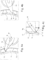
- the Figure 1 shows a schematic overview representation of a method for manufacturing a solid cage 1 as a solid component, as this in the Figure 1 is shown at the bottom right.
- the solid cage 1 is designed for installation in a roller bearing and has a plurality of webs 2 as intermediate regions, which are arranged in a regularly distributed manner in a circumferential direction about a cage rotation axis K.
- a pocket 3 for receiving a rolling element, in this example a roller, is arranged between the webs 2.
- Side rings 4 are arranged on the axial end side, the webs 2 and / or the pockets 3 extending between the side rings 4.
- the solid cage 1 is formed in one piece.
- Each of the webs 2 has a first web side 5a as the first pocket side and a second web side 5b as a second pocket side.
- the first web sides are oriented in a clockwise direction and the second web sides in an anti-clockwise direction.
- the reference numerals are only shown by way of example on two webs 2.
- all first web sides 5a are oriented in the same direction and all second web sides 5b in the same opposite direction.
- the first and second web sides 5a, b serve as contact surfaces for the rolling elements, in particular for the rollers.
- the first and second web sides 5a, b are oriented in particular in one direction of rotation.
- this has snap lugs 6 which are integrally formed radially on the inside on the webs 2 and which, when the rolling bearing is assembled, serve to enable rollers to be snapped into the pockets 3 and there to be captive being held.
- the method for producing the solid cage is carried out using a so-called cycloid machining, a tool cutting edge being guided in cycloid paths relative to the workpiece to the solid cage 1 in this case.
- a so-called cycloid machining a tool cutting edge being guided in cycloid paths relative to the workpiece to the solid cage 1 in this case.
- a manufacturing device 7 is shown in a highly schematic axial plan view.
- the manufacturing device 7 is designed to rotate the solid cage 1 about the cage rotation axis K in a first cage rotation direction KD1.
- the production device 7 has a rotary drive 8, for example a spindle drive, the rotary drive 8 defining a tool axis of rotation W.
- the cage rotation axis K and the tool rotation axis W are arranged parallel to one another, but offset by an infeed distance Z from one another.
- the rotary drive 8 rotates a tool cutting edge 9 of a chisel 10 in a tool rotation direction WD1, the tool cutting edge 9 being spaced apart from the tool rotation axis W by a radial vector R and being set at a pitch angle ⁇ with respect to the radial vector R. Due to a simultaneous rotation of the solid cage 1 about the cage rotation axis K and the tool cutting edge 9 about the tool rotation axis W, the tool cutting edge 9 describes a cycloid path relative to the solid cage 1, like this with the reference symbol Z in the Figure 3 is shown.
- the cycloidal path Z is formed by a corresponding rotation of the solid cage 1 and tool cutting edge 9 such that loops 11 of the cycloidal path Z are arranged in the pockets 3.
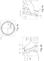
- FIG. 2a An embodiment of the production device 7 is shown, in which the tool axis of rotation W is arranged outside the solid component, in this exemplary embodiment of the solid cage 1, and thus the cutting edge 9 is fed radially from the outside to the solid component.
- FIG 2b an embodiment of the production device 7 is shown, in which the tool axis of rotation W is arranged within the solid component, so that the tool cutting edge 9 is fed from the inside radially to the solid component.
- the pockets 3 are not introduced in a single production step by means of the cycloid processing, rather the introduction takes place via three individual steps, as is subsequently described in connection with the Figure 1 is further explained.
- a cage blank 12 which already has raw webs 13 at the positions of the later webs 2 and raw pockets 14.
- the raw pockets 13 can in principle be introduced as desired, but it is particularly simple in terms of production technology if they are introduced as a rough processing step via a pre-cycloid processing step.
- the pre-cycloid processing step is based on the Figures 4a, b, c explained.
- the Figures 4a, b, c each show a detail of the cage blank 12, wherein the raw webs 13 and the raw pockets 14 can already be seen.
- the tool cutting edge 9 is run along a pre-cycloid path ( Figure 4c ) 15 led.
- the sides of the raw webs 13, which correspond to the later first web sides 5a, are produced along this path by means of a cutting process.
- FIG. 4b how this results from the Figure 4b results - the sides of the raw webs 13, which later correspond to the second web sides 5b, finished in a shabby fashion.
- the Figure 4c is the rake angle in the pre-cycloid machining step on the second land side 5b Figure 4b drawn with -5 degrees.
- the pre-cycloid processing step thus introduces openings in the form of the raw pockets 14 into the cage blank 12.
- the surface quality, in particular the web side, which later corresponds to the second web side 5b and which has been machined and / or machined with a negative rake angle, is not sufficiently precise for the requirement of the solid cage 1.
- the first and the second are finished Web side 5a, b via a first and a second cycloid processing step.
- the result of the first cycloid machining step is in the Figure 1 shown at the bottom left, the first web sides 5a being finished in the first cycloid processing step.
- the tool cutting edge 9 of the chisel 10 or a further tool cutting edge 9 of another chisel 10 is guided along a first cycloid path.
- the first cycloid path is arranged offset in the circumferential direction about the cage axis of rotation K to the pre-cycloid path of the pre-cycloid processing step.
- the Figures 5a, b, c show the first cycloid machining step. From the Figure 5a it can be seen that for the first cycloid machining step the solid cage 1 or in the state of the cage blank 12 is rotated by an angle of 3.5 degrees about the cage rotation axis K in this example. This results in a phase shift of the first cycloid orbit compared to the pre-cycloid orbit by an amount of the aforementioned 3.5 degrees. In particular, the minima and / or the maxima of the first cycloid orbit and the pre-cycloid orbit are offset from one another by the phase offset about the cage rotation axis K.
- FIG 5b The immersion of the tool cutting edge 9 is shown, wherein it can be seen that the tool cutting edge 9 is guided along the first cycloid path in such a way that the tool cutting edge 9 cuts the first web sides 5a.
- the Figure 5c shows the exit of the tool cutting edge 9 from the pocket 3, wherein it can be seen that it is guided at a distance and / or without contact to the side of the raw webs 13, which later form the second web side 5b.
- the cage rotation direction KD1 of the solid cage or cage blank 12 and the tool rotation direction WD1 of the tool cutting edge 9 about the tool rotation axis W are opposite to one another.
- a second cycloid processing step takes place.
- this second cycloid machining step like this one in the Figures 6a, b, c is shown, the angle of attack alpha of the cutting edge 9 is changed.
- the chisel 10 is turned 180 degrees.
- the second cycloid path is also phase-shifted from the pre-cycloid path, but in this case by 3.5 ° in the opposite direction.
- the directions of rotation of the solid cage 1 or of the cage blank 12 and of the tool cutting edge 9 are reversed about the tool axis of rotation W, so that the solid cage 1 or the cage blank 12 are rotated about a counter cage direction of rotation KD2 and the tool cutting edge in a tool counter direction of rotation WD2.
- the tool cutting edge 9 is guided in such a way that in the second cycloid machining step the second web sides 5b are cut and the rake angle of the tool cutting edge 9 is negative.
- the tool cutting edge 9 is again contact-free to the first web sides 5a.
- the shape of the first and second cycloid orbits is the same, but in opposite directions, and is offset by a total of twice the phase offset, that is to say offset by 7 ° to one another in this example.
- Both the first web sides 5a and the second web sides 5b are thus cut or machined with a negative rake angle of the tool cutting edge 9, so that they have a high surface quality or can be represented as a finishing operation.
- the snap lugs 6 are also produced by the first and the second cycloid processing step.
- a solid component designed as a solid shaft 16 is shown in a sectional view or in a radial top view.
- the solid shaft 16 has a plurality of pockets 3, which in this exemplary embodiment are configured as sack pockets and not as through pockets as in the previous figures.
- the pockets 3 can be introduced via the process sequence of the pre-cycloid processing step and the cycloid processing steps.
Landscapes
- Engineering & Computer Science (AREA)
- Mechanical Engineering (AREA)
- General Engineering & Computer Science (AREA)
- Physics & Mathematics (AREA)
- Geometry (AREA)
- Rolling Contact Bearings (AREA)
Claims (15)
- Procédé de fabrication d'un composant solide, notamment une cage solide (1) pour palier de roulement,
le composant solide définissant un axe de rotation de composant (K1) ét comportant une pluralité de poches (3), les poches (3) ayant chacune un premier et un second côté de poche (5a, b), comprenant les étapes suivantes consistant à :former une ébauche de composant (12) lors d'une étape d'ébauchage au moyen d'un outil d'ébauchage, l'ébauche de composant (12) formant une pluralité de poches brutes (14) ;former les premiers côtés de la poche (5a) dans le contour final au moyen d'un tranchant d'outil (9), le tranchant d'outil (9) étant guidé lors d'une première étape de traitement cycloïde par rapport à l'ébauche de composant (12) tournant autour de l'axe de rotation de composant (K1) dans une direction de rotation de composant (KD1) le long d'une première trajectoire cycloïde pour traiter les poches brutes (14), les premiers côtés de la poche (5a) étant découpés au moyen du tranchant d'outil (9) et un angle de coupe du tranchant d'outil (9) se situant dans la plage allant de -15° à 0° ;inverser la direction de rotation du composant (KD1) de l'ébauche de composant (12) et faire tourner l'ébauche de composant (12) dans une direction contraire du composant (KD2) ;former les seconds côtés de poche (5b) dans le contour final au moyen d'un autre tranchant d'outil (9), l'autre tranchant d'outil (9) étant guidé lors d'une seconde étape de traitement cycloïde par rapport à l'ébauche de composant (12) tournant autour de l'axe de rotation de composant (K1) dans la direction contraire du composant (KD2), le long d'une seconde trajectoire cycloïde pour traiter les poches brutes (14), les seconds côtés de poche (5b) étant découpés au moyen de l'autre tranchant d'outil (9) et un angle de coupe de l'autre tranchant d'outil (9) se situant dans la plage allant de -15° à 0°. - Procédé selon la revendication 1, caractérisé en ce que le tranchant d'outil (9) et l'ébauche de composant (12) tournent dans le sens opposé, à condition que le tranchant d'outil (9) commence à couper sur une circonférence extérieure de l'ébauche de composant (12) ou en ce que le tranchant d'outil (9) et l'ébauche de composant (12) tournent dans le même sens, à condition que l'ébauche de composant (12) soit en forme d'anneau et que le tranchant d'outil (9) commence à couper sur une circonférence intérieure de l'ébauche de composant (12).
- Procédé selon la revendication 1 ou la revendication 2, caractérisé en ce que lors de l'étape d'ébauchage, l'ébauche de composant (12) tourne autour de l'axe de rotation de composant (K1) et l'outil d'ébauchage autour d'un axe de rotation d'outil (W), un couplage des mouvements de rotation de l'axe de rotation de composant (K1) et de l'axe de rotation d'outil (W) étant effectué, en ce que l'ébauche de composant (12) tourne autour de l'axe de rotation de composant (K1) et les tranchants d'outil (9) autour de l'axe de rotation d'outil (W) lors des étapes de traitement cycloïde et en ce que l'axe de rotation de composant (K1) et l'axe de rotation d'outil (W) sont découplés avant la réalisation des étapes de traitement cycloïde respectives, l'ébauche de composant (12) étant de nouveau entraînée en rotation d'un angle alpha autour de l'axe de rotation de composant (K1) et l'axe de rotation de composant (K1) étant à nouveau couplé avec l'axe de rotation d'outil (W).
- Procédé selon la revendication 3, caractérisé en ce que la distance d'avance (Z) entre l'axe de rotation de composant (K1) et l'axe de rotation de l'outil (W) est modifiée.
- Procédé selon la revendication 4, caractérisé en ce que la distance d'avance (Z) est modifiée en fonction d'une position axiale du tranchant d'outil (9) par rapport à l'ébauche de composant (12) afin de conférer aux poches (3) une forme trapézoïdale vues dans une direction perpendiculaire à l'axe de rotation de composant (K1) et sur une circonférence extérieure du composant solide.
- Procédé selon l'une quelconque des revendications 1 à 5 précédentes, caractérisé en ce que chaque poche (3) présente deux faces avant, au moins une des faces avant ayant une forme sensiblement trapézoïdale dans la direction de l'axe de rotation de composant (K1).
- Procédé selon l'une quelconque des revendications précédentes, caractérisé en ce que les poches brutes (14) sont introduites dans l'ébauche de composant (12) par une étape de traitement cycloïde préalable, l'outil d'ébauchage étant guidé par rapport à l'ébauche de composant (12) tournant autour de l'axe de rotation de composant (K1), dans une direction de rotation de composant (KD1) le long d'au moins une autre trajectoire cycloïde pour former les poches brutes (14).
- Procédé selon l'une quelconque des revendications précédentes, caractérisé en ce que le composant solide est conçu comme une cage solide (1) pour un palier de roulement, la cage solide (1) définissant un axe de rotation de cage (K) et présentant une pluralité de traverses (2), qui forment les poches (3) pour recevoir des éléments de roulement, les poches (3) ayant chacune des premier et second côtés de poche (5a, b) pour porter les éléments de roulement dans la direction circonférentielle autour de l'axe de rotation de cage (K).
- Composant solide, en particulier cage solide (1) pour un palier de roulement ou un arbre plein, le composant solide définissant un axe de rotation de composant (K1) et ayant une pluralité de poches (3), les poches (3) ayant chacune un premier et un second côté de poche (5a, b) et deux faces avant,
caractérisé en ce que
le composant solide est fabriqué par le procédé selon l'une quelconque des revendications précédentes. - Composant solide selon la revendication 9, caractérisé en ce qu'une surface des poches (3) dans la région des premier et second côtés de poche (5a, 5b) a une profondeur de rugosité moyenne Rz d'au plus 10 µm.
- Composant solide selon la revendication 9 ou la revendication 10, caractérisé en ce qu'une circonférence de chaque poche (3) vue dans une direction perpendiculaire à l'axe de rotation du composant (K1) et à une circonférence extérieure du composant solide et/ou au moins une face avant de chaque poche (3) est/sont approximativement trapézoïdales.
- Composant solide selon l'une quelconque des revendications 9 à 11, caractérisé en ce que la circonférence de chaque poche (3), vue dans une direction perpendiculaire à l'axe de rotation de composant (K1) et à une circonférence extérieure du composant solide et/ou une circonférence d'au moins une des faces d'extrémité est asymétrique.
- Composant solide selon l'une quelconque des revendications 9 à 12, caractérisé en ce que le composant solide forme une cage solide (1) pour un palier de roulement et est conçue sous forme annulaire, la cage solide (1) définissant un axe de rotation de cage (K) et présentant une pluralité de traverses (2), qui forment les poches (3) pour recevoir des éléments de roulement, les poches (3) ayant chacune des premier et second côtés de poche (5a, b) pour porter les éléments de roulement dans la direction circonférentielle autour de l'axe de rotation de cage (K).
- Composant solide selon l'une quelconque des revendications 9 à 12, caractérisé en ce que le composant solide forme une cage solide (1) pour un palier de roulement et la cage solide (1) est conçue sous forme de demi-coquille, la cage solide (1) définissant un axe de rotation de cage (K) et présentant une pluralité de traverses (2), qui forment les poches (3) pour recevoir des éléments de roulement, les poches (3) ayant chacune des premier et second côtés de poche (5a, b) pour porter les éléments de roulement dans la direction circonférentielle autour de l'axe de rotation de cage (K).
- Composant solide selon l'une quelconque des revendications 13 ou 14, caractérisé en ce qu'une circonférence extérieure de la cage solide (1) a un diamètre supérieur à 250 mm.
Priority Applications (1)
| Application Number | Priority Date | Filing Date | Title |
|---|---|---|---|
| PL16816184T PL3380739T3 (pl) | 2015-11-24 | 2016-11-18 | Sposób wytwarzania masywnej części konstrukcyjnej, jak również masywna część konstrukcyjna |
Applications Claiming Priority (2)
| Application Number | Priority Date | Filing Date | Title |
|---|---|---|---|
| DE102015223180.1A DE102015223180A1 (de) | 2015-11-24 | 2015-11-24 | Verfahren zum Fertigen eines Massivbauteils sowie ein Massivbauteil |
| PCT/DE2016/200524 WO2017088871A1 (fr) | 2015-11-24 | 2016-11-18 | Procédé de fabrication d'un composant solide et composant solide |
Publications (2)
| Publication Number | Publication Date |
|---|---|
| EP3380739A1 EP3380739A1 (fr) | 2018-10-03 |
| EP3380739B1 true EP3380739B1 (fr) | 2020-03-25 |
Family
ID=57590285
Family Applications (1)
| Application Number | Title | Priority Date | Filing Date |
|---|---|---|---|
| EP16816184.2A Active EP3380739B1 (fr) | 2015-11-24 | 2016-11-18 | Procédé de fabrication d'un composant solide et composant solide |
Country Status (7)
| Country | Link |
|---|---|
| EP (1) | EP3380739B1 (fr) |
| CN (1) | CN108291579B (fr) |
| DE (1) | DE102015223180A1 (fr) |
| ES (1) | ES2790856T3 (fr) |
| HU (1) | HUE050176T2 (fr) |
| PL (1) | PL3380739T3 (fr) |
| WO (1) | WO2017088871A1 (fr) |
Families Citing this family (2)
| Publication number | Priority date | Publication date | Assignee | Title |
|---|---|---|---|---|
| DE102018101551A1 (de) | 2018-01-24 | 2018-12-13 | Schaeffler Technologies AG & Co. KG | Käfig für ein Wälzlager, Verfahren zum Fertigen des Käfigs sowie ein Käfigrohling |
| CN110961705B (zh) * | 2019-12-25 | 2021-05-25 | 中国航发哈尔滨轴承有限公司 | 短圆柱滚子轴承保持架方兜孔的铣削方法 |
Family Cites Families (8)
| Publication number | Priority date | Publication date | Assignee | Title |
|---|---|---|---|---|
| JPS5226345B2 (fr) * | 1972-10-05 | 1977-07-13 | ||
| DE8912970U1 (fr) | 1989-11-02 | 1991-02-28 | Ley, Hans, 5203 Much, De | |
| DE4212238A1 (de) * | 1992-04-11 | 1993-10-14 | Heckler & Koch Gmbh | Verfahren zum Herstellen von Werkstücken, die auf einer Umfangsfläche mit Ausnehmungen versehen sind, und Vorrichtung zur Durchführung des Verfahrens |
| CN1222876A (zh) * | 1996-06-21 | 1999-07-14 | 伊普罗泰克机械及特殊钢产品有限公司 | 加工非圆形内轮廓和/或外轮廓的方法和装置 |
| CN2924146Y (zh) * | 2006-06-01 | 2007-07-18 | 时传坤 | 一种二类轴承组合保持架 |
| DE102006047544A1 (de) * | 2006-10-07 | 2008-04-10 | Schaeffler Kg | Metallkäfig für Rollenlager |
| CN201487086U (zh) * | 2009-06-23 | 2010-05-26 | 台州市迈肯隆机械有限公司 | 单向组合轴承保持器 |
| JP2014190394A (ja) * | 2013-03-27 | 2014-10-06 | Nsk Ltd | 円すい転がり軸受用保持器 |
-
2015
- 2015-11-24 DE DE102015223180.1A patent/DE102015223180A1/de not_active Withdrawn
-
2016
- 2016-11-18 HU HUE16816184A patent/HUE050176T2/hu unknown
- 2016-11-18 EP EP16816184.2A patent/EP3380739B1/fr active Active
- 2016-11-18 PL PL16816184T patent/PL3380739T3/pl unknown
- 2016-11-18 CN CN201680068778.3A patent/CN108291579B/zh active Active
- 2016-11-18 ES ES16816184T patent/ES2790856T3/es active Active
- 2016-11-18 WO PCT/DE2016/200524 patent/WO2017088871A1/fr unknown
Also Published As
| Publication number | Publication date |
|---|---|
| CN108291579A (zh) | 2018-07-17 |
| WO2017088871A1 (fr) | 2017-06-01 |
| HUE050176T2 (hu) | 2020-11-30 |
| DE102015223180A1 (de) | 2017-05-24 |
| EP3380739A1 (fr) | 2018-10-03 |
| CN108291579B (zh) | 2020-08-21 |
| PL3380739T3 (pl) | 2020-07-27 |
| ES2790856T3 (es) | 2020-10-29 |
Similar Documents
| Publication | Publication Date | Title |
|---|---|---|
| EP3191248B1 (fr) | Dispositif de taillage en développante d'une pièce pour la production d'un chanfrein et procédé de fonctionnement associé | |
| EP3274118B1 (fr) | Procédé et dispositif servant à tailler des roues d'usinage par décolletage en développante | |
| DE102010061432B4 (de) | Verfahren und Werkzeug zur Herstellung eines Zahnrades mit balligen Zähnen | |
| DE102014019740B4 (de) | Vorrichtung zur Wälzschälbearbeitung eines Werkstücks zur Fertigung einer Fase mit rotierbarer Werkzeugspindel-Halterung und zugehöriges Betriebsverfahren | |
| WO2009007280A1 (fr) | Procédé de fraisage de pistes à billes et fraiseuse à disque pour pistes à billes | |
| EP3380739B1 (fr) | Procédé de fabrication d'un composant solide et composant solide | |
| EP1967307B1 (fr) | Procédé de fabrication d'un élément de moyeu de rotor pourvu de rainures | |
| DE4034516C2 (de) | Verfahren zur Herstellung von Werkstücken mit im wesentlichen kreisringförmiger Grundform, die auf einer Umfangsfläche mit Ausnehmungen versehen sind | |
| EP3620251B1 (fr) | Procédé d'usinage de denture d'une pièce à usiner, machine à tailler les engrenages et logiciel correspondant | |
| EP3380262B1 (fr) | Dispositif de fabrication pour la fabrication d'une pièce pleine et procédé de fabrication de la piece pleine à l'aide du dispositif de fabrication | |
| WO2017063730A1 (fr) | Procédé d'usinage d'une denture ainsi qu'ensemble, outil d'usinage et machine-outil associés | |
| EP3528987B1 (fr) | Procédé et dispositif d'usinage de couronnes d'orientation à billes et nervures de guidage d'une partie intérieure de joint homocinétique | |
| EP3898079B1 (fr) | Procédé de traitement de surface, composant de roulement et dispositif | |
| EP2794159A2 (fr) | Procédé et dispositif d'usinage d'arêtes longitudinales de pièces métalliques | |
| EP3494317B1 (fr) | Anneau d'extrémité d'une cage de roulement en pièces multiples parts, procédé de fabrication de l'anneau d'extrémité et cage de roulement en pièces multiples | |
| EP3209442A1 (fr) | Foret hélicoïdal et procédé de fabrication | |
| DE102004003147B4 (de) | Verfahren und Vorrichtung zum Fräsen von Kugellaufbahnen an Gleichlaufgelenknaben | |
| DE102009058214A1 (de) | Verfahren zur Bearbeitung einer Werkstückoberfläche und zugehöriges Werkzeug | |
| DE102009041372A1 (de) | Ringförmiger Massivkäfig für zylindrische oder tonnenförmige Wälzkörper | |
| DE102021112363A1 (de) | Bearbeitungs-Werkzeug zur Schneid- und/oder Formbearbeitung der Innenwandung einer Werkstück-Bohrung | |
| DE102014019817B3 (de) | Vorrichtung zum Wälzfräsen sowie zur Wälzschälbearbeitung eines Werkstücks zur Fertigung einer Fase und zugehöriges Betriebsverfahren | |
| EP3852962A1 (fr) | Procédé et dispositif de fabrication d'une denture d'une roue dentée à l'aide d'un outil | |
| DE102019204010A1 (de) | Lagerkäfig |
Legal Events
| Date | Code | Title | Description |
|---|---|---|---|
| STAA | Information on the status of an ep patent application or granted ep patent |
Free format text: STATUS: UNKNOWN |
|
| STAA | Information on the status of an ep patent application or granted ep patent |
Free format text: STATUS: THE INTERNATIONAL PUBLICATION HAS BEEN MADE |
|
| PUAI | Public reference made under article 153(3) epc to a published international application that has entered the european phase |
Free format text: ORIGINAL CODE: 0009012 |
|
| STAA | Information on the status of an ep patent application or granted ep patent |
Free format text: STATUS: REQUEST FOR EXAMINATION WAS MADE |
|
| 17P | Request for examination filed |
Effective date: 20180416 |
|
| AK | Designated contracting states |
Kind code of ref document: A1 Designated state(s): AL AT BE BG CH CY CZ DE DK EE ES FI FR GB GR HR HU IE IS IT LI LT LU LV MC MK MT NL NO PL PT RO RS SE SI SK SM TR |
|
| AX | Request for extension of the european patent |
Extension state: BA ME |
|
| DAV | Request for validation of the european patent (deleted) | ||
| DAX | Request for extension of the european patent (deleted) | ||
| REG | Reference to a national code |
Ref country code: DE Ref legal event code: R079 Ref document number: 502016009325 Country of ref document: DE Free format text: PREVIOUS MAIN CLASS: F16C0033460000 Ipc: B23Q0027000000 |
|
| GRAP | Despatch of communication of intention to grant a patent |
Free format text: ORIGINAL CODE: EPIDOSNIGR1 |
|
| STAA | Information on the status of an ep patent application or granted ep patent |
Free format text: STATUS: GRANT OF PATENT IS INTENDED |
|
| RIC1 | Information provided on ipc code assigned before grant |
Ipc: B23Q 27/00 20060101AFI20191030BHEP Ipc: B23C 3/00 20060101ALI20191030BHEP |
|
| INTG | Intention to grant announced |
Effective date: 20191114 |
|
| GRAS | Grant fee paid |
Free format text: ORIGINAL CODE: EPIDOSNIGR3 |
|
| GRAA | (expected) grant |
Free format text: ORIGINAL CODE: 0009210 |
|
| STAA | Information on the status of an ep patent application or granted ep patent |
Free format text: STATUS: THE PATENT HAS BEEN GRANTED |
|
| AK | Designated contracting states |
Kind code of ref document: B1 Designated state(s): AL AT BE BG CH CY CZ DE DK EE ES FI FR GB GR HR HU IE IS IT LI LT LU LV MC MK MT NL NO PL PT RO RS SE SI SK SM TR |
|
| REG | Reference to a national code |
Ref country code: GB Ref legal event code: FG4D Free format text: NOT ENGLISH |
|
| REG | Reference to a national code |
Ref country code: AT Ref legal event code: REF Ref document number: 1248025 Country of ref document: AT Kind code of ref document: T Effective date: 20200415 Ref country code: IE Ref legal event code: FG4D Free format text: LANGUAGE OF EP DOCUMENT: GERMAN |
|
| REG | Reference to a national code |
Ref country code: DE Ref legal event code: R096 Ref document number: 502016009325 Country of ref document: DE |
|
| REG | Reference to a national code |
Ref country code: RO Ref legal event code: EPE |
|
| REG | Reference to a national code |
Ref country code: SE Ref legal event code: TRGR |
|
| PG25 | Lapsed in a contracting state [announced via postgrant information from national office to epo] |
Ref country code: NO Free format text: LAPSE BECAUSE OF FAILURE TO SUBMIT A TRANSLATION OF THE DESCRIPTION OR TO PAY THE FEE WITHIN THE PRESCRIBED TIME-LIMIT Effective date: 20200625 Ref country code: FI Free format text: LAPSE BECAUSE OF FAILURE TO SUBMIT A TRANSLATION OF THE DESCRIPTION OR TO PAY THE FEE WITHIN THE PRESCRIBED TIME-LIMIT Effective date: 20200325 Ref country code: RS Free format text: LAPSE BECAUSE OF FAILURE TO SUBMIT A TRANSLATION OF THE DESCRIPTION OR TO PAY THE FEE WITHIN THE PRESCRIBED TIME-LIMIT Effective date: 20200325 |
|
| PG25 | Lapsed in a contracting state [announced via postgrant information from national office to epo] |
Ref country code: GR Free format text: LAPSE BECAUSE OF FAILURE TO SUBMIT A TRANSLATION OF THE DESCRIPTION OR TO PAY THE FEE WITHIN THE PRESCRIBED TIME-LIMIT Effective date: 20200626 Ref country code: LV Free format text: LAPSE BECAUSE OF FAILURE TO SUBMIT A TRANSLATION OF THE DESCRIPTION OR TO PAY THE FEE WITHIN THE PRESCRIBED TIME-LIMIT Effective date: 20200325 Ref country code: HR Free format text: LAPSE BECAUSE OF FAILURE TO SUBMIT A TRANSLATION OF THE DESCRIPTION OR TO PAY THE FEE WITHIN THE PRESCRIBED TIME-LIMIT Effective date: 20200325 Ref country code: BG Free format text: LAPSE BECAUSE OF FAILURE TO SUBMIT A TRANSLATION OF THE DESCRIPTION OR TO PAY THE FEE WITHIN THE PRESCRIBED TIME-LIMIT Effective date: 20200625 |
|
| REG | Reference to a national code |
Ref country code: NL Ref legal event code: MP Effective date: 20200325 |
|
| REG | Reference to a national code |
Ref country code: LT Ref legal event code: MG4D |
|
| PG25 | Lapsed in a contracting state [announced via postgrant information from national office to epo] |
Ref country code: NL Free format text: LAPSE BECAUSE OF FAILURE TO SUBMIT A TRANSLATION OF THE DESCRIPTION OR TO PAY THE FEE WITHIN THE PRESCRIBED TIME-LIMIT Effective date: 20200325 |
|
| REG | Reference to a national code |
Ref country code: ES Ref legal event code: FG2A Ref document number: 2790856 Country of ref document: ES Kind code of ref document: T3 Effective date: 20201029 |
|
| PG25 | Lapsed in a contracting state [announced via postgrant information from national office to epo] |
Ref country code: PT Free format text: LAPSE BECAUSE OF FAILURE TO SUBMIT A TRANSLATION OF THE DESCRIPTION OR TO PAY THE FEE WITHIN THE PRESCRIBED TIME-LIMIT Effective date: 20200818 Ref country code: CZ Free format text: LAPSE BECAUSE OF FAILURE TO SUBMIT A TRANSLATION OF THE DESCRIPTION OR TO PAY THE FEE WITHIN THE PRESCRIBED TIME-LIMIT Effective date: 20200325 Ref country code: EE Free format text: LAPSE BECAUSE OF FAILURE TO SUBMIT A TRANSLATION OF THE DESCRIPTION OR TO PAY THE FEE WITHIN THE PRESCRIBED TIME-LIMIT Effective date: 20200325 Ref country code: LT Free format text: LAPSE BECAUSE OF FAILURE TO SUBMIT A TRANSLATION OF THE DESCRIPTION OR TO PAY THE FEE WITHIN THE PRESCRIBED TIME-LIMIT Effective date: 20200325 Ref country code: SM Free format text: LAPSE BECAUSE OF FAILURE TO SUBMIT A TRANSLATION OF THE DESCRIPTION OR TO PAY THE FEE WITHIN THE PRESCRIBED TIME-LIMIT Effective date: 20200325 Ref country code: SK Free format text: LAPSE BECAUSE OF FAILURE TO SUBMIT A TRANSLATION OF THE DESCRIPTION OR TO PAY THE FEE WITHIN THE PRESCRIBED TIME-LIMIT Effective date: 20200325 Ref country code: IS Free format text: LAPSE BECAUSE OF FAILURE TO SUBMIT A TRANSLATION OF THE DESCRIPTION OR TO PAY THE FEE WITHIN THE PRESCRIBED TIME-LIMIT Effective date: 20200725 |
|
| REG | Reference to a national code |
Ref country code: HU Ref legal event code: AG4A Ref document number: E050176 Country of ref document: HU |
|
| REG | Reference to a national code |
Ref country code: DE Ref legal event code: R097 Ref document number: 502016009325 Country of ref document: DE |
|
| PG25 | Lapsed in a contracting state [announced via postgrant information from national office to epo] |
Ref country code: IT Free format text: LAPSE BECAUSE OF FAILURE TO SUBMIT A TRANSLATION OF THE DESCRIPTION OR TO PAY THE FEE WITHIN THE PRESCRIBED TIME-LIMIT Effective date: 20200325 Ref country code: DK Free format text: LAPSE BECAUSE OF FAILURE TO SUBMIT A TRANSLATION OF THE DESCRIPTION OR TO PAY THE FEE WITHIN THE PRESCRIBED TIME-LIMIT Effective date: 20200325 |
|
| PLBE | No opposition filed within time limit |
Free format text: ORIGINAL CODE: 0009261 |
|
| STAA | Information on the status of an ep patent application or granted ep patent |
Free format text: STATUS: NO OPPOSITION FILED WITHIN TIME LIMIT |
|
| 26N | No opposition filed |
Effective date: 20210112 |
|
| PG25 | Lapsed in a contracting state [announced via postgrant information from national office to epo] |
Ref country code: SI Free format text: LAPSE BECAUSE OF FAILURE TO SUBMIT A TRANSLATION OF THE DESCRIPTION OR TO PAY THE FEE WITHIN THE PRESCRIBED TIME-LIMIT Effective date: 20200325 |
|
| PG25 | Lapsed in a contracting state [announced via postgrant information from national office to epo] |
Ref country code: MC Free format text: LAPSE BECAUSE OF FAILURE TO SUBMIT A TRANSLATION OF THE DESCRIPTION OR TO PAY THE FEE WITHIN THE PRESCRIBED TIME-LIMIT Effective date: 20200325 |
|
| REG | Reference to a national code |
Ref country code: CH Ref legal event code: PL |
|
| GBPC | Gb: european patent ceased through non-payment of renewal fee |
Effective date: 20201118 |
|
| PG25 | Lapsed in a contracting state [announced via postgrant information from national office to epo] |
Ref country code: LU Free format text: LAPSE BECAUSE OF NON-PAYMENT OF DUE FEES Effective date: 20201118 |
|
| REG | Reference to a national code |
Ref country code: BE Ref legal event code: MM Effective date: 20201130 |
|
| PG25 | Lapsed in a contracting state [announced via postgrant information from national office to epo] |
Ref country code: LI Free format text: LAPSE BECAUSE OF NON-PAYMENT OF DUE FEES Effective date: 20201130 Ref country code: CH Free format text: LAPSE BECAUSE OF NON-PAYMENT OF DUE FEES Effective date: 20201130 |
|
| PG25 | Lapsed in a contracting state [announced via postgrant information from national office to epo] |
Ref country code: IE Free format text: LAPSE BECAUSE OF NON-PAYMENT OF DUE FEES Effective date: 20201118 Ref country code: FR Free format text: LAPSE BECAUSE OF NON-PAYMENT OF DUE FEES Effective date: 20201130 |
|
| PG25 | Lapsed in a contracting state [announced via postgrant information from national office to epo] |
Ref country code: GB Free format text: LAPSE BECAUSE OF NON-PAYMENT OF DUE FEES Effective date: 20201118 |
|
| PG25 | Lapsed in a contracting state [announced via postgrant information from national office to epo] |
Ref country code: MT Free format text: LAPSE BECAUSE OF FAILURE TO SUBMIT A TRANSLATION OF THE DESCRIPTION OR TO PAY THE FEE WITHIN THE PRESCRIBED TIME-LIMIT Effective date: 20200325 Ref country code: CY Free format text: LAPSE BECAUSE OF FAILURE TO SUBMIT A TRANSLATION OF THE DESCRIPTION OR TO PAY THE FEE WITHIN THE PRESCRIBED TIME-LIMIT Effective date: 20200325 |
|
| PG25 | Lapsed in a contracting state [announced via postgrant information from national office to epo] |
Ref country code: MK Free format text: LAPSE BECAUSE OF FAILURE TO SUBMIT A TRANSLATION OF THE DESCRIPTION OR TO PAY THE FEE WITHIN THE PRESCRIBED TIME-LIMIT Effective date: 20200325 Ref country code: AL Free format text: LAPSE BECAUSE OF FAILURE TO SUBMIT A TRANSLATION OF THE DESCRIPTION OR TO PAY THE FEE WITHIN THE PRESCRIBED TIME-LIMIT Effective date: 20200325 |
|
| PG25 | Lapsed in a contracting state [announced via postgrant information from national office to epo] |
Ref country code: BE Free format text: LAPSE BECAUSE OF NON-PAYMENT OF DUE FEES Effective date: 20201130 |
|
| P01 | Opt-out of the competence of the unified patent court (upc) registered |
Effective date: 20230523 |
|
| PGFP | Annual fee paid to national office [announced via postgrant information from national office to epo] |
Ref country code: TR Payment date: 20231117 Year of fee payment: 8 Ref country code: SE Payment date: 20231120 Year of fee payment: 8 Ref country code: RO Payment date: 20231115 Year of fee payment: 8 Ref country code: HU Payment date: 20231122 Year of fee payment: 8 Ref country code: AT Payment date: 20231121 Year of fee payment: 8 |
|
| PGFP | Annual fee paid to national office [announced via postgrant information from national office to epo] |
Ref country code: PL Payment date: 20231109 Year of fee payment: 8 |
|
| PGFP | Annual fee paid to national office [announced via postgrant information from national office to epo] |
Ref country code: ES Payment date: 20240129 Year of fee payment: 8 |
|
| PGFP | Annual fee paid to national office [announced via postgrant information from national office to epo] |
Ref country code: DE Payment date: 20240119 Year of fee payment: 8 |