EP3380654B1 - Procede de depot electrolytique d'une couche de conversion sous courant alternatif - Google Patents
Procede de depot electrolytique d'une couche de conversion sous courant alternatif Download PDFInfo
- Publication number
- EP3380654B1 EP3380654B1 EP16819127.8A EP16819127A EP3380654B1 EP 3380654 B1 EP3380654 B1 EP 3380654B1 EP 16819127 A EP16819127 A EP 16819127A EP 3380654 B1 EP3380654 B1 EP 3380654B1
- Authority
- EP
- European Patent Office
- Prior art keywords
- chemical conversion
- strip
- carried out
- alternating current
- comprised
- Prior art date
- Legal status (The legal status is an assumption and is not a legal conclusion. Google has not performed a legal analysis and makes no representation as to the accuracy of the status listed.)
- Active
Links
Images

Classifications
-
- C—CHEMISTRY; METALLURGY
- C25—ELECTROLYTIC OR ELECTROPHORETIC PROCESSES; APPARATUS THEREFOR
- C25D—PROCESSES FOR THE ELECTROLYTIC OR ELECTROPHORETIC PRODUCTION OF COATINGS; ELECTROFORMING; APPARATUS THEREFOR
- C25D9/00—Electrolytic coating other than with metals
- C25D9/04—Electrolytic coating other than with metals with inorganic materials
- C25D9/08—Electrolytic coating other than with metals with inorganic materials by cathodic processes
- C25D9/12—Electrolytic coating other than with metals with inorganic materials by cathodic processes on light metals
-
- C—CHEMISTRY; METALLURGY
- C23—COATING METALLIC MATERIAL; COATING MATERIAL WITH METALLIC MATERIAL; CHEMICAL SURFACE TREATMENT; DIFFUSION TREATMENT OF METALLIC MATERIAL; COATING BY VACUUM EVAPORATION, BY SPUTTERING, BY ION IMPLANTATION OR BY CHEMICAL VAPOUR DEPOSITION, IN GENERAL; INHIBITING CORROSION OF METALLIC MATERIAL OR INCRUSTATION IN GENERAL
- C23C—COATING METALLIC MATERIAL; COATING MATERIAL WITH METALLIC MATERIAL; SURFACE TREATMENT OF METALLIC MATERIAL BY DIFFUSION INTO THE SURFACE, BY CHEMICAL CONVERSION OR SUBSTITUTION; COATING BY VACUUM EVAPORATION, BY SPUTTERING, BY ION IMPLANTATION OR BY CHEMICAL VAPOUR DEPOSITION, IN GENERAL
- C23C22/00—Chemical surface treatment of metallic material by reaction of the surface with a reactive liquid, leaving reaction products of surface material in the coating, e.g. conversion coatings, passivation of metals
- C23C22/05—Chemical surface treatment of metallic material by reaction of the surface with a reactive liquid, leaving reaction products of surface material in the coating, e.g. conversion coatings, passivation of metals using aqueous solutions
- C23C22/06—Chemical surface treatment of metallic material by reaction of the surface with a reactive liquid, leaving reaction products of surface material in the coating, e.g. conversion coatings, passivation of metals using aqueous solutions using aqueous acidic solutions with pH less than 6
- C23C22/34—Chemical surface treatment of metallic material by reaction of the surface with a reactive liquid, leaving reaction products of surface material in the coating, e.g. conversion coatings, passivation of metals using aqueous solutions using aqueous acidic solutions with pH less than 6 containing fluorides or complex fluorides
- C23C22/36—Chemical surface treatment of metallic material by reaction of the surface with a reactive liquid, leaving reaction products of surface material in the coating, e.g. conversion coatings, passivation of metals using aqueous solutions using aqueous acidic solutions with pH less than 6 containing fluorides or complex fluorides containing also phosphates
- C23C22/361—Chemical surface treatment of metallic material by reaction of the surface with a reactive liquid, leaving reaction products of surface material in the coating, e.g. conversion coatings, passivation of metals using aqueous solutions using aqueous acidic solutions with pH less than 6 containing fluorides or complex fluorides containing also phosphates containing titanium, zirconium or hafnium compounds
-
- C—CHEMISTRY; METALLURGY
- C25—ELECTROLYTIC OR ELECTROPHORETIC PROCESSES; APPARATUS THEREFOR
- C25D—PROCESSES FOR THE ELECTROLYTIC OR ELECTROPHORETIC PRODUCTION OF COATINGS; ELECTROFORMING; APPARATUS THEREFOR
- C25D11/00—Electrolytic coating by surface reaction, i.e. forming conversion layers
-
- C—CHEMISTRY; METALLURGY
- C25—ELECTROLYTIC OR ELECTROPHORETIC PROCESSES; APPARATUS THEREFOR
- C25D—PROCESSES FOR THE ELECTROLYTIC OR ELECTROPHORETIC PRODUCTION OF COATINGS; ELECTROFORMING; APPARATUS THEREFOR
- C25D11/00—Electrolytic coating by surface reaction, i.e. forming conversion layers
- C25D11/005—Apparatus specially adapted for electrolytic conversion coating
-
- C—CHEMISTRY; METALLURGY
- C25—ELECTROLYTIC OR ELECTROPHORETIC PROCESSES; APPARATUS THEREFOR
- C25D—PROCESSES FOR THE ELECTROLYTIC OR ELECTROPHORETIC PRODUCTION OF COATINGS; ELECTROFORMING; APPARATUS THEREFOR
- C25D11/00—Electrolytic coating by surface reaction, i.e. forming conversion layers
- C25D11/02—Anodisation
- C25D11/024—Anodisation under pulsed or modulated current or potential
-
- C—CHEMISTRY; METALLURGY
- C25—ELECTROLYTIC OR ELECTROPHORETIC PROCESSES; APPARATUS THEREFOR
- C25D—PROCESSES FOR THE ELECTROLYTIC OR ELECTROPHORETIC PRODUCTION OF COATINGS; ELECTROFORMING; APPARATUS THEREFOR
- C25D11/00—Electrolytic coating by surface reaction, i.e. forming conversion layers
- C25D11/02—Anodisation
- C25D11/04—Anodisation of aluminium or alloys based thereon
- C25D11/06—Anodisation of aluminium or alloys based thereon characterised by the electrolytes used
-
- C—CHEMISTRY; METALLURGY
- C25—ELECTROLYTIC OR ELECTROPHORETIC PROCESSES; APPARATUS THEREFOR
- C25D—PROCESSES FOR THE ELECTROLYTIC OR ELECTROPHORETIC PRODUCTION OF COATINGS; ELECTROFORMING; APPARATUS THEREFOR
- C25D11/00—Electrolytic coating by surface reaction, i.e. forming conversion layers
- C25D11/02—Anodisation
- C25D11/04—Anodisation of aluminium or alloys based thereon
- C25D11/18—After-treatment, e.g. pore-sealing
-
- C—CHEMISTRY; METALLURGY
- C25—ELECTROLYTIC OR ELECTROPHORETIC PROCESSES; APPARATUS THEREFOR
- C25D—PROCESSES FOR THE ELECTROLYTIC OR ELECTROPHORETIC PRODUCTION OF COATINGS; ELECTROFORMING; APPARATUS THEREFOR
- C25D17/00—Constructional parts, or assemblies thereof, of cells for electrolytic coating
- C25D17/005—Contacting devices
-
- C—CHEMISTRY; METALLURGY
- C25—ELECTROLYTIC OR ELECTROPHORETIC PROCESSES; APPARATUS THEREFOR
- C25D—PROCESSES FOR THE ELECTROLYTIC OR ELECTROPHORETIC PRODUCTION OF COATINGS; ELECTROFORMING; APPARATUS THEREFOR
- C25D9/00—Electrolytic coating other than with metals
- C25D9/04—Electrolytic coating other than with metals with inorganic materials
- C25D9/06—Electrolytic coating other than with metals with inorganic materials by anodic processes
-
- C—CHEMISTRY; METALLURGY
- C25—ELECTROLYTIC OR ELECTROPHORETIC PROCESSES; APPARATUS THEREFOR
- C25D—PROCESSES FOR THE ELECTROLYTIC OR ELECTROPHORETIC PRODUCTION OF COATINGS; ELECTROFORMING; APPARATUS THEREFOR
- C25D17/00—Constructional parts, or assemblies thereof, of cells for electrolytic coating
- C25D17/02—Tanks; Installations therefor
Definitions
- the present invention relates to a process for the continuous treatment of an aluminum alloy surface.
- the surface of a metal is provided with a surface treatment for the purpose of enhancing characteristics such as corrosion resistance and the like.
- a surface treatment for the purpose of enhancing characteristics such as corrosion resistance and the like.
- the formation of conversion layers is known in which the initial passive film is replaced by a passivation film comprising other protective metallic elements.
- the chemical conversion carried out in particular with treatment agents containing chromates, in particular at oxidation degree VI has been applied for a long time.
- the environmental problems linked to the use of chromium at oxidation degree VI (chromium (VI)) in treatment solutions have led to a search for treatment agents which do not contain this element at this oxidation degree.
- Treatment agents have thus been developed containing anions containing at least one element from the group consisting of zirconium, titanium, chromium in oxidation degree III, cerium, vanadium, molybdenum, manganese.
- the deposition rate carried out with these new treatment agents is often low, which poses in particular the problem of productivity of the treatment lines.
- the patent US 3,960,676 describes a surface treatment process using direct or alternating current in a medium with a pH greater than 6 for compounds of the silicates, borates, phosphates, chromates, molybdates, vanadates and permanganates type.
- the patent application EP 1,486,585 describes a method of metal surface treatment in which a conversion layer is made with a treating agent containing zirconium and fluorine by direct current cathodic electroplating.
- the patent application JP2003027281 describes the use of a cathodic electric current to increase the thickness of the layer of conversions based on TiO2 particles.
- the patent application EP1980651 describes methods for producing colored oxides on aluminum by anodizing aluminum in an electrolyte comprising water, sulfuric acid and oxalic acid.
- the anodizing step includes at least two sequential current densities in the electrolyte.
- the current used in the process described in the patent application EP1980651 is preferably a constant direct current or a pulsed direct current. Indeed, the use of an alternating current is in general not favorable to the formation of an anodic oxide layer because the layer dissolves during the cathode phase.
- the oxide layer obtained in anodization is essentially derived from the aluminum itself, not from the electrolyte.
- the thickness of the anode oxide layers obtained is thus of the order of 15 to 100 microns.
- the oxide layer obtained is essentially derived from the electrolyte and the thickness is much smaller, less than 0.1 ⁇ m.
- the pH of the solutions of the patent EP1980651 is certainly less than 2 taking into account the sulfuric acid concentrations indicated.
- a person skilled in the art distinguishes without hesitation an anodic oxide layer and a conversion layer.
- the distinction between chemical conversion and oxide formation by anodization is part of the general technical knowledge of those skilled in the art. So in the reference manual "The surface treatment and finishing of Aluminum and its alloys", S. Wernick and R.Pinner, Robert Drapper LTD, Teddington, 1964, 3rd Editi on, chapter 5 is devoted to chemical conversion layers and chapters 6 to 12 to anodizing.
- the difference in thickness of the films obtained is for example explained on page 194 of this book.
- the patent application EP 0318 403 also relates to the formation of anodic oxide layers.
- the anodization conditions described in this patent application contain in particular a high current density of at least 8 A / dm 2 .
- the patent application US2005 / 115839 relates to an anodizing process for aluminum deposition carried out on parts made of ferrous metals. In the embodiment where alternating current is used, the voltage is about 200V to about 600V.
- the anode layers formed have a thickness of at least 1 ⁇ m, typically between 1 and 20 ⁇ m in a bath of pH between 2.5 and 5.5. The parts are not processed by a continuous processing process.
- the patent application WO 96/19595 describes a highly corrosion resistant, paint-adherent, conversion coating formed on the surface of aluminous metal substrates by contacting these surfaces for 0.5-60 seconds with a water-based surface treatment bath without sludge which has a pH of 1.5 to 4.0 and contains a zirconium compound, a phosphoric acid compound, an oxidizing agent and a compound which is a source of hydrogen fluoride. This contact is preferably followed by rinsing with water and drying. No electric current is applied.
- the aim of the present invention is to achieve a rapid and efficient deposition of a chemical conversion layer on a continuous line by a reaction with a chemical conversion treatment agent comprising at least one anionic compound containing at least one element in the group consisting of zirconium, titanium, chromium (III), cerium, vanadium, molybdenum, manganese.
- the object of the invention is a process for the continuous treatment of an aluminum alloy strip (3) comprising a step of forming a chemical conversion layer on the surface of the strip (3) by a reaction with a chemical conversion treatment agent whose pH is maintained between 2 and 4 comprising at least one anionic compound containing at least one metallic element in the group consisting of zirconium, titanium, chromium in oxidation degree III, cerium, vanadium, molybdenum, manganese, in which the strip (3) is subjected to an alternating current whose density is between 0.1 and 3 A / dm2, the frequency is between 40 and 70Hz and the voltage is between 0.1V and 40V while said chemical conversion treatment reaction is carried out, wherein the thickness of the obtained conversion layer is less than 50nm per face.
- the designation of the alloys is made in accordance with the regulations of The Aluminum Association, known to those skilled in the art.
- a continuous treatment method of a strip (3) of aluminum in which the strip (3) is subjected to an alternating current makes it possible to increase the quantity deposited and / or to reduce the contact time. between the chemical conversion treatment agent and the aluminum alloy strip (3).
- the oxide layer obtained is derived from the aluminum itself, not from the electrolyte
- the oxide layer obtained is essentially derived from the electrolyte.
- the treatment agent comprises at least one anionic compound containing at least one metallic element from the group consisting of zirconium, titanium, chromium (III), cerium, vanadium, molybdenum, manganese.
- the anionic compound is a fluorinated and / or oxidized and / or phosphated compound.
- the anionic compound can in particular be a zirconium fluoride such as ZrF 6 2- , an oxyfluorozirconate such as ZrO x F y (2x-y-4) - or an oxyzirconate such as Z F O 3 2- or ZrO 4 4- .
- the anionic compound comprises fluorine.
- the anionic compound can in particular be a titanium fluoride such as TiF 6 2- , an oxyfluorotitanate such as TiO x F y (2x-y-4) - or an oxytitanate such as TiO 3 2- or T 1 O 4 4- .
- TiF 6 2- an oxyfluorotitanate
- TiO x F y (2x-y-4) - or an oxytitanate such as TiO 3 2- or T 1 O 4 4- .
- the anionic compound contains zirconium and / or titanium and / or fluorine.
- the pH of said chemical conversion treatment agent is maintained between 2 and 4 and preferably between 3 and 4.
- a compound containing fluorine such as, for example, hydrofluoric acid, ammonium fluoride, ammonium hydrogen fluoride, sodium fluoride and sodium hydrogen fluoride, are used in particular in this embodiment.
- fluorine such as, for example, hydrofluoric acid, ammonium fluoride, ammonium hydrogen fluoride, sodium fluoride and sodium hydrogen fluoride.
- compounds can be used alone or in combination of two or more species.
- a method of adjusting the pH by adding nitric acid or ammonium hydroxide to the process bath while measuring the pH using a pH meter is also advantageous.
- the total concentration of anionic compound in the group consisting of zirconium, titanium, chromium (III), cerium, vanadium, molybdenum, manganese in the chemical conversion treatment agent is adjusted between 10 mg / l as a lower limit and 50,000 mg / l as an upper limit based on the equivalent of the metallic element. In this concentration range sufficient protection of the surface can be obtained under satisfactory economic conditions.
- the above-mentioned chemical conversion treatment agent may contain other anti-cancer material. corrosion such as tannic acid, imidazoles, triazines, triazoles, guanines, hydrazines, biguanide, phenolic resin, silane coupling agent, colloidal silica, amines, and phosphoric acid a surfactant; a chelator; and resins.
- corrosion such as tannic acid, imidazoles, triazines, triazoles, guanines, hydrazines, biguanide, phenolic resin, silane coupling agent, colloidal silica, amines, and phosphoric acid a surfactant; a chelator; and resins.
- the alternating current used in the context of the present invention has a current density of between 0.1 and 3 A / dm2 and a current frequency of between 40 and 70 Hz.
- the current density is between 0.2 and 1 A / dm2 and the frequency of the current is between 50 and 60 Hz.
- the voltage is not specifically controlled, it is the voltage resulting from the conditions of current density used and is within 'a range from 0.1 V to 40 V.
- the contact time between the strip (3) and the treatment agent is between 0.1 and 15 seconds, preferably between 1 and 10 seconds and preferably between 2 and 5 seconds.
- the invention has in particular the advantage of allowing a short contact time and / or of increasing the quantity of deposit for a short contact time.
- the temperature of the chemical conversion treatment agent is typically between 10 and 80 ° C, preferably between 20 and 70 ° C.
- a surface preparation step is carried out before the step of forming a chemical conversion layer.
- the surface of the strip (3) made of aluminum alloy is preferably degreased, rinsed with water after having been degreased and optionally cleaned with acid and rinsed with water after cleaning with acid.
- Degreasing is carried out to remove an oily material or a stain adhering to the surface of the substrate and an immersion treatment is usually carried out at a temperature of 30 to 55 ° C using a degreasing agent such as an acidic cleaning liquid or basic.
- rinsing can be carried out with preferably demineralized water.
- the strip (3) is only wrung out.
- a drying step in an oven is carried out after the step of forming a chemical conversion layer and the optional rinsing.
- the chemical conversion treatment reaction is carried out in an electrochemical cell (1) comprising at least two compartments (11, 12) preferably separated by an electrically insulating partition (13) pierced by a slot (131) allowing the passage of the strip (3) and each containing an electrode (21, 22), the said electrodes being subjected to said alternating current produced by a generator (2).
- the strip (3) takes a cathodic polarity in one compartment and anodic in the other.
- the current passes through the strip (3) itself.
- the electrochemical deposits of conversion layers according to the prior art are carried out with cathodic polarization. Surprisingly, the alternation of cathodic and anodic polarization nevertheless makes it possible to obtain an increase in the quantity deposited.
- the present inventors have observed that the use of an alternating current is particularly advantageous because it makes it possible to use the current delivered industrially without the need for a rectifier.
- This embodiment is advantageous because there is no direct contact between the electrodes and the strip (3) which in particular avoids the risk of faults associated with the contacts.
- the electrical contact is made using a contact roller (23).
- the chemical conversion treatment reaction is carried out in an electrochemical cell (1) and containing at least one electrode (21), an alternating current produced by a generator (2) being applied between the contact roller (23) and the counter electrode (21).
- a material of an electrode used as an electrode (21, 22) in the above processing is not particularly limited as long as the electrode does not dissolve in the chemical conversion processing agent and for example, stainless steel, titanium plated with platinum, titanium plated with niobium, carbon, iron, nickel and zinc can be used.
- the material of the electrode (21,22) is graphite.
- the process according to the invention is used to carry out the formation of conversion layers on all types of aluminum alloys, particularly for the alloys of the 1XXX, 3XXX, 4XXX, 5XXX, 6XXX and 7XXX series.
- the thickness of the conversion layer obtained is less than 50 nm per face. Typically, the thickness of the conversion layer obtained is between 8 nm and 30 nm per face.
- the aluminum alloy strips (3) obtained by the process according to the invention are used in particular in the boxing, automotive and decoration industry.
- a chemical conversion layer was carried out by the process according to the invention.
- a strip (3) of AA5052 alloy 220 ⁇ m thick and 270mm wide was continuously treated.
- a surface preparation step was carried out by sprinkling a solution at 50 ° C containing sulfuric acid (6 g / l) and hydrofluoric acid adjusted so as to remove 0.12 g / m 2 / face then rinsing with deionized water.
- the strip (3) is then entered into the electrochemical cell according to the Figure 1 , comprising two compartments separated by an electrically insulating partition pierced by a slot allowing the passage of the strip (3) and each containing an electrode.
- the submerged length was 40 cm per compartment.
- the bath used in the electrochemical cell was a bath containing fluo-titanate anions at a concentration of 100 mg / l expressed as titanium and fluo-zirconate at a concentration of 215 mg / l expressed as zirconium.
- the solution had been neutralized with ammonia to obtain a pH of 3.6.
- the bath temperature was 50 ° C.
- Table 1 Test conditions Trial Contact time Intensity (A) Voltage (V) Current density (A / dm2) 1 - Reference 4s 0 0 0 2 - Invention 4s 3.1 4 0.139 3 - Invention 4s 4 5.1 0.185 4 - Invention 4s 8 10.1 0.370 5 - Invention 4s 16 20.2 0.740 6 - Reference 3s 0 0 0 7 - Invention 3s 4 5.1 0.185 8 - Invention 3s 8 10.1 0.370 9 - Invention 3s 16 20.8 0.740
- the excess bath is removed by a wringing roller at the outlet of the electrochemical cell.
- the layer obtained is dried at 100 ° C.
- the Zr and Ti contents of the layers were measured by X-ray fluorescence (XRF) with calibration by a white control without conversion layer. The results are provided in Table 2.
- Table 2 Quantities of Zr and Ti deposited, measured by X-ray fluorescence.
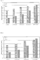
- the figure 3 shows the increase in the average content per face of Ti and Zr when the current density is increased for a contact time of 4 seconds.
- the figure 4 shows the increase in the average content per face Ti and Zr when the current density is increased for a contact time of 3 seconds.
- Tests 4, 5, 8 and 9 are particularly advantageous because the amount deposited is large and the amount of Ti deposited is close to the amount of Zr deposited.
- Test 3 obtained with a current of 8A was characterized by ESCA (Electron Spectroscopy for Chemical Analysis). The analysis of an area of 100 ⁇ m x 500 ⁇ m was carried out using a Quantum 2000 instrument (Physical Electronics), with an X-ray beam of 100 ⁇ m, 15 KV, 25 Watts at an angle of 45 °. Depth profiles after stripping under a voltage of 4KV were also carried out. The results obtained are presented in Table 3 Table 3: Surface compositions of test 3 measured by ESCA (atomic%) and thickness of chemical conversion layer. VS NOT O F Mg Al Yes P Ti Zr Thickness (nm) Upper side 33 0.9 48 2.2 0.5 4.9 0.6 1.3 5.4 3.1 16 Lower side 28 1.5 50 2.0 0.4 4.5 0.6 4.0 7.3 1.7 15
Landscapes
- Chemical & Material Sciences (AREA)
- Engineering & Computer Science (AREA)
- Chemical Kinetics & Catalysis (AREA)
- Materials Engineering (AREA)
- Metallurgy (AREA)
- Organic Chemistry (AREA)
- Electrochemistry (AREA)
- Inorganic Chemistry (AREA)
- General Chemical & Material Sciences (AREA)
- Mechanical Engineering (AREA)
- Chemical Treatment Of Metals (AREA)
- Other Surface Treatments For Metallic Materials (AREA)
Description
- La présente invention se rapporte à un procédé de traitement en continu de surface d'alliage d'aluminium.
- Généralement, la surface d'un le métal est pourvue d'un traitement de surface dans le but de renforcer des caractéristiques telles que la résistance à la corrosion et autres.
On connaît notamment la formation de couches de conversion dans laquelle le film passif initial est remplacé par un film de passivation comprenant d'autres éléments métalliques protecteurs. Ainsi la conversion chimique notamment réalisée avec des agents de traitement contenant des chromates, notamment au degré d'oxydation VI, a été appliquée depuis longtemps. Les problèmes environnementaux liés à l'utilisation du chrome au degré d'oxydation VI (chrome (VI)) dans les solutions de traitement on conduit à rechercher des agents de traitement ne contenant pas cet élément à ce degré d'oxydation. Ont été ainsi mis au point des agents de traitement contenant des anions contenant au moins un élément dans le groupe constitué de zirconium, titane, chrome au degré d'oxydation III, cérium, vanadium, molybdène, manganèse.
Cependant la vitesse de dépôt réalisée avec ces nouveaux agents de traitement est souvent faible ce qui pose notamment le problème de productivité des lignes de traitement. Par ailleurs, il peut être avantageux de pouvoir modifier la quantité de dépôt réalisée sans pour autant modifier la concentration du bain ou le temps de contact. - Le brevet
US 3,960,676 décrit un procédé de traitement de surface avec utilisation de courant continu ou alternatif en milieu à pH supérieur à 6 pour des composés de type silicates, borates, phosphates, chromates, molybdates, vanadates et permanganates.
La demande de brevetEP 1 486 585 décrit une méthode de traitement de surface métallique dans laquelle une couche de conversion est réalisée avec un agent de traitement contenant du zirconium et du fluor par dépôt électrolytique cathodique en courant continu.
La demande de brevetJP2003027281
La demande de brevetEP1980651 décrit des méthodes pour produire des oxydes colorés sur de l'aluminium par anodisation d'aluminium dans un électrolyte comprenant de l'eau, de l'acide sulfurique et de l'acide oxalique. L'étape d'anodisation comprend au moins deux densités de courant séquentielles dans l'électrolyte. Le courant utilisé dans le procédé décrit dans la demande de brevetEP1980651 est préférentiellement un courant continu constant ou un courant continu pulsé. En effet, l'utilisation d'un courant alternatif n'est en général pas favorable à la formation d'une couche d'oxyde anodique car la couche se dissout pendant la phase cathodique. Ainsi qu'il est expliqué dans cette demande la couche d'oxyde obtenue dans une anodisation est essentiellement dérivée de l'aluminium lui-même, pas de l'électrolyte. L'épaisseur des couches d'oxyde anodiques obtenue est ainsi de l'ordre de 15 à 100 microns. Au contraire, dans le cas de la conversion chimique la couche d'oxyde obtenue est essentiellement dérivée de l'électrolyte et l'épaisseur est beaucoup plus faible, inférieure à 0,1 µm. De plus le pH des solutions du brevetEP1980651 est certainement inférieur à 2 compte tenu des concentrations en acide sulfurique indiqués. Ainsi l'homme du métier distingue sans hésiter une couche d'oxyde anodique et une couche de conversion. La distinction entre la conversion chimique et la formation d'oxyde par anodisation fait partie des connaissances techniques générales de l'homme du métier. Ainsi dans le manuel de référence « The surface treatment and finishing of Aluminium and its alloys », S. Wernick et R.Pinner, Robert Drapper LTD, Teddington, 1964, 3rd Edition, le chapitre 5 est consacré aux couches de conversion chimiques et les chapitres 6 à 12 à l'anodisation. La différence d'épaisseur des films obtenus est par exemple expliquée à la page 194 de cet ouvrage. La demande de brevetEP 0318 403 concerne également la formation de couches d'oxyde anodiques. Les conditions d'anodisation décrites dans cette demande de brevet contiennent notamment une densité de courant élevée d'au moins 8 A/dm2.
La demande de brevetUS2005/115839 concerne un procédé d'anodisation de dépôt d'aluminium effectué sur des pièces en métaux ferreux. Dans le mode de réalisation où un courant alternatif est utilisé, la tension est d'environ 200 V à environ 600V. Les couches anodiques formées ont une épaisseur d'au moins 1 µm, typiquement entre 1 et 20 µm dans un bain de pH entre 2,5 et 5,5. Les pièces ne sont pas traitées par un procédé de traitement en continu.
La demande de brevetWO 96/19595 - Le but de la présente invention est de réaliser un dépôt rapide et efficace de couche de conversion chimique sur une ligne en continu par une réaction avec un agent de traitement de conversion chimique comprenant au moins un composé anionique contenant au moins un élément dans le groupe constitué de zirconium, titane, chrome (III), cérium, vanadium, molybdène, manganèse.
- L'objet de l'invention est un procédé de traitement en continu d'une bande (3) en alliage d'aluminium comprenant une étape de formation d'une couche de conversion chimique sur la surface de la bande (3) par une réaction avec un agent de traitement de conversion chimique dont le pH est maintenu entre 2 et 4 comprenant au moins un composé anionique contenant au moins un élément métallique dans le groupe constitué de zirconium, titane, chrome au degré d'oxydation III, cérium, vanadium, molybdène, manganèse, dans lequel la bande (3) est soumise à un courant alternatif dont la densité est comprise entre 0,1 et 3 A/dm2, la fréquence est comprise entre 40 et 70 Hz et la tension est comprise entre 0,1 V et 40V pendant que ladite réaction de traitement de conversion chimique est réalisée, dans lequel l'épaisseur de la couche de conversion obtenue est inférieure à 50 nm par face.
-
-
Figure 1 : Schéma de la cellule électrochimique utilisée dans le cadre d'un premier mode de réalisation de l'invention. -
Figure 2 : Schéma de la cellule électrochimique utilisée dans le cadre d'un second mode de réalisation de l'invention. -
Figure 3 : Evolution du poids de la couche de conversion avec la densité du courant électrique pour un temps de contact de 4s. -
Figure 4 : Evolution du poids de la couche de conversion avec la densité du courant électrique pour un temps de contact de 3s. - La désignation des alliages se fait en conformité avec les règlements de The Aluminium Association, connus de l'homme du métier.
- Selon l'invention, un procédé de traitement en continu d'une bande (3) d'aluminium dans lequel la bande (3) est soumise à un courant alternatif permet d'augmenter la quantité déposée et/ou de diminuer le temps de contact entre l'agent de traitement de conversion chimique et la bande (3) en alliage d'aluminium.
- Contrairement à un traitement d'anodisation, dans lequel la couche d'oxyde obtenue est dérivée de l'aluminium lui-même, pas de l'électrolyte, dans la conversion chimique selon l'invention la couche d'oxyde obtenue est essentiellement dérivée de l'électrolyte.
- L'agent de traitement comprend au moins un composé anionique contenant au moins un élément métallique dans le groupe constitué de zirconium, titane, chrome (III), cérium, vanadium, molybdène, manganèse.
- Avantageusement le composé anionique est un composé fluoré et/ou oxydé et/ou phosphaté.
- Dans le cas du zirconium le composé anionique peut notamment être un fluorure de zirconium tel que ZrF6 2-, un oxyfluorozirconate tel que ZrOxFy (2x-y-4)- ou un oxyzirconate tel que ZFO3 2- ou ZrO4 4-. Avantageusement le composé anionique comprend du fluor.
- Dans le cas du titane le composé anionique peut notamment être un fluorure de titane tel que TiF6 2-, un oxyfluorotitanate tel que TiOxFy (2x-y-4)- ou un oxytitanate tel que TiO3 2- ou T1O4 4-. Ces composés peuvent être utilisés seuls ou en combinaison de deux espèces ou plus.
- Dans un mode de réalisation avantageux le composé anionique contient du zirconium et/ou du titane et/ou du fluor. Le pH dudit agent de traitement de conversion chimique est maintenu entre 2 et 4 et de préférence entre 3 et 4.
- Pour contrôler le pH on utilise notamment dans ce mode de réalisation un composé contenant du fluor tel que par exemple l'acide fluorhydrique, le fluorure d'ammonium, l'hydrogénofluorure d'ammonium, le fluorure de sodium et l'hydrogénofluorure de sodium ces composés peuvent être utilisés seuls ou en combinaison de deux espèces ou plus. Un procédé d'ajustement du pH en rajoutant de l'acide nitrique ou de l'hydroxyde d'ammonium dans le bain de traitement tout en mesurant le pH en utilisant un pH-mètre est également avantageux.
- Au sein du procédé de traitement de surface de la présente invention la concentration totale de composé anionique dans le groupe constitué de zirconium, titane, chrome (III), cérium, vanadium, molybdène, manganèse se trouvant dans l'agent de traitement de conversion chimique est ajustée entre 10 mg/l en tant que limite inférieure et à 50 000 mg/l en tant que limite supérieure sur la base de l'équivalent de l'élément métallique. Dans cette plage de concentration on peut obtenir une protection suffisante de la surface dans des conditions économiques satisfaisantes.
- En plus des ingrédients mentionnés ci-dessus, l'agent de traitement de conversion chimique mentionné ci-dessus peut contenir un autre matériau de prévention de la corrosion tel qu'un acide tannique, des imidazoles, des triazines, des triazoles, des guanines, des hydrazines, de la biguanide, une résine phénolique, un agent de couplage de silane, de la silice colloïdale, des aminés, et de l'acide phosphorique un agent tensio-actif ; un chélateur; et des résines.
- Le courant alternatif utilisé dans le cadre de la présente invention présente une densité de courant comprise entre 0,1 et 3 A/dm2 et une fréquence du courant comprise entre 40 et 70 Hz. De préférence la densité de courant est comprise entre 0,2 et 1 A/dm2 et la fréquence du courant est comprise entre 50 et 60 Hz. La tension n'est pas spécifiquement contrôlée, il s'agit de la tension résultant des conditions de densité de courant utilisée et se trouve à l'intérieur d'une plage allant de 0,1 V à 40 V.
- Avantageusement, le temps de contact entre la bande (3) et l'agent de traitement est compris entre 0,1 et 15 secondes de préférence entre 1 et 10 secondes et de manière préférée entre 2 et 5 secondes. L'invention présente en particulier l'avantage de permettre un faible temps de contact et/ou d'augmenter la quantité de dépôt pour un faible temps de contact.
- La température de l'agent de traitement de conversion chimique est typiquement comprise entre 10 et 80 °C, de préférence entre 20 et 70°C.
- Avantageusement une étape de préparation de surface est effectuée avant l'étape de formation d'une couche de conversion chimique. Ainsi la surface de la bande (3) en alliage d'aluminium est de préférence dégraissée, rincée avec de l'eau après avoir été dégraissée et optionnellement nettoyée à l'acide et rincée avec de l'eau après nettoyage à l'acide. Le dégraissage est réalisé pour enlever une matière huileuse ou une tache adhérant à la surface du substrat et un traitement par immersion est conduit habituellement à une température de 30 à 55 °C en utilisant un agent de dégraissage tel qu'un liquide de nettoyage acide ou basique.
- Après le traitement électrolytique de conversion chimique, on peut effectuer un rinçage avec de l'eau de préférence déminéralisée. Cependant de façon avantageuse, la bande (3) est uniquement essorée.
- Avantageusement une étape de séchage dans un four est effectuée après l'étape de formation d'une couche de conversion chimique et le rinçage optionnel.
- Dans un premier mode de réalisation illustré sur la
Figure 1 , la réaction de traitement de conversion chimique est réalisée dans une cellule électrochimique (1) comprenant au moins deux compartiments (11, 12) de préférence séparés par une cloison électriquement isolante (13) percée par une fente (131) permettant le passage de la bande (3) et contenant chacun une électrode (21, 22), les dites électrodes étant soumises audit courant alternatif produit par un générateur (2). - Lors d'un cycle électrique, la bande (3) prend une polarité cathodique dans un compartiment et anodique dans l'autre. Le courant passe par la bande (3) elle-même. Lors du cycle alternatif suivant, il y a inversion des polarités. Les dépôts électrochimiques de couches de conversion selon l'art antérieur sont réalisés avec une polarisation cathodique. De manière surprenante, l'alternance de polarisation cathodique et anodique permet néanmoins d'obtenir une augmentation de la quantité déposée.
- Les présents inventeurs ont constaté que l'utilisation d'un courant alternatif est particulièrement avantageuse car elle permet d'utiliser le courant délivré industriellement sans nécessité de redresseur. Ce mode de réalisation est avantageux car il n'y a pas de contact direct entre les électrodes et la bande (3) ce qui évite notamment le risque de défauts liés aux contacts.
- Dans un second mode de réalisation illustré par la
Figure 2 , on réalise le contact électrique à l'aide d'un rouleau contacteur (23). Dans ce second mode la réaction de traitement de conversion chimique est réalisée dans une cellule électrochimique (1) et contenant au moins une électrode (21), un courant alternatif produit par un générateur (2) étant appliqué entre le rouleau contacteur (23) et la contre-électrode (21). - Un matériau d'une électrode utilisée en tant qu'électrode (21, 22) au sein du traitement ci-dessus n'est pas particulièrement limité pour autant que l'électrode ne se dissolve pas dans l'agent de traitement de conversion chimique et par exemple, de l'acier inoxydable, du titane plaqué avec du platine, du titane plaqué avec du niobium, du carbone, du fer, du nickel et du zinc peuvent être utilisés. Avantageusement le matériau de l'électrode (21,22) est du graphite.
- Le procédé selon l'invention est utilisé pour réaliser la formation de couches de conversion sur tous types d'alliages d'aluminium, particulièrement pour les alliages des séries 1XXX, 3XXX, 4XXX, 5XXX, 6XXX et 7XXX. L'épaisseur de la couche de conversion obtenue est inférieure à 50 nm par face. Typiquement, l'épaisseur de la couche de conversion obtenue est comprise entre 8 nm et 30 nm par face.
- Les bande (3)s en alliage d'aluminium obtenues par le procédé selon l'invention sont utilisées notamment dans l'industrie du boitage, de l'automobile et de la décoration.
- Dans cet exemple, on a réalisé la formation d'une couche de conversion chimique par le procédé selon l'invention.
Une bande (3) en alliage AA5052 d'épaisseur 220µm et de largeur 270mm a été traitée en continu. Une étape de préparation de surface a été réalisée par aspersion d'une solution à 50 °C contenant de l'acide sulfurique (6 g/l) et de l'acide fluorhydrique ajusté de façon à enlever 0,12 g/m2/face puis un rinçage avec de l'eau déionisée.
La bande (3) est ensuite entrée dans la cellule électrochimique selon laFigure 1 , comprenant deux compartiments séparés par une cloison électriquement isolante percée par une fente permettant le passage de la bande (3) et contenant chacun une électrode. La longueur immergée était de 40 cm par compartiment.
Le bain utilisé dans la cellule électrochimique était un bain contenant des anions fluo-titanate à une concentration de 100 mg/l exprimée en titane et fluo-zirconate à une concentration de 215 mg/l exprimée en zirconium. La solution avait été neutralisée avec de l'ammoniaque pour obtenir un pH de 3,6. La température du bain était de 50 °C. - Un courant électrique alternatif de fréquence 50 Hz a été appliqué aux électrodes sauf dans l'exemple de référence.
Les conditions des essais sont données dans le Tableau 1.Tableau 1 : Conditions des essais Essai Temps de contact Intensité (A) Tension (V) Densité de courant (A/dm2) 1 - Référence 4s 0 0 0 2 - Invention 4s 3,1 4 0,139 3 - Invention 4s 4 5,1 0,185 4 - Invention 4s 8 10,1 0,370 5 - Invention 4s 16 20,2 0,740 6 - Référence 3s 0 0 0 7 - Invention 3s 4 5,1 0,185 8 - Invention 3s 8 10,1 0,370 9 - Invention 3s 16 20,8 0,740 - L'excès de bain est éliminé par un rouleau essoreur en sortie de la cellule électrochimique. La couche obtenue est séchée à 100°C.
Les teneurs en Zr et Ti des couches ont été mesurées par fluorescence rayons X (XRF) avec calibration par un témoin blanc sans couche de conversion. Les résultats sont fournis dans le Tableau 2.Tableau 2 - Quantités de Zr et Ti déposés, mesuré par fluorescence X. Conditions Ti face supérieure (mg/m2) Zr face supérieure (mg/m2) Ti face inférieure (mg/m2) Zr face inférieure (mg/m2) 1 - Référence 4,2 2,0 5,3 1,9 2 - Invention 5,4 3,3 5,9 2,4 3 - Invention 5,8 4,1 6,7 2,8 4 - Invention 5,8 6,1 7,3 3,6 5 - Invention 5,2 8,2 7,8 6,0 6 - Référence 3,3 2,0 3,8 1,3 7 - Invention 4,0 2,9 4,1 1,6 8 - Invention 4,7 4,5 5,0 2,4 9 - Invention 4,3 6,6 5,9 4,3 - La
figure 3 montre l'augmentation de la teneur moyenne par face de Ti et Zr lorsque la densité de courant est augmentée pour un temps de contact de 4 secondes. Lafigure 4 montre l'augmentation de la teneur moyenne par face Ti et Zr lorsque la densité de courant est augmentée pour un temps de contact de 3 secondes. Les essais 4, 5, 8 et 9 sont particulièrement avantageux car la quantité déposée est importante et la quantité de Ti déposé est voisine de la quantité de Zr déposé. - On a caractérisé par ESCA (Electron Spectroscopy for Chemical Analysis) l'essai 3 obtenu avec un courant de 8A. L'analyse d'une aire de 100 µm x 500 µm a été effectuée à l'aide d'un instrument Quantum 2000 (Physical Electronics), avec un faisceau de rayons X de 100 µm, 15 KV, 25 Watts sous un angle de 45 °. Des profils en profondeur après décapage sous une tension de 4KV ont également été effectués.
Les résultats obtenus sont présentés dans le Tableau 3Tableau 3 : Compostions de surface de l'essai 3 mesuré par ESCA (% atomique) et épaisseur de couche de conversion chimique. C N O F Mg Al Si P Ti Zr Epaisseur (nm) Face supérieure 33 0,9 48 2,2 0,5 4,9 0,6 1,3 5,4 3,1 16 Face Inférieure 28 1,5 50 2,0 0,4 4,5 0,6 4,0 7,3 1,7 15
Claims (9)
- Procédé de traitement en continu d'une bande (3) en alliage d'aluminium comprenant une étape de formation d'une couche de conversion chimique sur la surface de ladite bande (3) par une réaction avec un agent de traitement de conversion chimique dont le pH est maintenu entre 2 et 4 comprenant au moins un composé anionique contenant au moins un élément métallique dans le groupe constitué de zirconium, titane, chrome au degré d'oxydation III, cérium, vanadium, molybdène, manganèse, dans lequel ladite bande (3) est soumise à un courant alternatif dont la densité est comprise entre 0,1 et 3 A/dm2, la fréquence est comprise entre 40 et 70 Hz et la tension est comprise entre 0,1 V et 40V pendant que ladite réaction de traitement de conversion chimique est réalisée, dans lequel l'épaisseur de la couche de conversion obtenue est inférieure à 50 nm par face.
- Procédé selon la revendication 1 dans lequel le temps de contact entre ladite bande (3) et ledit agent de traitement est compris entre 0,1 et 15 secondes de préférence entre 1 et 10 secondes et de manière préférée entre 2 et 5 secondes.
- Procédé selon la revendication 1 ou la revendication 2 dans lequel ledit composé anionique contient du zirconium et/ou du titane et/ou du fluor.
- Procédé selon la revendication 3 dans lequel le pH dudit agent de traitement de conversion chimique est maintenu entre 3 et 4.
- Procédé selon une quelconque des revendications 1 à 4 dans lequel l'épaisseur de la couche de conversion obtenue est comprise entre 8 nm et 30 nm par face.
- Procédé selon une quelconque des revendications 1 à 5 dans lequel une étape de préparation de surface est effectuée avant la dite étape de formation d'une couche de conversion chimique.
- Procédé selon une quelconque des revendications 1 à 6 dans lequel une étape de séchage dans un four est effectuée après la dite étape de formation d'une couche de conversion chimique.
- Procédé selon une quelconque des revendications 1 à 7 dans lequel ladite réaction de traitement de conversion chimique est réalisée dans une cellule électrochimique (1) comprenant au moins deux compartiments (11, 12), de préférence séparés par une cloison électriquement isolante (13) percée par une fente (131) permettant le passage de ladite bande (3), et contenant chacun au moins une électrode (21, 22), les dites électrodes étant soumises audit courant alternatif produit par un générateur (2).
- Procédé selon une quelconque des revendications 1 à 7 dans lequel ladite réaction de traitement de conversion chimique est réalisée dans une cellule électrochimique (1) et contenant au moins une électrode (21), un courant alternatif produit par un générateur (2) étant appliqué entre un rouleau contacteur (23) et l'électrode (21).
Applications Claiming Priority (2)
| Application Number | Priority Date | Filing Date | Title |
|---|---|---|---|
| FR1561506A FR3044329A1 (fr) | 2015-11-27 | 2015-11-27 | Procede de depot electrolytique d'une couche de conversion sous courant alternatif |
| PCT/FR2016/053033 WO2017089687A1 (fr) | 2015-11-27 | 2016-11-21 | Procede de depot electrolytique d'une couche de conversion sous courant alternatif |
Publications (2)
| Publication Number | Publication Date |
|---|---|
| EP3380654A1 EP3380654A1 (fr) | 2018-10-03 |
| EP3380654B1 true EP3380654B1 (fr) | 2020-09-02 |
Family
ID=55182410
Family Applications (1)
| Application Number | Title | Priority Date | Filing Date |
|---|---|---|---|
| EP16819127.8A Active EP3380654B1 (fr) | 2015-11-27 | 2016-11-21 | Procede de depot electrolytique d'une couche de conversion sous courant alternatif |
Country Status (3)
| Country | Link |
|---|---|
| EP (1) | EP3380654B1 (fr) |
| FR (1) | FR3044329A1 (fr) |
| WO (1) | WO2017089687A1 (fr) |
Families Citing this family (5)
| Publication number | Priority date | Publication date | Assignee | Title |
|---|---|---|---|---|
| WO2020148412A1 (fr) * | 2019-01-18 | 2020-07-23 | Constellium Neuf-Brisach | Traitement continu de surface de bobines constituées de feuilles d'alliages d'aluminium |
| FR3091880B1 (fr) * | 2019-01-18 | 2022-08-12 | Constellium Neuf Brisach | Traitement de surface en continu des bobines réalisées à partir de tôles d’alliages d’aluminium |
| EP3696299A1 (fr) | 2019-02-15 | 2020-08-19 | Coventya GmbH | Procédé de production d'un moulage en alliage d'aluminium-silicium résistant à la corrosion, moulage en alliage d'aluminium-silicium résistant à la corrosion et son utilisation |
| CN110241453A (zh) * | 2019-04-25 | 2019-09-17 | 西南大学 | 一种缓释氟和铈的可降解锌合金骨钉及其制备方法 |
| WO2021102413A1 (fr) * | 2019-11-22 | 2021-05-27 | Ppg Industries Ohio, Inc. | Procédés de dépôt électrolytique de compositions de prétraitement |
Citations (1)
| Publication number | Priority date | Publication date | Assignee | Title |
|---|---|---|---|---|
| WO1996019595A1 (fr) * | 1994-12-22 | 1996-06-27 | Henkel Corporation | Compositions resistant a la precipitation et procede de traitement de l'aluminium et de ses alliages |
Family Cites Families (7)
| Publication number | Priority date | Publication date | Assignee | Title |
|---|---|---|---|---|
| JPS5121562B2 (fr) * | 1972-04-14 | 1976-07-03 | ||
| DE3312496A1 (de) * | 1983-04-07 | 1984-10-11 | Hoechst Ag, 6230 Frankfurt | Verfahren zur elektrochemischen aufrauhung und anodischen oxidation von aluminium und dessen verwendung als traegermaterial fuer offsetdruckplatten |
| FR2623526B1 (fr) * | 1987-11-23 | 1990-02-23 | Cegedur | Procede d'anodisation en continu de bandes en aluminium ou en un de ses alliages destinees a etre revetues d'un produit organique |
| US7452454B2 (en) * | 2001-10-02 | 2008-11-18 | Henkel Kgaa | Anodized coating over aluminum and aluminum alloy coated substrates |
| US20060032760A1 (en) * | 2004-08-13 | 2006-02-16 | Fuji Photo Film Co., Ltd. | Method of manufacturing lithographic printing plate support |
| US20080274375A1 (en) * | 2007-05-04 | 2008-11-06 | Duracouche International Limited | Anodizing Aluminum and Alloys Thereof |
| US10957468B2 (en) * | 2013-02-26 | 2021-03-23 | General Cable Technologies Corporation | Coated overhead conductors and methods |
-
2015
- 2015-11-27 FR FR1561506A patent/FR3044329A1/fr not_active Ceased
-
2016
- 2016-11-21 EP EP16819127.8A patent/EP3380654B1/fr active Active
- 2016-11-21 WO PCT/FR2016/053033 patent/WO2017089687A1/fr not_active Ceased
Patent Citations (1)
| Publication number | Priority date | Publication date | Assignee | Title |
|---|---|---|---|---|
| WO1996019595A1 (fr) * | 1994-12-22 | 1996-06-27 | Henkel Corporation | Compositions resistant a la precipitation et procede de traitement de l'aluminium et de ses alliages |
Also Published As
| Publication number | Publication date |
|---|---|
| FR3044329A1 (fr) | 2017-06-02 |
| WO2017089687A1 (fr) | 2017-06-01 |
| EP3380654A1 (fr) | 2018-10-03 |
Similar Documents
| Publication | Publication Date | Title |
|---|---|---|
| EP3380654A1 (fr) | Procede de depot electrolytique d'une couche de conversion sous courant alternatif | |
| CA2593489C (fr) | Anodisation d'un alliage d'aluminium | |
| KR102660217B1 (ko) | 박형 양극처리된 필름 층을 함유하는 연속 코일 및 이를 제조하기 위한 시스템 및 방법 | |
| JP2008518097A (ja) | アルミニウムおよびアルミニウム合金被覆基材上の陽極酸化被膜および被覆物品 | |
| WO2000001865A1 (fr) | Procede pour traiter la surface d'une preforme en aluminium | |
| JP5079103B2 (ja) | アルミニウム部材の多機能皮膜 | |
| US20160068986A1 (en) | Anodic oxide film and method for performing sealing treatment thereon | |
| US20240133073A1 (en) | A process to protect light metal substrates | |
| EP2963153B1 (fr) | Procédé de fabrication de tôle d'acier traitée en surface | |
| KR100695999B1 (ko) | 고주파펄스를 이용한 금속재의 아노다이징 공정 | |
| CN102061472A (zh) | 一种镜面铝表面氧化镀膜方法 | |
| KR20190131342A (ko) | 타이타늄모재의 균일한 양극산화피막 형성을 위한 전해액 및 이를 이용한 타이타늄모재의 제조방법 | |
| JP4736084B2 (ja) | マグネシウム又はマグネシウム合金からなる製品の製造方法 | |
| JPS60116800A (ja) | 高速電流反転電解による脱脂及び活性化方法 | |
| KR101365663B1 (ko) | 금속의 양극산화 표면 처리방법 | |
| CN113423873A (zh) | 用于生产耐腐蚀铝硅合金铸件的方法、该耐腐蚀铝硅合金铸件及其用途 | |
| Alshujery et al. | Anodizing of aluminum 6061 alloy with incorporated nanoparticles to inhibits the aluminum corrosion | |
| CN110129855A (zh) | 一种铝合金防腐的表面处理方法 | |
| JPS6144200A (ja) | 亜鉛系片面電気めつき鋼板の製造方法 | |
| JPS607039B2 (ja) | アルミニウムまたはアルミニウム合金の電着塗装法 | |
| JP4783124B2 (ja) | 潤滑皮膜の形成方法。 | |
| JP5095932B2 (ja) | 樹脂被覆アルミニウム板及びその製造方法 | |
| FR3087208A1 (fr) | Procede de traitement de surface de pieces en aluminium | |
| US567612A (en) | Alexander s | |
| Nahin et al. | Variation of Surface Roughness of Chromated and Non-Chromated Al Electroplated Mild Steel |
Legal Events
| Date | Code | Title | Description |
|---|---|---|---|
| STAA | Information on the status of an ep patent application or granted ep patent |
Free format text: STATUS: UNKNOWN |
|
| STAA | Information on the status of an ep patent application or granted ep patent |
Free format text: STATUS: THE INTERNATIONAL PUBLICATION HAS BEEN MADE |
|
| PUAI | Public reference made under article 153(3) epc to a published international application that has entered the european phase |
Free format text: ORIGINAL CODE: 0009012 |
|
| STAA | Information on the status of an ep patent application or granted ep patent |
Free format text: STATUS: REQUEST FOR EXAMINATION WAS MADE |
|
| 17P | Request for examination filed |
Effective date: 20180620 |
|
| AK | Designated contracting states |
Kind code of ref document: A1 Designated state(s): AL AT BE BG CH CY CZ DE DK EE ES FI FR GB GR HR HU IE IS IT LI LT LU LV MC MK MT NL NO PL PT RO RS SE SI SK SM TR |
|
| AX | Request for extension of the european patent |
Extension state: BA ME |
|
| DAV | Request for validation of the european patent (deleted) | ||
| DAX | Request for extension of the european patent (deleted) | ||
| STAA | Information on the status of an ep patent application or granted ep patent |
Free format text: STATUS: EXAMINATION IS IN PROGRESS |
|
| 17Q | First examination report despatched |
Effective date: 20190416 |
|
| REG | Reference to a national code |
Ref country code: DE Ref legal event code: R079 Ref document number: 602016043378 Country of ref document: DE Free format text: PREVIOUS MAIN CLASS: C25D0009120000 Ipc: C23C0022360000 |
|
| RIC1 | Information provided on ipc code assigned before grant |
Ipc: C25D 11/06 20060101ALI20200221BHEP Ipc: C25D 17/02 20060101ALI20200221BHEP Ipc: C25D 11/00 20060101ALI20200221BHEP Ipc: C23C 22/36 20060101AFI20200221BHEP Ipc: C25D 9/06 20060101ALI20200221BHEP Ipc: C25D 9/12 20060101ALI20200221BHEP Ipc: C25D 17/00 20060101ALI20200221BHEP Ipc: C25D 11/02 20060101ALI20200221BHEP Ipc: C25D 11/18 20060101ALI20200221BHEP |
|
| GRAP | Despatch of communication of intention to grant a patent |
Free format text: ORIGINAL CODE: EPIDOSNIGR1 |
|
| STAA | Information on the status of an ep patent application or granted ep patent |
Free format text: STATUS: GRANT OF PATENT IS INTENDED |
|
| INTG | Intention to grant announced |
Effective date: 20200415 |
|
| GRAS | Grant fee paid |
Free format text: ORIGINAL CODE: EPIDOSNIGR3 |
|
| GRAA | (expected) grant |
Free format text: ORIGINAL CODE: 0009210 |
|
| STAA | Information on the status of an ep patent application or granted ep patent |
Free format text: STATUS: THE PATENT HAS BEEN GRANTED |
|
| AK | Designated contracting states |
Kind code of ref document: B1 Designated state(s): AL AT BE BG CH CY CZ DE DK EE ES FI FR GB GR HR HU IE IS IT LI LT LU LV MC MK MT NL NO PL PT RO RS SE SI SK SM TR |
|
| REG | Reference to a national code |
Ref country code: GB Ref legal event code: FG4D Free format text: NOT ENGLISH |
|
| REG | Reference to a national code |
Ref country code: AT Ref legal event code: REF Ref document number: 1308895 Country of ref document: AT Kind code of ref document: T Effective date: 20200915 Ref country code: CH Ref legal event code: EP |
|
| REG | Reference to a national code |
Ref country code: DE Ref legal event code: R096 Ref document number: 602016043378 Country of ref document: DE |
|
| REG | Reference to a national code |
Ref country code: IE Ref legal event code: FG4D Free format text: LANGUAGE OF EP DOCUMENT: FRENCH |
|
| REG | Reference to a national code |
Ref country code: LT Ref legal event code: MG4D |
|
| PG25 | Lapsed in a contracting state [announced via postgrant information from national office to epo] |
Ref country code: NO Free format text: LAPSE BECAUSE OF FAILURE TO SUBMIT A TRANSLATION OF THE DESCRIPTION OR TO PAY THE FEE WITHIN THE PRESCRIBED TIME-LIMIT Effective date: 20201202 Ref country code: BG Free format text: LAPSE BECAUSE OF FAILURE TO SUBMIT A TRANSLATION OF THE DESCRIPTION OR TO PAY THE FEE WITHIN THE PRESCRIBED TIME-LIMIT Effective date: 20201202 Ref country code: LT Free format text: LAPSE BECAUSE OF FAILURE TO SUBMIT A TRANSLATION OF THE DESCRIPTION OR TO PAY THE FEE WITHIN THE PRESCRIBED TIME-LIMIT Effective date: 20200902 Ref country code: HR Free format text: LAPSE BECAUSE OF FAILURE TO SUBMIT A TRANSLATION OF THE DESCRIPTION OR TO PAY THE FEE WITHIN THE PRESCRIBED TIME-LIMIT Effective date: 20200902 Ref country code: SE Free format text: LAPSE BECAUSE OF FAILURE TO SUBMIT A TRANSLATION OF THE DESCRIPTION OR TO PAY THE FEE WITHIN THE PRESCRIBED TIME-LIMIT Effective date: 20200902 Ref country code: GR Free format text: LAPSE BECAUSE OF FAILURE TO SUBMIT A TRANSLATION OF THE DESCRIPTION OR TO PAY THE FEE WITHIN THE PRESCRIBED TIME-LIMIT Effective date: 20201203 Ref country code: FI Free format text: LAPSE BECAUSE OF FAILURE TO SUBMIT A TRANSLATION OF THE DESCRIPTION OR TO PAY THE FEE WITHIN THE PRESCRIBED TIME-LIMIT Effective date: 20200902 |
|
| REG | Reference to a national code |
Ref country code: NL Ref legal event code: MP Effective date: 20200902 |
|
| PG25 | Lapsed in a contracting state [announced via postgrant information from national office to epo] |
Ref country code: RS Free format text: LAPSE BECAUSE OF FAILURE TO SUBMIT A TRANSLATION OF THE DESCRIPTION OR TO PAY THE FEE WITHIN THE PRESCRIBED TIME-LIMIT Effective date: 20200902 Ref country code: PL Free format text: LAPSE BECAUSE OF FAILURE TO SUBMIT A TRANSLATION OF THE DESCRIPTION OR TO PAY THE FEE WITHIN THE PRESCRIBED TIME-LIMIT Effective date: 20200902 Ref country code: LV Free format text: LAPSE BECAUSE OF FAILURE TO SUBMIT A TRANSLATION OF THE DESCRIPTION OR TO PAY THE FEE WITHIN THE PRESCRIBED TIME-LIMIT Effective date: 20200902 |
|
| PG25 | Lapsed in a contracting state [announced via postgrant information from national office to epo] |
Ref country code: SM Free format text: LAPSE BECAUSE OF FAILURE TO SUBMIT A TRANSLATION OF THE DESCRIPTION OR TO PAY THE FEE WITHIN THE PRESCRIBED TIME-LIMIT Effective date: 20200902 Ref country code: EE Free format text: LAPSE BECAUSE OF FAILURE TO SUBMIT A TRANSLATION OF THE DESCRIPTION OR TO PAY THE FEE WITHIN THE PRESCRIBED TIME-LIMIT Effective date: 20200902 Ref country code: CZ Free format text: LAPSE BECAUSE OF FAILURE TO SUBMIT A TRANSLATION OF THE DESCRIPTION OR TO PAY THE FEE WITHIN THE PRESCRIBED TIME-LIMIT Effective date: 20200902 Ref country code: PT Free format text: LAPSE BECAUSE OF FAILURE TO SUBMIT A TRANSLATION OF THE DESCRIPTION OR TO PAY THE FEE WITHIN THE PRESCRIBED TIME-LIMIT Effective date: 20210104 Ref country code: RO Free format text: LAPSE BECAUSE OF FAILURE TO SUBMIT A TRANSLATION OF THE DESCRIPTION OR TO PAY THE FEE WITHIN THE PRESCRIBED TIME-LIMIT Effective date: 20200902 |
|
| PG25 | Lapsed in a contracting state [announced via postgrant information from national office to epo] |
Ref country code: ES Free format text: LAPSE BECAUSE OF FAILURE TO SUBMIT A TRANSLATION OF THE DESCRIPTION OR TO PAY THE FEE WITHIN THE PRESCRIBED TIME-LIMIT Effective date: 20200902 Ref country code: AL Free format text: LAPSE BECAUSE OF FAILURE TO SUBMIT A TRANSLATION OF THE DESCRIPTION OR TO PAY THE FEE WITHIN THE PRESCRIBED TIME-LIMIT Effective date: 20200902 Ref country code: IS Free format text: LAPSE BECAUSE OF FAILURE TO SUBMIT A TRANSLATION OF THE DESCRIPTION OR TO PAY THE FEE WITHIN THE PRESCRIBED TIME-LIMIT Effective date: 20210102 |
|
| REG | Reference to a national code |
Ref country code: DE Ref legal event code: R097 Ref document number: 602016043378 Country of ref document: DE |
|
| PG25 | Lapsed in a contracting state [announced via postgrant information from national office to epo] |
Ref country code: MC Free format text: LAPSE BECAUSE OF FAILURE TO SUBMIT A TRANSLATION OF THE DESCRIPTION OR TO PAY THE FEE WITHIN THE PRESCRIBED TIME-LIMIT Effective date: 20200902 Ref country code: SK Free format text: LAPSE BECAUSE OF FAILURE TO SUBMIT A TRANSLATION OF THE DESCRIPTION OR TO PAY THE FEE WITHIN THE PRESCRIBED TIME-LIMIT Effective date: 20200902 |
|
| PLBE | No opposition filed within time limit |
Free format text: ORIGINAL CODE: 0009261 |
|
| STAA | Information on the status of an ep patent application or granted ep patent |
Free format text: STATUS: NO OPPOSITION FILED WITHIN TIME LIMIT |
|
| PG25 | Lapsed in a contracting state [announced via postgrant information from national office to epo] |
Ref country code: LU Free format text: LAPSE BECAUSE OF NON-PAYMENT OF DUE FEES Effective date: 20201121 |
|
| 26N | No opposition filed |
Effective date: 20210603 |
|
| PG25 | Lapsed in a contracting state [announced via postgrant information from national office to epo] |
Ref country code: DK Free format text: LAPSE BECAUSE OF FAILURE TO SUBMIT A TRANSLATION OF THE DESCRIPTION OR TO PAY THE FEE WITHIN THE PRESCRIBED TIME-LIMIT Effective date: 20200902 Ref country code: SI Free format text: LAPSE BECAUSE OF FAILURE TO SUBMIT A TRANSLATION OF THE DESCRIPTION OR TO PAY THE FEE WITHIN THE PRESCRIBED TIME-LIMIT Effective date: 20200902 |
|
| PG25 | Lapsed in a contracting state [announced via postgrant information from national office to epo] |
Ref country code: IT Free format text: LAPSE BECAUSE OF FAILURE TO SUBMIT A TRANSLATION OF THE DESCRIPTION OR TO PAY THE FEE WITHIN THE PRESCRIBED TIME-LIMIT Effective date: 20200902 Ref country code: IE Free format text: LAPSE BECAUSE OF NON-PAYMENT OF DUE FEES Effective date: 20201121 |
|
| PGFP | Annual fee paid to national office [announced via postgrant information from national office to epo] |
Ref country code: GB Payment date: 20211129 Year of fee payment: 6 |
|
| PG25 | Lapsed in a contracting state [announced via postgrant information from national office to epo] |
Ref country code: TR Free format text: LAPSE BECAUSE OF FAILURE TO SUBMIT A TRANSLATION OF THE DESCRIPTION OR TO PAY THE FEE WITHIN THE PRESCRIBED TIME-LIMIT Effective date: 20200902 Ref country code: MT Free format text: LAPSE BECAUSE OF FAILURE TO SUBMIT A TRANSLATION OF THE DESCRIPTION OR TO PAY THE FEE WITHIN THE PRESCRIBED TIME-LIMIT Effective date: 20200902 Ref country code: CY Free format text: LAPSE BECAUSE OF FAILURE TO SUBMIT A TRANSLATION OF THE DESCRIPTION OR TO PAY THE FEE WITHIN THE PRESCRIBED TIME-LIMIT Effective date: 20200902 |
|
| PG25 | Lapsed in a contracting state [announced via postgrant information from national office to epo] |
Ref country code: MK Free format text: LAPSE BECAUSE OF FAILURE TO SUBMIT A TRANSLATION OF THE DESCRIPTION OR TO PAY THE FEE WITHIN THE PRESCRIBED TIME-LIMIT Effective date: 20200902 |
|
| REG | Reference to a national code |
Ref country code: AT Ref legal event code: UEP Ref document number: 1308895 Country of ref document: AT Kind code of ref document: T Effective date: 20200902 |
|
| PG25 | Lapsed in a contracting state [announced via postgrant information from national office to epo] |
Ref country code: NL Free format text: LAPSE BECAUSE OF NON-PAYMENT OF DUE FEES Effective date: 20200923 |
|
| GBPC | Gb: european patent ceased through non-payment of renewal fee |
Effective date: 20221121 |
|
| PG25 | Lapsed in a contracting state [announced via postgrant information from national office to epo] |
Ref country code: GB Free format text: LAPSE BECAUSE OF NON-PAYMENT OF DUE FEES Effective date: 20221121 |
|
| REG | Reference to a national code |
Ref country code: CH Ref legal event code: U11 Free format text: ST27 STATUS EVENT CODE: U-0-0-U10-U11 (AS PROVIDED BY THE NATIONAL OFFICE) Effective date: 20251201 |
|
| PGFP | Annual fee paid to national office [announced via postgrant information from national office to epo] |
Ref country code: DE Payment date: 20251128 Year of fee payment: 10 |
|
| PGFP | Annual fee paid to national office [announced via postgrant information from national office to epo] |
Ref country code: AT Payment date: 20251128 Year of fee payment: 10 |
|
| PGFP | Annual fee paid to national office [announced via postgrant information from national office to epo] |
Ref country code: FR Payment date: 20251125 Year of fee payment: 10 |
|
| PGFP | Annual fee paid to national office [announced via postgrant information from national office to epo] |
Ref country code: BE Payment date: 20251127 Year of fee payment: 10 |
|
| PGFP | Annual fee paid to national office [announced via postgrant information from national office to epo] |
Ref country code: CH Payment date: 20251201 Year of fee payment: 10 |