EP3380405B2 - Reduction of the chamber volume during drawing-depth adaptation in the sealing station by means of an inflatable seal - Google Patents
Reduction of the chamber volume during drawing-depth adaptation in the sealing station by means of an inflatable seal Download PDFInfo
- Publication number
- EP3380405B2 EP3380405B2 EP16801264.9A EP16801264A EP3380405B2 EP 3380405 B2 EP3380405 B2 EP 3380405B2 EP 16801264 A EP16801264 A EP 16801264A EP 3380405 B2 EP3380405 B2 EP 3380405B2
- Authority
- EP
- European Patent Office
- Prior art keywords
- packaging
- seal
- tool
- sealing
- packaging machine
- Prior art date
- Legal status (The legal status is an assumption and is not a legal conclusion. Google has not performed a legal analysis and makes no representation as to the accuracy of the status listed.)
- Active
Links
- 238000007789 sealing Methods 0.000 title claims description 33
- 230000006978 adaptation Effects 0.000 title 1
- 238000004806 packaging method and process Methods 0.000 claims description 56
- 239000010408 film Substances 0.000 description 22
- 239000007789 gas Substances 0.000 description 8
- 238000003856 thermoforming Methods 0.000 description 3
- CURLTUGMZLYLDI-UHFFFAOYSA-N Carbon dioxide Chemical compound O=C=O CURLTUGMZLYLDI-UHFFFAOYSA-N 0.000 description 2
- 239000013039 cover film Substances 0.000 description 2
- 230000000694 effects Effects 0.000 description 2
- 239000011159 matrix material Substances 0.000 description 2
- 238000000034 method Methods 0.000 description 2
- 239000002985 plastic film Substances 0.000 description 2
- 229920006255 plastic film Polymers 0.000 description 2
- 230000001681 protective effect Effects 0.000 description 2
- XLYOFNOQVPJJNP-UHFFFAOYSA-N water Substances O XLYOFNOQVPJJNP-UHFFFAOYSA-N 0.000 description 2
- IJGRMHOSHXDMSA-UHFFFAOYSA-N Atomic nitrogen Chemical compound N#N IJGRMHOSHXDMSA-UHFFFAOYSA-N 0.000 description 1
- QVGXLLKOCUKJST-UHFFFAOYSA-N atomic oxygen Chemical compound [O] QVGXLLKOCUKJST-UHFFFAOYSA-N 0.000 description 1
- 229910002092 carbon dioxide Inorganic materials 0.000 description 1
- 239000001569 carbon dioxide Substances 0.000 description 1
- 239000000498 cooling water Substances 0.000 description 1
- 230000003028 elevating effect Effects 0.000 description 1
- 239000011521 glass Substances 0.000 description 1
- 239000011261 inert gas Substances 0.000 description 1
- 238000004519 manufacturing process Methods 0.000 description 1
- 239000000463 material Substances 0.000 description 1
- 239000000203 mixture Substances 0.000 description 1
- 238000000465 moulding Methods 0.000 description 1
- JCXJVPUVTGWSNB-UHFFFAOYSA-N nitrogen dioxide Inorganic materials O=[N]=O JCXJVPUVTGWSNB-UHFFFAOYSA-N 0.000 description 1
- 239000001301 oxygen Substances 0.000 description 1
- 229910052760 oxygen Inorganic materials 0.000 description 1
- 230000001105 regulatory effect Effects 0.000 description 1
- 238000013022 venting Methods 0.000 description 1
Images


Classifications
-
- B—PERFORMING OPERATIONS; TRANSPORTING
- B65—CONVEYING; PACKING; STORING; HANDLING THIN OR FILAMENTARY MATERIAL
- B65B—MACHINES, APPARATUS OR DEVICES FOR, OR METHODS OF, PACKAGING ARTICLES OR MATERIALS; UNPACKING
- B65B9/00—Enclosing successive articles, or quantities of material, e.g. liquids or semiliquids, in flat, folded, or tubular webs of flexible sheet material; Subdividing filled flexible tubes to form packages
- B65B9/02—Enclosing successive articles, or quantities of material between opposed webs
- B65B9/04—Enclosing successive articles, or quantities of material between opposed webs one or both webs being formed with pockets for the reception of the articles, or of the quantities of material
-
- B—PERFORMING OPERATIONS; TRANSPORTING
- B29—WORKING OF PLASTICS; WORKING OF SUBSTANCES IN A PLASTIC STATE IN GENERAL
- B29C—SHAPING OR JOINING OF PLASTICS; SHAPING OF MATERIAL IN A PLASTIC STATE, NOT OTHERWISE PROVIDED FOR; AFTER-TREATMENT OF THE SHAPED PRODUCTS, e.g. REPAIRING
- B29C51/00—Shaping by thermoforming, i.e. shaping sheets or sheet like preforms after heating, e.g. shaping sheets in matched moulds or by deep-drawing; Apparatus therefor
- B29C51/26—Component parts, details or accessories; Auxiliary operations
- B29C51/30—Moulds
- B29C51/303—Moulds with sealing means or the like
-
- B—PERFORMING OPERATIONS; TRANSPORTING
- B65—CONVEYING; PACKING; STORING; HANDLING THIN OR FILAMENTARY MATERIAL
- B65B—MACHINES, APPARATUS OR DEVICES FOR, OR METHODS OF, PACKAGING ARTICLES OR MATERIALS; UNPACKING
- B65B31/00—Packaging articles or materials under special atmospheric or gaseous conditions; Adding propellants to aerosol containers
- B65B31/02—Filling, closing, or filling and closing, containers or wrappers in chambers maintained under vacuum or superatmospheric pressure or containing a special atmosphere, e.g. of inert gas
- B65B31/025—Filling, closing, or filling and closing, containers or wrappers in chambers maintained under vacuum or superatmospheric pressure or containing a special atmosphere, e.g. of inert gas specially adapted for rigid or semi-rigid containers
- B65B31/028—Filling, closing, or filling and closing, containers or wrappers in chambers maintained under vacuum or superatmospheric pressure or containing a special atmosphere, e.g. of inert gas specially adapted for rigid or semi-rigid containers closed by a lid sealed to the upper rim of the container, e.g. tray-like container
-
- B—PERFORMING OPERATIONS; TRANSPORTING
- B65—CONVEYING; PACKING; STORING; HANDLING THIN OR FILAMENTARY MATERIAL
- B65B—MACHINES, APPARATUS OR DEVICES FOR, OR METHODS OF, PACKAGING ARTICLES OR MATERIALS; UNPACKING
- B65B47/00—Apparatus or devices for forming pockets or receptacles in or from sheets, blanks, or webs, comprising essentially a die into which the material is pressed or a folding die through which the material is moved
- B65B47/04—Apparatus or devices for forming pockets or receptacles in or from sheets, blanks, or webs, comprising essentially a die into which the material is pressed or a folding die through which the material is moved by application of mechanical pressure
-
- B—PERFORMING OPERATIONS; TRANSPORTING
- B65—CONVEYING; PACKING; STORING; HANDLING THIN OR FILAMENTARY MATERIAL
- B65B—MACHINES, APPARATUS OR DEVICES FOR, OR METHODS OF, PACKAGING ARTICLES OR MATERIALS; UNPACKING
- B65B47/00—Apparatus or devices for forming pockets or receptacles in or from sheets, blanks, or webs, comprising essentially a die into which the material is pressed or a folding die through which the material is moved
- B65B47/08—Apparatus or devices for forming pockets or receptacles in or from sheets, blanks, or webs, comprising essentially a die into which the material is pressed or a folding die through which the material is moved by application of fluid pressure
- B65B47/10—Apparatus or devices for forming pockets or receptacles in or from sheets, blanks, or webs, comprising essentially a die into which the material is pressed or a folding die through which the material is moved by application of fluid pressure by vacuum
-
- B—PERFORMING OPERATIONS; TRANSPORTING
- B65—CONVEYING; PACKING; STORING; HANDLING THIN OR FILAMENTARY MATERIAL
- B65B—MACHINES, APPARATUS OR DEVICES FOR, OR METHODS OF, PACKAGING ARTICLES OR MATERIALS; UNPACKING
- B65B59/00—Arrangements to enable machines to handle articles of different sizes, to produce packages of different sizes, to vary the contents of packages, to handle different types of packaging material, or to give access for cleaning or maintenance purposes
- B65B59/001—Arrangements to enable adjustments related to the product to be packaged
-
- B—PERFORMING OPERATIONS; TRANSPORTING
- B65—CONVEYING; PACKING; STORING; HANDLING THIN OR FILAMENTARY MATERIAL
- B65B—MACHINES, APPARATUS OR DEVICES FOR, OR METHODS OF, PACKAGING ARTICLES OR MATERIALS; UNPACKING
- B65B59/00—Arrangements to enable machines to handle articles of different sizes, to produce packages of different sizes, to vary the contents of packages, to handle different types of packaging material, or to give access for cleaning or maintenance purposes
- B65B59/003—Arrangements to enable adjustments related to the packaging material
-
- B—PERFORMING OPERATIONS; TRANSPORTING
- B65—CONVEYING; PACKING; STORING; HANDLING THIN OR FILAMENTARY MATERIAL
- B65B—MACHINES, APPARATUS OR DEVICES FOR, OR METHODS OF, PACKAGING ARTICLES OR MATERIALS; UNPACKING
- B65B41/00—Supplying or feeding container-forming sheets or wrapping material
- B65B41/12—Feeding webs from rolls
-
- B—PERFORMING OPERATIONS; TRANSPORTING
- B65—CONVEYING; PACKING; STORING; HANDLING THIN OR FILAMENTARY MATERIAL
- B65B—MACHINES, APPARATUS OR DEVICES FOR, OR METHODS OF, PACKAGING ARTICLES OR MATERIALS; UNPACKING
- B65B61/00—Auxiliary devices, not otherwise provided for, for operating on sheets, blanks, webs, binding material, containers or packages
- B65B61/04—Auxiliary devices, not otherwise provided for, for operating on sheets, blanks, webs, binding material, containers or packages for severing webs, or for separating joined packages
- B65B61/06—Auxiliary devices, not otherwise provided for, for operating on sheets, blanks, webs, binding material, containers or packages for severing webs, or for separating joined packages by cutting
Definitions
- the present invention relates to a packaging machine with a sealing station and a cutting device, with which packaging for packaged goods is produced, the sealing station having a lower and/or upper tool with at least one movable part with which the volume of a die can be changed.
- Such packaging machines are known from the prior art and are usually referred to as so-called “form-fill-seal packaging machines” (FFS packaging machines) (e.g. from U.S. 5,323,590 A , EP 2073970 B1 , EP 2539125 B1 , WO 2012100956 A1 , U.S. 3,299,608 A , DE 10 2007 037748 , DE 103 26 670 B3 , JP 2002 093770 ).
- a typical FFS packaging machine is a so-called thermoforming machine. In such packaging machines, a packaging trough is formed in a film web by deep drawing in a deep drawing station, then filled with a packaged product and then sealed with a lid film in the sealing station.
- Both the deep-drawing station and the sealing station each have a lower and/or upper tool, with at least one tool of the respective station having a die in which the film is formed or which receives the packaging tray during sealing.
- the deep-drawing is usually done with a vacuum that is provided below the die.
- the gas composition in the packaging is often changed before sealing.
- a negative pressure must be provided, which sucks air out of the packaging tray, which is then preferably replaced by another gas.
- these tools often have a movable part with which, in particular, the depth of the matrix and thus the depth of the resulting packaging can be changed. This process is called drawing depth adjustment, which can be manual or motorized.
- the volume to be evacuated below the carrier plate is influenced when the drawing depth is adjusted. With a shallower packaging tray, a larger volume has to be evacuated than with a deeper packaging tray, which has a negative impact on the production price of the flatter packaging.
- the present invention relates to a packaging machine for packaging a product to be packaged, in particular a foodstuff, preferably in a plastic film, which can also be multi-layered and made of different materials.
- the packaging has a deep-drawn packaging tray that is filled with the packaged goods and then closed with a lid, in particular a lid film.
- the lid film is sealed to the packaging tray.
- a gas exchange can be carried out in the packaging tray before sealing.
- the cover film can also be thermoformed.
- the air present in the not yet sealed packaging is partially sucked out and a negative pressure is thereby generated in the packaging, which is then or simultaneously replaced by another gas, for example oxygen, nitrogen and/or carbon dioxide, with the gas exchange taking place in the Usually takes place in and / or before the sealing station and before or preferably after the filling of the packaging tray with packaged goods.
- another gas for example oxygen, nitrogen and/or carbon dioxide
- the packaging machine according to the invention consequently has a sealing station, each of which has a lower and/or upper tool, with the lower tool being arranged below and the upper tool being arranged above the transport plane of the film web from which the packaging tray is formed. At least one of these tools has a die into which the bottom film or the cover film is deep-drawn or which receives the deep-drawn shape during sealing. As a rule, a large number of matrices are provided in the tool, in each of which a packaging cavity or a lid cavity is formed, or which each receive a packaging cavity or lid cavity during sealing.
- At least one tool has at least one movable part with which the volume of the die can be changed. Furthermore, according to the invention, this movable part is sealed in its edge area.
- This seal preferably has a sealing effect on the movable part on the one hand and a sealing effect on the other hand, for example interacting with the frame and/or the seat of the respective tool.
- the seal seals off part of the volume of the tool from a negative and/or positive pressure source to which the respective tool is connected, so that it no longer participates in pressure changes.
- the seal is arranged on the moving part.
- the cross section of the seal is preferably variable.
- the seal is preferably at least partially hollow.
- the cavity can either be evacuated or pressurized.
- the seal can either take on a sealing function or not. If the drawing depth adjustment is activated via a machine control, for example, the seal is relaxed, for example vented, in particular vented automatically or venting is supported with vacuum. Then the desired position of the movable part is approached. Once the set value has been reached, the seal is pressurized with water, oil or air, for example, preferably with the protective gas that is also included in the packaging, so that its cross-section expands. The seal then seals the respective gap between the moving part and the lower or upper tool. This seal is then maintained through the following processes. The seal is only relieved again when the adjustment is made again. In the event of a leak in the seal, e.g. B. due to damage, the quality of the atmosphere in the packaging is ensured when using inert gas as the pressure medium.
- a further preferred object of the present invention involves checking the pressure present in the seal or in the sealing system in order to detect a potential leakage e.g. B. to be able to close or to detect this due to damage to the seal.
- the moving part is preferably driven directly or indirectly by a motor.
- a gear for example a toggle lever gear, can be provided between the drive and the movable part.
- the drive can be a linear or rotary drive, for example.
- the drive is preferably connected to a machine controller and is regulated by it. As a result, the desired position of the moving part can be approached automatically and the desired pack depth can be set automatically as a result.
- the drive is preferably supported on the frame of the tool.
- the motor is preferably provided in such a way that the control/regulation knows the position of the movable part at all times.
- the drive is preferably located within the frame of the tool; alternatively, the drive is located outside the tool, for example when there is a lack of space, the area in which at least part of the movable drive mechanism, for example push rods, is guided through the wall of the frame of the tool also having sealing means according to the invention; after this, this area of the leadthrough can also be sealed off in a targeted manner by the frame.
- a drive for example, one or more push rods are also used to move the filled packs, e.g. B. to support in the sealing station; the drive, for example the movable push rod(s), of this so-called adjustable product support is preferably sealed with the described sealing means, for example in the area of the passage through the frame.
- the push rod of a drive is preferably hollow at least in some areas in order to supply the tool with supply media, for example cooling water or signal cables, through this hollow channel.
- the drive is preferably implemented within the frame of the tool.
- FIG 1 shows the packaging machine 1 according to the invention, which has a deep-drawing station 2 , a filling station 7 and a sealing station 15 .
- a plastic film web 8 the so-called lower film web, is pulled off a supply roll and, preferably in cycles, is transported here from right to left along the packaging machine according to the invention. In one cycle, the film web is transported further by one format length.
- the packaging machine has two transport means (not shown), in the present case two endless chains each, which are arranged to the right and left of the film web.
- Each endless chain has holding means which each interact with an edge of the film web.
- At least one gear wheel is provided for each chain both at the beginning and at the end of the packaging machine, around which the respective chain is deflected.
- each transport means has a large number of clamping means which grip the lower film web 8 in a clamping manner in the inlet area and transmit the movement of the transport means to the lower film web 8 .
- the clamping connection between the transport means and the lower film web is released again.
- the thermoforming station 2 which has an upper tool 3 and a lower tool 4, which has the shape of the packaging trough to be produced, the packaging troughs 6 are formed into the lower film web 8.
- the lower tool 4 is arranged on a lifting table 5 which, as symbolized by the double arrow, can be adjusted vertically.
- the lower tool 4 Before each film feed, the lower tool 4 is lowered and then raised again. In the further course of the packaging machine, the packaging cavities are then filled with the packaged goods 16 in the filling station 7 .
- the subsequent sealing station 15 which also consists of an upper tool 12 and a vertically adjustable lower tool 11, a web of upper film is sealed onto the packaging tray.
- the upper tool and/or the lower tool are lowered or raised before and after each film transport.
- the web of top film 14 can also be deep-drawn and/or guided in transport means or transported by transport chains, with these transport means then extending only from the sealing station and possibly downstream. Otherwise, the statements made regarding the means of transport for the lower film web apply.
- the finished packages are also separated, which is done with the cutting tools 17, 18.
- the cutting tool 18 can also be raised or lowered with a lifting device 9 .
- the person skilled in the art recognizes that preferably several packaging cavities are deep-drawn, filled and closed in one cycle.
- FIGS. 2 , 4 , 5 and 6 show the sealing tool according to the invention, hereinafter "tool”.
- tool This has a box-like frame 27 here, in which several matrices 21 are provided, which are used to form the bottom or lid film and/or serve to accommodate the packaging tray or the formed lid during sealing.
- matrices 21 can be seen in the present example.
- the bottom of each die, the so-called shell mold 20, is provided in the present case to be slidable and is connected to a carrier plate 24 which in turn is slidably arranged in the frame 27 of the tool.
- the support plate 24 and the shell mold of each die can be raised or lowered. This allows the volume of the matrix to be changed.
- Comparatively flat packaging is produced in the uppermost position of the mold shell 20, and comparatively deep packaging is produced in the lowest position.
- the carrier plate 27 is driven by one or more toggle levers.
- a seal 22 is provided in the edge region of the carrier plate, which has a cavity 25 in cross section. This cavity can be connected to a negative and/or positive pressure source by means of a line 25, so that the seal can be contracted (negative pressure) or expanded (positive pressure).
- the gasket 22 seals the space 29 between the support plate and the frame, so that this space is isolated from a negative and/or positive pressure provided in the area of the matrices.
- the seal 22 Before the carrier plate 24 is adjusted relative to the frame 27, the seal 22 is relaxed or its cross section is contracted, which in figure 4 is shown. After changing the position of the carrier plate, the seal 22 is again pressurized so that it rests against the frame 27 and thus seals the gap between the frame and the carrier plate (cf. figure 5 ).
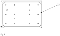
- the seal 22 is provided in the edge area of the carrier plate, here on the circumference, and completely encloses it (cf. figure 7 ). As in figure 3 can be seen, it has a cavity 25 which can be connected to a positive and/or negative pressure source.
- the cavity can be filled with air, oil or water, preferably with the protective gas that is also included in the packaging.
- the contact surface of the seal 22 to the frame 27 can have a profile, which is also shown in figure 3 you can see.
Landscapes
- Engineering & Computer Science (AREA)
- Mechanical Engineering (AREA)
- Physics & Mathematics (AREA)
- Fluid Mechanics (AREA)
- Chemical & Material Sciences (AREA)
- Dispersion Chemistry (AREA)
- Closing Of Containers (AREA)
- Containers And Plastic Fillers For Packaging (AREA)
- Vacuum Packaging (AREA)
- Golf Clubs (AREA)
- Chair Legs, Seat Parts, And Backrests (AREA)
- Sealing Devices (AREA)
Description
Die vorliegende Erfindung betrifft eine Verpackungsmaschine mit einer Siegelstation und einer Schneideeinrichtung, mit der Verpackungen für Verpackungsgüter hergestellt werden, wobei die Siegelstation ein Unter- und/oder Oberwerkzeug mit mindestens einem beweglichen Teil, mit dem das Volumen einer Matrize veränderbar ist, aufweist.The present invention relates to a packaging machine with a sealing station and a cutting device, with which packaging for packaged goods is produced, the sealing station having a lower and/or upper tool with at least one movable part with which the volume of a die can be changed.
Derartige Verpackungsmaschinen sind aus dem Stand der Technik bekannt und werden meist als sogenannte "Form-Fill-Seal-Verpackungsmaschinen" (FFS-Verpackungsmaschinen) bezeichnet (beispielsweise aus
Es besteht seit langem deshalb ein Bedarf, eine Verpackungsmaschine zur Verfügung zu stellen, die die Nachteile des Standes der Technik nicht aufweist.There has therefore long been a need to provide a packaging machine which does not have the disadvantages of the prior art.
Gelöst wird die Aufgabe mit einer Verpackungsmaschine gemäß Patentanspruch 1.The problem is solved with a packaging machine according to
Die vorliegende Erfindung betrifft eine Verpackungsmaschine zum Verpacken von einem Verpackungsgut, insbesondere einem Lebensmittel, vorzugsweise in einer Kunststofffolie, die auch mehrlagig und aus verschiedenen Werkstoffen bestehend ausgeführt sein kann. Die Verpackung weist eine tiefgezogene Verpackungsmulde auf, die mit dem Verpackungsgut befüllt und dann mit einem Deckel, insbesondere einer Deckelfolie verschlossen wird. Die Deckelfolie wird an die Verpackungsmulde gesiegelt. Vor dem Siegeln kann in der Verpackungsmulde ein Gasaustausch vorgenommen werden. Die Deckelfolie kann ebenfalls tiefgezogen sein. Für den Gasaustausch wird die in der noch nicht verschlossenen Verpackung vorhandene Luft teilweise abgesaugt und dadurch ein Unterdruck in der Verpackung erzeugt, der dann oder gleichzeitig durch ein anderes Gas, beispielsweise Sauerstoff, Stickstoff und/oder Kohlendioxid, ersetzt wird, wobei der Gasaustausch in der Regel in und/oder vor der Siegelstation und vor bzw. vorzugsweise nach dem Befüllen der Verpackungsmulde mit Verpackungsgut stattfindet.The present invention relates to a packaging machine for packaging a product to be packaged, in particular a foodstuff, preferably in a plastic film, which can also be multi-layered and made of different materials. The packaging has a deep-drawn packaging tray that is filled with the packaged goods and then closed with a lid, in particular a lid film. The lid film is sealed to the packaging tray. A gas exchange can be carried out in the packaging tray before sealing. The cover film can also be thermoformed. For the gas exchange, the air present in the not yet sealed packaging is partially sucked out and a negative pressure is thereby generated in the packaging, which is then or simultaneously replaced by another gas, for example oxygen, nitrogen and/or carbon dioxide, with the gas exchange taking place in the Usually takes place in and / or before the sealing station and before or preferably after the filling of the packaging tray with packaged goods.
Die erfindungsgemäße Verpackungsmaschine weist folglich eine Siegelstation auf, die jeweils über ein Unter- und/oder ein Oberwerkzeug verfügen, wobei das Unterwerkzeug unterhalb und das Oberwerkzeug oberhalb der Transportebene der Folienbahn, aus der die Verpackungsmulde geformt wird, angeordnet ist. Mindestens eines dieser Werkzeuge weist eine Matrize auf, in die die Unterfolie oder die Deckfolie tiefgezogen wird, bzw. die tiefgezogene Form beim Siegeln aufnimmt. In der Regel sind in dem Werkzeug eine Vielzahl von Matrizen vorgesehen, in die jeweils eine Verpackungsmulde oder eine Deckelmulde eingeformt wird, bzw. die jeweils eine Verpackungsmulde oder Deckelmulde beim Siegeln aufnehmen.The packaging machine according to the invention consequently has a sealing station, each of which has a lower and/or upper tool, with the lower tool being arranged below and the upper tool being arranged above the transport plane of the film web from which the packaging tray is formed. At least one of these tools has a die into which the bottom film or the cover film is deep-drawn or which receives the deep-drawn shape during sealing. As a rule, a large number of matrices are provided in the tool, in each of which a packaging cavity or a lid cavity is formed, or which each receive a packaging cavity or lid cavity during sealing.
Erfindungsgemäß weist mindestens ein Werkzeug mindestens ein bewegliches Teil auf, mit dem das Volumen der Matrize veränderbar ist. Weiterhin erfindungsgemäß ist dieses bewegliche Teil in seinem Randbereich abgedichtet. Vorzugsweise wirkt diese Dichtung einerseits dichtend an dem beweglichen Teil und anderseits dichtend, beispielsweise mit dem Rahmen und/oder der Brille des jeweiligen Werkzeugs zusammenwirken. Durch die Dichtung wird ein Teil des Volumens des Werkzeugs von einer Unter- und/oder Überdruckquelle, an die das jeweilige Werkzeug angeschlossen ist abgeriegelt, so dass es an Druckveränderungen nicht mehr teilnimmt. Die Dichtung ist dabei an dem beweglichen Teil angeordnet.According to the invention, at least one tool has at least one movable part with which the volume of the die can be changed. Furthermore, according to the invention, this movable part is sealed in its edge area. This seal preferably has a sealing effect on the movable part on the one hand and a sealing effect on the other hand, for example interacting with the frame and/or the seat of the respective tool. The seal seals off part of the volume of the tool from a negative and/or positive pressure source to which the respective tool is connected, so that it no longer participates in pressure changes. The seal is arranged on the moving part.
Vorzugsweise ist der Querschnitt der Dichtung veränderbar. Dafür ist die Dichtung vorzugsweise zumindest teilweise hohl vorgesehen. Der Hohlraum kann wahlweise evakuiert oder mit Überdruck versehen werden. Dadurch kann die Dichtung wahlweise eine dichtende Funktion einnehmen oder nicht. Wird die Ziehtiefenverstellung beispielsweise über eine Maschinensteuerung aktiviert, wird die Dichtung entspannt, beispielwei-se entlüftet, insbesondere selbsttätig entlüftet oder die Entlüftung wird mit Vakuum unterstützt. Danach wird die gewünschte Stellung des verschieblichen Teils angefahren. Ist der eingestellte Wert erreicht, wird die Dichtung beispielsweise mit Wasser, Öl oder Luft, vorzugsweise mit dem auch in der Verpackung eingebrachten Schutzgas, unter Druck gesetzt, so dass sich ihr Querschnitt erweitert. Die Dichtung dichtet dann den jeweiligen Spalt zwischen dem beweglichen Teil und dem Unter- oder Oberwerkzeug ab. Diese Abdichtung wird dann über die folgenden Prozesse aufrecht gehalten. Erst bei einer erneuten Verstellung wird die Dichtung wieder entlastet. Im Falle einer Undichtigkeit der Dichtung, z. B. infolge Beschädigung, ist bei Verwendung von Schutzgas als Druckmedium die Qualität der Atmosphäre in der Verpackung sichergestellt.The cross section of the seal is preferably variable. For this purpose, the seal is preferably at least partially hollow. The cavity can either be evacuated or pressurized. As a result, the seal can either take on a sealing function or not. If the drawing depth adjustment is activated via a machine control, for example, the seal is relaxed, for example vented, in particular vented automatically or venting is supported with vacuum. Then the desired position of the movable part is approached. Once the set value has been reached, the seal is pressurized with water, oil or air, for example, preferably with the protective gas that is also included in the packaging, so that its cross-section expands. The seal then seals the respective gap between the moving part and the lower or upper tool. This seal is then maintained through the following processes. The seal is only relieved again when the adjustment is made again. In the event of a leak in the seal, e.g. B. due to damage, the quality of the atmosphere in the packaging is ensured when using inert gas as the pressure medium.
Ein weiterer bevorzugter Gegenstand der vorliegenden Erfindung beinhaltet das Überprüfen des in der Dichtung oder im Dichtsystem anliegenden Drucks, um so auf eine potentielle Leckage z. B. infolge einer Beschädigung der Dichtung schließen zu können bzw. diese zu detektieren.A further preferred object of the present invention involves checking the pressure present in the seal or in the sealing system in order to detect a potential leakage e.g. B. to be able to close or to detect this due to damage to the seal.
Vorzugsweise ist der bewegliche Teil direkt oder indirekt motorisch angetrieben. Zwischen dem Antrieb und dem beweglichen Teil kann ein Getriebe, beispielsweise ein Kniehebelgetriebe, vorgesehen sein. Der Antrieb kann beispielsweise ein Linear- oder Drehantrieb sein. Der Antrieb ist vorzugsweise mit einer Maschinensteuerung verbunden und wird von dieser geregelt. Dadurch kann die gewünschte Position des beweglichen Teils automatisch angefahren und dadurch die gewünschte Packungstiefe automatisch eingestellt werden. Der Antrieb stützt sich vorzugsweise an dem Rahmen des Werkzeugs ab. Vorzugsweise ist der Motor so vorgesehen, dass die Steuerung/Regelung zu jedem Zeitpunkt weiß, in welcher Position sich das bewegliche Teil befindet.The moving part is preferably driven directly or indirectly by a motor. A gear, for example a toggle lever gear, can be provided between the drive and the movable part. The drive can be a linear or rotary drive, for example. The drive is preferably connected to a machine controller and is regulated by it. As a result, the desired position of the moving part can be approached automatically and the desired pack depth can be set automatically as a result. The drive is preferably supported on the frame of the tool. The motor is preferably provided in such a way that the control/regulation knows the position of the movable part at all times.
Der Antrieb befindet sich vorzugsweise innerhalb des Rahmens des Werkzeugs; alternativ befindet sich der Antrieb außerhalb des Werkzeugs, beispielsweise bei Platzmangel, wobei der Bereich, in dem zumindest ein Teil der beweglichen Antriebsmechanik, beispielsweise Schubstangen, durch die Wandung des Rahmens des Werkzeugs durchgeführt wird gleichermaßen erfindungsgemäße Dichtmittel aufweist; hiernach ist auch dieser Bereich der Durchführung durch den Rahmen gezielt abdichtbar.The drive is preferably located within the frame of the tool; alternatively, the drive is located outside the tool, for example when there is a lack of space, the area in which at least part of the movable drive mechanism, for example push rods, is guided through the wall of the frame of the tool also having sealing means according to the invention; after this, this area of the leadthrough can also be sealed off in a targeted manner by the frame.
Ein Antrieb, beispielsweise eine oder mehrere Schubstangen werden auch dazu verwendet, um vorzugsweise bei schweren oder empfindlichen Verpackungsgütern die befüllten Packungen z. B. in der Siegelstation zu unterstützen; der Antrieb, beispielsweise die bewegliche(n) Schubstange(n), dieser sogenannten einstellbaren Produktunterstützung wird vorzugsweise mit dem beschriebenen Dichtmittel beispielsweise im Bereich der Durchführung durch den Rahmen abgedichtet.A drive, for example, one or more push rods are also used to move the filled packs, e.g. B. to support in the sealing station; the drive, for example the movable push rod(s), of this so-called adjustable product support is preferably sealed with the described sealing means, for example in the area of the passage through the frame.
Vorzugsweise ist die Schubstange eines Antriebs zumindest bereichsweise hohl, um durch diesen holen Kanal das Werkzeug mit Versorgungsmedien, beispielsweise Kühlwasser oder Signalkabel zu versorgen. Um die Schubstangen vor mechanischer Überlastung zu schützen wird der Antrieb vorzugsweise innerhalb des Rahmens des Werkzeugs realisiert.The push rod of a drive is preferably hollow at least in some areas in order to supply the tool with supply media, for example cooling water or signal cables, through this hollow channel. In order to protect the push rods from mechanical overload, the drive is preferably implemented within the frame of the tool.
Im Folgenden wird die Erfindung anhand der Figuren erläutert. Diese Erläuterungen sind lediglich beispielhaft und schränken den allgemeinen Erfindungsgedanken nicht ein. Die Erläuterungen gelten für alle Gegenstände der vorliegenden Erfindung gleichermaßen.
Figur 1- zeigt die erfindungsgemäße Verpackungsmaschine
Figur 2- zeigt das Werkzeug, hier ein Tiefziehwerkzeug
Figur 3- zeigt die Dichtung
Figur 4- zeigt das Werkzeug im nicht abgedichteten Zustand
Figur 5- zeigt das Werkzeug im abgedichteten Zustand
Figuren 6 und 7- zeigen eine um das bewegliche Teil umlaufende Dichtung
- figure 1
- shows the packaging machine according to the invention
- figure 2
- shows the tool, here a deep-drawing tool
- figure 3
- shows the seal
- figure 4
- shows the tool in unsealed condition
- figure 5
- shows the tool in sealed condition
- Figures 6 and 7
- show a seal surrounding the moving part
Bevor eine Verstellung der Trägerplatte 24 relativ zu dem Rahmen 27 erfolgt, wird die Dichtung 22 entspannt oder in ihrem Querschnitt zusammengezogen, was in
Die Dichtung 22 ist im Randbereich der Trägerplatte, hier am Umfang vorgesehen und umschließt diesen vollständig (vgl.
- 11
- Verpackungsmaschinepackaging machine
- 22
- Tiefziehstationthermoforming station
- 33
- Oberwerkzeug der TiefziehstationUpper tool of the deep-drawing station
- 44
- Unterwerkzeug der TiefziehstationLower tool of the deep-drawing station
- 55
- Hubtisch, Träger eines Werkzeugs der Siegel- , Tiefziehstation und/oder der SchneideinrichtungElevating table, carrier of a tool for the sealing, deep-drawing station and/or the cutting device
- 66
- Verpackungsmuldepackaging tray
- 77
- Füllstationfilling station
- 88th
- Unterfolienbahnlower web
- 99
- Hubeinrichtunglifting device
- 1010
- Antriebdrive
- 1111
- Unterwerkzeug der SiegelstationLower tool of the sealing station
- 1212
- Oberwerkzeug der SiegelstationUpper tool of the sealing station
- 1313
- Kolbenstangepiston rod
- 1414
- Oberfolietop film
- 1515
- Siegelstationsealing station
- 1616
- Verpackungsgutpackaged goods
- 1717
- Längsschneiderslitter
- 1818
- Querschneidersheeter
- 1919
- Einlaufbereichinlet area
- 2020
- bewegliches Teil, Formschalemoving part, molded shell
- 2121
- Matrizedie
- 2222
- Dichtungpoetry
- 2323
- Randbereichedge area
- 2424
- Trägerplattebacking plate
- 2525
- LeitungManagement
- 2626
- Über- und/oder UnterdruckquelleSource of positive and/or negative pressure
- 2727
- RahmenFrame
- 2828
- Antriebdrive
- 2929
- Hohlraumcavity
- 3030
- Brille (Siegelwerkzeug); Formwerkzeugglasses (sealing tool); molding tool
Claims (5)
- Packaging machine (1) having a sealing station (15) and a cutting device (17, 18), with which packs for goods to be packed are produced, wherein the sealing station (15) has a lower and/or upper mould (11, 12) with at least one movable part (24), with which the volume of a die (21) can be varied, wherein the movable part (24) is a carrier plate (24) on which at least one mould shell (20) is provided, characterized in that the edge region of the movable part (24) of the sealing mould is sealed off with a seal (22) such that part of the volume of the mould is sealed off by a negative and/or positive pressure source, to which the respective mould is connected.
- Packaging machine (1) according to Claim 1, characterized in that the cross section of the seal can be varied.
- Packaging machine (1) according to one of the preceding claims, characterized in that the movable part (20) is directly or indirectly motor-driven, wherein the drive is preferably at least partly sealed off, in particular with respect to the mould.
- Packaging machine (1) according to one of the preceding claims, characterized in that the seal is connected to a positive and/or negative pressure source (26).
- Packaging machine (1) according to one of the preceding claims, characterized in that it has a sensor which checks the pressure in the seal.
Applications Claiming Priority (2)
| Application Number | Priority Date | Filing Date | Title |
|---|---|---|---|
| DE102015223608 | 2015-11-27 | ||
| PCT/EP2016/078861 WO2017089572A1 (en) | 2015-11-27 | 2016-11-25 | Reduction of the chamber volume during drawing-depth adaptation in the moulding and sealing station by means of an inflatable seal |
Publications (3)
| Publication Number | Publication Date |
|---|---|
| EP3380405A1 EP3380405A1 (en) | 2018-10-03 |
| EP3380405B1 EP3380405B1 (en) | 2020-01-01 |
| EP3380405B2 true EP3380405B2 (en) | 2023-03-15 |
Family
ID=57394602
Family Applications (1)
| Application Number | Title | Priority Date | Filing Date |
|---|---|---|---|
| EP16801264.9A Active EP3380405B2 (en) | 2015-11-27 | 2016-11-25 | Reduction of the chamber volume during drawing-depth adaptation in the sealing station by means of an inflatable seal |
Country Status (4)
| Country | Link |
|---|---|
| EP (1) | EP3380405B2 (en) |
| BR (1) | BR112018010729B1 (en) |
| ES (1) | ES2778681T5 (en) |
| WO (1) | WO2017089572A1 (en) |
Families Citing this family (2)
| Publication number | Priority date | Publication date | Assignee | Title |
|---|---|---|---|---|
| CN109291412A (en) * | 2018-12-05 | 2019-02-01 | 中山市兰佳机械设备有限公司 | A kind of tab system of vacuum plastic-absorbing machine |
| WO2023078918A1 (en) * | 2021-11-05 | 2023-05-11 | Gea Food Solutions Germany Gmbh | Packaging machine having a cooled molding tool |
Family Cites Families (19)
| Publication number | Priority date | Publication date | Assignee | Title |
|---|---|---|---|---|
| US2601020A (en) | 1949-01-27 | 1952-06-17 | Standard Cap & Seal Corp | Apparatus for packaging materials |
| US3299608A (en) * | 1963-08-29 | 1967-01-24 | Oscar Mayer & Company Inc | Packaging machine |
| US5323590A (en) * | 1986-09-03 | 1994-06-28 | Seawell North America, Inc. | Method of producing food packaging with gas between tensioned film and lid |
| FR2622171B1 (en) | 1987-10-27 | 1990-12-14 | Mecaplastic | PROCESS AND APPARATUS FOR PACKAGING FOOD OR OTHER PRODUCT IN A PRESENTATION TRAY |
| GB2239229A (en) | 1989-12-22 | 1991-06-26 | Grace W R & Co | Vacuum packaging apparatus |
| FR2725692B1 (en) | 1994-10-17 | 1997-01-24 | Automatisme Assistance | PROCESS FOR SEALING RIGID CONTAINERS UNDER FILM FOR VACUUM OR MODIFIED ATMOSPHERE PACKAGING OF FOOD PRODUCTS, AND DEVICE FOR IMPLEMENTING SAME |
| US5637812A (en) | 1994-11-14 | 1997-06-10 | Screening Systems, Inc. | Variable volume test chamber |
| EP1021338B1 (en) | 1997-10-06 | 2002-04-03 | ROSSI, Jean-Pierre | Device for packaging products under controlled atmosphere in packages sealed with a film |
| JP3983015B2 (en) | 2000-07-03 | 2007-09-26 | 東京エレクトロン株式会社 | Processing unit with seal mechanism |
| DE20116922U1 (en) | 2001-10-15 | 2002-01-24 | Marbach Werkzeugbau GmbH, 74080 Heilbronn | Thermoforming mold |
| DE10326670B3 (en) | 2003-06-13 | 2004-08-26 | Adolf Illig Maschinenbau Gmbh & Co.Kg | Mold for deep drawing containers, from a thermoplastic film, has a seal in a groove at the stretch former or a piston which is pressed against the hold-down plate drilling by compressed air |
| US20060218884A1 (en) | 2005-03-30 | 2006-10-05 | Sealed Air Corporation | Adjustable infeed bed for packaging apparatus |
| DE102005035476B4 (en) | 2005-07-26 | 2022-07-07 | Jörg von Seggern Maschinenbau GmbH | Device for gas-tight packaging of objects |
| DE102006045327A1 (en) | 2006-09-22 | 2008-04-03 | Cfs Germany Gmbh | Heating plate with a variety of heating cartridges |
| DE102007037748B3 (en) | 2007-08-10 | 2008-10-23 | Illig Maschinenbau Gmbh & Co. Kg | Forming tool for use in deep-drawing of containers has lower section with forming insert and needle holder in the upper section with slidable and sealable piston |
| DE102010009536A1 (en) | 2010-02-26 | 2011-09-01 | Cfs Germany Gmbh | Method for changing the upper and lower tool of a packaging machine |
| ES2541864T3 (en) | 2011-01-27 | 2015-07-27 | Gea Food Solutions Germany Gmbh | Packaging machine and procedure for manufacturing vacuum and / or gasified containers |
| CH709373A2 (en) | 2015-07-10 | 2015-08-28 | V Zug Ag | Vacuum Sealer with welding bar cover. |
| EP3279096B1 (en) | 2015-09-14 | 2019-06-12 | Miele & Cie. KG | Vacuuming device and method and kitchen appliance and drawer device with a vacuuming device |
-
2016
- 2016-11-25 WO PCT/EP2016/078861 patent/WO2017089572A1/en active Application Filing
- 2016-11-25 BR BR112018010729-8A patent/BR112018010729B1/en active IP Right Grant
- 2016-11-25 ES ES16801264T patent/ES2778681T5/en active Active
- 2016-11-25 EP EP16801264.9A patent/EP3380405B2/en active Active
Also Published As
| Publication number | Publication date |
|---|---|
| BR112018010729A8 (en) | 2019-02-26 |
| ES2778681T5 (en) | 2023-07-13 |
| WO2017089572A1 (en) | 2017-06-01 |
| EP3380405B1 (en) | 2020-01-01 |
| BR112018010729A2 (en) | 2018-11-13 |
| BR112018010729B1 (en) | 2022-05-31 |
| ES2778681T3 (en) | 2020-08-11 |
| EP3380405A1 (en) | 2018-10-03 |
Similar Documents
| Publication | Publication Date | Title |
|---|---|---|
| EP2989011B1 (en) | Valve for low/high vacuum integrated in tool | |
| EP0023264B1 (en) | Packaging machine | |
| EP2746167B1 (en) | Deep draw packaging machine with hoisting gear powered by an electric motor | |
| EP2960165B1 (en) | Deep drawing packaging machine and method | |
| DE102004051923B4 (en) | Sealing station on a packaging machine having one or more individually manageable sealing cassettes | |
| WO2012100956A1 (en) | Packaging machine and method for producing evacuated and/or gassed packagings | |
| EP2644516A1 (en) | Packaging machine with a sealing device | |
| US20100011718A1 (en) | Packaging machine having an adjustable pneumatic/hydraulic drive | |
| EP3380405B2 (en) | Reduction of the chamber volume during drawing-depth adaptation in the sealing station by means of an inflatable seal | |
| DE102012018974A1 (en) | Thermo-formed packaging machine has molding station, where molding station comprises mold upper portion, mold lower portion and molding punch, and molding punch and mold lower portion are designed such that they have inner molding chamber | |
| EP3390234B1 (en) | Mold comprising a split mold shell | |
| EP2800699B1 (en) | Packaging machine having a cutting station | |
| WO2016207059A1 (en) | Packaging machine having a motorized throttle | |
| DE102010019576B4 (en) | Packaging machine with an exchangeable drive for the lifting device | |
| WO2008043572A1 (en) | Tool comprising a linear drive | |
| EP3294636B1 (en) | Packaging machine having a lifting device | |
| WO2015169830A1 (en) | Packaging machine with vacuum control module consisting of uniform valve blocks | |
| DE202004016538U1 (en) | Sealing station for packing machines has upper and lower sections which can be moved together to seal articles between sheets, cassette being mounted in upper section containing heated plate which can be raised and lowered | |
| EP3230166B1 (en) | Method for arranging two coatings on a cover film | |
| DE102017101210A1 (en) | Packaging machine with a lifting device | |
| WO2017102541A1 (en) | Packaging machine and method for producing evacuated packagings | |
| DE1997665U (en) | DEVICE FOR MANUFACTURING PACKAGING CONTAINERS | |
| WO2024074541A1 (en) | Sealing tool for a skin packaging | |
| WO2022084235A2 (en) | Longitudinal nozzle arrangement | |
| DE102018111600A1 (en) | METHOD FOR DETECTING LEAKAGE |
Legal Events
| Date | Code | Title | Description |
|---|---|---|---|
| STAA | Information on the status of an ep patent application or granted ep patent |
Free format text: STATUS: UNKNOWN |
|
| STAA | Information on the status of an ep patent application or granted ep patent |
Free format text: STATUS: THE INTERNATIONAL PUBLICATION HAS BEEN MADE |
|
| PUAI | Public reference made under article 153(3) epc to a published international application that has entered the european phase |
Free format text: ORIGINAL CODE: 0009012 |
|
| STAA | Information on the status of an ep patent application or granted ep patent |
Free format text: STATUS: REQUEST FOR EXAMINATION WAS MADE |
|
| 17P | Request for examination filed |
Effective date: 20180528 |
|
| AK | Designated contracting states |
Kind code of ref document: A1 Designated state(s): AL AT BE BG CH CY CZ DE DK EE ES FI FR GB GR HR HU IE IS IT LI LT LU LV MC MK MT NL NO PL PT RO RS SE SI SK SM TR |
|
| AX | Request for extension of the european patent |
Extension state: BA ME |
|
| DAV | Request for validation of the european patent (deleted) | ||
| DAX | Request for extension of the european patent (deleted) | ||
| STAA | Information on the status of an ep patent application or granted ep patent |
Free format text: STATUS: EXAMINATION IS IN PROGRESS |
|
| 17Q | First examination report despatched |
Effective date: 20190322 |
|
| GRAP | Despatch of communication of intention to grant a patent |
Free format text: ORIGINAL CODE: EPIDOSNIGR1 |
|
| STAA | Information on the status of an ep patent application or granted ep patent |
Free format text: STATUS: GRANT OF PATENT IS INTENDED |
|
| INTG | Intention to grant announced |
Effective date: 20190730 |
|
| GRAS | Grant fee paid |
Free format text: ORIGINAL CODE: EPIDOSNIGR3 |
|
| GRAA | (expected) grant |
Free format text: ORIGINAL CODE: 0009210 |
|
| STAA | Information on the status of an ep patent application or granted ep patent |
Free format text: STATUS: THE PATENT HAS BEEN GRANTED |
|
| AK | Designated contracting states |
Kind code of ref document: B1 Designated state(s): AL AT BE BG CH CY CZ DE DK EE ES FI FR GB GR HR HU IE IS IT LI LT LU LV MC MK MT NL NO PL PT RO RS SE SI SK SM TR |
|
| REG | Reference to a national code |
Ref country code: GB Ref legal event code: FG4D Free format text: NOT ENGLISH |
|
| REG | Reference to a national code |
Ref country code: CH Ref legal event code: EP Ref country code: AT Ref legal event code: REF Ref document number: 1219524 Country of ref document: AT Kind code of ref document: T Effective date: 20200115 |
|
| REG | Reference to a national code |
Ref country code: IE Ref legal event code: FG4D Free format text: LANGUAGE OF EP DOCUMENT: GERMAN |
|
| REG | Reference to a national code |
Ref country code: DE Ref legal event code: R096 Ref document number: 502016008285 Country of ref document: DE |
|
| REG | Reference to a national code |
Ref country code: NL Ref legal event code: FP |
|
| REG | Reference to a national code |
Ref country code: LT Ref legal event code: MG4D |
|
| PG25 | Lapsed in a contracting state [announced via postgrant information from national office to epo] |
Ref country code: RS Free format text: LAPSE BECAUSE OF FAILURE TO SUBMIT A TRANSLATION OF THE DESCRIPTION OR TO PAY THE FEE WITHIN THE PRESCRIBED TIME-LIMIT Effective date: 20200101 Ref country code: LT Free format text: LAPSE BECAUSE OF FAILURE TO SUBMIT A TRANSLATION OF THE DESCRIPTION OR TO PAY THE FEE WITHIN THE PRESCRIBED TIME-LIMIT Effective date: 20200101 Ref country code: PT Free format text: LAPSE BECAUSE OF FAILURE TO SUBMIT A TRANSLATION OF THE DESCRIPTION OR TO PAY THE FEE WITHIN THE PRESCRIBED TIME-LIMIT Effective date: 20200527 Ref country code: CZ Free format text: LAPSE BECAUSE OF FAILURE TO SUBMIT A TRANSLATION OF THE DESCRIPTION OR TO PAY THE FEE WITHIN THE PRESCRIBED TIME-LIMIT Effective date: 20200101 Ref country code: FI Free format text: LAPSE BECAUSE OF FAILURE TO SUBMIT A TRANSLATION OF THE DESCRIPTION OR TO PAY THE FEE WITHIN THE PRESCRIBED TIME-LIMIT Effective date: 20200101 Ref country code: NO Free format text: LAPSE BECAUSE OF FAILURE TO SUBMIT A TRANSLATION OF THE DESCRIPTION OR TO PAY THE FEE WITHIN THE PRESCRIBED TIME-LIMIT Effective date: 20200401 |
|
| REG | Reference to a national code |
Ref country code: ES Ref legal event code: FG2A Ref document number: 2778681 Country of ref document: ES Kind code of ref document: T3 Effective date: 20200811 |
|
| PG25 | Lapsed in a contracting state [announced via postgrant information from national office to epo] |
Ref country code: GR Free format text: LAPSE BECAUSE OF FAILURE TO SUBMIT A TRANSLATION OF THE DESCRIPTION OR TO PAY THE FEE WITHIN THE PRESCRIBED TIME-LIMIT Effective date: 20200402 Ref country code: BG Free format text: LAPSE BECAUSE OF FAILURE TO SUBMIT A TRANSLATION OF THE DESCRIPTION OR TO PAY THE FEE WITHIN THE PRESCRIBED TIME-LIMIT Effective date: 20200401 Ref country code: HR Free format text: LAPSE BECAUSE OF FAILURE TO SUBMIT A TRANSLATION OF THE DESCRIPTION OR TO PAY THE FEE WITHIN THE PRESCRIBED TIME-LIMIT Effective date: 20200101 Ref country code: SE Free format text: LAPSE BECAUSE OF FAILURE TO SUBMIT A TRANSLATION OF THE DESCRIPTION OR TO PAY THE FEE WITHIN THE PRESCRIBED TIME-LIMIT Effective date: 20200101 Ref country code: IS Free format text: LAPSE BECAUSE OF FAILURE TO SUBMIT A TRANSLATION OF THE DESCRIPTION OR TO PAY THE FEE WITHIN THE PRESCRIBED TIME-LIMIT Effective date: 20200501 Ref country code: LV Free format text: LAPSE BECAUSE OF FAILURE TO SUBMIT A TRANSLATION OF THE DESCRIPTION OR TO PAY THE FEE WITHIN THE PRESCRIBED TIME-LIMIT Effective date: 20200101 |
|
| REG | Reference to a national code |
Ref country code: DE Ref legal event code: R026 Ref document number: 502016008285 Country of ref document: DE |
|
| PLBI | Opposition filed |
Free format text: ORIGINAL CODE: 0009260 |
|
| PLAX | Notice of opposition and request to file observation + time limit sent |
Free format text: ORIGINAL CODE: EPIDOSNOBS2 |
|
| PG25 | Lapsed in a contracting state [announced via postgrant information from national office to epo] |
Ref country code: SK Free format text: LAPSE BECAUSE OF FAILURE TO SUBMIT A TRANSLATION OF THE DESCRIPTION OR TO PAY THE FEE WITHIN THE PRESCRIBED TIME-LIMIT Effective date: 20200101 Ref country code: RO Free format text: LAPSE BECAUSE OF FAILURE TO SUBMIT A TRANSLATION OF THE DESCRIPTION OR TO PAY THE FEE WITHIN THE PRESCRIBED TIME-LIMIT Effective date: 20200101 Ref country code: DK Free format text: LAPSE BECAUSE OF FAILURE TO SUBMIT A TRANSLATION OF THE DESCRIPTION OR TO PAY THE FEE WITHIN THE PRESCRIBED TIME-LIMIT Effective date: 20200101 Ref country code: SM Free format text: LAPSE BECAUSE OF FAILURE TO SUBMIT A TRANSLATION OF THE DESCRIPTION OR TO PAY THE FEE WITHIN THE PRESCRIBED TIME-LIMIT Effective date: 20200101 Ref country code: EE Free format text: LAPSE BECAUSE OF FAILURE TO SUBMIT A TRANSLATION OF THE DESCRIPTION OR TO PAY THE FEE WITHIN THE PRESCRIBED TIME-LIMIT Effective date: 20200101 |
|
| 26 | Opposition filed |
Opponent name: MULTIVAC SEPP HAGGENMUELLER SE & CO. KG Effective date: 20200925 |
|
| PLBB | Reply of patent proprietor to notice(s) of opposition received |
Free format text: ORIGINAL CODE: EPIDOSNOBS3 |
|
| PG25 | Lapsed in a contracting state [announced via postgrant information from national office to epo] |
Ref country code: SI Free format text: LAPSE BECAUSE OF FAILURE TO SUBMIT A TRANSLATION OF THE DESCRIPTION OR TO PAY THE FEE WITHIN THE PRESCRIBED TIME-LIMIT Effective date: 20200101 Ref country code: PL Free format text: LAPSE BECAUSE OF FAILURE TO SUBMIT A TRANSLATION OF THE DESCRIPTION OR TO PAY THE FEE WITHIN THE PRESCRIBED TIME-LIMIT Effective date: 20200101 |
|
| PG25 | Lapsed in a contracting state [announced via postgrant information from national office to epo] |
Ref country code: MC Free format text: LAPSE BECAUSE OF FAILURE TO SUBMIT A TRANSLATION OF THE DESCRIPTION OR TO PAY THE FEE WITHIN THE PRESCRIBED TIME-LIMIT Effective date: 20200101 |
|
| GBPC | Gb: european patent ceased through non-payment of renewal fee |
Effective date: 20201125 |
|
| PG25 | Lapsed in a contracting state [announced via postgrant information from national office to epo] |
Ref country code: LU Free format text: LAPSE BECAUSE OF NON-PAYMENT OF DUE FEES Effective date: 20201125 |
|
| REG | Reference to a national code |
Ref country code: BE Ref legal event code: MM Effective date: 20201130 |
|
| PG25 | Lapsed in a contracting state [announced via postgrant information from national office to epo] |
Ref country code: IE Free format text: LAPSE BECAUSE OF NON-PAYMENT OF DUE FEES Effective date: 20201125 |
|
| PG25 | Lapsed in a contracting state [announced via postgrant information from national office to epo] |
Ref country code: GB Free format text: LAPSE BECAUSE OF NON-PAYMENT OF DUE FEES Effective date: 20201125 |
|
| PG25 | Lapsed in a contracting state [announced via postgrant information from national office to epo] |
Ref country code: MT Free format text: LAPSE BECAUSE OF FAILURE TO SUBMIT A TRANSLATION OF THE DESCRIPTION OR TO PAY THE FEE WITHIN THE PRESCRIBED TIME-LIMIT Effective date: 20200101 Ref country code: CY Free format text: LAPSE BECAUSE OF FAILURE TO SUBMIT A TRANSLATION OF THE DESCRIPTION OR TO PAY THE FEE WITHIN THE PRESCRIBED TIME-LIMIT Effective date: 20200101 |
|
| PG25 | Lapsed in a contracting state [announced via postgrant information from national office to epo] |
Ref country code: MK Free format text: LAPSE BECAUSE OF FAILURE TO SUBMIT A TRANSLATION OF THE DESCRIPTION OR TO PAY THE FEE WITHIN THE PRESCRIBED TIME-LIMIT Effective date: 20200101 Ref country code: AL Free format text: LAPSE BECAUSE OF FAILURE TO SUBMIT A TRANSLATION OF THE DESCRIPTION OR TO PAY THE FEE WITHIN THE PRESCRIBED TIME-LIMIT Effective date: 20200101 |
|
| PG25 | Lapsed in a contracting state [announced via postgrant information from national office to epo] |
Ref country code: BE Free format text: LAPSE BECAUSE OF NON-PAYMENT OF DUE FEES Effective date: 20201130 |
|
| PUAH | Patent maintained in amended form |
Free format text: ORIGINAL CODE: 0009272 |
|
| STAA | Information on the status of an ep patent application or granted ep patent |
Free format text: STATUS: PATENT MAINTAINED AS AMENDED |
|
| 27A | Patent maintained in amended form |
Effective date: 20230315 |
|
| AK | Designated contracting states |
Kind code of ref document: B2 Designated state(s): AL AT BE BG CH CY CZ DE DK EE ES FI FR GB GR HR HU IE IS IT LI LT LU LV MC MK MT NL NO PL PT RO RS SE SI SK SM TR |
|
| REG | Reference to a national code |
Ref country code: DE Ref legal event code: R102 Ref document number: 502016008285 Country of ref document: DE |
|
| REG | Reference to a national code |
Ref country code: NL Ref legal event code: FP |
|
| P01 | Opt-out of the competence of the unified patent court (upc) registered |
Effective date: 20230513 |
|
| REG | Reference to a national code |
Ref country code: ES Ref legal event code: DC2A Ref document number: 2778681 Country of ref document: ES Kind code of ref document: T5 Effective date: 20230713 |
|
| PGFP | Annual fee paid to national office [announced via postgrant information from national office to epo] |
Ref country code: NL Payment date: 20231122 Year of fee payment: 8 |
|
| PGFP | Annual fee paid to national office [announced via postgrant information from national office to epo] |
Ref country code: ES Payment date: 20231215 Year of fee payment: 8 |
|
| PGFP | Annual fee paid to national office [announced via postgrant information from national office to epo] |
Ref country code: TR Payment date: 20231116 Year of fee payment: 8 Ref country code: IT Payment date: 20231130 Year of fee payment: 8 Ref country code: FR Payment date: 20231123 Year of fee payment: 8 Ref country code: DE Payment date: 20231120 Year of fee payment: 8 Ref country code: CH Payment date: 20231202 Year of fee payment: 8 Ref country code: AT Payment date: 20231117 Year of fee payment: 8 |