EP3380296B1 - Ventilschaftbetätigung - Google Patents
Ventilschaftbetätigung Download PDFInfo
- Publication number
- EP3380296B1 EP3380296B1 EP16867474.5A EP16867474A EP3380296B1 EP 3380296 B1 EP3380296 B1 EP 3380296B1 EP 16867474 A EP16867474 A EP 16867474A EP 3380296 B1 EP3380296 B1 EP 3380296B1
- Authority
- EP
- European Patent Office
- Prior art keywords
- piston
- valve stem
- actuation plate
- hot runner
- air
- Prior art date
- Legal status (The legal status is an assumption and is not a legal conclusion. Google has not performed a legal analysis and makes no representation as to the accuracy of the status listed.)
- Active
Links
Images


Classifications
-
- B—PERFORMING OPERATIONS; TRANSPORTING
- B29—WORKING OF PLASTICS; WORKING OF SUBSTANCES IN A PLASTIC STATE IN GENERAL
- B29C—SHAPING OR JOINING OF PLASTICS; SHAPING OF MATERIAL IN A PLASTIC STATE, NOT OTHERWISE PROVIDED FOR; AFTER-TREATMENT OF THE SHAPED PRODUCTS, e.g. REPAIRING
- B29C45/00—Injection moulding, i.e. forcing the required volume of moulding material through a nozzle into a closed mould; Apparatus therefor
- B29C45/17—Component parts, details or accessories; Auxiliary operations
- B29C45/26—Moulds
- B29C45/27—Sprue channels ; Runner channels or runner nozzles
- B29C45/28—Closure devices therefor
- B29C45/2806—Closure devices therefor consisting of needle valve systems
- B29C45/281—Drive means therefor
-
- B—PERFORMING OPERATIONS; TRANSPORTING
- B29—WORKING OF PLASTICS; WORKING OF SUBSTANCES IN A PLASTIC STATE IN GENERAL
- B29C—SHAPING OR JOINING OF PLASTICS; SHAPING OF MATERIAL IN A PLASTIC STATE, NOT OTHERWISE PROVIDED FOR; AFTER-TREATMENT OF THE SHAPED PRODUCTS, e.g. REPAIRING
- B29C45/00—Injection moulding, i.e. forcing the required volume of moulding material through a nozzle into a closed mould; Apparatus therefor
- B29C45/17—Component parts, details or accessories; Auxiliary operations
- B29C45/84—Safety devices
-
- B—PERFORMING OPERATIONS; TRANSPORTING
- B29—WORKING OF PLASTICS; WORKING OF SUBSTANCES IN A PLASTIC STATE IN GENERAL
- B29C—SHAPING OR JOINING OF PLASTICS; SHAPING OF MATERIAL IN A PLASTIC STATE, NOT OTHERWISE PROVIDED FOR; AFTER-TREATMENT OF THE SHAPED PRODUCTS, e.g. REPAIRING
- B29C45/00—Injection moulding, i.e. forcing the required volume of moulding material through a nozzle into a closed mould; Apparatus therefor
- B29C45/17—Component parts, details or accessories; Auxiliary operations
- B29C45/26—Moulds
- B29C45/27—Sprue channels ; Runner channels or runner nozzles
- B29C45/28—Closure devices therefor
- B29C45/2806—Closure devices therefor consisting of needle valve systems
- B29C45/281—Drive means therefor
- B29C2045/2813—Common drive means for several needle valves
-
- B—PERFORMING OPERATIONS; TRANSPORTING
- B29—WORKING OF PLASTICS; WORKING OF SUBSTANCES IN A PLASTIC STATE IN GENERAL
- B29C—SHAPING OR JOINING OF PLASTICS; SHAPING OF MATERIAL IN A PLASTIC STATE, NOT OTHERWISE PROVIDED FOR; AFTER-TREATMENT OF THE SHAPED PRODUCTS, e.g. REPAIRING
- B29C2945/00—Indexing scheme relating to injection moulding, i.e. forcing the required volume of moulding material through a nozzle into a closed mould
- B29C2945/76—Measuring, controlling or regulating
- B29C2945/76655—Location of control
- B29C2945/76732—Mould
- B29C2945/76752—Mould runners, nozzles
Definitions
- the disclosed embodiments are generally directed to injection molding machines and more particularly to valve stem actuation.
- Injection molding machines are used to produce plastic molded parts such as, for example, preforms of the type that are blow moldable into beverage containers.
- hot runners include a manifold that delivers hot melt from a sprue bushing to one or more nozzles, which, in turn, deliver the melt to individual cavities of the mold.
- the flow of molding material through the nozzles is controlled by valve stems that are actuated back and forth to open and close gates at the ends of the nozzles.
- the valve stems may be individually actuated by hydraulic, pneumatic or electric actuation arrangements or may be simultaneously actuated via one or more actuation plate(s). Such systems used to simultaneously actuate the valve stems do not provide a satisfactory solution in all aspects.
- a hot runner of an injection molding machine for distributing melt into a mold cavity includes a first valve gated nozzle having a first valve stem, a first piston coupled to the first valve stem, and an actuation plate acting on the first piston and configured to move the first valve stem between an open position and a closed position.
- the first piston is held (biased) against at least a portion of the actuation plate via pressurized air to move with movement of the actuation plate.
- a hot runner of an injection molding machine for passing melt into a mold cavity includes a first valve gated nozzle having a first valve stem, and a first piston coupled to the first valve stem.
- the first piston has a passageway arranged to transfer pressurized air to a chamber.
- the pressurized air biases the valve stem into a closed position.
- An actuation plate acts on the first piston and is configured to move the first valve stem between an open position and a closed position.
- Injection molding machines are used to produce plastic molded parts.
- such machines include a manifold that passes melted molding material, also referred to as melt, to nozzles that, in turn, pass the melt to individual mold cavities.
- melt melted molding material
- the nozzles include valve stems that reciprocate back and forth to open and close gates at the end of the nozzles.
- valve stems may be individually actuated, in some systems, it may be advantageous to simultaneously actuate all of the valve stems at the same time.
- the valve stems may be attached to an actuation plate that reciprocates back and forth to move the valve stems. With simultaneous actuation, if even a single valve stem fails (e.g., becomes stuck in a closed position), the injection molding machine must be shut off to correct the problem.
- individual actuation if a single valve stem fails, the single valve stem may be deactivated while the other valve stems may continue to be actuated.
- valve stems may be arranged to break or shear such that when a valve stem is stuck in the closed position, movement of the plate towards the open position causes the stuck valve stem to break.
- valve stems may be mechanically coupled to the plate via springs that are configured to push the valve stems into the open position (e.g., when an injection cycle has finished) and to compress if a valve stem become stuck in the closed position and the plate is moving towards the opened position.
- the valve stems may be magnetically coupled to the actuation plate and may be configured to decouple from the plate if the valve stems become stuck.
- the hot runner may continue to operate when one or more of the valve stems become stuck in the closed position.
- using pressurized air to maintain contact between the valve stem and the portion of the actuation plate also may allow the valve stem to be protected when the valve stem reciprocates between the open and closed positions and becomes stuck in the closed position and/or encounters an obstruction (e.g., in the mold the cavity).
- embodiments disclosed herein include a hot runner that uses pressurized air to hold the valve stems against the portion of the actuation plate, such as a retainer plate located at the back of the actuation plate, during plate actuation.
- Another technical effect of the air spring connection may include simplified hot runner startup. At startup, prior to start of a molding process, a calibration of the plate actuator must be completed. Calibration is done by cycling the actuation plate several times thereby repositioning the valve stems between closed and open positions. By virtue of the air spring connection the calibration can be done with the hot runner in either a cold or heated state. Specifically, the air supply to the air spring can be disabled to allow the operator to calibrate in either cold condition or hot condition for added convenience.
- valve stems In the hot condition with the air disabled, the valve stems will remain in closed position as the actuation plate is calibrated. Advantages of the foregoing may include reduced risk of drool flowing into the cavities because the valve stems remain closed thereby alleviating the additional requirement for the operator to remove solidified drool from cavities prior to startup of process and thereby save time.
- holding the valve stem against the portion of the actuation plate may mean that the valve stem (or an extension thereof) is pressed against the portion of the actuation plate or otherwise biased to a predetermined position relative thereto during plate actuation.
- the valve stems may directly contact the actuation plate.
- the valve stems may indirectly contact the actuation plate (e.g., via pistons).
- the valve stem may be pressed in an upward direction relative to the actuation plate (i.e., towards the open position).
- holding the valve stem against the portion of the actuation plate may mean that the position of the valve stem is maintained relative to the position of the actuation plate during plate actuation.
- the hot runner includes air pistons that hold the valve stems against the portion of the actuation plate (e.g., against the retainer plate). That is, each valve stem may be coupled to an air piston, wherein the pressurized air A holds the piston against the portion of the actuation plate.
- the valve stem may be coupled to the piston via any suitable method (e.g., a screw, magnet, slot connection, etc.).
- the piston will not be held against the portion of the actuation plate if the pressurized air is turned off.
- FIG. 1A An example of a hot runner in an opened position, with valve stems held against a portion of the actuation plate (e.g., the retainer plate) via pressurized air applied to the corresponding air pistons, is illustrated in FIG. 1A , which will be discussed in more detail below.
- the pressurized air acts as an air spring.
- a threshold air pressure is applied to the air pistons.
- a threshold air pressure may include an air pressure sufficient to produce a threshold force capable of holding the air pistons against the actuation plate (e.g., the retainer plate) during normal (e.g., an uninterrupted) operation of the hot runner. That is, the threshold force maintains contact between the piston and the portion of the actuation plate while the valve stem reciprocates between the open and closed positions.
- the threshold air pressure is between about 0,6895 and 1,0342 MPa (100 and 150 psi), although other suitable pressures may be used.
- the threshold air pressure is applied to the underside (e.g., a downstream side) of the air piston via air pressure channels in an air supply circuit formed in the actuation plate. That is, the pressure may be applied to the clamp side of the air pistons. In some embodiments, a seal is used to maintain the air pressure on the underside of the piston.
- the actuation plate moves towards the closed position (e.g., towards the gate) to cause the valves stems to block the flow of melt into a mold cavity.
- the actuation plate and associated retainer plate pushes the air pistons, which moves the air pistons and valve stems, to the gates.
- the threshold force holds the air pistons against the retainer plate as the actuation plate is moved towards the closed position.
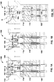
- a distance that the valve stems travels between the open and closed positions also referred to as a stroke length L , see FIG. 1A , is about 15 mm.
- the actuation plate When the injection cycle has finished, the actuation plate returns to the open position.
- the valve stems can move freely between the closed and open positions via actuation by the actuation plate.
- the threshold force holds the pistons against the actuation plate and allows the actuation plate to pull the valve stems out of the gates. That is, the threshold force is greater than any holding force(s) exerted on the valve stems at the gate (e.g., a force generated by cooled melt in the mold or by another obstruction tending to prevent the valve stem from moving out of the gate).
- one or more of the valve stems becomes stuck in the closed position (e.g., stuck at the gate), as illustrated in FIG. 1C .
- the threshold force applied to the air piston i.e., the pressurized air applied to the underside of the air piston
- the threshold force is no longer sufficient to hold the piston against the actuation plate/retainer plate and pull the valve stem out of the gate. That is, the threshold force is less than the holding force exerted on the valve stem at the gate.
- the corresponding stuck piston becomes separated from the portion of the actuation plate (e.g., from the retainer plate) as the actuation plate moves towards the opened position.
- separation from the portion of the actuation plate may mean that pressurized air A no longer presses the piston against the portion of the actuation plate (e.g., the retainer plate). That is, the stuck piston no longer moves with movement of the actuation plate (e.g., the stuck piston does not reciprocate between the open and closed position). Instead, the actuation plate moves relative to the corresponding stuck valve stem and associated piston.
- the stuck piston may still remain within the actuation plate (e.g., within a piston bore in the actuation plate).
- valve stems may be stuck at the gate (e.g., when one or more of the mold cavities is down), the hot runner may still continue to move the unstuck pistons and valve stems between the open and closed positions. In such a situation, the threshold force applied to the unstuck valve stems by the pressurized air is still sufficient to hold the unstuck valve stems to the portion of the actuation plate during plate actuation.
- the stuck valve stems and associated air pistons are maintained in the stationary position relative to the reciprocating actuation plate.
- the actuation plate may include piston bores that receive the air pistons. As the actuation plate reciprocates, the air piston remains stationary, being held by the stuck valve stem, within the piston bore.
- the pressurized air beneath the air piston is simply compressed.
- the system when one or more cavities are down (i.e., when one or more valve stems are stuck in the closed position), the system also may be stopped to allow for repairs. In such a situation, once the machine and pressurized air supply are turned off, the pistons may be separated from the actuation plate and may be removed for repair.
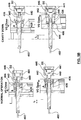
- FIGS. 1A-1C illustrate an example of a hot runner 100 according to one aspect.
- both valve stems 102 are pressed against the portion of the actuation plate via pressurized air A .
- the valve stems 102 are coupled to pistons 106, and pressurized air A holds (biases) the pistons upwardly (see the arrow labeled U ) against a retainer plate 107 at the back of the actuation plate 104.
- the pressurized air A travels through air channels 108 in an air supply circuit formed in the actuation plate 104.
- the hot runner 100 also includes, amongst other things, a manifold 110 for passing melt from a sprue bushing (not shown) to the nozzles (not shown), a manifold-backing plate 112, and a backing plate 114.
- FIG. 1B shows the actuation plate 104 in the closed position, after the actuation plate 104 has traveled a stroke length L (see FIG. 1A ) and the valve stems close the gate 105 (nozzle not shown). As with FIG. 1A , both valve stems are still pressed against the retainer plate 107 via pressurized air A acting on the pistons.
- FIG. 1C illustrates the actuation plate 104 again in the open position, however, in this embodiment, one of the valve stems 102s is stuck at the gate 105.
- the holding force applied to the valve stem at the gate is greater than the threshold force pressing the valve stem 102s/piston106s upwardly against the retainer plate 107.
- the corresponding stuck air piston 106s is connected to the stuck valve stem 102s and is no longer pressed against the retainer plate 107 (see e.g., the space O between the piston 106s and the retainer plate 107) and does not move with the movement of the actuation plate 104.
- the unstuck valve stem 102 is still pressed against the retainer plate 107 via its corresponding piston 106 and has travelled with the actuation plate 104 to the open position.
- the hot runner may include one or more valve stems 102.
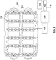
- the actuation plate 104 may be arranged to receive 48 valve stems and corresponding pistons. That is, the actuation plate 104 may have one or more drops 116 (e.g., 48 drops in FIG. 2 ), where the air pistons may be held against the actuation plate 104 (see FIG. 1 ).
- Other systems may include more or less drops, such as 24, 72, 96 or more.
- valve stem can move upward to open the gate.
- pressurized air may then be supplied to a top side of the piston.
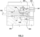
- the piston 206 may be held in contact with a retainer plate 207.
- a seal 209 is used to maintain the air pressure A in the cylinder/bore on the underside of the piston, as will be appreciated by those skilled in the art.
- the cylinder may be an air piston bore 226 formed in the actuation plate 204.
- the seal(s) 209 remains static, like an O-Ring seal, for example. In such embodiments, as the actuation plate moves, so do the air pistons 206, which are pressed against the actuation plate via pressurized air.
- the seal 209 acts as a sliding dynamic seal.
- the air supply circuit supplies pressurized air A to each piston 104 via air channels 108 in the actuation plate 104.
- all air channels are in fluid communication with each other and with a source of air pressure.
- the actuation plate 104 and air channels 108 are operatively connected to one or more pressure sensors 118 that detect a pressure in the circuit and/or at each of the drops.
- the pressure sensor(s) may provide feedback to a regulator 120, which may regulate a supply S of pressurized air into the circuit via a valve 122.
- the system will stop the molding process if the pressure sensor detects as loss of pressure during the molding process, that is below a specified set point. The sensor protects the hotrunner from over pressurization.
- the pistons (and valve stems) could lag behind the motion of the actuation plate, and injection could occur with valve stems in closed or partially open position.
- the pressure sensor prevents system from injecting at start up, if air supply connection is not completed between machine and hotrunner.
- the valve 122 is adjusted such that a threshold pressure may be maintained at each drop.
- the actuation plate 100 is also operatively connected to a user interface 124, which includes software and controls (not shown) that enable the operator to activate cavity down and cavity down maintenance functions.
- cavity down may mean that the valve stem is stuck at the gate such that the cavity 109 may not be used for further injection molding.
- the air channels 108 are formed by gun drilling bores or holes through the actuation plate along the desired paths and plugging the ends of the bores or holes with a plug.
- the actuation plate also may be manufactured according to other processes to create the necessary channels.
- the actuation plate may be formed by a split-and-bonded two-piece actuation plate (e.g., welding, brazing or diffusion bonding a two-piece actuation plate).
- the actuation plate also may be formed using solid free form fabrication, also known as additive manufacturing fabrication.
- the hot runner may be configured to operate when a cavity 109 ( FIG. 1C ) is down (e.g., when the valve stem is stuck in the gate leading to the cavity). As will be described in more detail below, this may be accomplished by maintaining the position of the stuck piston when the corresponding valve stem is stuck at the gate as the plate moves. For example, the piston may remain within the actuation plate in the stuck position. In such embodiments, the actuation plate may continue to reciprocate without being held back by the stuck valve stem(s) and/or by the corresponding stuck piston(s).
- the actuating plate may include a piston bore 226 that receives the air piston 206.
- the size and shape of the piston bore 226 corresponds to the size and shape of the air piston 206.
- a diameter of the piston bore may correspond to an outer diameter of the air piston 206 and be sized to accommodate the seal.
- the piston and piston bore may both be cylindrically shaped, although other suitable shapes may be used.
- the air piston 206 is disposed within the piston bore 226 and is pressed against the retainer plate 207 via pressurized air A .
- the seal 209 maintains the air pressure in the piston bore 226 on the underside of the piston.
- the pressurized air A is on and generates the threshold force that exceeds the holding force, the air piston 206 may travel back and forth with the reciprocating movement of the actuating plate 204.
- the pressurized air A is turned off, the piston will no longer remain against the retainer plate 207 and the valve stem 202 will not reciprocate with movement of the actuation plate.
- the corresponding stuck piston effectively separates from the actuation plate, allowing the actuation plate to move and further compressing the air beneath the piston.
- the position of the stuck air piston is illustrated by the dashed line labeled P .
- the stuck piston is no longer pressed against the retainer plate 207, however, the stuck piston still remain within the piston bore 226.
- the piston bore 226 is sized to accommodate the stuck and unstuck position of the air pistons 206.
- the length of the bore LB is greater than a stroke length L to accommodate the stuck position P of the air piston 206.
- the reciprocating actuation plate moves relative to the stuck air piston. That is, the piston bore 226 moves freely around the stuck air piston 206 when the actuation plate reciprocates back and forth. As a result, the hot runner may continue to operate without having to physically disconnect the piston from the actuation plate.
- the hot runner may be configured to protect the valve stems by limiting the force that is applied to the valve stems.
- the valve stem may be protected when the valve stem encounters an obstruction (e.g., a foreign body in the drop), that would otherwise overpower the force acting on the piston.
- an obstruction e.g., a foreign body in the drop
- Examples of hot runners 100 with a valve stem protection mechanism can be found in FIGS. 4 and 5A-5C .
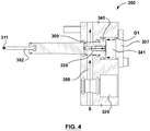
- the hot runner 300 may include a piston 340 with an air passageway 330 through which a supply of pressurized air S may pass into a chamber 341, between the piston and the retainer plate 307 (e.g., the pressurized air is passed from the air channel 308).
- the chamber may be the air piston bore.
- the pressurized air biases the valve stems towards the closed position (e.g., towards the gate). That is, with reference to FIG. 4 , air pressure D1 may be used to push the piston/valve stem toward the closed position.
- air pressure D1 may be used to push the piston/valve stem toward the closed position.
- the system provides for the plate actuation to remain operative in the event the valve stem becomes stuck and/or encounters an obstruction.
- the hot runner 400 may include a first piston 406 for valve stem actuation, as described above, that allows for continued plate actuation even when a valve stem become stuck at the gate.
- the hot runner also may include a second piston 440 for valve stem protection, allowing for continued plate actuation even when the valve stem encounters an obstruction.
- the first piston 406 may include an air piston 406 for holding the valve stem 402 against the retainer 407 via pressurized air A acting on the piston 406 as the actuation plate 404 reciprocates back and forth to drive the valve stem 402. This first piston arrangement operates in a manner described above with respect to FIGS. 1-3 .
- the second piston 440 may be arranged similar to that of FIG. 4 .
- the second piston 440 may be coupled to the air piston 406 and may extend through the retainer plate 404. More specifically, the second piston 440 may include a shaft portion 442 that extends through the first air piston and is directly coupled to the valve stem 402.
- the first piston 406 also includes a shaft portion 444surrounding the shaft 442 of the second piston 440 and extending through the actuation plate 404.
- the first piston 406 also includes a housing 446 formed on the piston and extending in a direction opposite the valve stem. This housing acts as the cylinder bore (e.g., see chamber 441) for the second piston 440.
- This second piston acts as a protection system to prevent damage to the valve stem if an obstruction 411 is preventing the valve stem from moving toward the closed position
- the air piston 406 and the protecting piston 440 of FIG. 5A include air passageways 430 through which pressurized air passes from the air channels 408 into a chamber 441.
- pressurized air A acts on the first piston, holding the first piston 406 against the retainer 407
- pressurized air D2 acts on the second piston 440, biasing the second piston 440 towards the closed position.
- the retainer pushes on the first piston 406 and the air pressure D2 acts on the second piston 440.
- the air acting on the air piston 406 e.g., the air in the piston bore 426 is allowed to simply compress, as shown in FIG. 5B , as the actuation plate 406 moves to the open position.
- the actuation plate 404 moves to the open position while the first piston 406, housing and valve stem 402 remains stationary.
- the actuation plate will still continue to push on the retainer 407, which in turn pushes the piston 406 and valve stem 402.
- the first piston 406 is configured to pull on the housing when the actuation plate moves towards the closed position, which will compress the air acting on the second piston (e.g., the air in the chamber 441).
- the second piston e.g., the air in the chamber 441.
- the hot runner 500 may include a spring 550 to provide valve stem 502 protection.
- the spring 550 may be used to protect the valve stem during the purging process of a multi-material hot runner when an unmelt of molding material blocks the gate.
- a secondary (e.g., barrier) molding material in barrier channels of the nozzles using a reverse flow of primary (e.g., skin) molding material (e.g., from the inner and/or outer flow channels of the nozzle).
- the valve stems are retracted into a back position, a short shot (e.g., a partial shot) of the primary molding material is injected through the nozzle into the molding cavity, and the melt is allowed to solidify.
- the solidified melt forms a short (e.g., partially) molded article that plugs the gate.
- the plug redirects the flow into the secondary (e.g., barrier) channels of the nozzle to complete the purge.
- the solidified plugs must be removed from the respective gates.
- valve stems may be subjected to an abnormal (e.g., high) closing force that may shear the safety pins that couples the valve stems to the air pistons.
- an abnormal closing force e.g., high
- the spring 550 may be used to protect the valve stem in other applications such as, for example, a monolayer PET systems (i.e. the molding of preforms of the type for blow molding into containers that are molded entirely of PET material without layers).
- a monolayer PET systems i.e. the molding of preforms of the type for blow molding into containers that are molded entirely of PET material without layers.
- melt drool is able to solidify to produce a localized 'gate nub' (i.e. partial molding in the region of the gate channel).
- the technician manually removes these gate nubs to allow plastic to fill the cavity as the solidified nubs cannot be ejected or re-melted by the next shot.
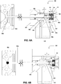
- valve stem 502 is coupled to the air piston 506, which, in turn, is held in contact with the retainer plate 507 via pressurized air A travelling through the air channels 508.
- the air piston 506 is received in and moves relative to the air piston bore 526 formed in the actuation plate 504.
- a seal 509 may be used to maintain the air pressure A in piston bore 526.
- the air piston 506 includes a housing 546 that includes a bore (see, e.g., cylinder 541) in which the spring 550 is housed.
- the spring 550 is coupled to the proximal end of the valve stem 502 via a valve stem assembly 553 (see also the exploded perspective view of FIG. 7 ).
- the valve stem assembly 553 may include a valve stem head 554 that is received in a sleeve 556 of a valve stem retainer 558.
- the valve stem assembly also includes a shear pin 560 that connects the valve stem head 554 to the spring 552.
- the shear pin 560 may be removably attached to the valve stem head 554 in some embodiment, although it also may be permanently attached.
- the valve stem assembly also may be housed in the cylinder 541 of the air piston 506. As shown in FIG. 6A , a spring cap 551 is screwed into the housing to close the cylinder, holding the spring 550 therein.
- the spring 552 in a normal operating position, the spring 552 is held in between the valve stem retainer and the spring cap 552, and travels back and forth during plate actuation. As will be appreciated, in such a normal operating position, the spring may be preloaded to a specific force to ensure that pressure cannot force the valve stem backwards and create a tall gate. In some embodiments, the spring 552 biases the valve stem towards the piston. In some embodiments, a gap G is maintained between the valve stem retainer 558 and the air piton 506, which allows the valve stem 502 to float within the air piston 506. In some embodiments, the gap is between about 0.01 and 0.5 mm.
- FIG. 6B illustrates an embodiment in which the valve stem 502 encounters an obstruction 562 that stops valve stem 502 movement.
- the actuation plate 504 has continued to move towards the gate, which, in turn, pushes the piston 506 and valve stem 502.
- the spring 550 may be compressed as the actuation plate 504 moves towards the closed position. Without wishing to be bound by theory, compressing the spring may limit the force exerted on the valve stem via the obstruction.
- compressing the spring allows the valve stem to remain stationary with respect to the actuation plate 404.
- the gap G increases as the spring compresses.
- the air pressure A is still sufficient to keep the piston 506 pressed against the retainer plate 507.
- the hot runner may be configured to maintain and/or to extend the life of the seals used.
- the actuation plate may be cycled prior to starting up in a maintenance mode, with all nozzles tip heaters off. All valve stems and pistons may then be locked in the closed positions by the solidified drops. The machine may then turn off the air supply to the actuation plate and vent to the atmosphere. The actuation plate may then cycle back and forth to work the seals in the air piston. After this maintenance, the machine may resume normal system operation.
- the hot runner may be configured to shut down if the machine senses a drop in pressure. For example, if a loss of pressure is detected (e.g., the pressurized air supply S is decreased), the machine may sound an alarm and stop the molding cycle. As will be appreciated, the molding machine may be stopped to ensure that the machine does not inject with all or some of the valve stems in the closed position or if they lag behind, or if the gates are not fully open. In some embodiments, this pressure monitoring may mitigate the risk of injecting on closed valve stems and over pressurizing (e.g., an internal leak) the hot runner.
- a loss of pressure e.g., the pressurized air supply S is decreased
- the molding machine may be stopped to ensure that the machine does not inject with all or some of the valve stems in the closed position or if they lag behind, or if the gates are not fully open.
- this pressure monitoring may mitigate the risk of injecting on closed valve stems and over pressurizing (e.g., an internal leak) the
- valve stem being held against the actuation plate via air pistons, (that is, the air pistons are held against the actuation plate via air pressure)
- the head of the valve stem itself may be pressed against the retainer plate. That is, a valve pin head 303 of the valve pin may be held against the actuation plate via air pressure and disposed within a bore via suitable seals.
Landscapes
- Engineering & Computer Science (AREA)
- Manufacturing & Machinery (AREA)
- Mechanical Engineering (AREA)
- Moulds For Moulding Plastics Or The Like (AREA)
- Injection Moulding Of Plastics Or The Like (AREA)
Claims (15)
- Heißkanal (100, 200, 300, 400) einer Spritzgießmaschine zum Führen von Schmelze in einen Formhohlraum, wobei der Heißkanal umfasst:eine erste ventilgesteuerte Düse mit einem ersten Ventilschaft (102, 202, 302, 402);einen ersten Kolben (106, 206, 306, 406), der mit dem ersten Ventilschaft gekoppelt ist;eine zweite ventilgesteuerte Düse mit einem zweiten Ventilschaft (102, 202, 302, 402) und einem zweiten Kolben (106, 206, 306, 406), der mit dem zweiten Ventilschaft gekoppelt ist; undeine Betätigungsplatte (104, 204, 304, 404), die auf den ersten Kolben und den zweiten Kolben wirkt, wobei die Betätigungsplatte dazu ausgestaltet ist, den ersten Ventilschaft und den zweiten Ventilschaft zwischen einer offenen Stellung und einer geschlossenen Stellung zu bewegen;dadurch gekennzeichnet, dass der erste Kolben und der zweite Kolben innerhalb der Betätigungsplatte durch Druckluft (A) so vorgespannt sind, dass sie sich während des normalen Betriebs mit der Bewegung der Betätigungsplatte bewegen.
- Heißkanal (100, 200, 300, 400) nach Anspruch 1, wobei die Druckluft den Ventilschaft zu einer offenen Stellung hin vorspannt.
- Heißkanal (100, 200, 300, 400) nach Anspruch 1, wobei die Betätigungsplatte (104, 204, 304, 404) Kolbenbohrungen (226) definiert, die so angeordnet sind, dass sie den ersten und zweiten Kolben (106, 206, 306, 406) aufnehmen.
- Heißkanal (100, 200, 300, 400) nach Anspruch 3, wobei die Betätigungsplatte Halteplatten (107, 207, 307, 407) beinhaltet, und wenn der erste und zweite Kolben (106, 206, 306, 406) in den Kolbenbohrungen (226) angeordnet und zu der offenen Stellung hin vorgespannt sind, der erste und zweite Kolben während des normalen Betriebs gegen die Halteplatten (107, 207, 307, 407) gedrückt werden.
- Heißkanal nach Anspruch 1, wobei die Betätigungsplatte ferner einen oder mehrere Luftkanäle (108, 308, 408) zum Zuführen von Druckluft (A) an den ersten und zweiten Kolben (106, 206, 306, 406) umfasst.
- Heißkanal (100, 200, 300, 400) nach Anspruch 1, wobei, wenn der erste Ventilschaft (102, 202, 302, 402) in der geschlossenen Stellung stecken bleibt, der erste Kolben (106, 206, 306, 406) feststehend bleibt, während sich die Betätigungsplatte (104, 204, 304, 404) weiter bewegt; und
wobei der zweite Ventilschaft (102, 202, 302, 402) und der zugehörige Kolben mittels Druckluft (A) gegen den Abschnitt der Betätigungsplatte gehalten werden und sich mit der Betätigungsplatte bewegen. - Heißkanal (100, 200, 300, 400) nach Anspruch 1, wobei die Druckluft den Ventilschaft zu einer geschlossenen Stellung hin vorspannt.
- Heißkanal (100, 200, 300, 400) nach Anspruch 1, wobei:der erste Kolben einen Durchgang (330, 430) beinhaltet, der angeordnet ist, um Druckluft an eine Kammer (341, 441) zu übertragen, wobei die Druckluft den Ventilschaft in eine geschlossene Stellung vorspannt;wobei, wenn der erste Ventilschaft auf ein Hindernis (311, 411) stößt, während er zu einer geschlossenen Stellung hin bewegt wird, die Druckluft, die auf den ersten Kolben wirkt, in der Kammer komprimiert wird.
- Heißkanal (100, 200, 300, 400) nach Anspruch 8, wobei die Kammer (341) in der Betätigungsplatte (104, 204, 304, 404) ausgebildet ist.
- Heißkanal (100, 200, 300, 400) nach Anspruch 8, wobei der erste Kolben (340, 440) in der Kammer (341, 441) angeordnet ist.
- Heißkanal (100, 200, 300, 400) nach Anspruch 8, ferner umfassend einen weiteren Kolben (104, 206, 306, 406), der mit dem Ventilschaft (102, 202, 302, 402) und dem ersten Kolben (341, 441) gekoppelt ist, wobei der weitere Kolben mittels Druckluft gegen einen Abschnitt der Betätigungsplatte gehalten wird, um sich mit der Bewegung der Betätigungsplatte (104, 204, 304, 404) zu bewegen.
- Heißkanal nach Anspruch 11, wobei der weitere Kolben einen Luftdurchgang umfasst, der angeordnet ist, um Druckluft an die Kammer zu übertragen.
- Heißkanal nach Anspruch 11, wobei die Betätigungsplatte eine Kolbenbohrung (226) umfasst, die angeordnet ist, um den weiteren Kolben (106, 206, 306, 406) aufzunehmen.
- Heißkanal nach Anspruch 12, wobei der weitere Kolben ein Gehäuse umfasst, das sich in einer dem Ventilschaft (102, 202, 302, 402) entgegengesetzten Richtung erstreckt, wobei die Kammer durch das Gehäuse definiert wird.
- Heißkanal nach Anspruch 1, ferner umfassend eine Feder (550), die den Ventilschaft (560) zu dem ersten Kolben (506) hin vorspannt.
Applications Claiming Priority (3)
| Application Number | Priority Date | Filing Date | Title |
|---|---|---|---|
| US201562258704P | 2015-11-23 | 2015-11-23 | |
| US201662290252P | 2016-02-02 | 2016-02-02 | |
| PCT/CA2016/051317 WO2017088044A1 (en) | 2015-11-23 | 2016-11-14 | Valve stem actuation |
Publications (3)
| Publication Number | Publication Date |
|---|---|
| EP3380296A1 EP3380296A1 (de) | 2018-10-03 |
| EP3380296A4 EP3380296A4 (de) | 2019-07-17 |
| EP3380296B1 true EP3380296B1 (de) | 2020-03-18 |
Family
ID=58762798
Family Applications (1)
| Application Number | Title | Priority Date | Filing Date |
|---|---|---|---|
| EP16867474.5A Active EP3380296B1 (de) | 2015-11-23 | 2016-11-14 | Ventilschaftbetätigung |
Country Status (6)
| Country | Link |
|---|---|
| US (2) | US10882233B2 (de) |
| EP (1) | EP3380296B1 (de) |
| JP (2) | JP6791978B2 (de) |
| CN (1) | CN108367474B (de) |
| CA (1) | CA3004591C (de) |
| WO (1) | WO2017088044A1 (de) |
Families Citing this family (2)
| Publication number | Priority date | Publication date | Assignee | Title |
|---|---|---|---|---|
| JP6791978B2 (ja) | 2015-11-23 | 2020-11-25 | ハスキー インジェクション モールディング システムズ リミテッドHusky Injection Molding Systems Limited | バルブステムの作動 |
| PL3991941T3 (pl) * | 2020-10-27 | 2024-03-11 | Mold-Masters (2007) Limited | Urządzenie do formowania wtryskowego z płytą trzpienia zaworu |
Family Cites Families (67)
| Publication number | Priority date | Publication date | Assignee | Title |
|---|---|---|---|---|
| US3892512A (en) | 1973-09-13 | 1975-07-01 | Alan V Diehl | Transfer molding apparatus with resilient pad to distribute molding pressure |
| EP0021273B1 (de) | 1979-06-12 | 1984-09-12 | Hendrikus Jacobus Elisabeth Schouenberg | Spritzgussmechanismus zum Giessen von Kunststoffen |
| US4443178A (en) | 1981-07-30 | 1984-04-17 | Toshiba Kikai Kabushiki Kaisha | Valve nozzle devices |
| DE3245571C2 (de) | 1982-12-09 | 1985-04-11 | Männer, Otto, 7836 Bahlingen | Nadelverschluß-Düse für Spritzgießformen |
| US5078589A (en) | 1990-06-15 | 1992-01-07 | Osuna Diaz J M | Multicavity injection molding apparatus having precision adjustment and shut off of injection flow to individual mold cavities |
| JPH05507445A (ja) | 1991-02-12 | 1993-10-28 | 世紀株式会社 | 改良ホットランナ金型構成体とその使用 |
| DE4206319C2 (de) | 1992-02-29 | 1994-04-28 | Otto Maenner | Nadelverschlußdüse mit Kolbenantrieb |
| JP2612795B2 (ja) * | 1992-06-15 | 1997-05-21 | 世紀株式会社 | ランナーレス射出成形装置 |
| US5374182A (en) * | 1992-09-30 | 1994-12-20 | Husky Injection Molding Systems Ltd. | Hot runner manifold bushing |
| DE4324275C2 (de) | 1993-07-20 | 1996-05-02 | Incoe Corp | Pneumatische Steuervorrichtung für Heißkanalnadelventile für Spritzgießwerkzeuge |
| CA2111248C (en) * | 1993-12-13 | 2002-05-07 | Alex C. Teng | Valve gated injection molding apparatus with a spring in the piston |
| JP3022433U (ja) * | 1995-09-06 | 1996-03-26 | 世紀株式会社 | 射出成形型用バルブゲート装置 |
| DE19611880A1 (de) | 1996-03-26 | 1997-10-02 | Zahoransky Formenbau Gmbh | Spritzgießwerkzeug |
| US6361300B1 (en) | 1998-04-21 | 2002-03-26 | Synventive Molding Solutions, Inc. | Manifold system having flow control |
| US6062840A (en) * | 1997-09-02 | 2000-05-16 | Dynisco Hotrunners, Inc. | Hot runner system for coinjection molding |
| CA2261367C (en) | 1999-02-08 | 2008-04-22 | Mold-Masters Limited | Injection molding valve member actuating mechanism |
| DE19943797B4 (de) | 1999-09-13 | 2009-07-30 | Yudo Co., Ltd. | Kunststoffeinspritzvorrichtung für Spritzgussmaschinen mit einem Ventilsystem, das Einzelkolben-betätigte Mehrfach-Ventilstifte aufweist |
| US6343925B1 (en) * | 2000-04-14 | 2002-02-05 | Husky Injection Molding Systems, Ltd. | Hot runner valve gate piston assembly |
| US6755641B1 (en) | 2000-09-01 | 2004-06-29 | Mold-Masters Limited | Stack injection molding apparatus with separately actuated arrays of valve gates |
| FR2829058B1 (fr) | 2001-09-06 | 2005-05-13 | Delachaux Sa | Procede et dispositif d'injection d'une matiere thermoplastique dans une empreinte d'un moule |
| CA2371346A1 (en) | 2002-02-11 | 2003-08-11 | Gino Colonico | Valve pin locking mechanism |
| US7014455B2 (en) * | 2002-03-14 | 2006-03-21 | Mold-Masters Limited | Valve-gated injection molding system with side-mounted actuator |
| US7131834B2 (en) * | 2002-08-14 | 2006-11-07 | Mold-Masters Ltd. | Valve pin adjustment device |
| DE60328425D1 (de) | 2002-12-03 | 2009-08-27 | Mold Masters 2007 Ltd | Heißkanal-Koinjektionsdüse |
| US7168943B2 (en) | 2003-08-29 | 2007-01-30 | Mold-Masters Limited | Guided valve pin for an injection molding apparatus |
| US7125246B2 (en) | 2003-10-08 | 2006-10-24 | Mold Hotrunner Solutions Inc. | Hot runner for molding small plastic articles |
| KR100529839B1 (ko) * | 2003-12-09 | 2005-11-23 | 김혁중 | 사출성형기용 리니어 밸브 게이트장치 |
| US7210922B1 (en) * | 2004-11-18 | 2007-05-01 | Tech Mold, Inc. | Valve pin operating mechanism |
| US7341688B2 (en) | 2004-11-19 | 2008-03-11 | Husky Injection Molding Systems Ltd. | Valve gate for a hot runner injection molding machine |
| DE102005017413B4 (de) * | 2005-04-15 | 2008-06-26 | Otto Männer Innovation GmbH | Spritzgießdüse mit zwei Austrittsöffnungen |
| KR200404991Y1 (ko) * | 2005-10-22 | 2006-01-10 | 김혁중 | 사출성형기용 밸브장치 |
| KR100655750B1 (ko) | 2005-11-16 | 2006-12-13 | 김혁중 | 다캐비티 금형용 사출성형기 밸브장치 |
| DE202005020412U1 (de) | 2005-12-28 | 2007-05-10 | Günther Heisskanaltechnik Gmbh | Betätigungsvorrichtung für Verschlußnadeln in Spritzgießvorrichtungen mit Nadelverschlußdüsen |
| DE202006000036U1 (de) | 2006-01-02 | 2007-05-16 | Günther Heisskanaltechnik Gmbh | Betätigungsvorrichtung für Verschlußnadeln in Spritzgießvorrichtungen mit Nadelverschlußdüsen |
| TW200732128A (en) | 2006-01-10 | 2007-09-01 | Guenther Heisskanaltechnik | Actuating device for shut-off needles in injection moulding devices comprising needle shut-off nozzles |
| CA2592237A1 (en) | 2006-06-19 | 2007-12-19 | Murray Feick | Valve pin actuating device for a hot runner apparatus |
| ITRM20060499A1 (it) * | 2006-09-20 | 2008-03-21 | Sipa Societa Industrializzazione E Progettazione | Asta di otturazione |
| US7527490B2 (en) | 2006-10-13 | 2009-05-05 | Mold-Masters (2007) Limited | Coinjection molding apparatus and related hot-runner nozzle |
| US7766646B2 (en) | 2007-06-22 | 2010-08-03 | Mold-Masters (2007) Limited | Injection molding apparatus with plate actuation of valve pins |
| US7722351B2 (en) | 2007-10-22 | 2010-05-25 | Mold-Masters (2007) Limited | Injection molding apparatus having magnetic valve pin coupling |
| US8220362B2 (en) | 2007-10-23 | 2012-07-17 | Husky Injection Molding Systems Ltd. | Cam apparatus for valve stem actuation |
| JP2009160844A (ja) | 2008-01-08 | 2009-07-23 | Mold-Masters (2007) Ltd | 同時射出成形装置及びこれに関連するホットランナノズル |
| CA2718133C (en) | 2008-03-24 | 2014-06-03 | Husky Injection Molding Systems Ltd. | Safety connector for hot runner, having latch destructively interlocking valve stem with actuation plate |
| WO2010015074A1 (en) | 2008-08-04 | 2010-02-11 | Mold-Masters (2007) Limited | Breakable mechanical connection between injection molding valve pin plate and valve pins |
| US7988445B2 (en) | 2008-08-21 | 2011-08-02 | Mold-Masters (2077) Limited | Injection molding apparatus having a nozzle tip component for taking a nozzle out-of-service |
| DE102009048796B4 (de) | 2008-10-10 | 2018-10-25 | Mold-Masters (2007) Limited | Spritzgießvorrichtung mit einer magnetischen Ventilnadelkupplung |
| US7963762B2 (en) * | 2008-11-18 | 2011-06-21 | Mold-Masters (2007) Limited | Injection molding apparatus having a valve pin coupling |
| EP2421689A4 (de) | 2009-04-21 | 2013-01-09 | Husky Injection Molding | Heisslaufsystem mit abhängig von einem elektromagnetischen aktuator beweglichem ventilschaft |
| US8100689B2 (en) | 2009-10-09 | 2012-01-24 | Husky Injection Molding Systems Ltd. | Safety connector for hot runner, having latch releasably interlocking valve stem with actuation plate |
| JP5514585B2 (ja) * | 2010-03-04 | 2014-06-04 | 世紀株式会社 | 射出成形機におけるバルブゲート開閉用バルブピンの押切力制限機構付きピストン装置 |
| CN201863357U (zh) | 2010-11-17 | 2011-06-15 | 柳道万和(苏州)热流道系统有限公司 | 热流道系统 |
| US8308476B2 (en) | 2011-03-01 | 2012-11-13 | Mold-Masters (2007) Limited | Injection molding apparatus having a magnetic valve pin coupling |
| US8591220B2 (en) * | 2011-03-04 | 2013-11-26 | Terry L. Schwenk | Valve pin and actuator assembly for injection molding |
| WO2012173955A1 (en) | 2011-06-15 | 2012-12-20 | Husky Injection Molding Systems Ltd | Molding system including stationary platen positioned between actuation assembly and stem-actuation plate |
| DE102011106606B4 (de) | 2011-06-16 | 2024-12-24 | Meusburger Georg GmbH & Co. KG | Vorrichtung zur gleichzeitigen Betätigung einer Vielzahl von Verschlussnadeln in einer Kunststoffspritzmaschine |
| WO2013074554A1 (en) | 2011-11-15 | 2013-05-23 | Husky Injection Modling Systems Ltd. | Reducing crown flash in injection-molding processes |
| WO2013074741A1 (en) | 2011-11-18 | 2013-05-23 | Husky Injection Molding Systems Ltd. | Mold-tool system including stem-compliance assembly |
| CN202367911U (zh) | 2011-12-21 | 2012-08-08 | 柳道万和(苏州)热流道系统有限公司 | 热流道系统之同步式阀针驱动装置 |
| JP5930741B2 (ja) * | 2012-02-01 | 2016-06-08 | 世紀株式会社 | 分割型バルブピン |
| DE102012003574A1 (de) | 2012-02-27 | 2013-05-02 | Otto Männer Innovation GmbH | Stelleinrichtung zum Verstellen der Nadelventile einer Heißkanal-Spritzgießvorrichtung |
| US8985997B2 (en) | 2012-03-02 | 2015-03-24 | Mold-Masters (2007) Limited | Valve bushing for an injection molding apparatus |
| JP5747849B2 (ja) * | 2012-03-26 | 2015-07-15 | 東レ株式会社 | ゲートバルブおよびゲートバルブの製造方法 |
| US9682507B2 (en) | 2012-05-31 | 2017-06-20 | Synventive Molding Solutions, Inc. | Injection molding flow control apparatus and method |
| JP2015523250A (ja) * | 2012-07-12 | 2015-08-13 | オットー メナー イノヴァツィオン ゲゼルシャフト ゲーエムベーハー | アクティブバルブピンによる係合解除を行う射出成形装置 |
| US8920155B2 (en) | 2013-03-15 | 2014-12-30 | Caco Pacific Corporation | Locking apparatus for common plate stem actuator |
| JP2017030155A (ja) * | 2015-07-29 | 2017-02-09 | 株式会社尾関ホットランナープラン | 射出成形装置 |
| JP6791978B2 (ja) * | 2015-11-23 | 2020-11-25 | ハスキー インジェクション モールディング システムズ リミテッドHusky Injection Molding Systems Limited | バルブステムの作動 |
-
2016
- 2016-11-14 JP JP2018545532A patent/JP6791978B2/ja active Active
- 2016-11-14 CN CN201680064914.1A patent/CN108367474B/zh active Active
- 2016-11-14 WO PCT/CA2016/051317 patent/WO2017088044A1/en not_active Ceased
- 2016-11-14 EP EP16867474.5A patent/EP3380296B1/de active Active
- 2016-11-14 US US15/773,824 patent/US10882233B2/en active Active
- 2016-11-14 CA CA3004591A patent/CA3004591C/en active Active
-
2020
- 2020-09-23 JP JP2020158504A patent/JP6983293B2/ja active Active
- 2020-11-17 US US17/099,858 patent/US11667066B2/en active Active
Non-Patent Citations (1)
| Title |
|---|
| None * |
Also Published As
| Publication number | Publication date |
|---|---|
| CA3004591C (en) | 2022-07-05 |
| CA3004591A1 (en) | 2017-06-01 |
| JP2020199779A (ja) | 2020-12-17 |
| US20210069953A1 (en) | 2021-03-11 |
| US10882233B2 (en) | 2021-01-05 |
| JP6983293B2 (ja) | 2021-12-17 |
| US11667066B2 (en) | 2023-06-06 |
| US20180326635A1 (en) | 2018-11-15 |
| EP3380296A4 (de) | 2019-07-17 |
| JP2019502577A (ja) | 2019-01-31 |
| CN108367474B (zh) | 2020-10-23 |
| JP6791978B2 (ja) | 2020-11-25 |
| WO2017088044A1 (en) | 2017-06-01 |
| EP3380296A1 (de) | 2018-10-03 |
| CN108367474A (zh) | 2018-08-03 |
Similar Documents
| Publication | Publication Date | Title |
|---|---|---|
| US7931455B2 (en) | Injection molding apparatus having magnetic valve pin coupling | |
| EP2214883B1 (de) | Verschlussdüseheisskanalsystem mit reduziertem ventilschafttropfen | |
| US7963762B2 (en) | Injection molding apparatus having a valve pin coupling | |
| EP0657270B1 (de) | Spritzgiessvorrichtung mit Verschlussdüse mit einer Feder im Kolben | |
| EP3092115B1 (de) | Ventilnadel und düsenanordnung sowie verfahren zur steuerung | |
| US11667066B2 (en) | Valve stem actuation | |
| EP2349673B1 (de) | Pneumatikventilvorrichtung zum ausstossen geformter kunststoffartikel aus einer form | |
| US20130251843A1 (en) | Valve gate system | |
| US9302416B1 (en) | Single nozzle valve gate | |
| CA2837637C (en) | Injection molding nozzle with dynamic seal | |
| US20090311364A1 (en) | Injection Molding Anti-Drool Nozzle | |
| US7678320B2 (en) | Anti-drool mechanism for a sprue bushing | |
| EP1560693B1 (de) | Ventilnadelüberkreuzungsdüse für etagenwerkzeug | |
| US6558148B1 (en) | Gas valve pin mechanism | |
| AU2002232474B2 (en) | Gas valve pin mechanism | |
| US20080093773A1 (en) | Reverse Motion Valve Gating System | |
| CN101072666A (zh) | 用于注射模塑的喷嘴和装置 | |
| AU2002232474A1 (en) | Gas valve pin mechanism |
Legal Events
| Date | Code | Title | Description |
|---|---|---|---|
| STAA | Information on the status of an ep patent application or granted ep patent |
Free format text: STATUS: THE INTERNATIONAL PUBLICATION HAS BEEN MADE |
|
| PUAI | Public reference made under article 153(3) epc to a published international application that has entered the european phase |
Free format text: ORIGINAL CODE: 0009012 |
|
| STAA | Information on the status of an ep patent application or granted ep patent |
Free format text: STATUS: REQUEST FOR EXAMINATION WAS MADE |
|
| 17P | Request for examination filed |
Effective date: 20180625 |
|
| AK | Designated contracting states |
Kind code of ref document: A1 Designated state(s): AL AT BE BG CH CY CZ DE DK EE ES FI FR GB GR HR HU IE IS IT LI LT LU LV MC MK MT NL NO PL PT RO RS SE SI SK SM TR |
|
| AX | Request for extension of the european patent |
Extension state: BA ME |
|
| DAV | Request for validation of the european patent (deleted) | ||
| DAX | Request for extension of the european patent (deleted) | ||
| A4 | Supplementary search report drawn up and despatched |
Effective date: 20190619 |
|
| RIC1 | Information provided on ipc code assigned before grant |
Ipc: B29C 45/84 20060101ALI20190613BHEP Ipc: B29C 45/28 20060101AFI20190613BHEP |
|
| REG | Reference to a national code |
Ref country code: DE Ref legal event code: R079 Ref document number: 602016032300 Country of ref document: DE Free format text: PREVIOUS MAIN CLASS: B29C0045200000 Ipc: B29C0045280000 |
|
| GRAP | Despatch of communication of intention to grant a patent |
Free format text: ORIGINAL CODE: EPIDOSNIGR1 |
|
| STAA | Information on the status of an ep patent application or granted ep patent |
Free format text: STATUS: GRANT OF PATENT IS INTENDED |
|
| RIC1 | Information provided on ipc code assigned before grant |
Ipc: B29C 45/28 20060101AFI20190918BHEP Ipc: B29C 45/84 20060101ALI20190918BHEP |
|
| INTG | Intention to grant announced |
Effective date: 20191007 |
|
| GRAS | Grant fee paid |
Free format text: ORIGINAL CODE: EPIDOSNIGR3 |
|
| GRAA | (expected) grant |
Free format text: ORIGINAL CODE: 0009210 |
|
| STAA | Information on the status of an ep patent application or granted ep patent |
Free format text: STATUS: THE PATENT HAS BEEN GRANTED |
|
| RAP1 | Party data changed (applicant data changed or rights of an application transferred) |
Owner name: HUSKY INJECTION MOLDING SYSTEMS LTD. |
|
| AK | Designated contracting states |
Kind code of ref document: B1 Designated state(s): AL AT BE BG CH CY CZ DE DK EE ES FI FR GB GR HR HU IE IS IT LI LT LU LV MC MK MT NL NO PL PT RO RS SE SI SK SM TR |
|
| REG | Reference to a national code |
Ref country code: GB Ref legal event code: FG4D |
|
| REG | Reference to a national code |
Ref country code: DE Ref legal event code: R096 Ref document number: 602016032300 Country of ref document: DE |
|
| REG | Reference to a national code |
Ref country code: AT Ref legal event code: REF Ref document number: 1245405 Country of ref document: AT Kind code of ref document: T Effective date: 20200415 Ref country code: IE Ref legal event code: FG4D |
|
| PG25 | Lapsed in a contracting state [announced via postgrant information from national office to epo] |
Ref country code: RS Free format text: LAPSE BECAUSE OF FAILURE TO SUBMIT A TRANSLATION OF THE DESCRIPTION OR TO PAY THE FEE WITHIN THE PRESCRIBED TIME-LIMIT Effective date: 20200318 Ref country code: FI Free format text: LAPSE BECAUSE OF FAILURE TO SUBMIT A TRANSLATION OF THE DESCRIPTION OR TO PAY THE FEE WITHIN THE PRESCRIBED TIME-LIMIT Effective date: 20200318 Ref country code: NO Free format text: LAPSE BECAUSE OF FAILURE TO SUBMIT A TRANSLATION OF THE DESCRIPTION OR TO PAY THE FEE WITHIN THE PRESCRIBED TIME-LIMIT Effective date: 20200618 |
|
| REG | Reference to a national code |
Ref country code: NL Ref legal event code: MP Effective date: 20200318 |
|
| PG25 | Lapsed in a contracting state [announced via postgrant information from national office to epo] |
Ref country code: HR Free format text: LAPSE BECAUSE OF FAILURE TO SUBMIT A TRANSLATION OF THE DESCRIPTION OR TO PAY THE FEE WITHIN THE PRESCRIBED TIME-LIMIT Effective date: 20200318 Ref country code: GR Free format text: LAPSE BECAUSE OF FAILURE TO SUBMIT A TRANSLATION OF THE DESCRIPTION OR TO PAY THE FEE WITHIN THE PRESCRIBED TIME-LIMIT Effective date: 20200619 Ref country code: BG Free format text: LAPSE BECAUSE OF FAILURE TO SUBMIT A TRANSLATION OF THE DESCRIPTION OR TO PAY THE FEE WITHIN THE PRESCRIBED TIME-LIMIT Effective date: 20200618 Ref country code: SE Free format text: LAPSE BECAUSE OF FAILURE TO SUBMIT A TRANSLATION OF THE DESCRIPTION OR TO PAY THE FEE WITHIN THE PRESCRIBED TIME-LIMIT Effective date: 20200318 Ref country code: LV Free format text: LAPSE BECAUSE OF FAILURE TO SUBMIT A TRANSLATION OF THE DESCRIPTION OR TO PAY THE FEE WITHIN THE PRESCRIBED TIME-LIMIT Effective date: 20200318 |
|
| REG | Reference to a national code |
Ref country code: LT Ref legal event code: MG4D |
|
| PG25 | Lapsed in a contracting state [announced via postgrant information from national office to epo] |
Ref country code: NL Free format text: LAPSE BECAUSE OF FAILURE TO SUBMIT A TRANSLATION OF THE DESCRIPTION OR TO PAY THE FEE WITHIN THE PRESCRIBED TIME-LIMIT Effective date: 20200318 |
|
| PG25 | Lapsed in a contracting state [announced via postgrant information from national office to epo] |
Ref country code: PT Free format text: LAPSE BECAUSE OF FAILURE TO SUBMIT A TRANSLATION OF THE DESCRIPTION OR TO PAY THE FEE WITHIN THE PRESCRIBED TIME-LIMIT Effective date: 20200812 Ref country code: LT Free format text: LAPSE BECAUSE OF FAILURE TO SUBMIT A TRANSLATION OF THE DESCRIPTION OR TO PAY THE FEE WITHIN THE PRESCRIBED TIME-LIMIT Effective date: 20200318 Ref country code: EE Free format text: LAPSE BECAUSE OF FAILURE TO SUBMIT A TRANSLATION OF THE DESCRIPTION OR TO PAY THE FEE WITHIN THE PRESCRIBED TIME-LIMIT Effective date: 20200318 Ref country code: SM Free format text: LAPSE BECAUSE OF FAILURE TO SUBMIT A TRANSLATION OF THE DESCRIPTION OR TO PAY THE FEE WITHIN THE PRESCRIBED TIME-LIMIT Effective date: 20200318 Ref country code: IS Free format text: LAPSE BECAUSE OF FAILURE TO SUBMIT A TRANSLATION OF THE DESCRIPTION OR TO PAY THE FEE WITHIN THE PRESCRIBED TIME-LIMIT Effective date: 20200718 Ref country code: RO Free format text: LAPSE BECAUSE OF FAILURE TO SUBMIT A TRANSLATION OF THE DESCRIPTION OR TO PAY THE FEE WITHIN THE PRESCRIBED TIME-LIMIT Effective date: 20200318 Ref country code: SK Free format text: LAPSE BECAUSE OF FAILURE TO SUBMIT A TRANSLATION OF THE DESCRIPTION OR TO PAY THE FEE WITHIN THE PRESCRIBED TIME-LIMIT Effective date: 20200318 Ref country code: CZ Free format text: LAPSE BECAUSE OF FAILURE TO SUBMIT A TRANSLATION OF THE DESCRIPTION OR TO PAY THE FEE WITHIN THE PRESCRIBED TIME-LIMIT Effective date: 20200318 |
|
| REG | Reference to a national code |
Ref country code: AT Ref legal event code: MK05 Ref document number: 1245405 Country of ref document: AT Kind code of ref document: T Effective date: 20200318 |
|
| REG | Reference to a national code |
Ref country code: DE Ref legal event code: R097 Ref document number: 602016032300 Country of ref document: DE |
|
| PLBE | No opposition filed within time limit |
Free format text: ORIGINAL CODE: 0009261 |
|
| STAA | Information on the status of an ep patent application or granted ep patent |
Free format text: STATUS: NO OPPOSITION FILED WITHIN TIME LIMIT |
|
| PG25 | Lapsed in a contracting state [announced via postgrant information from national office to epo] |
Ref country code: IT Free format text: LAPSE BECAUSE OF FAILURE TO SUBMIT A TRANSLATION OF THE DESCRIPTION OR TO PAY THE FEE WITHIN THE PRESCRIBED TIME-LIMIT Effective date: 20200318 Ref country code: DK Free format text: LAPSE BECAUSE OF FAILURE TO SUBMIT A TRANSLATION OF THE DESCRIPTION OR TO PAY THE FEE WITHIN THE PRESCRIBED TIME-LIMIT Effective date: 20200318 Ref country code: AT Free format text: LAPSE BECAUSE OF FAILURE TO SUBMIT A TRANSLATION OF THE DESCRIPTION OR TO PAY THE FEE WITHIN THE PRESCRIBED TIME-LIMIT Effective date: 20200318 Ref country code: ES Free format text: LAPSE BECAUSE OF FAILURE TO SUBMIT A TRANSLATION OF THE DESCRIPTION OR TO PAY THE FEE WITHIN THE PRESCRIBED TIME-LIMIT Effective date: 20200318 |
|
| 26N | No opposition filed |
Effective date: 20201221 |
|
| PG25 | Lapsed in a contracting state [announced via postgrant information from national office to epo] |
Ref country code: PL Free format text: LAPSE BECAUSE OF FAILURE TO SUBMIT A TRANSLATION OF THE DESCRIPTION OR TO PAY THE FEE WITHIN THE PRESCRIBED TIME-LIMIT Effective date: 20200318 |
|
| PG25 | Lapsed in a contracting state [announced via postgrant information from national office to epo] |
Ref country code: SI Free format text: LAPSE BECAUSE OF FAILURE TO SUBMIT A TRANSLATION OF THE DESCRIPTION OR TO PAY THE FEE WITHIN THE PRESCRIBED TIME-LIMIT Effective date: 20200318 |
|
| PG25 | Lapsed in a contracting state [announced via postgrant information from national office to epo] |
Ref country code: MC Free format text: LAPSE BECAUSE OF FAILURE TO SUBMIT A TRANSLATION OF THE DESCRIPTION OR TO PAY THE FEE WITHIN THE PRESCRIBED TIME-LIMIT Effective date: 20200318 |
|
| REG | Reference to a national code |
Ref country code: BE Ref legal event code: MM Effective date: 20201130 |
|
| PG25 | Lapsed in a contracting state [announced via postgrant information from national office to epo] |
Ref country code: IE Free format text: LAPSE BECAUSE OF NON-PAYMENT OF DUE FEES Effective date: 20201114 |
|
| PG25 | Lapsed in a contracting state [announced via postgrant information from national office to epo] |
Ref country code: TR Free format text: LAPSE BECAUSE OF FAILURE TO SUBMIT A TRANSLATION OF THE DESCRIPTION OR TO PAY THE FEE WITHIN THE PRESCRIBED TIME-LIMIT Effective date: 20200318 Ref country code: MT Free format text: LAPSE BECAUSE OF FAILURE TO SUBMIT A TRANSLATION OF THE DESCRIPTION OR TO PAY THE FEE WITHIN THE PRESCRIBED TIME-LIMIT Effective date: 20200318 Ref country code: CY Free format text: LAPSE BECAUSE OF FAILURE TO SUBMIT A TRANSLATION OF THE DESCRIPTION OR TO PAY THE FEE WITHIN THE PRESCRIBED TIME-LIMIT Effective date: 20200318 |
|
| PG25 | Lapsed in a contracting state [announced via postgrant information from national office to epo] |
Ref country code: MK Free format text: LAPSE BECAUSE OF FAILURE TO SUBMIT A TRANSLATION OF THE DESCRIPTION OR TO PAY THE FEE WITHIN THE PRESCRIBED TIME-LIMIT Effective date: 20200318 Ref country code: AL Free format text: LAPSE BECAUSE OF FAILURE TO SUBMIT A TRANSLATION OF THE DESCRIPTION OR TO PAY THE FEE WITHIN THE PRESCRIBED TIME-LIMIT Effective date: 20200318 |
|
| PG25 | Lapsed in a contracting state [announced via postgrant information from national office to epo] |
Ref country code: BE Free format text: LAPSE BECAUSE OF NON-PAYMENT OF DUE FEES Effective date: 20201130 |
|
| P01 | Opt-out of the competence of the unified patent court (upc) registered |
Effective date: 20230516 |
|
| PGFP | Annual fee paid to national office [announced via postgrant information from national office to epo] |
Ref country code: LU Payment date: 20251010 Year of fee payment: 10 |
|
| REG | Reference to a national code |
Ref country code: CH Ref legal event code: U11 Free format text: ST27 STATUS EVENT CODE: U-0-0-U10-U11 (AS PROVIDED BY THE NATIONAL OFFICE) Effective date: 20251201 |
|
| PGFP | Annual fee paid to national office [announced via postgrant information from national office to epo] |
Ref country code: DE Payment date: 20250912 Year of fee payment: 10 |
|
| PGFP | Annual fee paid to national office [announced via postgrant information from national office to epo] |
Ref country code: GB Payment date: 20251010 Year of fee payment: 10 |
|
| PGFP | Annual fee paid to national office [announced via postgrant information from national office to epo] |
Ref country code: FR Payment date: 20251010 Year of fee payment: 10 |
|
| PGFP | Annual fee paid to national office [announced via postgrant information from national office to epo] |
Ref country code: CH Payment date: 20251201 Year of fee payment: 10 |