EP3379324A1 - Bedrucktes dreidimensionales optisches bauteil mit eingebetteter funktionsfolie und entsprechendes herstellungsverfahren - Google Patents
Bedrucktes dreidimensionales optisches bauteil mit eingebetteter funktionsfolie und entsprechendes herstellungsverfahren Download PDFInfo
- Publication number
- EP3379324A1 EP3379324A1 EP18163712.5A EP18163712A EP3379324A1 EP 3379324 A1 EP3379324 A1 EP 3379324A1 EP 18163712 A EP18163712 A EP 18163712A EP 3379324 A1 EP3379324 A1 EP 3379324A1
- Authority
- EP
- European Patent Office
- Prior art keywords
- optical component
- dimensional optical
- printed
- foil
- component according
- Prior art date
- Legal status (The legal status is an assumption and is not a legal conclusion. Google has not performed a legal analysis and makes no representation as to the accuracy of the status listed.)
- Pending
Links
Images
Classifications
-
- B—PERFORMING OPERATIONS; TRANSPORTING
- B29—WORKING OF PLASTICS; WORKING OF SUBSTANCES IN A PLASTIC STATE IN GENERAL
- B29C—SHAPING OR JOINING OF PLASTICS; SHAPING OF MATERIAL IN A PLASTIC STATE, NOT OTHERWISE PROVIDED FOR; AFTER-TREATMENT OF THE SHAPED PRODUCTS, e.g. REPAIRING
- B29C64/00—Additive manufacturing, i.e. manufacturing of three-dimensional [3D] objects by additive deposition, additive agglomeration or additive layering, e.g. by 3D printing, stereolithography or selective laser sintering
- B29C64/10—Processes of additive manufacturing
- B29C64/106—Processes of additive manufacturing using only liquids or viscous materials, e.g. depositing a continuous bead of viscous material
- B29C64/112—Processes of additive manufacturing using only liquids or viscous materials, e.g. depositing a continuous bead of viscous material using individual droplets, e.g. from jetting heads
-
- B—PERFORMING OPERATIONS; TRANSPORTING
- B29—WORKING OF PLASTICS; WORKING OF SUBSTANCES IN A PLASTIC STATE IN GENERAL
- B29C—SHAPING OR JOINING OF PLASTICS; SHAPING OF MATERIAL IN A PLASTIC STATE, NOT OTHERWISE PROVIDED FOR; AFTER-TREATMENT OF THE SHAPED PRODUCTS, e.g. REPAIRING
- B29C35/00—Heating, cooling or curing, e.g. crosslinking or vulcanising; Apparatus therefor
- B29C35/02—Heating or curing, e.g. crosslinking or vulcanizing during moulding, e.g. in a mould
- B29C35/08—Heating or curing, e.g. crosslinking or vulcanizing during moulding, e.g. in a mould by wave energy or particle radiation
- B29C35/0805—Heating or curing, e.g. crosslinking or vulcanizing during moulding, e.g. in a mould by wave energy or particle radiation using electromagnetic radiation
-
- B—PERFORMING OPERATIONS; TRANSPORTING
- B29—WORKING OF PLASTICS; WORKING OF SUBSTANCES IN A PLASTIC STATE IN GENERAL
- B29C—SHAPING OR JOINING OF PLASTICS; SHAPING OF MATERIAL IN A PLASTIC STATE, NOT OTHERWISE PROVIDED FOR; AFTER-TREATMENT OF THE SHAPED PRODUCTS, e.g. REPAIRING
- B29C64/00—Additive manufacturing, i.e. manufacturing of three-dimensional [3D] objects by additive deposition, additive agglomeration or additive layering, e.g. by 3D printing, stereolithography or selective laser sintering
- B29C64/20—Apparatus for additive manufacturing; Details thereof or accessories therefor
- B29C64/205—Means for applying layers
- B29C64/223—Foils or films, e.g. for transferring layers of building material from one working station to another
-
- B—PERFORMING OPERATIONS; TRANSPORTING
- B29—WORKING OF PLASTICS; WORKING OF SUBSTANCES IN A PLASTIC STATE IN GENERAL
- B29C—SHAPING OR JOINING OF PLASTICS; SHAPING OF MATERIAL IN A PLASTIC STATE, NOT OTHERWISE PROVIDED FOR; AFTER-TREATMENT OF THE SHAPED PRODUCTS, e.g. REPAIRING
- B29C64/00—Additive manufacturing, i.e. manufacturing of three-dimensional [3D] objects by additive deposition, additive agglomeration or additive layering, e.g. by 3D printing, stereolithography or selective laser sintering
- B29C64/30—Auxiliary operations or equipment
- B29C64/386—Data acquisition or data processing for additive manufacturing
-
- B—PERFORMING OPERATIONS; TRANSPORTING
- B29—WORKING OF PLASTICS; WORKING OF SUBSTANCES IN A PLASTIC STATE IN GENERAL
- B29C—SHAPING OR JOINING OF PLASTICS; SHAPING OF MATERIAL IN A PLASTIC STATE, NOT OTHERWISE PROVIDED FOR; AFTER-TREATMENT OF THE SHAPED PRODUCTS, e.g. REPAIRING
- B29C64/00—Additive manufacturing, i.e. manufacturing of three-dimensional [3D] objects by additive deposition, additive agglomeration or additive layering, e.g. by 3D printing, stereolithography or selective laser sintering
- B29C64/40—Structures for supporting 3D objects during manufacture and intended to be sacrificed after completion thereof
-
- B—PERFORMING OPERATIONS; TRANSPORTING
- B29—WORKING OF PLASTICS; WORKING OF SUBSTANCES IN A PLASTIC STATE IN GENERAL
- B29D—PRODUCING PARTICULAR ARTICLES FROM PLASTICS OR FROM SUBSTANCES IN A PLASTIC STATE
- B29D11/00—Producing optical elements, e.g. lenses or prisms
- B29D11/00009—Production of simple or compound lenses
- B29D11/00432—Auxiliary operations, e.g. machines for filling the moulds
- B29D11/00442—Curing the lens material
-
- B—PERFORMING OPERATIONS; TRANSPORTING
- B29—WORKING OF PLASTICS; WORKING OF SUBSTANCES IN A PLASTIC STATE IN GENERAL
- B29D—PRODUCING PARTICULAR ARTICLES FROM PLASTICS OR FROM SUBSTANCES IN A PLASTIC STATE
- B29D11/00—Producing optical elements, e.g. lenses or prisms
- B29D11/0073—Optical laminates
-
- B—PERFORMING OPERATIONS; TRANSPORTING
- B29—WORKING OF PLASTICS; WORKING OF SUBSTANCES IN A PLASTIC STATE IN GENERAL
- B29D—PRODUCING PARTICULAR ARTICLES FROM PLASTICS OR FROM SUBSTANCES IN A PLASTIC STATE
- B29D11/00—Producing optical elements, e.g. lenses or prisms
- B29D11/0074—Production of other optical elements not provided for in B29D11/00009- B29D11/0073
- B29D11/00807—Producing lenses combined with electronics, e.g. chips
-
- B—PERFORMING OPERATIONS; TRANSPORTING
- B33—ADDITIVE MANUFACTURING TECHNOLOGY
- B33Y—ADDITIVE MANUFACTURING, i.e. MANUFACTURING OF THREE-DIMENSIONAL [3-D] OBJECTS BY ADDITIVE DEPOSITION, ADDITIVE AGGLOMERATION OR ADDITIVE LAYERING, e.g. BY 3-D PRINTING, STEREOLITHOGRAPHY OR SELECTIVE LASER SINTERING
- B33Y10/00—Processes of additive manufacturing
-
- B—PERFORMING OPERATIONS; TRANSPORTING
- B33—ADDITIVE MANUFACTURING TECHNOLOGY
- B33Y—ADDITIVE MANUFACTURING, i.e. MANUFACTURING OF THREE-DIMENSIONAL [3-D] OBJECTS BY ADDITIVE DEPOSITION, ADDITIVE AGGLOMERATION OR ADDITIVE LAYERING, e.g. BY 3-D PRINTING, STEREOLITHOGRAPHY OR SELECTIVE LASER SINTERING
- B33Y30/00—Apparatus for additive manufacturing; Details thereof or accessories therefor
-
- B—PERFORMING OPERATIONS; TRANSPORTING
- B33—ADDITIVE MANUFACTURING TECHNOLOGY
- B33Y—ADDITIVE MANUFACTURING, i.e. MANUFACTURING OF THREE-DIMENSIONAL [3-D] OBJECTS BY ADDITIVE DEPOSITION, ADDITIVE AGGLOMERATION OR ADDITIVE LAYERING, e.g. BY 3-D PRINTING, STEREOLITHOGRAPHY OR SELECTIVE LASER SINTERING
- B33Y50/00—Data acquisition or data processing for additive manufacturing
- B33Y50/02—Data acquisition or data processing for additive manufacturing for controlling or regulating additive manufacturing processes
-
- B—PERFORMING OPERATIONS; TRANSPORTING
- B33—ADDITIVE MANUFACTURING TECHNOLOGY
- B33Y—ADDITIVE MANUFACTURING, i.e. MANUFACTURING OF THREE-DIMENSIONAL [3-D] OBJECTS BY ADDITIVE DEPOSITION, ADDITIVE AGGLOMERATION OR ADDITIVE LAYERING, e.g. BY 3-D PRINTING, STEREOLITHOGRAPHY OR SELECTIVE LASER SINTERING
- B33Y80/00—Products made by additive manufacturing
-
- C—CHEMISTRY; METALLURGY
- C09—DYES; PAINTS; POLISHES; NATURAL RESINS; ADHESIVES; COMPOSITIONS NOT OTHERWISE PROVIDED FOR; APPLICATIONS OF MATERIALS NOT OTHERWISE PROVIDED FOR
- C09D—COATING COMPOSITIONS, e.g. PAINTS, VARNISHES OR LACQUERS; FILLING PASTES; CHEMICAL PAINT OR INK REMOVERS; INKS; CORRECTING FLUIDS; WOODSTAINS; PASTES OR SOLIDS FOR COLOURING OR PRINTING; USE OF MATERIALS THEREFOR
- C09D11/00—Inks
- C09D11/02—Printing inks
- C09D11/10—Printing inks based on artificial resins
- C09D11/101—Inks specially adapted for printing processes involving curing by wave energy or particle radiation, e.g. with UV-curing following the printing
-
- G—PHYSICS
- G02—OPTICS
- G02B—OPTICAL ELEMENTS, SYSTEMS OR APPARATUS
- G02B1/00—Optical elements characterised by the material of which they are made; Optical coatings for optical elements
- G02B1/04—Optical elements characterised by the material of which they are made; Optical coatings for optical elements made of organic materials, e.g. plastics
- G02B1/041—Lenses
-
- G—PHYSICS
- G02—OPTICS
- G02B—OPTICAL ELEMENTS, SYSTEMS OR APPARATUS
- G02B26/00—Optical devices or arrangements for the control of light using movable or deformable optical elements
- G02B26/02—Optical devices or arrangements for the control of light using movable or deformable optical elements for controlling the intensity of light
-
- G—PHYSICS
- G02—OPTICS
- G02C—SPECTACLES; SUNGLASSES OR GOGGLES INSOFAR AS THEY HAVE THE SAME FEATURES AS SPECTACLES; CONTACT LENSES
- G02C7/00—Optical parts
- G02C7/02—Lenses; Lens systems ; Methods of designing lenses
-
- G—PHYSICS
- G02—OPTICS
- G02C—SPECTACLES; SUNGLASSES OR GOGGLES INSOFAR AS THEY HAVE THE SAME FEATURES AS SPECTACLES; CONTACT LENSES
- G02C7/00—Optical parts
- G02C7/02—Lenses; Lens systems ; Methods of designing lenses
- G02C7/022—Ophthalmic lenses having special refractive features achieved by special materials or material structures
-
- G—PHYSICS
- G02—OPTICS
- G02C—SPECTACLES; SUNGLASSES OR GOGGLES INSOFAR AS THEY HAVE THE SAME FEATURES AS SPECTACLES; CONTACT LENSES
- G02C7/00—Optical parts
- G02C7/02—Lenses; Lens systems ; Methods of designing lenses
- G02C7/08—Auxiliary lenses; Arrangements for varying focal length
- G02C7/081—Ophthalmic lenses with variable focal length
- G02C7/083—Electrooptic lenses
-
- G—PHYSICS
- G02—OPTICS
- G02C—SPECTACLES; SUNGLASSES OR GOGGLES INSOFAR AS THEY HAVE THE SAME FEATURES AS SPECTACLES; CONTACT LENSES
- G02C7/00—Optical parts
- G02C7/10—Filters, e.g. for facilitating adaptation of the eyes to the dark; Sunglasses
-
- G—PHYSICS
- G02—OPTICS
- G02C—SPECTACLES; SUNGLASSES OR GOGGLES INSOFAR AS THEY HAVE THE SAME FEATURES AS SPECTACLES; CONTACT LENSES
- G02C7/00—Optical parts
- G02C7/10—Filters, e.g. for facilitating adaptation of the eyes to the dark; Sunglasses
- G02C7/102—Photochromic filters
-
- B—PERFORMING OPERATIONS; TRANSPORTING
- B29—WORKING OF PLASTICS; WORKING OF SUBSTANCES IN A PLASTIC STATE IN GENERAL
- B29C—SHAPING OR JOINING OF PLASTICS; SHAPING OF MATERIAL IN A PLASTIC STATE, NOT OTHERWISE PROVIDED FOR; AFTER-TREATMENT OF THE SHAPED PRODUCTS, e.g. REPAIRING
- B29C35/00—Heating, cooling or curing, e.g. crosslinking or vulcanising; Apparatus therefor
- B29C35/02—Heating or curing, e.g. crosslinking or vulcanizing during moulding, e.g. in a mould
- B29C35/08—Heating or curing, e.g. crosslinking or vulcanizing during moulding, e.g. in a mould by wave energy or particle radiation
- B29C35/0805—Heating or curing, e.g. crosslinking or vulcanizing during moulding, e.g. in a mould by wave energy or particle radiation using electromagnetic radiation
- B29C2035/0827—Heating or curing, e.g. crosslinking or vulcanizing during moulding, e.g. in a mould by wave energy or particle radiation using electromagnetic radiation using UV radiation
-
- B—PERFORMING OPERATIONS; TRANSPORTING
- B29—WORKING OF PLASTICS; WORKING OF SUBSTANCES IN A PLASTIC STATE IN GENERAL
- B29K—INDEXING SCHEME ASSOCIATED WITH SUBCLASSES B29B, B29C OR B29D, RELATING TO MOULDING MATERIALS OR TO MATERIALS FOR MOULDS, REINFORCEMENTS, FILLERS OR PREFORMED PARTS, e.g. INSERTS
- B29K2105/00—Condition, form or state of moulded material or of the material to be shaped
- B29K2105/0002—Condition, form or state of moulded material or of the material to be shaped monomers or prepolymers
-
- B—PERFORMING OPERATIONS; TRANSPORTING
- B29—WORKING OF PLASTICS; WORKING OF SUBSTANCES IN A PLASTIC STATE IN GENERAL
- B29K—INDEXING SCHEME ASSOCIATED WITH SUBCLASSES B29B, B29C OR B29D, RELATING TO MOULDING MATERIALS OR TO MATERIALS FOR MOULDS, REINFORCEMENTS, FILLERS OR PREFORMED PARTS, e.g. INSERTS
- B29K2105/00—Condition, form or state of moulded material or of the material to be shaped
- B29K2105/0058—Liquid or visquous
-
- G—PHYSICS
- G02—OPTICS
- G02B—OPTICAL ELEMENTS, SYSTEMS OR APPARATUS
- G02B5/00—Optical elements other than lenses
- G02B5/30—Polarising elements
- G02B5/3025—Polarisers, i.e. arrangements capable of producing a definite output polarisation state from an unpolarised input state
- G02B5/3033—Polarisers, i.e. arrangements capable of producing a definite output polarisation state from an unpolarised input state in the form of a thin sheet or foil, e.g. Polaroid
-
- G—PHYSICS
- G02—OPTICS
- G02C—SPECTACLES; SUNGLASSES OR GOGGLES INSOFAR AS THEY HAVE THE SAME FEATURES AS SPECTACLES; CONTACT LENSES
- G02C2202/00—Generic optical aspects applicable to one or more of the subgroups of G02C7/00
- G02C2202/16—Laminated or compound lenses
Definitions
- the present invention relates to a printed three-dimensional optical component built up from layers of printing ink and a method for manufacturing such like optical component.
- Printed optical components are known from the prior art, see for example WO 2010/091888 A1 and WO 2014/108364 A1 .
- Producing three-dimensional optical components, in particular spectacle lenses, through an additive manufacturing scheme such as three-dimensional inkjet printing has several advantages.
- spectacle lenses are produced in a multistep process from pre-manufactured lens blanks which are retrieved according to prescription and post-processed to yield the customized spectacle lenses that are fit into the spectacle frame by the optician. From lens blank to final spectacle lens, many handling steps and more than ten machine processing steps are necessary. Around 80% of the materials used are wasted in the cutting process. Even if some of this material can be re-used, providing spectacle lenses through the conventional subtractive manufacturing process is far from being sustainable.
- Three-dimensional inkjet printing allows manufacturing of spectacle lenses in a fast, one-step and sustainable way.
- Correcting vision is, however, not the only requirement put on modern spectacle lenses.
- functionality of the optical components is responsive to ambient light conditions, user or sensor input as is the case in photochromic lenses, for example.
- Colourization for example, is achieved through a colour filter.
- the colour filter is provided by a layer of coloured printing ink. This, however, requires the use of low-viscosity printing inks, resulting in compromised colour density and evenness, leading to functional optical components of reduced quality.
- a printed three-dimensional optical component built up from layers of printing ink characterized in that the three-dimensional optical component comprises at least one foil between two consecutive layers.
- a printed three-dimensional optical component that has an advanced functionality, wherein the quality of the functionality is only limited by the quality of the implemented foil.
- the present invention combines the advantages of printed optical components with the advantages of functionality enhancement of conventional optical components.
- printing a three-dimensional structure is carried out by depositing droplets of printing ink side by side and one above the other in several consecutive depositing steps by means of a print head, wherein in each depositing step a plurality of droplets is ejected simultaneously by a plurality of ejection nozzles of the print head.
- the three-dimensional structure is thus build up layer by layer.
- This layered structure is characteristic of printed optical components.
- the deposited droplets are at least partly cured after each depositing step in a curing step.
- the printing ink of the deposited droplets is either fully cured after each depositing step or only partly cured.
- the printing ink comprises an UV curable liquid monomer becoming a polymer if being cured.
- the printing ink preferably comprises transparent or translucent printing ink.
- the three-dimensional optical component in the sense of the present invention preferably comprises lenses, in particular spectacle lenses.
- the at least one foil can cover the entire area of the lens.
- the foil material preferably provides adequate adhesion to the printing ink deposited above and below the at least one foil.
- “above” and “below” as well as “top and “bottom” are defined by the printing direction, i.e. droplets of printing ink move from top to bottom during the printing process.
- the permeability of the at least one foil is chosen such that a mechanical bond between the upper and lower part of the printed optical component can form.
- bonding and/or adhesion are strong enough to avoid delamination during the edging of the optical component, e.g. during fitting into a frame, as well as delamination over time due to temperature shocks or moisture loads.
- the foil can be confined to a subarea of the lens.
- the at least one foil is a coloured foil.
- a pre-coloured three-dimensional optical component of high quality is provided.
- the density and evenness of colour of current state of the art foils is conferred to printed optical components.
- the foil provides a colour filter of a defined transmission.
- the transmission is preferably between 8% and 80%, where a transmission between 8% and 18% advantageously provides an optical component for application, e.g. wear, in bright sunlight, a transmission between 18% and 34% in medium sunlight, between 34% and 80% in low sunlight.
- the three-dimensional optical component is a coloured sunglass lens with or without vision correction.
- the at least one foil is a polarising foil.
- a three-dimensional optical component with polarization properties is advantageously provided.
- the polarizing foil reduces the transmission of the three-dimensional optical component, in particular by at least one half.
- the polarizing foil is oriented inside the lens such that glares are reduced, e.g. through blocking horizontally reflected sunlight. This advantageously provides a three-dimensional optical component for application in and on the water, such as fishing, sailing and other water sports.
- the at least one foil is a photochromic foil.
- the photochromic foil changes transmission and/or colour upon exposure to ultraviolet light and/or upon temperature change. In this way, a three-dimensional optical component is provided that adapts to ambient light and/or temperature conditions.
- the photochromic foil is transparent, i.e. has maximal transmission, at low intensity of the ambient light and reduces its transmission upon intensity increase of the ambient light.
- Coloured, polarizing and photochromic foils constitute passive foils that provide passive functionality to the three-dimensional optical component.
- the three-dimensional optical component comprises an input unit that is coupled to the at least one foil.
- a three-dimensional optical component with an active functional element is provided.
- the input unit Through the input unit at least one property, in particular an optical property, of the foil can be changed.
- the functionality of the optical component can actively be triggered and/or changed through the input unit.
- the input unit is suitable to receive input from a user or a sensor and convert this input into a suitable control signal for the at least one foil.
- the input unit comprises a sensor.
- the sensor is a light sensor, a location sensor, an accelerometer, a pressure sensor and/or an inclinometer, providing an optical component that adapts its functionality according to light intensity, wave length, location, acceleration, user input and/or tilt, for example.
- the three-dimensional optical component comprises a stack of foils constituting a display.
- a display is advantageously integrated into the optical component which preferably changes from transparency to visibility and vice versa upon input from the input unit.
- the stack of foils provides a stack of films building e.g. an organic light-emitting diode display, preferably an attractive-matrix organic light-emitting diode display. In this way, a three-dimensional optical component with augmented reality capabilities is provided.
- the foil comprises an active liquid crystal element.
- An active liquid crystal or active fluid as they are called as well, is a soft material whose constituents can self-propel.
- the active liquid crystal element changes its refractive index.
- the active liquid crystal element changes its refractive index upon input from the input unit.
- an optical component with adaptable optical properties is provided.
- the thus enhanced optical component provides a bi-focal design with a second focal power that can be activated through input from the input unit during use, e.g. while reading.
- the active liquid crystal element changes its transparency and/or colour upon application of electric voltage.
- transmission of the optical component can be changed instantly and actively, e.g. through input from the user through the input unit.
- the active liquid crystal element reduces its transmission through a change in transparency and/or colour to provide instant privacy. In particular, this reduction is triggered by a detected camera flash or via computer vision detection.
- the three-dimensional optical component comprises a power supply unit.
- the power supply unit supplies the input unit and/or the foil with electric power.
- the power supply unit preferably comprises at least one solar cell.
- the three-dimensional optical component comprises a frame in which the input unit and/or the power supply unit are contained and the three-dimensional optical component comprises electrical connectors that connect the at least one foil and the input unit and/or power supply unit contained in the frame.
- the electrical connectors conduct electrical power and/or data signals between the power supply and/or input unit and the at least one foil.
- the electrical connectors are located at the edge of the frame such that they contact the at least one foil embedded in the optical component. Alternatively and additionally, the electrical connectors are located inside the optical component.
- the electrical connectors comprise electrical circuits printed inside the optical component.
- three-dimensional printed conductive tracks are thus provided.
- the electrical connectors comprise transparent conductive tracks printed from transparent conductive polymers.
- the conductive polymers have the same or nearly the same refractive index as the surrounding optical component.
- electrical connectors are provided inside the optical component that escape detection by the eye.
- electrical connectors comprise classical conductors such as e.g. copper wires or conductors printed from conventional, non-transparent conductive printing inks.
- Another object of the present invention is a method for manufacturing a three-dimensional optical component according to one of the preceding claims, wherein three-dimensional optical component is built up layer by layer through deposition of droplets of printing ink at least partially side by side and one above the other, characterized in that at least one foil is deposited between two consecutive layers during a deposition step.
- a method is provided that allows the production of three-dimensional optical components in the easily customizable, time-saving and sustainable manner characteristic of additive manufacturing and at the same time allows to add enhanced functionality of uncompromised quality and rich variety to these optical components.
- Printing of the three-dimensional optical component is carried out as described above.
- the method according to the present inventions comprises a number of printing steps during which an intermediate optical components is being built up layer by layer.
- a deposition step is carried out. Printing is paused during the deposition step and at least one foil is deposited on the intermediate optical component built up by the preceding printing steps.
- the deposition step is carried out after a printing step when the top surface of the intermediate optical component is a flat plane. That means, the printing process is preferably paused when the optical component being printed provides a flat top plane.
- the at least one foil is deposited on the top surface of the intermediate optical component, preferably on a flat top surface. Deposition on a flat surface has the advantage that bending and stressing of the embedded foil is being avoided, preventing the formation of unwanted optical effects such as poor adhesion of the foil to the intermediate optical components or the formation of ripples on the foil.
- the at least one foil is deposited on a curved top surface of the intermediate optical component.
- volume and shape of the at least one deposited foil is taken into account in the printing file.
- the layer deposited before the deposition step is not cured, so that wet build material advantageously provides adhesion to the at least one foil to be deposited in the following deposition step. Furthermore, this has the advantage of avoiding air inclusions. Air inclusions have to be avoided as air included in these bubbles will contract and expand at a different rate as compared to the printing ink, thus compromising the optical quality of the component.
- the deposition step is followed by a compensation step during which tolerances are filled by deposition of additional droplets of printing ink. After the compensation step, printing is continued. Volume and location of the droplets deposited during the compensation are preferably determined by a feedforward system based on experience with producing an optical component of a certain shape.
- a vacuum is applied to the intermediate optical component after the deposition step, drawing out unwanted air inclusions.
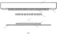
- Figure 1 schematically illustrates a three-dimensional optical component according to an exemplary embodiment of the present invention as well as a method for manufacturing such like optical component according to a preferred embodiment of the present invention.
- FIG. 1 a three-dimensional optical component 1 according to an exemplary embodiment of the present invention as well as a method for manufacturing such like optical component 1 according to a preferred embodiment of the present invention are illustrated schematically.
- Printing is carried out using a printing system comprising a print head 3 equipped with a plurality of ejection nozzles 4.
- the ejection nozzles are arranged in parallel on the lower side of the print head 3.
- Each ejection nozzle 4 is in fluid connection with at least one reservoir of printing ink (not shown) and preferably comprises piezoelectric crystals to eject droplets of printing ink from the print head 3 towards the substrate 5.
- the printing system can therefore also be referred to as droplets-on-demand inkjet printer.
- a volley of several droplets are ejected in parallel and simultaneously towards the substrate 5, so that a layer of deposited droplets arranged side by side is generated on the substrate 5.
- layers of deposited droplets are provided on top of each other.
- the printing ink comprises a transparent or trans-lucent printing ink, preferably an UV curable liquid monomer becoming a polymer if being cured.
- the print head 3 and in particular the individual ejection nozzles 4 are controlled via printing data provided in the form of an image file, e.g. a computer-aided design (CAD) file.
- the optical component 1 being printed is preferably a lens, in particular a spectacle lens.
- the printing steps and the curing steps are repeated subsequently until a desired intermediate optical component 2 being built up.
- the intermediate optical component 2 provides a flat top surface.
- at least one foil 7 is deposited during a deposition step.
- the foil 7 enhances the functionality of the optical component being built. In this way, it is advantageously possible to combine the advantages of additive manufacturing with the flexibility and quality of functional foils 7.
- Providing the same functionality through printing directly is difficult as the used printing materials have to fulfil the requirements to be useful printing inks, but on the other hand have to be materials from which the required functionalization can be derived. Separating this, the foil 7 can be manufactured from materials and in processes that optimize the quality of its function and the optical component can be manufactured from materials and in a process that optimizes the quality of the optical component.
- the at least one foil 7 is a coloured and/or a polarizing and/or a photochromic foil 7.
- a coloured and/or polarizing foil 7 reduces the transmission of light, in particular ultraviolet light, of the optical component.
- a coloured spectacle lens can thus be manufactured for practical as well as fashion purposes.
- a photochromic foil 7 changes its colour and/or transmission upon exposure to UV light.
- the photochromic foil 7 reduces its transmission through darkening in bright ambient, e.g. sunlight, conditions.
- the orientation of the foil 7 is preferably chosen such that the desired components of the ambient light are blocked.
- glare reduction can be achieved by blocking horizontally reflected sunrays, e.g. sunrays reflected from a water surface.
- special sunglasses for use in water sports etc. can be provided, for example.
- the orientation of the foil 7 has to be taken into account in the finishing process of the optical component 1, in particular during edging.
- the transmission of the coloured and/or polarizing and/or photochromic foil 7 is chosen between 8% and 80%, where a transmission between 8% and 18% is suitable for use in bright ambient light conditions, a transmission between 18% and 34% is suitable for use in intermediate ambient light conditions and a transmission between 34% and 80% is suitable for use in low ambient light conditions. Respecting these transmission intervals, sunglasses for use in different sunlight conditions are advantageously provided. Coloured, polarizing and/or photochromic foils 7 may be used to incorporate fashion and design as well.
- the last layer printed before the deposition step is not cured.
- the wet printing ink provides improved adhesion and bonding properties for the added foil 7. In this way, also air inclusions can be reduced.
- the foil 7 may be permeable to allow for the formation of bonds between the intermediate optical component built before the deposition step and the layers deposited after the deposition step.
- a vacuum is applied to the foil 7 after the deposition step to suck out air from air inclusion. These air inclusions would otherwise compromise the optical quality of the resulting optical component 1.
- the deposition step is followed by a compensation step during which tolerances on the embedded foil 7 are filled to yield an even surface.
- the printing process is continued until the final three-dimensional optical component is achieved.
- the data file controlling the printing process takes into account volume, location and orientation of the embedded foil 7.
- a frame is added to the optical component.
- This frame is either printed or provided by conventional production means. Printing of the frame can be carried out in parallel, after or before printing of the optical component.
- the foil 7 itself comprises an input unit.
- the frame comprises an input unit.
- the input unit is coupled to the foil 7.
- the input unit comprises a sensor and/or button, responsive to user input.
- the input unit comprises a light sensor, a location sensor, an accelerometer, a pressure sensor and/or an inclinometer, providing an optical component that adapts its functionality according to light intensity, wave length, location, acceleration, user input and/or tilt, for example.
- the optical component 1 comprises a power supply unit, e.g. in form of a solar cell. This unit is used to supply the input unit and, if applicable, the foil 7 with power.
- a power supply unit e.g. in form of a solar cell. This unit is used to supply the input unit and, if applicable, the foil 7 with power.
- the foil 7 is connected with the input unit and/or the power supply unit through electrical connectors.
- These electrical connectors may be printed or provided by conventional embedding techniques.
- the electrical connectors comprise conductive tracks printed from conductive printing ink.
- the conductive printing ink is a transparent conductive polymer.
- the electrical connectors can be embedded conventional copper wires or conductive tracks printed from a conventional, non-transparent conductive printing ink.
- non-transparent electrical connectors it is preferred, to hide the connectors at the edge of the optical component 1 and/or the frame, such that they are in contact with the foil 7.
- a stack of foils 7 is deposited during the deposition step on the intermediate optical component 2.
- the stack of foils 7 provides an active display embedded in the optical component 1.
- the stack of foils forms an organic light-emitting diode (OLED), in particular an active-matrix organic light-emitting diode (AMOLED).
- OLED organic light-emitting diode
- AMOLED active-matrix organic light-emitting diode
- an optical component 1 for use in augmented reality applications is advantageously provided.
- the foil 7 comprises an active liquid crystal or active fluid.
- an optical component 1 is provided, whose functionality can actively be changed, preferably through input from the input unit.
- the refractive index of the active liquid crystal can be changed. It is herewith advantageously possible to provide an optical component 1 with at least two zones of differing optical function.
- a bifocal lens is thus provided, whose second focal power can be turned on during use, e.g. reading, and can be turned off if not used.
- the transparency and/or colour of the active liquid crystal can be changed.
- the change can be induced through input from the input unit, e.g. through application of a voltage.
- an optical component 1 is advantageously provided that can be actively darkened, e.g. on user input or sensor input.
- the optical component darkens when a light sensor comprised in the input unit detects a camera flash or computer vision detection. In this way, optical components 1 granting instant privacy are provided.
Landscapes
- Engineering & Computer Science (AREA)
- Physics & Mathematics (AREA)
- Health & Medical Sciences (AREA)
- Ophthalmology & Optometry (AREA)
- Chemical & Material Sciences (AREA)
- Manufacturing & Machinery (AREA)
- Optics & Photonics (AREA)
- Materials Engineering (AREA)
- Mechanical Engineering (AREA)
- General Physics & Mathematics (AREA)
- General Health & Medical Sciences (AREA)
- Microelectronics & Electronic Packaging (AREA)
- Life Sciences & Earth Sciences (AREA)
- Wood Science & Technology (AREA)
- Organic Chemistry (AREA)
- Electromagnetism (AREA)
- Toxicology (AREA)
- Oral & Maxillofacial Surgery (AREA)
- Thermal Sciences (AREA)
Applications Claiming Priority (1)
| Application Number | Priority Date | Filing Date | Title |
|---|---|---|---|
| EP17162708 | 2017-03-24 |
Publications (1)
| Publication Number | Publication Date |
|---|---|
| EP3379324A1 true EP3379324A1 (de) | 2018-09-26 |
Family
ID=61768103
Family Applications (1)
| Application Number | Title | Priority Date | Filing Date |
|---|---|---|---|
| EP18163712.5A Pending EP3379324A1 (de) | 2017-03-24 | 2018-03-23 | Bedrucktes dreidimensionales optisches bauteil mit eingebetteter funktionsfolie und entsprechendes herstellungsverfahren |
Country Status (2)
| Country | Link |
|---|---|
| US (2) | US11554530B2 (de) |
| EP (1) | EP3379324A1 (de) |
Cited By (1)
| Publication number | Priority date | Publication date | Assignee | Title |
|---|---|---|---|---|
| US11370185B2 (en) | 2018-01-11 | 2022-06-28 | E-Vision Smart Optics, Inc. | Three-dimensional (3D) printing of electro-active lenses |
Families Citing this family (3)
| Publication number | Priority date | Publication date | Assignee | Title |
|---|---|---|---|---|
| EP3634731A1 (de) * | 2017-06-09 | 2020-04-15 | Essilor International | Verfahren und system zur herstellung einer optischen linse mit einem elektronischen bauelement |
| DE102018219578A1 (de) * | 2018-11-15 | 2020-05-20 | tooz technologies GmbH | Brillenglas, Brille und Verfahren zur Herstellung eines Brillenglases |
| EP3756872A1 (de) * | 2019-06-24 | 2020-12-30 | Essilor International | Verfahren zur herstellung eines optischen artikels mit einer funktionalsfolie |
Citations (9)
| Publication number | Priority date | Publication date | Assignee | Title |
|---|---|---|---|---|
| DE102009004377A1 (de) * | 2009-01-12 | 2010-07-22 | Rodenstock Gmbh | Verfahren zum Herstellen eines Brillenglases, Computerprogrammprodukt, Verwendung und Brillenglasherstellungsgerät |
| WO2010091888A1 (en) | 2009-02-14 | 2010-08-19 | Luxexcel Holding Bv | Device for directing light beams, illustration device, method for producing a device and an illustration device |
| WO2013167528A1 (en) | 2012-05-08 | 2013-11-14 | Luxexcel Holding B.V. | Method for printing a three-dimensional structure with smooth surfaces and printed article |
| WO2014108364A1 (en) | 2013-01-10 | 2014-07-17 | Luxexcel Holding B.V. | Method of printing an optical element |
| WO2015186010A1 (en) * | 2014-06-05 | 2015-12-10 | Optica Amuka (A.A.) Ltd. | Control of dynamic lenses |
| WO2016075563A1 (en) * | 2014-11-11 | 2016-05-19 | Indizen Optical Technologies, S.L. | Eyewear lens production by additive techniques |
| WO2016115369A1 (en) * | 2015-01-14 | 2016-07-21 | Northwestern University | Compositions, systems and methods for patient specific ophthalmic device |
| WO2016146374A1 (en) * | 2015-03-17 | 2016-09-22 | Philips Lighting Holding B.V. | Making 3d printed shapes with interconnects and embedded components. |
| EP3273290A1 (de) * | 2016-07-21 | 2018-01-24 | Carl Zeiss Vision International GmbH | Drucktinte, vorzugsweise 3d-drucktinte, brillenglas und verfahren zur herstellung eines brillenglases |
Family Cites Families (10)
| Publication number | Priority date | Publication date | Assignee | Title |
|---|---|---|---|---|
| US4300818A (en) * | 1978-03-13 | 1981-11-17 | Schachar Ronald A | Multifocal ophthalmic lens |
| JPH06202086A (ja) * | 1992-09-28 | 1994-07-22 | Nec Corp | 高分子分散型液晶光学素子 |
| US6652256B2 (en) * | 2000-10-27 | 2003-11-25 | Dorsey D. Coe | Three-dimensional model colorization during model construction from computer aided design data |
| US8858856B2 (en) * | 2008-01-08 | 2014-10-14 | Stratasys, Inc. | Method for building and using three-dimensional objects containing embedded identification-tag inserts |
| EP2878989B1 (de) * | 2013-11-29 | 2020-11-04 | Carl Zeiss Vision International GmbH | Verfahren zur Herstellung eines Brillenglases sowie Brillenglas |
| DE102014104321A1 (de) * | 2014-03-27 | 2015-10-01 | Leonhard Kurz Stiftung & Co. Kg | Formkörper und Verfahren zu dessen Herstellung |
| WO2016046216A1 (en) * | 2014-09-23 | 2016-03-31 | Philips Lighting Holding B.V. | Encapsulated materials in porous particles |
| US20170368742A1 (en) * | 2014-12-11 | 2017-12-28 | Schmutz Ip, Llc | Curable nano-composites for additive manufacturing of lenses |
| CA2999103A1 (en) * | 2015-09-16 | 2017-03-23 | E-Vision Smart Optics, Inc. | Systems, apparatus, and methods for ophthalmic lenses with wireless charging |
| JPWO2017212529A1 (ja) * | 2016-06-06 | 2019-03-28 | オリンパス株式会社 | 光学素子の製造方法、及び光学素子の製造装置 |
-
2018
- 2018-03-23 US US15/933,866 patent/US11554530B2/en active Active
- 2018-03-23 EP EP18163712.5A patent/EP3379324A1/de active Pending
-
2022
- 2022-05-23 US US17/750,538 patent/US20220281158A1/en not_active Abandoned
Patent Citations (9)
| Publication number | Priority date | Publication date | Assignee | Title |
|---|---|---|---|---|
| DE102009004377A1 (de) * | 2009-01-12 | 2010-07-22 | Rodenstock Gmbh | Verfahren zum Herstellen eines Brillenglases, Computerprogrammprodukt, Verwendung und Brillenglasherstellungsgerät |
| WO2010091888A1 (en) | 2009-02-14 | 2010-08-19 | Luxexcel Holding Bv | Device for directing light beams, illustration device, method for producing a device and an illustration device |
| WO2013167528A1 (en) | 2012-05-08 | 2013-11-14 | Luxexcel Holding B.V. | Method for printing a three-dimensional structure with smooth surfaces and printed article |
| WO2014108364A1 (en) | 2013-01-10 | 2014-07-17 | Luxexcel Holding B.V. | Method of printing an optical element |
| WO2015186010A1 (en) * | 2014-06-05 | 2015-12-10 | Optica Amuka (A.A.) Ltd. | Control of dynamic lenses |
| WO2016075563A1 (en) * | 2014-11-11 | 2016-05-19 | Indizen Optical Technologies, S.L. | Eyewear lens production by additive techniques |
| WO2016115369A1 (en) * | 2015-01-14 | 2016-07-21 | Northwestern University | Compositions, systems and methods for patient specific ophthalmic device |
| WO2016146374A1 (en) * | 2015-03-17 | 2016-09-22 | Philips Lighting Holding B.V. | Making 3d printed shapes with interconnects and embedded components. |
| EP3273290A1 (de) * | 2016-07-21 | 2018-01-24 | Carl Zeiss Vision International GmbH | Drucktinte, vorzugsweise 3d-drucktinte, brillenglas und verfahren zur herstellung eines brillenglases |
Cited By (1)
| Publication number | Priority date | Publication date | Assignee | Title |
|---|---|---|---|---|
| US11370185B2 (en) | 2018-01-11 | 2022-06-28 | E-Vision Smart Optics, Inc. | Three-dimensional (3D) printing of electro-active lenses |
Also Published As
| Publication number | Publication date |
|---|---|
| US20180272597A1 (en) | 2018-09-27 |
| US20220281158A1 (en) | 2022-09-08 |
| US11554530B2 (en) | 2023-01-17 |
Similar Documents
| Publication | Publication Date | Title |
|---|---|---|
| US20220281158A1 (en) | Printed three-dimensional optical component with embedded functional foil and corresponding manufacturing method | |
| CN105034363B (zh) | 模制本体及其制造方法 | |
| CN105229506B (zh) | 制造含有局部漂白区域的偏光元件的方法、制造偏光元件辊的方法以及制造单片式偏光元件的方法 | |
| CN105589592B (zh) | 指纹辨识装置 | |
| EP3051392B1 (de) | Berührungstafelherstellungsverfahren | |
| US9651801B2 (en) | Optical lens | |
| CN107277316B (zh) | 显示装置及其制造方法 | |
| CN110785695A (zh) | 用于眼科镜片的多功能装置 | |
| CN112123899B (zh) | 电子设备壳体及其制作方法和电子设备 | |
| JP6943763B2 (ja) | 光学エレメントを製造する方法及び表示デバイスの製造方法 | |
| JP2018506743A (ja) | 光学要素 | |
| EP3678857B1 (de) | Verfahren zur herstellung eines konformen visiers mit integrierten ophthalmischen linsen und entsprechendes visier | |
| CN110381688B (zh) | 装饰膜片、壳体组件和电子设备 | |
| CN204575983U (zh) | 立体影像显示屏 | |
| EP2738594A1 (de) | Polarisierende Linse | |
| CN107306509A (zh) | 触摸面板 | |
| KR20240068647A (ko) | 시선 추적 구성 요소를 갖는 안경 렌즈 | |
| US20210190994A1 (en) | Optical functional resin panel and method for manufacturing the same | |
| JP3132376U (ja) | 眼鏡用調光レンズおよびそれに用いられる調光フィルム | |
| US20220287186A1 (en) | Electronic device with multilayer laminate | |
| JP3852612B2 (ja) | 偏光調光レンズの製造方法 | |
| US20160274698A1 (en) | Sensor panel and method of manufacturing sensor panel | |
| CN104476867A (zh) | 移动终端保护膜、移动终端保护膜的制造方法和移动终端 | |
| US20230083247A1 (en) | Concealing non-optically transparent components of optical articles | |
| US20230176258A1 (en) | Polarized lens and method for providing a polarized lens |
Legal Events
| Date | Code | Title | Description |
|---|---|---|---|
| PUAI | Public reference made under article 153(3) epc to a published international application that has entered the european phase |
Free format text: ORIGINAL CODE: 0009012 |
|
| STAA | Information on the status of an ep patent application or granted ep patent |
Free format text: STATUS: THE APPLICATION HAS BEEN PUBLISHED |
|
| AK | Designated contracting states |
Kind code of ref document: A1 Designated state(s): AL AT BE BG CH CY CZ DE DK EE ES FI FR GB GR HR HU IE IS IT LI LT LU LV MC MK MT NL NO PL PT RO RS SE SI SK SM TR |
|
| AX | Request for extension of the european patent |
Extension state: BA ME |
|
| STAA | Information on the status of an ep patent application or granted ep patent |
Free format text: STATUS: REQUEST FOR EXAMINATION WAS MADE |
|
| STAA | Information on the status of an ep patent application or granted ep patent |
Free format text: STATUS: REQUEST FOR EXAMINATION WAS MADE |
|
| 17P | Request for examination filed |
Effective date: 20190326 |
|
| RBV | Designated contracting states (corrected) |
Designated state(s): AL AT BE BG CH CY CZ DE DK EE ES FI FR GB GR HR HU IE IS IT LI LT LU LV MC MK MT NL NO PL PT RO RS SE SI SK SM TR |
|
| STAA | Information on the status of an ep patent application or granted ep patent |
Free format text: STATUS: EXAMINATION IS IN PROGRESS |
|
| 17Q | First examination report despatched |
Effective date: 20220211 |
|
| RAP1 | Party data changed (applicant data changed or rights of an application transferred) |
Owner name: META PLATFORMS TECHNOLOGIES, LLC |