EP3678857B1 - Verfahren zur herstellung eines konformen visiers mit integrierten ophthalmischen linsen und entsprechendes visier - Google Patents
Verfahren zur herstellung eines konformen visiers mit integrierten ophthalmischen linsen und entsprechendes visier Download PDFInfo
- Publication number
- EP3678857B1 EP3678857B1 EP18762313.7A EP18762313A EP3678857B1 EP 3678857 B1 EP3678857 B1 EP 3678857B1 EP 18762313 A EP18762313 A EP 18762313A EP 3678857 B1 EP3678857 B1 EP 3678857B1
- Authority
- EP
- European Patent Office
- Prior art keywords
- visor
- ophthalmic lens
- conformal
- planar
- integrated
- Prior art date
- Legal status (The legal status is an assumption and is not a legal conclusion. Google has not performed a legal analysis and makes no representation as to the accuracy of the status listed.)
- Not-in-force
Links
- 238000004519 manufacturing process Methods 0.000 title claims description 25
- 238000007639 printing Methods 0.000 claims description 70
- 238000000034 method Methods 0.000 claims description 32
- 239000000654 additive Substances 0.000 claims description 7
- 230000000996 additive effect Effects 0.000 claims description 7
- 230000005540 biological transmission Effects 0.000 claims description 7
- 239000004973 liquid crystal related substance Substances 0.000 claims description 4
- 230000001815 facial effect Effects 0.000 claims description 3
- 230000010287 polarization Effects 0.000 claims description 3
- 238000003856 thermoforming Methods 0.000 claims description 3
- 238000007666 vacuum forming Methods 0.000 claims description 3
- 239000000976 ink Substances 0.000 description 32
- 230000003287 optical effect Effects 0.000 description 21
- 238000000151 deposition Methods 0.000 description 8
- 238000005452 bending Methods 0.000 description 4
- 230000006978 adaptation Effects 0.000 description 3
- 238000000576 coating method Methods 0.000 description 3
- 230000008021 deposition Effects 0.000 description 3
- 238000005457 optimization Methods 0.000 description 3
- 239000000758 substrate Substances 0.000 description 3
- 239000011248 coating agent Substances 0.000 description 2
- 238000012937 correction Methods 0.000 description 2
- 238000001914 filtration Methods 0.000 description 2
- 230000010354 integration Effects 0.000 description 2
- 238000003754 machining Methods 0.000 description 2
- 239000000463 material Substances 0.000 description 2
- 239000000178 monomer Substances 0.000 description 2
- 230000000750 progressive effect Effects 0.000 description 2
- 238000010146 3D printing Methods 0.000 description 1
- 230000001133 acceleration Effects 0.000 description 1
- 238000009826 distribution Methods 0.000 description 1
- 230000000694 effects Effects 0.000 description 1
- 238000005516 engineering process Methods 0.000 description 1
- 230000004886 head movement Effects 0.000 description 1
- 230000001788 irregular Effects 0.000 description 1
- 239000007788 liquid Substances 0.000 description 1
- 230000000704 physical effect Effects 0.000 description 1
- 229920000642 polymer Polymers 0.000 description 1
- 238000004513 sizing Methods 0.000 description 1
Images
Classifications
-
- A—HUMAN NECESSITIES
- A42—HEADWEAR
- A42B—HATS; HEAD COVERINGS
- A42B3/00—Helmets; Helmet covers ; Other protective head coverings
- A42B3/04—Parts, details or accessories of helmets
- A42B3/18—Face protection devices
- A42B3/22—Visors
- A42B3/225—Visors with full face protection, e.g. for industrial safety applications
-
- A—HUMAN NECESSITIES
- A42—HEADWEAR
- A42B—HATS; HEAD COVERINGS
- A42B3/00—Helmets; Helmet covers ; Other protective head coverings
- A42B3/04—Parts, details or accessories of helmets
- A42B3/18—Face protection devices
- A42B3/22—Visors
-
- B—PERFORMING OPERATIONS; TRANSPORTING
- B29—WORKING OF PLASTICS; WORKING OF SUBSTANCES IN A PLASTIC STATE IN GENERAL
- B29D—PRODUCING PARTICULAR ARTICLES FROM PLASTICS OR FROM SUBSTANCES IN A PLASTIC STATE
- B29D11/00—Producing optical elements, e.g. lenses or prisms
- B29D11/00009—Production of simple or compound lenses
- B29D11/00432—Auxiliary operations, e.g. machines for filling the moulds
-
- B—PERFORMING OPERATIONS; TRANSPORTING
- B33—ADDITIVE MANUFACTURING TECHNOLOGY
- B33Y—ADDITIVE MANUFACTURING, i.e. MANUFACTURING OF THREE-DIMENSIONAL [3-D] OBJECTS BY ADDITIVE DEPOSITION, ADDITIVE AGGLOMERATION OR ADDITIVE LAYERING, e.g. BY 3-D PRINTING, STEREOLITHOGRAPHY OR SELECTIVE LASER SINTERING
- B33Y80/00—Products made by additive manufacturing
-
- B—PERFORMING OPERATIONS; TRANSPORTING
- B29—WORKING OF PLASTICS; WORKING OF SUBSTANCES IN A PLASTIC STATE IN GENERAL
- B29C—SHAPING OR JOINING OF PLASTICS; SHAPING OF MATERIAL IN A PLASTIC STATE, NOT OTHERWISE PROVIDED FOR; AFTER-TREATMENT OF THE SHAPED PRODUCTS, e.g. REPAIRING
- B29C64/00—Additive manufacturing, i.e. manufacturing of three-dimensional [3D] objects by additive deposition, additive agglomeration or additive layering, e.g. by 3D printing, stereolithography or selective laser sintering
- B29C64/10—Processes of additive manufacturing
- B29C64/106—Processes of additive manufacturing using only liquids or viscous materials, e.g. depositing a continuous bead of viscous material
- B29C64/112—Processes of additive manufacturing using only liquids or viscous materials, e.g. depositing a continuous bead of viscous material using individual droplets, e.g. from jetting heads
-
- B—PERFORMING OPERATIONS; TRANSPORTING
- B29—WORKING OF PLASTICS; WORKING OF SUBSTANCES IN A PLASTIC STATE IN GENERAL
- B29L—INDEXING SCHEME ASSOCIATED WITH SUBCLASS B29C, RELATING TO PARTICULAR ARTICLES
- B29L2011/00—Optical elements, e.g. lenses, prisms
- B29L2011/0016—Lenses
-
- B—PERFORMING OPERATIONS; TRANSPORTING
- B33—ADDITIVE MANUFACTURING TECHNOLOGY
- B33Y—ADDITIVE MANUFACTURING, i.e. MANUFACTURING OF THREE-DIMENSIONAL [3-D] OBJECTS BY ADDITIVE DEPOSITION, ADDITIVE AGGLOMERATION OR ADDITIVE LAYERING, e.g. BY 3-D PRINTING, STEREOLITHOGRAPHY OR SELECTIVE LASER SINTERING
- B33Y50/00—Data acquisition or data processing for additive manufacturing
- B33Y50/02—Data acquisition or data processing for additive manufacturing for controlling or regulating additive manufacturing processes
Definitions
- the present invention relates to a method for producing a conformal visor with at least one ophthalmic lens and the corresponding conformal visor.
- optical surfaces are incorporated in conformal (wrap-around) visors by mounting the prescribed ophthalmic lenses as inserts into specially designed spectacle frames.
- This approach apart from requiring multiple parts and process steps, is expensive and intrusive to the user.
- conventionally manufacturing the inserted ophthalmic lenses e.g. from lens blanks through machining, results in limitations on the positioning and sizing of the optical surfaces of the conformal visor.
- the ophthalmic lens is typically thicker than the visor itself, which, in combination with the spectacle frame, results in a comparably bulky and uncomfortable conformal visor.
- Document EP 2 878 989 A1 discloses a method for producing an ophthalmic lens, wherein an additional lens element is printed on a main lens.
- Document US 2014 / 0 259 321 A1 discloses a method for manufacturing a visor, wherein the visor is deformed.
- a method for producing a conformal visor with at least one integrated ophthalmic lens comprising the following steps: providing a planar visor in a visor-providing step, printing at least one ophthalmic lens on the planar visor during a lens-integration step, deforming the planar visor comprising the at least one ophthalmic lens into a conformal visor in a deformation step, wherein, during the lens-integration step, the at least one ophthalmic lens is built up on the planar visor from layers of printing ink in an additive manufacturing scheme, wherein the layers are obtained through a targeted placement of droplets of printing ink at least partially side by side.
- the present method allows printing the at least one ophthalmic lens directly onto the visor in its still planar state.
- the visor thus serves as functional substrate for the print of the at least one ophthalmic lens. After adhesion of the printed lens to the planar visor, the visor can be deformed to obtain its desired shape.
- a planar visor with at least one integrated ophthalmic lens can thus be advantageously provided efficiently in a single process step and without the need for additional parts such as frames.
- the shape of the at least one ophthalmic lens is not limited. Nearly any shape and distribution of optical properties such as optical power can be achieved through the additive manufacturing scheme.
- Another object of the present invention is a method for producing a conformal visor with at least one integrated ophthalmic lens, comprising the following steps: printing a planar visor comprising at least one integrated ophthalmic lens during a printing step, deforming the planar visor comprising the at least one ophthalmic lens into a conformal visor in a deformation step, wherein, during the printing step, the planar visor and the at least one ophthalmic lens are built up from layers of printing ink in an additive manufacturing scheme, wherein the layers are obtained through a targeted placement of droplets of printing ink at least partially side by side.
- planar visor and the at least one ophthalmic lens are both printed in a single process step using the same setup.
- Design flexibility and customization options are advantageously maximized through the additive manufacturing of both, the planar visor as well as the at least one ophthalmic lens.
- printing a three-dimensional optical structure such as an ophthalmic lens or a visor is carried out by depositing droplets of printing ink side by side and one above the other in several consecutive depositing steps by means of a print head, wherein in each depositing step a plurality of droplets is ejected simultaneously by a plurality of ejection nozzles of the print head.
- the three-dimensional structure is thus build up layer by layer through a targeted placement of droplets of printing ink.
- the deposited droplets are at least partly cured after each depositing step in a curing step.
- the printing ink of the deposited droplets is either fully cured after each depositing step or only partly cured.
- the printing ink comprises an UV-curable liquid monomer becoming a polymer if being cured.
- the printing ink preferably comprises transparent or translucent printing ink.
- the at least one ophthalmic lens comprises spherical lenses, aspheric lenses, toric lenses, atoric lenses, gradient index lenses, lenses with integrated slab-offs or incorporated prismatic corrections.
- the at least one ophthalmic lens comprises single vision, multifocal and progressive lenses.
- the conformal visor comprises two ophthalmic lenses.
- the at least one ophthalmic lens is split into two or more entities per eye, i.e. the at least one ophthalmic lens is disconnected and not a single, connected entity. Hence, different optical functions and properties can be split spatially.
- the size, shape and position of the at least one ophthalmic lens can be highly customized.
- the planar visor comprises a formable hard coating on the side opposing the side on which the at least one ophthalmic lens is printed if the planar visor is pre-fabricated and serves as a functional substrate.
- the at least one ophthalmic lens is printed on the back side of the planar visor, i.e. such that it is closer to the wearer's eyes upon wearing.
- a first printing ink is used for printing the at least one ophthalmic lens and a second printing ink is used for printing the planar visor, if the planar visor is not pre-fabricated.
- a second printing ink is used for printing the planar visor, if the planar visor is not pre-fabricated.
- This allows to choose a printing ink that is optimally fit for its purpose for the print of each respective structure.
- the first and the second printing ink are matched according to their draw ratio.
- the printed initial planar shape of the at least one ophthalmic lens is determined taking into account the final conformal shape obtained through deformation in the deformation step.
- the initial, i.e. planar, shape of the at least one ophthalmic lens is calculated under the constraint that the desired optical properties are obtained after deformation, e.g. forming or bending, of the visor in the deformation step.
- the planar visor comprising at least one integrated ophthalmic lens is made conformal through uniaxial deformation, e.g. forming or bending, preferably along an axis that upon wearing the visor is parallel to the longitudinal axis of the wearer, during the deformation step.
- the conformity of the visor comprising at least one integrated ophthalmic lens is customized, i.e. determined depending on the facial profile of the wearer.
- planar visor comprising at least one integrated ophthalmic lens is biaxially deformed during the deformation step.
- the planar visor comprising at least one integrated ophthalmic lens is formed using thermoforming, vacuum forming or pressure forming during the deformation step.
- the planar visor comprising at least one integrated ophthalmic lens is bent during the deformation step and fixated in this state using external tension.
- the uniaxial bending results in little or no thickness reduction of the visor and the at least one ophthalmic lens.
- Displays comprise liquid crystal displays (LCDs), organic light-emitting diodes (OLEDs) as well as electrochromic displays.
- Lights preferably comprise light-emitting diodes (LEDs).
- Sensors preferably comprise sensors to sense light, visibility, temperature, pressure, humidity and acceleration.
- Transmitters preferably comprise integrated circuits (ICs) to transmit sensed data to e.g. an external device.
- a customization step is carried out prior to the printing step or visor-providing step, respectively, during which the visor and/or the at least one ophthalmic lens are customized with respect to their geometries, curvatures, the type of integrated functionality as well as the location of the at least one ophthalmic lens on the visor depending on purpose and/or wearer.
- Another object of the present invention is a conformal visor comprising at least one integrated ophthalmic lens produced by a method according to one of the claims 1 to 12.
- the conformal visor obtained in this way inherits the advantages of its production method described above.
- the conformal visor is lighter and less bulky as compared to those manufactured by methods known from the prior art.
- a highly customizable conformal visor with optical properties is provided. Customization does not only include a better adaptation to a specific user/wearer, but also a better adaptation and optimization with respect to its purpose.
- a conformal visor with at least one integrated ophthalmic lens is hence provided whose design can respond to its purpose to a much larger degree than conventionally manufactured conformal visors. Limitations associated with the conventional manufacturing methods are overcome.
- the conformal visor comprises a filter that reduces the transmission of light and/or serves as a polarization filter.
- the conformal visor comprises at least one switchable liquid crystal through which the transmission of the visor and/or the refractive index of optically active areas, in particular the at least one integrated ophthalmic lens, can be controlled electronically.
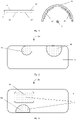
- a method for producing a conformal visor 1b with at least one integrated ophthalmic lens 2a, 2b is schematically illustrated.
- a planar visor 1a with at least one ophthalmic lens 2a, 2b is provided.
- the planar visor 1a comprises two ophthalmic lenses 2a, 2b, one for each eye. This example generalizes to other embodiments with less or more integrated ophthalmic lenses 2a, 2b.
- the planar visor 1a with ophthalmic lenses 2a, 2b is obtained in two steps: a visor-providing step and a lens-integration step.
- a pre-fabricated planar visor 1a is provided.
- the planar visor 1a has a back side 3 and a front side 4.
- “front” and “back” are determined by the proximity to the wearer's face during wear of the final, conformal visor 1b.
- the back side 3 is the side of the visor 1a, 1b that will face the wearer's face during wear.
- the visor 1a is provided inside a 3d printer.
- the at least one ophthalmic lens here two ophthalmic lenses 2a, 2b, are printed on one side of the planar visor 1a, preferably the back side 3.
- the pre-fabricated planar visor 1a serves as functional substrate in the lens-integration step.
- Printing of the ophthalmic lenses 2a, 2b comprises additively manufacturing the ophthalmic lenses 2a, 2b through a targeted placement of droplets of printing ink at least partially side by side.
- the droplets of printing ink are preferably ejected by nozzles of a print head of a 3d or droplet-on-demand printer towards the planar visor 1a.
- the ophthalmic lenses 2a, 2b are built up from layers of printing ink.
- the printing ink comprises preferably a translucent or transparent printing material.
- the printing ink comprises a UV-polymerizable monomer.
- the printing ink is tinted to achieve a filter effect, e.g. to reduce the transmission of light or light with a defined property in at least one of the ophthalmic lenses 2a, 2b.
- the deposited printing ink is cured at certain intervals. Curing may be carried out after each deposition, after deposition of a layer or at other suitable regular or irregular intervals. As is known from the prior art, curing is preferably carried out through irradiation with light, in particular UV light.
- the shape of the ophthalmic lenses 2a, 2b is determined according to its function.
- the printed shape is preferably determined taking into account the deformations that the ophthalmic lenses 2a, 2b will undergo during the deformation step. More precisely, the printed shape is preferably chosen such that the ophthalmic lenses 2a, 2b exhibit the desired optical and geometrical properties at the end of the deformation step. This includes in particular determining the thickness of the printed ophthalmic lenses 2a, 2b such that the ophthalmic lenses 2a, 2b exhibit desired prescription properties.
- the ophthalmic lenses 2a, 2b comprise any lens apt at correcting vision, in particular single vision, multifocal, progressive and gradient index lenses, as well as spherical, aspheric, toric, atoric lenses and lenses with slab-offs and incorporated prismatic corrections.
- two ophthalmic lenses 2a, 2b are printed on the planar visor 1a, one lens for each eye.
- the two ophthalmic lenses 2a, 2b are printed with a first and a second printing ink, respectively. Using different printing inks for the respective lenses, different optical properties can efficiently be achieved. For example, the first and the second printing ink differ in their refractive indices.
- the front side of the visor 1a, 1b may comprise a hard coating improving the stability and durability of the visor 1a, 1b.
- the planar visor 1a with the ophthalmic lenses 2a, 2b is obtained through a single step, the printing step.
- This method differs from the previously described method in that the planar visor 1a is not pre-fabricated but printed as well.
- the same remarks apply as made with respect to the printing of the ophthalmic lenses 2a, 2b.
- the planar visor 1a is preferably printed using a transparent or translucent printing ink.
- the printing ink used for printing the planar visor 1a differs from the printing ink used for printing at least one of ophthalmic lenses 2a, 2b in at least one property, according to a preferred embodiment.
- the two different printing inks are matched in terms of their draw ratio.
- the visor 1a and its optically active area i.e. the ophthalmic lenses 2a, 2b are tinted to achieve filtering of light, e.g. a reduction of light transmission or polarization filtering.
- the ophthalmic lenses 2a, 2b are preferably printed on the back side 3 of the visor 1a, 1b. Printing the planar visor 1a as well as the ophthalmic lenses 2a, 2b, a planar visor 1a with integrated ophthalmic lenses 2a, 2b is provided in a single process step and setup.
- the resulting product is a planar visor 1a with fully integrated ophthalmic lenses 2a, 2b.
- at least one electronic component is integrated in the visor 1a. This is preferably done after printing of the planar visor 1a is finished and before printing of the ophthalmic lenses 2a, 2b is carried out. In this way, additional functionality is added to the visor 1a, 1b. This includes, for example, displays, lights, conductive traces as well as sensors.
- switchable liquid crystals into the planar visor 1a, optical properties of the visor 1a, 1b or its optically active areas constituted by the ophthalmic lenses 2a, 2b can be electronically controlled.
- light transmission and refractive index can be controlled in this way.
- the lens-integration step and the printing step, respectively, are followed by a deformation step during which the planar visor 1a with integrated ophthalmic lenses 2a, 2b is deformed.
- the visor 1a is formed to yield a conformal visor 1b, see the right side of Figure 1 .
- the planar visor 1a is made conformal by forming it uniaxially along an axis that upon wearing of the final visor 1b is parallel to the longitudinal axis 5 of the wearer.
- conformity is being customizable depending on the facial profile of the wearer.
- the planar visor 1a is formed biaxially during the deformation step.
- the planar visor 1a with integrated ophthalmic lenses 2a, 2b is formed using for example thermoforming, vacuum forming or pressure forming.
- the planar visor 1a with integrated ophthalmic lenses 2a, 2b is bent to become conformal and is fixated in this state using external tension during and after the deformation step. Once the tension is released, the visor 1b with integrated ophthalmic lenses 2a, 2b retains its original planar state.
- the uniaxial bending results in little or no thickness reduction of the visor 1a, 1b and the integrated ophthalmic lenses 2a, 2b.
- the initial, i.e. planar, shape of the at least one ophthalmic lens 2a, 2b is calculated under the constraint that the desired optical properties are obtained after forming of the visor 1b in the deformation step.
- the initial, planar shape comprises in particular the thickness of the at least one ophthalmic lens 2a, 2b.
- the desired optical properties comprise in particular those defined in a lens prescription.
- the initial planar shape is communicated to the print head before or during the printing process through print data, e.g. in the form of CAD data and/or intensity images.
- a customization step is carried out prior to the printing step or visor-providing step, respectively.
- a highly specialized and optimized visor 1a can be obtained.
- An exemplary embodiment of the present invention in the form of such a conformal visor 1a is schematically illustrated in Figure 2 .
- Customization in the sense of the present invention comprises adaptations to the physical properties of a wearer as well as optimization with respect to a specific purpose.
- Properties that are preferably adapted depending on wearer physique and preferences, prescription data and purpose comprise the location and size of the at least one ophthalmic lens 2a, 2b, the optical properties of the at least one ophthalmic lens 2a, 2b, the geometry such as shape, thickness and curvature of the conformal visor 1b as well as additional functionality. Additional functionality is preferably lent to the conformal visor 1b with at least one integrated ophthalmic lens 2a, 2b through embedded electronic components as described above and/or functional coatings or special printing materials. E.g. the near and intermediate viewing areas defined by the at least one ophthalmic lens are preferably limited to only one side. This is particularly suitable e.g. for applications such as shooter's visors.
- the conformal visor 1b with integrated ophthalmic lens 2a, 2b is customized and optimized for shooting purposes.
- the planar visor is endowed with two ophthalmic lenses 2a, 2b according to one of the two methods described above.
- the location of the two ophthalmic lenses 2a, 2b is customized based on the application, namely rifle and pistol shooting.
- two possibilities to add near-viewing optical areas for rifle and pistol shooting are illustrated.
- a first ophthalmic lens 2a is located in the upper half of the planar visor 1a such that it lies in the view field of e.g. the left eye during rifle shooting.
- a second ophthalmic lens 2b is located in the upper half of the planar visor 1a such that it lies in the view field of e.g. the right eye during pistol shooting.
- Optical and geometrical properties of the first and second ophthalmic lenses 2a, 2b are adapted to their respective purpose.
- the first ophthalmic lens 2a comprises a side bifocal lens of a certain size and of preferably round shape.
- the second ophthalmic lens 2b designed for pistol shooting comprises for example and inverted bifocal lens.
- the second ophthalmic lens 2b for pistol shooting has a larger diameter than the first ophthalmic lens 2a for rifle shooting. It is also preferred, to print the second ophthalmic lens 2b on the upper edge of the visor lain order to account for the head movement of the wearer during aiming.
- a visor 1a according to an alternative exemplary embodiment of the present invention is schematically illustrated.
- the at least one ophthalmic lens 2 may be connected or split across the visor 1a, 1b into multiple entities.
- Figure 3 illustrates an example of a visor 1a with one ophthalmic lens 2 split across the visor 1a into multiple, e.g. two, entities.
- the at least one ophthalmic lens 2 is split into a first zone 6a and a second zone 6b.
- the first and second zone 6a, 6b are spatially separated and differ in at least one optical property. Different optical properties result, for example, from the use of different printing inks for the multiple entities, e.g.
- the first zone 6a is printed with a first printing ink and the second zone 6b is printed with a second printing ink, where the first and the second printing differ in at least one property.
- the first and the second printing ink have different refractive indices.
- the first zone 6a is designed and printed for distance viewing and the second zone 6b is designed and printed for near viewing.
- the first zone 6a is located in the upper half of the visor 1a and the second zone 6b is located in the lower half of the visor 1a.
- the inventive method lends full flexibility not only the position of the different zones 6a, 6b on the visor 1a, but also to the size and shape of the zones 6a, 6b.
- the at least one ophthalmic lens 2 is printed through a three-dimensional printing scheme
- location, size and shape can be freely chosen and also varied from visor to visor.
- the distance-viewing zone 6a has a mainly rectangular shape and covers a comparatively large section of the view field of the corresponding eye
- the near-viewing zone 6b is of circular shape and covers a comparatively small section of the lower view field of the same eye.
- the presented method allows the efficient and flexible production of highly customized conformal visors 1b, e.g. through the integration of split lenses 2.
Landscapes
- Engineering & Computer Science (AREA)
- Manufacturing & Machinery (AREA)
- Health & Medical Sciences (AREA)
- Ophthalmology & Optometry (AREA)
- Mechanical Engineering (AREA)
- Chemical & Material Sciences (AREA)
- Materials Engineering (AREA)
Claims (15)
- Verfahren zur Herstellung eines konformen Visiers (1b) mit mindestens einer integrierten ophthalmischen Linse (2, 2a, 2b), umfassend die folgenden Schritte:- Bereitstellen eines planaren Visiers (1a) in einem Visierbereitstellungsschritt,- Drucken von mindestens einer ophthalmischen Linse (2, 2a, 2b) auf das planare Visier (1a) während eines Linsenintegrationsschritts,- Verformen des planaren Visiers (1a), das die mindestens eine ophthalmische Linse (2, 2a, 2b) umfasst, zu einem konformen Visier (1b) in einem Verformungsschritt,- wobei während des Linsenintegrationsschritts die mindestens eine ophthalmische Linse (2, 2a, 2b) auf dem planaren Visier (1a) aus Schichten aus Drucktinte in einem additiven Fertigungsschema aufgebaut wird, wobei die Schichten durch gezielte Platzierung von Tröpfchen von Drucktinte mindestens teilweise nebeneinander erhalten werden.
- Verfahren zur Herstellung eines konformen Visiers (1b) mit mindestens einer integrierten ophthalmischen Linse (2, 2a, 2b), umfassend die folgenden Schritte:- Drucken von mindestens einem planaren Visier (1a), das mindestens eine integrierte ophthalmische Linse (2, 2a, 2b) umfasst, während eines Druckschritts,- Verformen des planaren Visiers (1a), das die mindestens eine ophthalmische Linse (2, 2a, 2b) umfasst, zu einem konformen Visier (1b) in einem Verformungsschritt,- wobei während des Druckschritts das planare Visier (1a) und die mindestens eine ophthalmische Linse (2, 2a, 2b) aus Schichten aus Drucktinte in einem additiven Fertigungsschema aufgebaut werden, wobei die Schichten durch gezielte Platzierung von Tröpfchen von Drucktinte mindestens teilweise nebeneinander erhalten werden.
- Verfahren nach Anspruch 2, wobei eine erste Drucktinte zum Drucken der mindestens einen ophthalmischen Linse (2, 2a, 2b) verwendet wird und eine zweite Drucktinte zum Drucken des planaren Visiers (1a) verwendet wird.
- Verfahren nach Anspruch 3, wobei die erste und die zweite Drucktinte entsprechend ihrem Ziehverhältnis abgestimmt werden.
- Verfahren nach einem der vorhergehenden Ansprüche, wobei die gedruckte planare Form der mindestens einen ophthalmischen Linse (2, 2a, 2b) unter Berücksichtigung der endgültigen konformen Formgebung der mindestens einen ophthalmischen Linse (2, 2a, 2b) bestimmt wird, die durch Verformung in dem Verformungsschritt erhalten wird.
- Verfahren nach einem der vorhergehenden Ansprüche, wobei das planare Visier (1a), das mindestens eine integrierte Linse (2, 2a, 2b) umfasst, durch uniaxiale Verformung, vorzugsweise entlang einer Achse, die beim Tragen des Visiers parallel zu der Längsachse (5) des Trägers ist, während des Verformungsschritts konform gemacht wird.
- Verfahren nach Anspruch 6, wobei die Konformität des konformen Visiers (1b), das mindestens eine integrierte ophthalmische Linse (2, 2a, 2b) umfasst, individuell angepasst wird, d. h. gemäß dem Gesichtsprofil des Trägers bestimmt wird.
- Verfahren nach einem der vorhergehenden Ansprüche, wobei das planare Visier (1a), das mindestens eine integrierte ophthalmische Linse (2, 2a, 2b) umfasst, während des Verformungsschritts biaxial verformt wird.
- Verfahren nach einem der vorhergehenden Ansprüche, wobei das planare Visier (1a), das mindestens eine integrierte ophthalmische Linse (2, 2a, 2b) umfasst, unter Verwendung von Thermoformen, Vakuumformen oder Druckformen während des Verformungsschritts geformt wird.
- Verfahren nach einem der Ansprüche 1 bis 8, wobei das planare Visier (1a), das mindestens eine integrierte ophthalmische Linse (2, 2a, 2b) umfasst, während des Verformungsschritts gebogen wird und in diesem Zustand unter Verwendung von äußerer Spannung fixiert wird.
- Verfahren nach einem der vorhergehenden Ansprüche, wobei vor dem Verformungsschritt elektronische Komponenten, wie Anzeigen und/oder Leuchten und/oder Sensoren und/oder Sender und/oder leitfähige Spuren in das planare Visier (1a) integriert werden.
- Verfahren nach einem der vorhergehenden Ansprüche, wobei ein individueller Anpassungsschritt vor dem Druckschritt beziehungsweise dem Visierbereitstellungsschritt durchgeführt wird, währenddessen das konforme Visier (1b) und/oder die mindestens eine ophthalmische Linse (2, 2a, 2b) in Bezug auf ihre Geometrien, Krümmungen, den Typ der integrierten Funktionalität sowie die Position der mindestens einen ophthalmischen Linse (2, 2a, 2b) auf dem konformen Visier (1b) in Abhängigkeit von Verwendungszweck und/oder Träger individuell angepasst wird bzw. werden.
- Konformes Visier (1b), umfassend mindestens eine integrierte ophthalmische Linse (2, 2a, 2b), die nach einem Verfahren gemäß einem der vorhergehenden Ansprüche produziert worden ist.
- Konformes Visier (1b) nach Anspruch 13, wobei das konforme Visier (1b) ein Filter umfasst, welches den Lichtdurchlass reduziert und/oder als Polarisationsfilter dient.
- Konformes Visier (1b) nach einem der Ansprüche 13 oder 14, wobei das konforme Visier (1b) mindestens einen schaltbaren Flüssigkristall umfasst, durch den der Durchlass des Visiers und/oder der Brechungsindex von optisch aktiven Bereichen, insbesondere der mindestens einen integrierten ophthalmischen Linse (2, 2a, 2b) elektronisch gesteuert werden kann.
Applications Claiming Priority (2)
| Application Number | Priority Date | Filing Date | Title |
|---|---|---|---|
| EP17189720 | 2017-09-06 | ||
| PCT/EP2018/073907 WO2019048501A1 (en) | 2017-09-06 | 2018-09-05 | METHOD FOR PRODUCING INTEGRATED OPHTHALMIC LENS VISOR COMPRISING VISOR AND CORRESPONDING VISOR |
Publications (2)
| Publication Number | Publication Date |
|---|---|
| EP3678857A1 EP3678857A1 (de) | 2020-07-15 |
| EP3678857B1 true EP3678857B1 (de) | 2022-07-27 |
Family
ID=59895054
Family Applications (1)
| Application Number | Title | Priority Date | Filing Date |
|---|---|---|---|
| EP18762313.7A Not-in-force EP3678857B1 (de) | 2017-09-06 | 2018-09-05 | Verfahren zur herstellung eines konformen visiers mit integrierten ophthalmischen linsen und entsprechendes visier |
Country Status (3)
| Country | Link |
|---|---|
| US (1) | US11744314B2 (de) |
| EP (1) | EP3678857B1 (de) |
| WO (1) | WO2019048501A1 (de) |
Families Citing this family (3)
| Publication number | Priority date | Publication date | Assignee | Title |
|---|---|---|---|---|
| US11370185B2 (en) | 2018-01-11 | 2022-06-28 | E-Vision Smart Optics, Inc. | Three-dimensional (3D) printing of electro-active lenses |
| GB2585080A (en) * | 2019-06-28 | 2020-12-30 | Hd Inspiration Holding Bv | Vision improvement system |
| WO2022155700A1 (en) * | 2021-01-21 | 2022-07-28 | Masoud Jafarzadeh | A vision correctional lens supporting attachment mechanism |
Family Cites Families (11)
| Publication number | Priority date | Publication date | Assignee | Title |
|---|---|---|---|---|
| DE102009004380B4 (de) * | 2009-01-12 | 2012-04-05 | Rodenstock Gmbh | Verfahren zum Herstellen einer individuellen Brillenfassung, Computerprogrammprodukt, Verwendung und Brillenfassungsherstellungsgerät |
| GB2495505A (en) * | 2011-10-11 | 2013-04-17 | Hd Inspiration Holding B V | Visor with photochromatic insert |
| EP2834059A1 (de) * | 2012-04-03 | 2015-02-11 | LUXeXcel Holding B.V. | Vorrichtung und verfahren zur herstellung von kundenspezifisch angefertigten brillen |
| JP2015515937A (ja) | 2012-05-08 | 2015-06-04 | ルクスエクセル ホールディング ビーヴィ | 平滑面を持つ三次元構造を印刷する方法及び印刷製品 |
| CN105431498B (zh) | 2013-06-14 | 2019-03-12 | 科思创德国股份公司 | 无方向依赖性冲击韧性的3d模制件 |
| ES2887362T3 (es) | 2013-07-31 | 2021-12-22 | Essilor Int | Fabricación aditiva para una lente oftálmica transparente |
| EP2878989B1 (de) | 2013-11-29 | 2020-11-04 | Carl Zeiss Vision International GmbH | Verfahren zur Herstellung eines Brillenglases sowie Brillenglas |
| DE102013020874A1 (de) | 2013-12-13 | 2015-06-18 | Man Truck & Bus Ag | Sonnenschutzblende an einer transparenten Scheibe, insbesondere an einer Windschutzscheibe eines Kraftfahrzeugs, insbesondere eines Nutzfahrzeugs |
| EP3119597B1 (de) | 2014-03-19 | 2024-12-04 | Essilor International | Verfahren zur herstellung einer ophthalmischen linse, die mit einem einsatz ausgestattet ist, zwischenprodukt und linsenelement |
| FR3044429B1 (fr) * | 2015-11-26 | 2018-01-05 | Ak Optique | Procede de fabrication d'une monture de lunettes sur mesure |
| US20180093418A1 (en) * | 2016-09-30 | 2018-04-05 | Velo3D, Inc. | Three-dimensional objects and their formation |
-
2018
- 2018-09-05 EP EP18762313.7A patent/EP3678857B1/de not_active Not-in-force
- 2018-09-05 US US16/644,670 patent/US11744314B2/en active Active
- 2018-09-05 WO PCT/EP2018/073907 patent/WO2019048501A1/en not_active Ceased
Also Published As
| Publication number | Publication date |
|---|---|
| US11744314B2 (en) | 2023-09-05 |
| US20200375298A1 (en) | 2020-12-03 |
| EP3678857A1 (de) | 2020-07-15 |
| WO2019048501A1 (en) | 2019-03-14 |
Similar Documents
| Publication | Publication Date | Title |
|---|---|---|
| US11809018B2 (en) | Eyewear with removably attachable top | |
| US11633928B2 (en) | Spectacle lens and method for producing a spectacle lens | |
| US12517376B2 (en) | Fabrication of see-through near eye optical module and ophthalmic lens | |
| US8827446B2 (en) | Electronic lens comprised of hybrid materials | |
| EP3678857B1 (de) | Verfahren zur herstellung eines konformen visiers mit integrierten ophthalmischen linsen und entsprechendes visier | |
| JP7446305B2 (ja) | 光学レンズの製造方法及び製造システム | |
| US20220281158A1 (en) | Printed three-dimensional optical component with embedded functional foil and corresponding manufacturing method | |
| WO2018108508A1 (en) | Printed multifocal lens and method for printing a multifocal lens | |
| US12233611B2 (en) | Functional wafers by 3D printing | |
| CN112272786A (zh) | 用于制造具有非偏振视近区的渐变色偏振镜片的方法 | |
| WO2004077127A2 (ja) | 度付眼鏡及びその製造方法 | |
| US11667093B2 (en) | Method for manufacturing one-piece corrective eyewear | |
| HK40110156A (zh) | 眼镜镜片及其生产方法 | |
| WO2020047559A2 (en) | Fabrication of see-through near eye optical module and ophthalmic lens | |
| HK40031923B (en) | Spectacle lens and method for producing same | |
| HK40031923A (en) | Spectacle lens and method for producing same | |
| HK40011538A (en) | Spectacle lens and method for producing same | |
| HK40011538B (en) | Spectacle lens and method for producing same |
Legal Events
| Date | Code | Title | Description |
|---|---|---|---|
| STAA | Information on the status of an ep patent application or granted ep patent |
Free format text: STATUS: UNKNOWN |
|
| STAA | Information on the status of an ep patent application or granted ep patent |
Free format text: STATUS: THE INTERNATIONAL PUBLICATION HAS BEEN MADE |
|
| PUAI | Public reference made under article 153(3) epc to a published international application that has entered the european phase |
Free format text: ORIGINAL CODE: 0009012 |
|
| STAA | Information on the status of an ep patent application or granted ep patent |
Free format text: STATUS: REQUEST FOR EXAMINATION WAS MADE |
|
| 17P | Request for examination filed |
Effective date: 20200330 |
|
| AK | Designated contracting states |
Kind code of ref document: A1 Designated state(s): AL AT BE BG CH CY CZ DE DK EE ES FI FR GB GR HR HU IE IS IT LI LT LU LV MC MK MT NL NO PL PT RO RS SE SI SK SM TR |
|
| AX | Request for extension of the european patent |
Extension state: BA ME |
|
| DAV | Request for validation of the european patent (deleted) | ||
| DAX | Request for extension of the european patent (deleted) | ||
| GRAP | Despatch of communication of intention to grant a patent |
Free format text: ORIGINAL CODE: EPIDOSNIGR1 |
|
| STAA | Information on the status of an ep patent application or granted ep patent |
Free format text: STATUS: GRANT OF PATENT IS INTENDED |
|
| INTG | Intention to grant announced |
Effective date: 20220214 |
|
| GRAS | Grant fee paid |
Free format text: ORIGINAL CODE: EPIDOSNIGR3 |
|
| GRAA | (expected) grant |
Free format text: ORIGINAL CODE: 0009210 |
|
| STAA | Information on the status of an ep patent application or granted ep patent |
Free format text: STATUS: THE PATENT HAS BEEN GRANTED |
|
| AK | Designated contracting states |
Kind code of ref document: B1 Designated state(s): AL AT BE BG CH CY CZ DE DK EE ES FI FR GB GR HR HU IE IS IT LI LT LU LV MC MK MT NL NO PL PT RO RS SE SI SK SM TR |
|
| REG | Reference to a national code |
Ref country code: CH Ref legal event code: EP |
|
| REG | Reference to a national code |
Ref country code: DE Ref legal event code: R096 Ref document number: 602018038486 Country of ref document: DE |
|
| REG | Reference to a national code |
Ref country code: AT Ref legal event code: REF Ref document number: 1506806 Country of ref document: AT Kind code of ref document: T Effective date: 20220815 |
|
| REG | Reference to a national code |
Ref country code: IE Ref legal event code: FG4D |
|
| REG | Reference to a national code |
Ref country code: NL Ref legal event code: FP |
|
| PGFP | Annual fee paid to national office [announced via postgrant information from national office to epo] |
Ref country code: GB Payment date: 20220930 Year of fee payment: 5 Ref country code: DE Payment date: 20220930 Year of fee payment: 5 |
|
| REG | Reference to a national code |
Ref country code: LT Ref legal event code: MG9D |
|
| PGFP | Annual fee paid to national office [announced via postgrant information from national office to epo] |
Ref country code: FR Payment date: 20220929 Year of fee payment: 5 Ref country code: BE Payment date: 20220929 Year of fee payment: 5 |
|
| PGFP | Annual fee paid to national office [announced via postgrant information from national office to epo] |
Ref country code: NL Payment date: 20220929 Year of fee payment: 5 |
|
| PG25 | Lapsed in a contracting state [announced via postgrant information from national office to epo] |
Ref country code: SE Free format text: LAPSE BECAUSE OF FAILURE TO SUBMIT A TRANSLATION OF THE DESCRIPTION OR TO PAY THE FEE WITHIN THE PRESCRIBED TIME-LIMIT Effective date: 20220727 Ref country code: RS Free format text: LAPSE BECAUSE OF FAILURE TO SUBMIT A TRANSLATION OF THE DESCRIPTION OR TO PAY THE FEE WITHIN THE PRESCRIBED TIME-LIMIT Effective date: 20220727 Ref country code: PT Free format text: LAPSE BECAUSE OF FAILURE TO SUBMIT A TRANSLATION OF THE DESCRIPTION OR TO PAY THE FEE WITHIN THE PRESCRIBED TIME-LIMIT Effective date: 20221128 Ref country code: NO Free format text: LAPSE BECAUSE OF FAILURE TO SUBMIT A TRANSLATION OF THE DESCRIPTION OR TO PAY THE FEE WITHIN THE PRESCRIBED TIME-LIMIT Effective date: 20221027 Ref country code: LV Free format text: LAPSE BECAUSE OF FAILURE TO SUBMIT A TRANSLATION OF THE DESCRIPTION OR TO PAY THE FEE WITHIN THE PRESCRIBED TIME-LIMIT Effective date: 20220727 Ref country code: LT Free format text: LAPSE BECAUSE OF FAILURE TO SUBMIT A TRANSLATION OF THE DESCRIPTION OR TO PAY THE FEE WITHIN THE PRESCRIBED TIME-LIMIT Effective date: 20220727 Ref country code: FI Free format text: LAPSE BECAUSE OF FAILURE TO SUBMIT A TRANSLATION OF THE DESCRIPTION OR TO PAY THE FEE WITHIN THE PRESCRIBED TIME-LIMIT Effective date: 20220727 Ref country code: ES Free format text: LAPSE BECAUSE OF FAILURE TO SUBMIT A TRANSLATION OF THE DESCRIPTION OR TO PAY THE FEE WITHIN THE PRESCRIBED TIME-LIMIT Effective date: 20220727 |
|
| REG | Reference to a national code |
Ref country code: AT Ref legal event code: MK05 Ref document number: 1506806 Country of ref document: AT Kind code of ref document: T Effective date: 20220727 |
|
| PG25 | Lapsed in a contracting state [announced via postgrant information from national office to epo] |
Ref country code: PL Free format text: LAPSE BECAUSE OF FAILURE TO SUBMIT A TRANSLATION OF THE DESCRIPTION OR TO PAY THE FEE WITHIN THE PRESCRIBED TIME-LIMIT Effective date: 20220727 Ref country code: IS Free format text: LAPSE BECAUSE OF FAILURE TO SUBMIT A TRANSLATION OF THE DESCRIPTION OR TO PAY THE FEE WITHIN THE PRESCRIBED TIME-LIMIT Effective date: 20221127 Ref country code: HR Free format text: LAPSE BECAUSE OF FAILURE TO SUBMIT A TRANSLATION OF THE DESCRIPTION OR TO PAY THE FEE WITHIN THE PRESCRIBED TIME-LIMIT Effective date: 20220727 Ref country code: GR Free format text: LAPSE BECAUSE OF FAILURE TO SUBMIT A TRANSLATION OF THE DESCRIPTION OR TO PAY THE FEE WITHIN THE PRESCRIBED TIME-LIMIT Effective date: 20221028 |
|
| REG | Reference to a national code |
Ref country code: DE Ref legal event code: R081 Ref document number: 602018038486 Country of ref document: DE Owner name: META PLATFORMS TECHNOLOGIES, LLC, MENLO PARK, US Free format text: FORMER OWNER: LUXEXCEL HOLDING B.V., EINDHOVEN, NL Ref country code: DE Ref legal event code: R082 Ref document number: 602018038486 Country of ref document: DE Representative=s name: MURGITROYD GERMANY PATENTANWALTSGESELLSCHAFT M, DE |
|
| PG25 | Lapsed in a contracting state [announced via postgrant information from national office to epo] |
Ref country code: SM Free format text: LAPSE BECAUSE OF FAILURE TO SUBMIT A TRANSLATION OF THE DESCRIPTION OR TO PAY THE FEE WITHIN THE PRESCRIBED TIME-LIMIT Effective date: 20220727 Ref country code: RO Free format text: LAPSE BECAUSE OF FAILURE TO SUBMIT A TRANSLATION OF THE DESCRIPTION OR TO PAY THE FEE WITHIN THE PRESCRIBED TIME-LIMIT Effective date: 20220727 Ref country code: MC Free format text: LAPSE BECAUSE OF FAILURE TO SUBMIT A TRANSLATION OF THE DESCRIPTION OR TO PAY THE FEE WITHIN THE PRESCRIBED TIME-LIMIT Effective date: 20220727 Ref country code: DK Free format text: LAPSE BECAUSE OF FAILURE TO SUBMIT A TRANSLATION OF THE DESCRIPTION OR TO PAY THE FEE WITHIN THE PRESCRIBED TIME-LIMIT Effective date: 20220727 Ref country code: CZ Free format text: LAPSE BECAUSE OF FAILURE TO SUBMIT A TRANSLATION OF THE DESCRIPTION OR TO PAY THE FEE WITHIN THE PRESCRIBED TIME-LIMIT Effective date: 20220727 Ref country code: AT Free format text: LAPSE BECAUSE OF FAILURE TO SUBMIT A TRANSLATION OF THE DESCRIPTION OR TO PAY THE FEE WITHIN THE PRESCRIBED TIME-LIMIT Effective date: 20220727 |
|
| REG | Reference to a national code |
Ref country code: CH Ref legal event code: PL |
|
| REG | Reference to a national code |
Ref country code: DE Ref legal event code: R097 Ref document number: 602018038486 Country of ref document: DE |
|
| PG25 | Lapsed in a contracting state [announced via postgrant information from national office to epo] |
Ref country code: SK Free format text: LAPSE BECAUSE OF FAILURE TO SUBMIT A TRANSLATION OF THE DESCRIPTION OR TO PAY THE FEE WITHIN THE PRESCRIBED TIME-LIMIT Effective date: 20220727 Ref country code: EE Free format text: LAPSE BECAUSE OF FAILURE TO SUBMIT A TRANSLATION OF THE DESCRIPTION OR TO PAY THE FEE WITHIN THE PRESCRIBED TIME-LIMIT Effective date: 20220727 |
|
| PLBE | No opposition filed within time limit |
Free format text: ORIGINAL CODE: 0009261 |
|
| STAA | Information on the status of an ep patent application or granted ep patent |
Free format text: STATUS: NO OPPOSITION FILED WITHIN TIME LIMIT |
|
| PG25 | Lapsed in a contracting state [announced via postgrant information from national office to epo] |
Ref country code: LU Free format text: LAPSE BECAUSE OF NON-PAYMENT OF DUE FEES Effective date: 20220905 Ref country code: AL Free format text: LAPSE BECAUSE OF FAILURE TO SUBMIT A TRANSLATION OF THE DESCRIPTION OR TO PAY THE FEE WITHIN THE PRESCRIBED TIME-LIMIT Effective date: 20220727 |
|
| 26N | No opposition filed |
Effective date: 20230502 |
|
| P01 | Opt-out of the competence of the unified patent court (upc) registered |
Effective date: 20230525 |
|
| PG25 | Lapsed in a contracting state [announced via postgrant information from national office to epo] |
Ref country code: LI Free format text: LAPSE BECAUSE OF NON-PAYMENT OF DUE FEES Effective date: 20220930 Ref country code: IE Free format text: LAPSE BECAUSE OF NON-PAYMENT OF DUE FEES Effective date: 20220905 Ref country code: CH Free format text: LAPSE BECAUSE OF NON-PAYMENT OF DUE FEES Effective date: 20220930 |
|
| REG | Reference to a national code |
Ref country code: GB Ref legal event code: 732E Free format text: REGISTERED BETWEEN 20230727 AND 20230802 |
|
| PG25 | Lapsed in a contracting state [announced via postgrant information from national office to epo] |
Ref country code: SI Free format text: LAPSE BECAUSE OF FAILURE TO SUBMIT A TRANSLATION OF THE DESCRIPTION OR TO PAY THE FEE WITHIN THE PRESCRIBED TIME-LIMIT Effective date: 20220727 |
|
| REG | Reference to a national code |
Ref country code: DE Ref legal event code: R119 Ref document number: 602018038486 Country of ref document: DE |
|
| PG25 | Lapsed in a contracting state [announced via postgrant information from national office to epo] |
Ref country code: CY Free format text: LAPSE BECAUSE OF FAILURE TO SUBMIT A TRANSLATION OF THE DESCRIPTION OR TO PAY THE FEE WITHIN THE PRESCRIBED TIME-LIMIT Effective date: 20220727 |
|
| REG | Reference to a national code |
Ref country code: NL Ref legal event code: MM Effective date: 20231001 |
|
| REG | Reference to a national code |
Ref country code: BE Ref legal event code: MM Effective date: 20230930 |
|
| GBPC | Gb: european patent ceased through non-payment of renewal fee |
Effective date: 20230905 |
|
| PG25 | Lapsed in a contracting state [announced via postgrant information from national office to epo] |
Ref country code: MK Free format text: LAPSE BECAUSE OF FAILURE TO SUBMIT A TRANSLATION OF THE DESCRIPTION OR TO PAY THE FEE WITHIN THE PRESCRIBED TIME-LIMIT Effective date: 20220727 Ref country code: IT Free format text: LAPSE BECAUSE OF FAILURE TO SUBMIT A TRANSLATION OF THE DESCRIPTION OR TO PAY THE FEE WITHIN THE PRESCRIBED TIME-LIMIT Effective date: 20220727 Ref country code: HU Free format text: LAPSE BECAUSE OF FAILURE TO SUBMIT A TRANSLATION OF THE DESCRIPTION OR TO PAY THE FEE WITHIN THE PRESCRIBED TIME-LIMIT; INVALID AB INITIO Effective date: 20180905 |
|
| PG25 | Lapsed in a contracting state [announced via postgrant information from national office to epo] |
Ref country code: NL Free format text: LAPSE BECAUSE OF NON-PAYMENT OF DUE FEES Effective date: 20231001 |
|
| PG25 | Lapsed in a contracting state [announced via postgrant information from national office to epo] |
Ref country code: TR Free format text: LAPSE BECAUSE OF FAILURE TO SUBMIT A TRANSLATION OF THE DESCRIPTION OR TO PAY THE FEE WITHIN THE PRESCRIBED TIME-LIMIT Effective date: 20220727 Ref country code: NL Free format text: LAPSE BECAUSE OF NON-PAYMENT OF DUE FEES Effective date: 20231001 |
|
| PG25 | Lapsed in a contracting state [announced via postgrant information from national office to epo] |
Ref country code: GB Free format text: LAPSE BECAUSE OF NON-PAYMENT OF DUE FEES Effective date: 20230905 |
|
| PG25 | Lapsed in a contracting state [announced via postgrant information from national office to epo] |
Ref country code: GB Free format text: LAPSE BECAUSE OF NON-PAYMENT OF DUE FEES Effective date: 20230905 Ref country code: FR Free format text: LAPSE BECAUSE OF NON-PAYMENT OF DUE FEES Effective date: 20230930 Ref country code: DE Free format text: LAPSE BECAUSE OF NON-PAYMENT OF DUE FEES Effective date: 20240403 Ref country code: BG Free format text: LAPSE BECAUSE OF FAILURE TO SUBMIT A TRANSLATION OF THE DESCRIPTION OR TO PAY THE FEE WITHIN THE PRESCRIBED TIME-LIMIT Effective date: 20220727 |
|
| PG25 | Lapsed in a contracting state [announced via postgrant information from national office to epo] |
Ref country code: BE Free format text: LAPSE BECAUSE OF NON-PAYMENT OF DUE FEES Effective date: 20230930 |
|
| PG25 | Lapsed in a contracting state [announced via postgrant information from national office to epo] |
Ref country code: MT Free format text: LAPSE BECAUSE OF FAILURE TO SUBMIT A TRANSLATION OF THE DESCRIPTION OR TO PAY THE FEE WITHIN THE PRESCRIBED TIME-LIMIT Effective date: 20220727 |