EP3379236B1 - Rastertransmission-elektronenmikroskop - Google Patents
Rastertransmission-elektronenmikroskop Download PDFInfo
- Publication number
- EP3379236B1 EP3379236B1 EP17000451.9A EP17000451A EP3379236B1 EP 3379236 B1 EP3379236 B1 EP 3379236B1 EP 17000451 A EP17000451 A EP 17000451A EP 3379236 B1 EP3379236 B1 EP 3379236B1
- Authority
- EP
- European Patent Office
- Prior art keywords
- scanning
- precession
- electron microscope
- transmission electron
- deflection system
- Prior art date
- Legal status (The legal status is an assumption and is not a legal conclusion. Google has not performed a legal analysis and makes no representation as to the accuracy of the status listed.)
- Active
Links
- 230000005540 biological transmission Effects 0.000 title claims description 26
- 238000010894 electron beam technology Methods 0.000 claims description 48
- 230000003287 optical effect Effects 0.000 claims description 38
- 238000002524 electron diffraction data Methods 0.000 description 12
- 238000002003 electron diffraction Methods 0.000 description 5
- 238000004458 analytical method Methods 0.000 description 4
- 230000000694 effects Effects 0.000 description 4
- 238000000034 method Methods 0.000 description 3
- 239000013078 crystal Substances 0.000 description 2
- 230000001419 dependent effect Effects 0.000 description 2
- 230000003993 interaction Effects 0.000 description 2
- 239000000463 material Substances 0.000 description 2
- 230000008569 process Effects 0.000 description 2
- 230000009471 action Effects 0.000 description 1
- 230000004075 alteration Effects 0.000 description 1
- 230000008901 benefit Effects 0.000 description 1
- 239000002178 crystalline material Substances 0.000 description 1
- 238000001514 detection method Methods 0.000 description 1
- 238000005259 measurement Methods 0.000 description 1
- 230000004044 response Effects 0.000 description 1
- 238000011144 upstream manufacturing Methods 0.000 description 1
Images


Classifications
-
- H—ELECTRICITY
- H01—ELECTRIC ELEMENTS
- H01J—ELECTRIC DISCHARGE TUBES OR DISCHARGE LAMPS
- H01J37/00—Discharge tubes with provision for introducing objects or material to be exposed to the discharge, e.g. for the purpose of examination or processing thereof
- H01J37/26—Electron or ion microscopes; Electron or ion diffraction tubes
- H01J37/266—Measurement of magnetic or electric fields in the object; Lorentzmicroscopy
- H01J37/268—Measurement of magnetic or electric fields in the object; Lorentzmicroscopy with scanning beams
-
- G—PHYSICS
- G01—MEASURING; TESTING
- G01N—INVESTIGATING OR ANALYSING MATERIALS BY DETERMINING THEIR CHEMICAL OR PHYSICAL PROPERTIES
- G01N23/00—Investigating or analysing materials by the use of wave or particle radiation, e.g. X-rays or neutrons, not covered by groups G01N3/00 – G01N17/00, G01N21/00 or G01N22/00
- G01N23/20—Investigating or analysing materials by the use of wave or particle radiation, e.g. X-rays or neutrons, not covered by groups G01N3/00 – G01N17/00, G01N21/00 or G01N22/00 by using diffraction of the radiation by the materials, e.g. for investigating crystal structure; by using scattering of the radiation by the materials, e.g. for investigating non-crystalline materials; by using reflection of the radiation by the materials
- G01N23/20058—Measuring diffraction of electrons, e.g. low energy electron diffraction [LEED] method or reflection high energy electron diffraction [RHEED] method
-
- H—ELECTRICITY
- H01—ELECTRIC ELEMENTS
- H01J—ELECTRIC DISCHARGE TUBES OR DISCHARGE LAMPS
- H01J37/00—Discharge tubes with provision for introducing objects or material to be exposed to the discharge, e.g. for the purpose of examination or processing thereof
- H01J37/02—Details
- H01J37/20—Means for supporting or positioning the object or the material; Means for adjusting diaphragms or lenses associated with the support
-
- H—ELECTRICITY
- H01—ELECTRIC ELEMENTS
- H01J—ELECTRIC DISCHARGE TUBES OR DISCHARGE LAMPS
- H01J37/00—Discharge tubes with provision for introducing objects or material to be exposed to the discharge, e.g. for the purpose of examination or processing thereof
- H01J37/02—Details
- H01J37/244—Detectors; Associated components or circuits therefor
-
- H—ELECTRICITY
- H01—ELECTRIC ELEMENTS
- H01J—ELECTRIC DISCHARGE TUBES OR DISCHARGE LAMPS
- H01J37/00—Discharge tubes with provision for introducing objects or material to be exposed to the discharge, e.g. for the purpose of examination or processing thereof
- H01J37/26—Electron or ion microscopes; Electron or ion diffraction tubes
- H01J37/28—Electron or ion microscopes; Electron or ion diffraction tubes with scanning beams
-
- H—ELECTRICITY
- H01—ELECTRIC ELEMENTS
- H01J—ELECTRIC DISCHARGE TUBES OR DISCHARGE LAMPS
- H01J37/00—Discharge tubes with provision for introducing objects or material to be exposed to the discharge, e.g. for the purpose of examination or processing thereof
- H01J37/26—Electron or ion microscopes; Electron or ion diffraction tubes
- H01J37/295—Electron or ion diffraction tubes
- H01J37/2955—Electron or ion diffraction tubes using scanning ray
-
- H—ELECTRICITY
- H01—ELECTRIC ELEMENTS
- H01J—ELECTRIC DISCHARGE TUBES OR DISCHARGE LAMPS
- H01J2237/00—Discharge tubes exposing object to beam, e.g. for analysis treatment, etching, imaging
- H01J2237/15—Means for deflecting or directing discharge
- H01J2237/1505—Rotating beam around optical axis
-
- H—ELECTRICITY
- H01—ELECTRIC ELEMENTS
- H01J—ELECTRIC DISCHARGE TUBES OR DISCHARGE LAMPS
- H01J2237/00—Discharge tubes exposing object to beam, e.g. for analysis treatment, etching, imaging
- H01J2237/15—Means for deflecting or directing discharge
- H01J2237/1506—Tilting or rocking beam around an axis substantially at an angle to optical axis
- H01J2237/1507—Tilting or rocking beam around an axis substantially at an angle to optical axis dynamically, e.g. to obtain same impinging angle on whole area
-
- H—ELECTRICITY
- H01—ELECTRIC ELEMENTS
- H01J—ELECTRIC DISCHARGE TUBES OR DISCHARGE LAMPS
- H01J2237/00—Discharge tubes exposing object to beam, e.g. for analysis treatment, etching, imaging
- H01J2237/15—Means for deflecting or directing discharge
- H01J2237/1508—Combined electrostatic-electromagnetic means
-
- H—ELECTRICITY
- H01—ELECTRIC ELEMENTS
- H01J—ELECTRIC DISCHARGE TUBES OR DISCHARGE LAMPS
- H01J2237/00—Discharge tubes exposing object to beam, e.g. for analysis treatment, etching, imaging
- H01J2237/26—Electron or ion microscopes
- H01J2237/28—Scanning microscopes
- H01J2237/2802—Transmission microscopes
Definitions
- the present invention relates to a scanning transmission electron microscope (STEM) adapted for observing precession electron diffraction patterns recorded from one or a multitude of positions on a specimen.
- STEM scanning transmission electron microscope
- TEM transmission electron microscope
- a beam of high energy (typically 20-300 keV) electrons is directed onto a thin specimen.
- the electrons that are scattered by the specimen are analyzed, along with other secondary signals that are produced by the interaction of the incident electrons with the specimen.
- the electrons which pass through the specimen are scattered in an angular distribution, which is dependent on the atomic structure of the specimen, the thickness of the specimen, the energy of the electrons and the relative orientation between the atomic structure and the electron beam direction.
- the measured angular distribution of the transmitted electrons is referred to as the electron diffraction (ED) pattern, because the shape of the pattern is the result of interference of the electrons scattered from different atoms in the specimen in a process known as diffraction.
- ED patterns can be used to determine the atomic structure of materials.
- the key advantage of a TEM in producing ED patterns is the possibility of focusing the incident electrons into a small area with dimensions approaching one nanometer, thus enabling the analysis of atomic structure from nanometer-sized regions. Furthermore, with the ability to systematically move the small focused incident electron beam to different positions on the specimen in a scanning transmission electron microscope (STEM), it is possible to analyze the spatial variations in atomic structure due to material characteristics such as polycrystalline grain structure and elastic and plastic strain. These measurements can be made with a spatial resolution of one nanometer or better.
- STEM scanning transmission electron microscope
- PED Precession electron diffraction
- the dynamical part of the pattern is "smeared out” and becomes a relatively uniform background behind the kinematical part of the pattern (which is generally a set of small bright spots).
- the most common pattern in which the electron beam is tilted is a so-called precession pattern, where the tilt angle relative to the microscope optical axis (the precession angle) is fixed, and the tilted beam is rotated about the optical axis by changing the azimuthal angle at a constant rate.
- the beam azimuth is typically rotated through an entire circle (360 degrees) during the recording of one ED pattern, which is then referred to as a PED pattern.
- the beam is shifted and tilted in a TEM/STEM by a two-stage deflection system, where two deflectors are positioned centered around the optical axis at different distances from the specimen upstream of where the incident beam enters the pre-field objective lens.
- the deflectors can be either electromagnetic or electrostatic.
- the balance between the two deflector stages is a fixed value (one for shift and another for tilt) which defines the beam shift/tilt "purity".
- there are two pairs of deflectors at 90 degree angles with respect to each other which can produce shift and tilt in two orthogonal directions.
- both scanning and precession movements may be provided using a STEM (simultaneously or separately), the needs concerning deflection amplitude, stability and dynamic range are different.
- the object of the present invention is to provide a scanning transmission electron microscope (STEM) configured to record precession electron diffraction (PED) patterns.
- STEM scanning transmission electron microscope
- PED precession electron diffraction
- the scanning deflection system and the precession deflection system are separated, wherein both of them are located between a sample and an electron beam source in the column of the STEM.
- these two deflection systems have independent signal generators.
- a STEM according to the invention allows to provide PED in high operating range.
- the invention is preferably used for obtaining PED patterns, it is also suitable for obtaining general scattering electron distribution images.
- the invention is related to a scanning transmission electron microscope comprising an electron beam source to generate a primary electron beam, at least one condenser lens, a scanning deflection system for shifting said primary electron beam over the sample, an objective lens for generating an electron diffraction image, a sample holder to hold a sample in the path of the primary electron beam, at least one projection lens, at least one detector to detect scattered transmitted electrons and an additional precession deflection system located between the electron beam source and the sample.
- the objective lens is usually of the in-lens type.
- the primary electron beam generated by the electron beam source is formed by means of at least one condenser lens and at least one aperture. Subsequently the primary electron beam passes the scanning deflection system and the precession deflection system.
- the scanning deflection system shifts the primary electron beam out of the optical axis in order to scan over the sample.
- the precession deflection system enables the primary electron beam to tilt and rotate around the optical axis respectively around the shifted axis. Both of these deflection systems are designed as one-stage or two-stage deflection systems, wherein every stage is able to deflect the primary electron beam in two directions (x and y axis).
- the primary electron beam After passing through the scanning deflection system and the precession deflection system, the primary electron beam is finely focused to a spot on the sample by the objective lens. Because the sample is located in the magnetic field of the objective lens, the electrons that transmitted through the sample create a diffraction image by means of magnetic field of the objective lens downstream of the sample.
- the objective lens is followed by the projection lens system.
- the projection lens system consists of at least one projection lens, but preferably consists of more projection lenses.
- the projection lens system projects the image of PED pattern on the detector, where the PED pattern is detected and can be displayed on the monitor or stored and/or further processed.
- the detector may be any commonly used two-dimensional multipixel detector.
- the scanning deflection system is preferably realized with magnetic deflectors (for example electromagnetic coils).
- the precession deflection system can be realized with either electromagnetic or electrostatic deflectors. Their signal generators may be separated from each other.
- Both scanning deflection system and precession deflection system may be arranged like two-stage deflection systems. Two stages of deflectors of these two deflection systems can be positioned concentrically in two planes perpendicular to the optical axis, so that the first stages of the scanning deflection system and the precession deflection system are placed in one plane and the second stages of the scanning deflection system and the precession deflection system are placed in the other plane. Alternatively, all deflectors may be placed separately along the optical axis.
- the STEM according to the invention may further comprise a de-scanning system and a de-precession system arranged between the sample and the projection lens system.
- These deflection systems compensate the action of the scanning deflection system and the precession deflection system and return the electron beam back to the optical axis after passing through the sample.
- the transmitted electron beam passes through the projection lenses on the optical axis, so that the aberrations are reduced.
- Said de-scanning and de-precession deflection systems can be realized similarly to the scanning deflection system and the precession deflection system, i.e. such as magnetic and/or electrostatic deflectors, respectively. They may also have independent signal generators.
- a detector scanning system for scanning the diffraction image over the detection plane of the detector. This detector scanning system allows obtaining more images within one read-out interval of the detector because the detector reads the signal in certain time intervals.
- the Figure 1 schematically illustrates the scanning transmission electron microscope (STEM) according to the invention.
- STEM scanning transmission electron microscope
- Downstream of the condenser lenses 2a , 2b , 2c there are located a scanning deflection system 4 and a precession deflection system 5 .
- Both of these deflection systems comprise two stages of deflection coils and the corresponding signal generator (not shown), each capable of deflecting the primary electron beam in two perpendicular directions.
- Two stages of deflectors of these two deflection systems 4 , 5 are positioned concentrically in two planes perpendicular to the optical axis, so that the first stages of the scanning deflection system 4 and the precession deflection system 5 are placed in one plane and the second stages of the scanning deflection system 4 and the precession deflection system 5 are placed in the other plane.
- the objective lens 6 consists of two coils and a yoke with two pole pieces. Between the pole pieces there is a gap, in which a sample holder 8 is located. Downstream of the objective lens 6 there is the de-precession system 9 and the de-scanning system 10 .
- the de-precession system 9 and the de-scanning system 10 (similarly to the scanning deflection system 4 and the precession deflection system 5 ) comprise two stages of deflection coils and signal generators (not shown).
- the scanning deflection system 4 and the precession deflection system 5 are arranged concentrically around the optical axis 7 .
- the projection lens system which consists of three projection lenses 11 .
- the electron beam source 1 generates the primary electron beam.
- the electron beam current is adjusted by the first condenser lens 2a and an aperture 3 .
- the second and the third condenser lens 2b and 2c are used to set a suitable spot size and convergence angle.
- the primary electron beam goes through the scanning deflection system 4 and the precession deflection system 5 .
- the scanning deflection system 4 shifts the primary electron beam out of the optical axis 7 in order to scan over the sample.
- the precession deflection system 5 enables the primary electron beam to tilt with respect to the optical axis 7 and to rotate the tilted primary electron beam around the optical axis 7 .
- the primary electron beam enters the objective lens 6 and it is focused on the sample.
- the sample is held by the sample holder 8 in the center of the gap, or the sample may be placed closer to the one pole piece of the objective lens 6 .
- the primary electron beam scans the sample step by step, and at every position, the primary electron beam makes the precession movement (at least one circle).
- the primary electron beam is scattered by the sample in an angular scattering distribution.
- the magnetic field of the objective lens 6 downstream of the sample generates a PED pattern close to the lower pole piece of the objective lens 6 .
- the transmitted electron beam passes the de-precession system 9 and the de-scanning system 10 .
- These systems 9 , 10 operated synchronously to the corresponding precession deflection system 5 and scanning deflection system 4 , return the transmitted electron beam back to the optical axis 7 , resulting in a stationary PED pattern, and a transmitted electron beam passing through the projection lenses 11 symmetrical to the optical axis 7 .
- the PED pattern is transferred by means of the projection lenses 11 on the detector 12 to obtain a dark field and/or bright field image, or to record a PED pattern on the camera 13.
- This arrangement allows an increase in the deflection strength of the scanning deflection system 4 in order to achieve larger scan fields. Similarly, an increase in the deflection strength of the precession deflection system 5 leads to a larger precession angle.
- the precession deflection system 5 can be used for scanning the beam as well and vice versa.
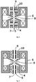
- the Figure 2 schematically illustrates the scanning deflection system 4 , the precession deflection system 5 , objective lens 6, the de-precession system 9 and the de-scanning system 10 , according to the second embodiment.
- This arrangement may replace the corresponding parts from the first embodiment.
- the objective lens 6 comprises two coils and a yoke with two pole pieces. Between the pole pieces a sample holder 8 is placed.
- Both the scanning deflection system 4 and the precession deflection system 5 are provided as two stages of electromagnetic coils. These deflectors are arranged along the optical axis 7 .
- the precession deflection system 5 is placed between the first and second stage of the scanning deflection system 4 .
- the de-scanning system 10 and the de-precession system 9 are provided as two-stage deflectors, preferably electromagnetic coils, placed along the optical axis 7 .
- the de-precession deflectors are placed between the first and the second stage of de-scanning system 10 .
- This combined electrostatic and magnetic deflection system arrangement also can be operated as Wien Filter system, where the backscattered (secondary) electrons can be separated from the primary beam.
- the Figure 3 shows another embodiment.
- an objective lens 6 a scanning deflection system 4 and a de-scanning system 10 designed as two-stage electromagnetic coils, and a precession deflection system 5 and a de-precession system 9 designed as two-stage electrostatic deflectors.
- This electrostatic deflector comprises (for deflecting in each direction) two oppositely arranged parallel deflection plates connected to a dynamically fast voltage supply to produce a high deflection speed.
- the scanning deflection system 4 and the precession deflection system 5 are located concentrically around the optical axis 7 .
- the de-scanning system 10 and the de-precession system 9 are located around the optical axis 7 .
- the sample holder 8 holds the sample in the gap of the objective lens 6 .
- the scanning deflection system 4 is designed as electromagnetic coils and the precession deflection system 5 is designed as electrostatic deflectors (similar to the third embodiment). They are located concentrically around the optical axis 7 .
- the de-scanning system 9 and the de-precession system 10 are designed according to the second embodiment, with magnetic deflectors arranged along the optical axis 7 .
- the electrostatic deflector may comprise four or eight electrodes.
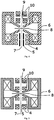
- the Figure 5 schematically illustrates another possible embodiment according to the invention.
- the scanning deflection system 4 is provided as a two-stage system of electromagnetic coils
- the precession deflection system 5 is provided as a one-stage system of electromagnetic coils. These deflectors are arranged along the optical axis 7 .
- the precession deflection system 5 is placed between the first and second stage of the scanning deflection system 4 .
- the de-scanning system 10 is provided as two-stage deflectors
- the de-precession system is provided as a one-stage system, preferably of electromagnetic coils. These systems are placed along the optical axis 7 .
- the de-precession deflectors are placed between the first and the second stage of the de-scanning system 10 .
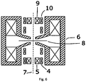
- the figure 6 schematically illustrates the embodiment with a two-stage scanning deflection system 4 and a one-stage precession deflection system 5 . These deflection systems are located concentrically around the optical axis 7 .
- the first stage of the scanning deflection system 4 is located in the same plane as the precession deflection system 5 .
- the holder 8 In the gap of the objective lens 6 is located the holder 8 to hold a sample in the path of the primary electron beam.
- the Figure 7 illustrates an embodiment of the STEM according to the presented invention in combination with a detector scanning system 14 .
- the STEM comprises an electron beam source 1 , two condenser lenses 2a , 2b and an aperture 3 , a scanning deflection system 4 and a precession deflection system 5.
- the scanning deflection system 4 and the precession deflection system 5 are performed with two-stage magnetic deflectors positioned concentrically around the optical axis 7 , e.g. in two planes perpendicular to the optical axis 7 , with separate signal generators.
- the STEM further comprises an objective lens 6 , a de-precession system 9 and a de-scanning system 10 designed as magnetic deflectors positioned along the optical axis 7 .
- the STEM further comprises two projection lenses 11 , a detector 12 and a detector scanning system 14 located between the projection lens 11 and the detector 12 .
- Electrons generated in the electron beam source 1 pass the STEM similarly to the first embodiment.
- the primary electron beam is formed by condenser lenses 2a , 2b and an aperture 3 , then it is deflected by the scanning deflection system 4 and the precession deflection system 5 . Subsequently it is focused by the objective lens 6 on the sample held in the sample holder 8 .
- the objective lens 6 forms the PED pattern from transmitted electrons.
- the axially symmetrical positions of the PED pattern are then adjusted by the de-scanning system 10 and the de-precession system 9 and magnified by the projection lenses 11 .
- the transmitted electron beam heading for the detector 12 is shifted by the detector scanning system 14 .
- the detector scanning system 14 deflects the transmitted electron beam out of the optical axis 7 , so the PED pattern may be positioned on the detector surface away from the optical axis 7 .
- the PED pattern may be shifted stepwise over the detector 12 .
- the read-out interval of the detector 12 is set up to be long enough for scanning at least two images during one read-out interval. This procedure may increase the effective recording rate of PED patterns and shorten the total operating time.
Landscapes
- Chemical & Material Sciences (AREA)
- Analytical Chemistry (AREA)
- Crystallography & Structural Chemistry (AREA)
- Physics & Mathematics (AREA)
- Health & Medical Sciences (AREA)
- Life Sciences & Earth Sciences (AREA)
- Biochemistry (AREA)
- General Health & Medical Sciences (AREA)
- General Physics & Mathematics (AREA)
- Immunology (AREA)
- Pathology (AREA)
- Analysing Materials By The Use Of Radiation (AREA)
- Length-Measuring Devices Using Wave Or Particle Radiation (AREA)
Claims (13)
- Ein Rastertransmissionselektronenmikroskop umfassend eine Elektronenstrahlquelle (1) zur Erzeugung eines Primärelektronenstrahls, mindestens eine Kondensorlinse (2), ein Scanning-Ablenksystem (4) zum Verschieben des Primärelektronenstrahls über die Probe, eine Objektivlinse (6), einen Probenhalter (8) zur Aufnahme einer Probe im Weg des Primärelektronenstrahls, mindestens eine Projektionslinse (11) und mindestens einen Detektor (12) zur Detektion der gestreuten transmittierten Elektronen, dadurch gekennzeichnet, dass das Rastertransmissionselektronenmikroskop ferner ein Präzessionsablenksystem (5), das zwischen der Strahlquelle (1) und dem Probenhalter (8) angeordnet ist.
- Das Rastertransmissionselektronenmikroskop nach Anspruch 1, dadurch gekennzeichnet, dass das Scanning-Ablenksystem (4) und das Präzessionsablenksystem (5) unabhängige Signalgeneratoren aufweisen.
- Das Rastertransmissionselektronenmikroskop nach Anspruch 1 oder 2, dadurch gekennzeichnet, dass das Präzessionsablenksystem (5) oder das Scanning-Ablenksystem (4) mindestens einen elektrostatischen Deflektor umfasst.
- Das Rastertransmissionselektronenmikroskop nach einem der Ansprüche 1 bis 3, dadurch gekennzeichnet, dass das Scanning-Ablenksystem (4) oder das Präzessionsablenksystem (5) aus zwei Stufen von Deflektoren besteht.
- Das Rastertransmissionselektronenmikroskop nach Anspruch 4, dadurch gekennzeichnet, dass mindestens eine Stufe des Scanning-Ablenksystems (4) und mindestens eine Stufe des Präzessionsablenksystems (5) konzentrisch um die optische Achse (7) angeordnet sind.
- Das Rastertransmissionselektronenmikroskop nach einem der Ansprüche 1 bis 4, dadurch gekennzeichnet, dass das Scanning-Ablenksystem (4) und das Präzessionsablenksystem (5) entlang der optischen Achse (7) angeordnet sind.
- Das Rastertransmissionselektronenmikroskop nach einem der Ansprüche 1 bis 6, dadurch gekennzeichnet, dass das Rastertransmissionselektronenmikroskop ferner ein De-Präzessionssystem (9) umfasst, das zwischen dem Probenhalter (8) und der Projektionslinse (11) angeordnet ist.
- Das Rastertransmissionselektronenmikroskop nach Anspruch 7, dadurch gekennzeichnet, dass das Rastertransmissionselektronenmikroskop ferner ein De-Scanning-System (10) umfasst, das zwischen dem Probenhalter (8) und der Projektionslinse (11) angeordnet ist.
- Das Rastertransmissionselektronenmikroskop nach Anspruch 8, dadurch gekennzeichnet, dass das De-Präzessionssystem (9) oder das De-Scanning-System (10) mindestens einen elektrostatischen Deflektor umfasst.
- Das Rastertransmissionselektronenmikroskop nach Anspruch 8 oder 9, dadurch gekennzeichnet, dass das De-Scanning-System (10) oder das De-Präzessionssystem (9) aus zwei Stufen von Deflektoren besteht.
- Das Rastertransmissionselektronenmikroskop nach Anspruch 10, dadurch gekennzeichnet, dass mindestens eine Stufe des De-Scanning-Systems (10) und mindestens eine Stufe des De-Präzessionssystems (9) konzentrisch um die optische Achse (7) angeordnet sind.
- Das Rastertransmissionselektronenmikroskop nach einem der Ansprüche 8 oder 9 oder 10, dadurch gekennzeichnet, dass das De-Scanning-System (10) und das De-Präzessionssystem (9) entlang der optischen Achse (7) angeordnet sind.
- Das Rastertransmissionselektronenmikroskop nach einem der Ansprüche 1 bis 12, dadurch gekennzeichnet, dass das Rastertransmissionselektronenmikroskop ferner ein Detektor-Scanning-System (14) umfasst.
Priority Applications (3)
| Application Number | Priority Date | Filing Date | Title |
|---|---|---|---|
| EP17000451.9A EP3379236B1 (de) | 2017-03-20 | 2017-03-20 | Rastertransmission-elektronenmikroskop |
| EP18162997.3A EP3392900B1 (de) | 2017-03-20 | 2018-03-20 | Verfahren zur automatischen ausrichtung eines rastertransmission-elektronenmikroskops für präzessionselektronenbeugungsdatenmapping |
| US15/926,623 US10636622B2 (en) | 2017-03-20 | 2018-03-20 | Scanning transmission electron microscope |
Applications Claiming Priority (1)
| Application Number | Priority Date | Filing Date | Title |
|---|---|---|---|
| EP17000451.9A EP3379236B1 (de) | 2017-03-20 | 2017-03-20 | Rastertransmission-elektronenmikroskop |
Publications (2)
| Publication Number | Publication Date |
|---|---|
| EP3379236A1 EP3379236A1 (de) | 2018-09-26 |
| EP3379236B1 true EP3379236B1 (de) | 2019-09-11 |
Family
ID=58401324
Family Applications (1)
| Application Number | Title | Priority Date | Filing Date |
|---|---|---|---|
| EP17000451.9A Active EP3379236B1 (de) | 2017-03-20 | 2017-03-20 | Rastertransmission-elektronenmikroskop |
Country Status (2)
| Country | Link |
|---|---|
| US (1) | US10636622B2 (de) |
| EP (1) | EP3379236B1 (de) |
Families Citing this family (2)
| Publication number | Priority date | Publication date | Assignee | Title |
|---|---|---|---|---|
| JP6962979B2 (ja) * | 2019-09-12 | 2021-11-05 | 日本電子株式会社 | 暗視野像の取得方法 |
| CN110687144B (zh) * | 2019-10-28 | 2022-07-22 | 长江存储科技有限责任公司 | 一种ped样品及其制备方法 |
Family Cites Families (9)
| Publication number | Priority date | Publication date | Assignee | Title |
|---|---|---|---|---|
| GB2196175B (en) * | 1986-10-03 | 1990-10-17 | Trialsite Ltd | Production of pulsed electron beams |
| ATE448561T1 (de) * | 2003-09-02 | 2009-11-15 | Nanomegas Sprl | Verfahren zur messung der beugungsmuster mit hilfe eines transmissionselektronenmikrosops zur ermittlung der kristallstruktur und vorrichtung hierfür |
| EP2351063B1 (de) | 2008-11-06 | 2016-01-27 | Nanomegas SPRL | Verfahren und vorrichtung für eine kristallstrukturanalyse mit hohem durchlass durch elektronenbrechung |
| EP2402976A1 (de) * | 2010-06-30 | 2012-01-04 | Fei Company | Verfahren zur Elektrondiffraktionstomografie |
| EP2413345B1 (de) * | 2010-07-29 | 2013-02-20 | Carl Zeiss NTS GmbH | Strahlensystem mit geladenen Teilchen |
| JP6116598B2 (ja) * | 2012-03-08 | 2017-04-19 | アップファイブ エルエルシー | 物質中のひずみを高空間分解能で測定するためのシステムおよび方法 |
| EP2642279B1 (de) * | 2012-03-19 | 2015-07-01 | Universidad de Barcelona | Verfahren und System zur Verbesserung von kennzeichnenden Spitzensignalen bei der analytischen Elektronenmikroskopie |
| EP2704177B1 (de) * | 2012-09-04 | 2014-11-26 | Fei Company | Verfahren zur Untersuchung und Korrektur von Aberrationen in einem Linsensystem mit geladenen Teilchen |
| EP3016130A1 (de) * | 2014-10-28 | 2016-05-04 | Fei Company | Zusammengesetzter Abtastpfad in einem Ladungsträgerteilchenmikroskop |
-
2017
- 2017-03-20 EP EP17000451.9A patent/EP3379236B1/de active Active
-
2018
- 2018-03-20 US US15/926,623 patent/US10636622B2/en active Active
Non-Patent Citations (1)
| Title |
|---|
| None * |
Also Published As
| Publication number | Publication date |
|---|---|
| EP3379236A1 (de) | 2018-09-26 |
| US10636622B2 (en) | 2020-04-28 |
| US20180269031A1 (en) | 2018-09-20 |
Similar Documents
| Publication | Publication Date | Title |
|---|---|---|
| US11657999B2 (en) | Particle beam system and method for the particle-optical examination of an object | |
| USRE49784E1 (en) | Apparatus of plural charged-particle beams | |
| TWI650550B (zh) | 用於高產量電子束檢測(ebi)的多射束裝置 | |
| JP5871440B2 (ja) | 走査共焦点電子顕微鏡のコントラストの向上 | |
| WO2014188882A1 (ja) | 荷電粒子線応用装置 | |
| US7022988B2 (en) | Method and apparatus for measuring physical properties of micro region | |
| KR102207766B1 (ko) | 이차 전자 광학계 & 검출 디바이스 | |
| CN108738343A (zh) | 多个带电粒子束的设备 | |
| JP5743950B2 (ja) | 走査電子顕微鏡 | |
| US9136087B2 (en) | Method of investigating and correcting aberrations in a charged-particle lens system | |
| US3702398A (en) | Electron beam apparatus | |
| US10636622B2 (en) | Scanning transmission electron microscope | |
| US20130163076A1 (en) | Transmission interference microscope | |
| US9551674B1 (en) | Method of producing an un-distorted dark field strain map at high spatial resolution through dark field electron holography | |
| JP2013058363A (ja) | 電子顕微鏡の観察方法及び電子顕微鏡 | |
| US8008629B2 (en) | Charged particle beam device and method for inspecting specimen | |
| TW201830451A (zh) | 多帶電粒子束的裝置 | |
| Williams et al. | The instrument | |
| US20230207258A1 (en) | Interference scanning transmission electron microscope | |
| Spence et al. | Large-Angle Methods |
Legal Events
| Date | Code | Title | Description |
|---|---|---|---|
| PUAI | Public reference made under article 153(3) epc to a published international application that has entered the european phase |
Free format text: ORIGINAL CODE: 0009012 |
|
| STAA | Information on the status of an ep patent application or granted ep patent |
Free format text: STATUS: REQUEST FOR EXAMINATION WAS MADE |
|
| 17P | Request for examination filed |
Effective date: 20171204 |
|
| AK | Designated contracting states |
Kind code of ref document: A1 Designated state(s): AL AT BE BG CH CY CZ DE DK EE ES FI FR GB GR HR HU IE IS IT LI LT LU LV MC MK MT NL NO PL PT RO RS SE SI SK SM TR |
|
| AX | Request for extension of the european patent |
Extension state: BA ME |
|
| RBV | Designated contracting states (corrected) |
Designated state(s): AL AT BE BG CH CY CZ DE DK EE ES FI FR GB GR HR HU IE IS IT LI LT LU LV MC MK MT NL NO PL PT RO RS SE SI SK SM TR |
|
| REG | Reference to a national code |
Ref country code: DE Ref legal event code: R079 Ref document number: 602017006806 Country of ref document: DE Free format text: PREVIOUS MAIN CLASS: G01N0023200000 Ipc: G01N0023200580 |
|
| RIC1 | Information provided on ipc code assigned before grant |
Ipc: G01N 23/20058 20180101AFI20190411BHEP Ipc: H01J 37/295 20060101ALI20190411BHEP Ipc: H01J 37/28 20060101ALI20190411BHEP Ipc: H01J 37/26 20060101ALI20190411BHEP Ipc: H01J 37/20 20060101ALI20190411BHEP Ipc: H01J 37/244 20060101ALI20190411BHEP |
|
| GRAP | Despatch of communication of intention to grant a patent |
Free format text: ORIGINAL CODE: EPIDOSNIGR1 |
|
| STAA | Information on the status of an ep patent application or granted ep patent |
Free format text: STATUS: GRANT OF PATENT IS INTENDED |
|
| GRAS | Grant fee paid |
Free format text: ORIGINAL CODE: EPIDOSNIGR3 |
|
| INTG | Intention to grant announced |
Effective date: 20190521 |
|
| GRAA | (expected) grant |
Free format text: ORIGINAL CODE: 0009210 |
|
| STAA | Information on the status of an ep patent application or granted ep patent |
Free format text: STATUS: THE PATENT HAS BEEN GRANTED |
|
| AK | Designated contracting states |
Kind code of ref document: B1 Designated state(s): AL AT BE BG CH CY CZ DE DK EE ES FI FR GB GR HR HU IE IS IT LI LT LU LV MC MK MT NL NO PL PT RO RS SE SI SK SM TR |
|
| REG | Reference to a national code |
Ref country code: GB Ref legal event code: FG4D |
|
| REG | Reference to a national code |
Ref country code: CH Ref legal event code: EP |
|
| REG | Reference to a national code |
Ref country code: AT Ref legal event code: REF Ref document number: 1179084 Country of ref document: AT Kind code of ref document: T Effective date: 20190915 |
|
| REG | Reference to a national code |
Ref country code: DE Ref legal event code: R096 Ref document number: 602017006806 Country of ref document: DE Ref country code: IE Ref legal event code: FG4D |
|
| REG | Reference to a national code |
Ref country code: NL Ref legal event code: FP |
|
| REG | Reference to a national code |
Ref country code: LT Ref legal event code: MG4D |
|
| PG25 | Lapsed in a contracting state [announced via postgrant information from national office to epo] |
Ref country code: LT Free format text: LAPSE BECAUSE OF FAILURE TO SUBMIT A TRANSLATION OF THE DESCRIPTION OR TO PAY THE FEE WITHIN THE PRESCRIBED TIME-LIMIT Effective date: 20190911 Ref country code: HR Free format text: LAPSE BECAUSE OF FAILURE TO SUBMIT A TRANSLATION OF THE DESCRIPTION OR TO PAY THE FEE WITHIN THE PRESCRIBED TIME-LIMIT Effective date: 20190911 Ref country code: BG Free format text: LAPSE BECAUSE OF FAILURE TO SUBMIT A TRANSLATION OF THE DESCRIPTION OR TO PAY THE FEE WITHIN THE PRESCRIBED TIME-LIMIT Effective date: 20191211 Ref country code: FI Free format text: LAPSE BECAUSE OF FAILURE TO SUBMIT A TRANSLATION OF THE DESCRIPTION OR TO PAY THE FEE WITHIN THE PRESCRIBED TIME-LIMIT Effective date: 20190911 Ref country code: NO Free format text: LAPSE BECAUSE OF FAILURE TO SUBMIT A TRANSLATION OF THE DESCRIPTION OR TO PAY THE FEE WITHIN THE PRESCRIBED TIME-LIMIT Effective date: 20191211 Ref country code: SE Free format text: LAPSE BECAUSE OF FAILURE TO SUBMIT A TRANSLATION OF THE DESCRIPTION OR TO PAY THE FEE WITHIN THE PRESCRIBED TIME-LIMIT Effective date: 20190911 |
|
| PG25 | Lapsed in a contracting state [announced via postgrant information from national office to epo] |
Ref country code: RS Free format text: LAPSE BECAUSE OF FAILURE TO SUBMIT A TRANSLATION OF THE DESCRIPTION OR TO PAY THE FEE WITHIN THE PRESCRIBED TIME-LIMIT Effective date: 20190911 Ref country code: GR Free format text: LAPSE BECAUSE OF FAILURE TO SUBMIT A TRANSLATION OF THE DESCRIPTION OR TO PAY THE FEE WITHIN THE PRESCRIBED TIME-LIMIT Effective date: 20191212 Ref country code: ES Free format text: LAPSE BECAUSE OF FAILURE TO SUBMIT A TRANSLATION OF THE DESCRIPTION OR TO PAY THE FEE WITHIN THE PRESCRIBED TIME-LIMIT Effective date: 20190911 Ref country code: AL Free format text: LAPSE BECAUSE OF FAILURE TO SUBMIT A TRANSLATION OF THE DESCRIPTION OR TO PAY THE FEE WITHIN THE PRESCRIBED TIME-LIMIT Effective date: 20190911 Ref country code: LV Free format text: LAPSE BECAUSE OF FAILURE TO SUBMIT A TRANSLATION OF THE DESCRIPTION OR TO PAY THE FEE WITHIN THE PRESCRIBED TIME-LIMIT Effective date: 20190911 |
|
| REG | Reference to a national code |
Ref country code: AT Ref legal event code: MK05 Ref document number: 1179084 Country of ref document: AT Kind code of ref document: T Effective date: 20190911 |
|
| PG25 | Lapsed in a contracting state [announced via postgrant information from national office to epo] |
Ref country code: AT Free format text: LAPSE BECAUSE OF FAILURE TO SUBMIT A TRANSLATION OF THE DESCRIPTION OR TO PAY THE FEE WITHIN THE PRESCRIBED TIME-LIMIT Effective date: 20190911 Ref country code: EE Free format text: LAPSE BECAUSE OF FAILURE TO SUBMIT A TRANSLATION OF THE DESCRIPTION OR TO PAY THE FEE WITHIN THE PRESCRIBED TIME-LIMIT Effective date: 20190911 Ref country code: RO Free format text: LAPSE BECAUSE OF FAILURE TO SUBMIT A TRANSLATION OF THE DESCRIPTION OR TO PAY THE FEE WITHIN THE PRESCRIBED TIME-LIMIT Effective date: 20190911 Ref country code: PT Free format text: LAPSE BECAUSE OF FAILURE TO SUBMIT A TRANSLATION OF THE DESCRIPTION OR TO PAY THE FEE WITHIN THE PRESCRIBED TIME-LIMIT Effective date: 20200113 Ref country code: PL Free format text: LAPSE BECAUSE OF FAILURE TO SUBMIT A TRANSLATION OF THE DESCRIPTION OR TO PAY THE FEE WITHIN THE PRESCRIBED TIME-LIMIT Effective date: 20190911 |
|
| PG25 | Lapsed in a contracting state [announced via postgrant information from national office to epo] |
Ref country code: SK Free format text: LAPSE BECAUSE OF FAILURE TO SUBMIT A TRANSLATION OF THE DESCRIPTION OR TO PAY THE FEE WITHIN THE PRESCRIBED TIME-LIMIT Effective date: 20190911 Ref country code: IS Free format text: LAPSE BECAUSE OF FAILURE TO SUBMIT A TRANSLATION OF THE DESCRIPTION OR TO PAY THE FEE WITHIN THE PRESCRIBED TIME-LIMIT Effective date: 20200224 Ref country code: SM Free format text: LAPSE BECAUSE OF FAILURE TO SUBMIT A TRANSLATION OF THE DESCRIPTION OR TO PAY THE FEE WITHIN THE PRESCRIBED TIME-LIMIT Effective date: 20190911 |
|
| REG | Reference to a national code |
Ref country code: DE Ref legal event code: R097 Ref document number: 602017006806 Country of ref document: DE |
|
| PLBE | No opposition filed within time limit |
Free format text: ORIGINAL CODE: 0009261 |
|
| STAA | Information on the status of an ep patent application or granted ep patent |
Free format text: STATUS: NO OPPOSITION FILED WITHIN TIME LIMIT |
|
| PG2D | Information on lapse in contracting state deleted |
Ref country code: IS |
|
| PG25 | Lapsed in a contracting state [announced via postgrant information from national office to epo] |
Ref country code: DK Free format text: LAPSE BECAUSE OF FAILURE TO SUBMIT A TRANSLATION OF THE DESCRIPTION OR TO PAY THE FEE WITHIN THE PRESCRIBED TIME-LIMIT Effective date: 20190911 Ref country code: IS Free format text: LAPSE BECAUSE OF FAILURE TO SUBMIT A TRANSLATION OF THE DESCRIPTION OR TO PAY THE FEE WITHIN THE PRESCRIBED TIME-LIMIT Effective date: 20200112 |
|
| 26N | No opposition filed |
Effective date: 20200615 |
|
| PG25 | Lapsed in a contracting state [announced via postgrant information from national office to epo] |
Ref country code: SI Free format text: LAPSE BECAUSE OF FAILURE TO SUBMIT A TRANSLATION OF THE DESCRIPTION OR TO PAY THE FEE WITHIN THE PRESCRIBED TIME-LIMIT Effective date: 20190911 |
|
| PG25 | Lapsed in a contracting state [announced via postgrant information from national office to epo] |
Ref country code: MC Free format text: LAPSE BECAUSE OF FAILURE TO SUBMIT A TRANSLATION OF THE DESCRIPTION OR TO PAY THE FEE WITHIN THE PRESCRIBED TIME-LIMIT Effective date: 20190911 |
|
| REG | Reference to a national code |
Ref country code: CH Ref legal event code: PL |
|
| REG | Reference to a national code |
Ref country code: BE Ref legal event code: MM Effective date: 20200331 |
|
| PG25 | Lapsed in a contracting state [announced via postgrant information from national office to epo] |
Ref country code: LU Free format text: LAPSE BECAUSE OF NON-PAYMENT OF DUE FEES Effective date: 20200320 |
|
| PG25 | Lapsed in a contracting state [announced via postgrant information from national office to epo] |
Ref country code: IE Free format text: LAPSE BECAUSE OF NON-PAYMENT OF DUE FEES Effective date: 20200320 Ref country code: CH Free format text: LAPSE BECAUSE OF NON-PAYMENT OF DUE FEES Effective date: 20200331 Ref country code: LI Free format text: LAPSE BECAUSE OF NON-PAYMENT OF DUE FEES Effective date: 20200331 |
|
| PG25 | Lapsed in a contracting state [announced via postgrant information from national office to epo] |
Ref country code: BE Free format text: LAPSE BECAUSE OF NON-PAYMENT OF DUE FEES Effective date: 20200331 |
|
| PG25 | Lapsed in a contracting state [announced via postgrant information from national office to epo] |
Ref country code: TR Free format text: LAPSE BECAUSE OF FAILURE TO SUBMIT A TRANSLATION OF THE DESCRIPTION OR TO PAY THE FEE WITHIN THE PRESCRIBED TIME-LIMIT Effective date: 20190911 Ref country code: MT Free format text: LAPSE BECAUSE OF FAILURE TO SUBMIT A TRANSLATION OF THE DESCRIPTION OR TO PAY THE FEE WITHIN THE PRESCRIBED TIME-LIMIT Effective date: 20190911 Ref country code: CY Free format text: LAPSE BECAUSE OF FAILURE TO SUBMIT A TRANSLATION OF THE DESCRIPTION OR TO PAY THE FEE WITHIN THE PRESCRIBED TIME-LIMIT Effective date: 20190911 |
|
| PG25 | Lapsed in a contracting state [announced via postgrant information from national office to epo] |
Ref country code: MK Free format text: LAPSE BECAUSE OF FAILURE TO SUBMIT A TRANSLATION OF THE DESCRIPTION OR TO PAY THE FEE WITHIN THE PRESCRIBED TIME-LIMIT Effective date: 20190911 |
|
| REG | Reference to a national code |
Ref country code: GB Ref legal event code: 732E Free format text: REGISTERED BETWEEN 20230928 AND 20231004 |
|
| REG | Reference to a national code |
Ref country code: NL Ref legal event code: PD Owner name: TESCAN GROUP, A.S.; CZ Free format text: DETAILS ASSIGNMENT: CHANGE OF OWNER(S), MERGE; FORMER OWNER NAME: TESCAN TEMPE, LLC. Effective date: 20231027 |
|
| REG | Reference to a national code |
Ref country code: DE Ref legal event code: R081 Ref document number: 602017006806 Country of ref document: DE Owner name: TESCAN TEMPE, LLC, TEMPE, US Free format text: FORMER OWNERS: TESCAN BRNO, S.R.O., BRNO, CZ; TESCAN TEMPE, LLC, TEMPE, ARIZ., US Ref country code: DE Ref legal event code: R081 Ref document number: 602017006806 Country of ref document: DE Owner name: TESCAN GROUP, A.S., CZ Free format text: FORMER OWNERS: TESCAN BRNO, S.R.O., BRNO, CZ; TESCAN TEMPE, LLC, TEMPE, ARIZ., US |
|
| PGFP | Annual fee paid to national office [announced via postgrant information from national office to epo] |
Ref country code: NL Payment date: 20240315 Year of fee payment: 8 |
|
| PGFP | Annual fee paid to national office [announced via postgrant information from national office to epo] |
Ref country code: DE Payment date: 20240315 Year of fee payment: 8 Ref country code: CZ Payment date: 20240314 Year of fee payment: 8 Ref country code: GB Payment date: 20240314 Year of fee payment: 8 |
|
| PGFP | Annual fee paid to national office [announced via postgrant information from national office to epo] |
Ref country code: IT Payment date: 20240315 Year of fee payment: 8 Ref country code: FR Payment date: 20240314 Year of fee payment: 8 |