EP3379062A1 - Fuel injection pump - Google Patents
Fuel injection pump Download PDFInfo
- Publication number
- EP3379062A1 EP3379062A1 EP16866238.5A EP16866238A EP3379062A1 EP 3379062 A1 EP3379062 A1 EP 3379062A1 EP 16866238 A EP16866238 A EP 16866238A EP 3379062 A1 EP3379062 A1 EP 3379062A1
- Authority
- EP
- European Patent Office
- Prior art keywords
- fuel
- spill valve
- electromagnetic spill
- valve
- drive current
- Prior art date
- Legal status (The legal status is an assumption and is not a legal conclusion. Google has not performed a legal analysis and makes no representation as to the accuracy of the status listed.)
- Withdrawn
Links
- 239000000446 fuel Substances 0.000 title claims abstract description 96
- 238000002347 injection Methods 0.000 title claims abstract description 37
- 239000007924 injection Substances 0.000 title claims abstract description 37
- 238000007493 shaping process Methods 0.000 description 8
- 238000010586 diagram Methods 0.000 description 7
- 238000000034 method Methods 0.000 description 7
- 239000000295 fuel oil Substances 0.000 description 6
- 239000003921 oil Substances 0.000 description 6
- 230000000694 effects Effects 0.000 description 4
- 238000004891 communication Methods 0.000 description 1
- 238000005516 engineering process Methods 0.000 description 1
- 238000007789 sealing Methods 0.000 description 1
- 239000000243 solution Substances 0.000 description 1
Images


Classifications
-
- F—MECHANICAL ENGINEERING; LIGHTING; HEATING; WEAPONS; BLASTING
- F02—COMBUSTION ENGINES; HOT-GAS OR COMBUSTION-PRODUCT ENGINE PLANTS
- F02D—CONTROLLING COMBUSTION ENGINES
- F02D41/00—Electrical control of supply of combustible mixture or its constituents
- F02D41/30—Controlling fuel injection
- F02D41/38—Controlling fuel injection of the high pressure type
- F02D41/40—Controlling fuel injection of the high pressure type with means for controlling injection timing or duration
- F02D41/406—Electrically controlling a diesel injection pump
-
- F—MECHANICAL ENGINEERING; LIGHTING; HEATING; WEAPONS; BLASTING
- F02—COMBUSTION ENGINES; HOT-GAS OR COMBUSTION-PRODUCT ENGINE PLANTS
- F02D—CONTROLLING COMBUSTION ENGINES
- F02D41/00—Electrical control of supply of combustible mixture or its constituents
- F02D41/02—Circuit arrangements for generating control signals
- F02D41/04—Introducing corrections for particular operating conditions
- F02D41/06—Introducing corrections for particular operating conditions for engine starting or warming up
- F02D41/062—Introducing corrections for particular operating conditions for engine starting or warming up for starting
- F02D41/064—Introducing corrections for particular operating conditions for engine starting or warming up for starting at cold start
-
- F—MECHANICAL ENGINEERING; LIGHTING; HEATING; WEAPONS; BLASTING
- F02—COMBUSTION ENGINES; HOT-GAS OR COMBUSTION-PRODUCT ENGINE PLANTS
- F02D—CONTROLLING COMBUSTION ENGINES
- F02D41/00—Electrical control of supply of combustible mixture or its constituents
- F02D41/20—Output circuits, e.g. for controlling currents in command coils
-
- F—MECHANICAL ENGINEERING; LIGHTING; HEATING; WEAPONS; BLASTING
- F02—COMBUSTION ENGINES; HOT-GAS OR COMBUSTION-PRODUCT ENGINE PLANTS
- F02D—CONTROLLING COMBUSTION ENGINES
- F02D41/00—Electrical control of supply of combustible mixture or its constituents
- F02D41/30—Controlling fuel injection
- F02D41/38—Controlling fuel injection of the high pressure type
- F02D41/40—Controlling fuel injection of the high pressure type with means for controlling injection timing or duration
- F02D41/401—Controlling injection timing
-
- F—MECHANICAL ENGINEERING; LIGHTING; HEATING; WEAPONS; BLASTING
- F02—COMBUSTION ENGINES; HOT-GAS OR COMBUSTION-PRODUCT ENGINE PLANTS
- F02D—CONTROLLING COMBUSTION ENGINES
- F02D41/00—Electrical control of supply of combustible mixture or its constituents
- F02D41/30—Controlling fuel injection
- F02D41/38—Controlling fuel injection of the high pressure type
- F02D41/40—Controlling fuel injection of the high pressure type with means for controlling injection timing or duration
- F02D41/406—Electrically controlling a diesel injection pump
- F02D41/407—Electrically controlling a diesel injection pump of the in-line type
-
- F—MECHANICAL ENGINEERING; LIGHTING; HEATING; WEAPONS; BLASTING
- F02—COMBUSTION ENGINES; HOT-GAS OR COMBUSTION-PRODUCT ENGINE PLANTS
- F02D—CONTROLLING COMBUSTION ENGINES
- F02D41/00—Electrical control of supply of combustible mixture or its constituents
- F02D41/30—Controlling fuel injection
- F02D41/38—Controlling fuel injection of the high pressure type
- F02D41/40—Controlling fuel injection of the high pressure type with means for controlling injection timing or duration
- F02D41/406—Electrically controlling a diesel injection pump
- F02D41/408—Electrically controlling a diesel injection pump of the distributing type
-
- F—MECHANICAL ENGINEERING; LIGHTING; HEATING; WEAPONS; BLASTING
- F02—COMBUSTION ENGINES; HOT-GAS OR COMBUSTION-PRODUCT ENGINE PLANTS
- F02M—SUPPLYING COMBUSTION ENGINES IN GENERAL WITH COMBUSTIBLE MIXTURES OR CONSTITUENTS THEREOF
- F02M59/00—Pumps specially adapted for fuel-injection and not provided for in groups F02M39/00 -F02M57/00, e.g. rotary cylinder-block type of pumps
- F02M59/20—Varying fuel delivery in quantity or timing
- F02M59/36—Varying fuel delivery in quantity or timing by variably-timed valves controlling fuel passages to pumping elements or overflow passages
- F02M59/366—Valves being actuated electrically
-
- F—MECHANICAL ENGINEERING; LIGHTING; HEATING; WEAPONS; BLASTING
- F02—COMBUSTION ENGINES; HOT-GAS OR COMBUSTION-PRODUCT ENGINE PLANTS
- F02M—SUPPLYING COMBUSTION ENGINES IN GENERAL WITH COMBUSTIBLE MIXTURES OR CONSTITUENTS THEREOF
- F02M59/00—Pumps specially adapted for fuel-injection and not provided for in groups F02M39/00 -F02M57/00, e.g. rotary cylinder-block type of pumps
- F02M59/44—Details, components parts, or accessories not provided for in, or of interest apart from, the apparatus of groups F02M59/02 - F02M59/42; Pumps having transducers, e.g. to measure displacement of pump rack or piston
- F02M59/46—Valves
- F02M59/466—Electrically operated valves, e.g. using electromagnetic or piezoelectric operating means
-
- F—MECHANICAL ENGINEERING; LIGHTING; HEATING; WEAPONS; BLASTING
- F02—COMBUSTION ENGINES; HOT-GAS OR COMBUSTION-PRODUCT ENGINE PLANTS
- F02D—CONTROLLING COMBUSTION ENGINES
- F02D41/00—Electrical control of supply of combustible mixture or its constituents
- F02D41/20—Output circuits, e.g. for controlling currents in command coils
- F02D2041/202—Output circuits, e.g. for controlling currents in command coils characterised by the control of the circuit
- F02D2041/2034—Control of the current gradient
-
- F—MECHANICAL ENGINEERING; LIGHTING; HEATING; WEAPONS; BLASTING
- F02—COMBUSTION ENGINES; HOT-GAS OR COMBUSTION-PRODUCT ENGINE PLANTS
- F02D—CONTROLLING COMBUSTION ENGINES
- F02D41/00—Electrical control of supply of combustible mixture or its constituents
- F02D41/20—Output circuits, e.g. for controlling currents in command coils
- F02D2041/202—Output circuits, e.g. for controlling currents in command coils characterised by the control of the circuit
- F02D2041/2055—Output circuits, e.g. for controlling currents in command coils characterised by the control of the circuit with means for determining actual opening or closing time
-
- F—MECHANICAL ENGINEERING; LIGHTING; HEATING; WEAPONS; BLASTING
- F02—COMBUSTION ENGINES; HOT-GAS OR COMBUSTION-PRODUCT ENGINE PLANTS
- F02D—CONTROLLING COMBUSTION ENGINES
- F02D41/00—Electrical control of supply of combustible mixture or its constituents
- F02D41/20—Output circuits, e.g. for controlling currents in command coils
- F02D2041/202—Output circuits, e.g. for controlling currents in command coils characterised by the control of the circuit
- F02D2041/2058—Output circuits, e.g. for controlling currents in command coils characterised by the control of the circuit using information of the actual current value
-
- F—MECHANICAL ENGINEERING; LIGHTING; HEATING; WEAPONS; BLASTING
- F02—COMBUSTION ENGINES; HOT-GAS OR COMBUSTION-PRODUCT ENGINE PLANTS
- F02D—CONTROLLING COMBUSTION ENGINES
- F02D2200/00—Input parameters for engine control
- F02D2200/02—Input parameters for engine control the parameters being related to the engine
- F02D2200/06—Fuel or fuel supply system parameters
- F02D2200/0606—Fuel temperature
-
- F—MECHANICAL ENGINEERING; LIGHTING; HEATING; WEAPONS; BLASTING
- F02—COMBUSTION ENGINES; HOT-GAS OR COMBUSTION-PRODUCT ENGINE PLANTS
- F02D—CONTROLLING COMBUSTION ENGINES
- F02D2200/00—Input parameters for engine control
- F02D2200/02—Input parameters for engine control the parameters being related to the engine
- F02D2200/10—Parameters related to the engine output, e.g. engine torque or engine speed
- F02D2200/101—Engine speed
-
- Y—GENERAL TAGGING OF NEW TECHNOLOGICAL DEVELOPMENTS; GENERAL TAGGING OF CROSS-SECTIONAL TECHNOLOGIES SPANNING OVER SEVERAL SECTIONS OF THE IPC; TECHNICAL SUBJECTS COVERED BY FORMER USPC CROSS-REFERENCE ART COLLECTIONS [XRACs] AND DIGESTS
- Y02—TECHNOLOGIES OR APPLICATIONS FOR MITIGATION OR ADAPTATION AGAINST CLIMATE CHANGE
- Y02T—CLIMATE CHANGE MITIGATION TECHNOLOGIES RELATED TO TRANSPORTATION
- Y02T10/00—Road transport of goods or passengers
- Y02T10/10—Internal combustion engine [ICE] based vehicles
- Y02T10/40—Engine management systems
Definitions
- the present invention relates to a technology of a fuel injection pump.
- a fuel injection pump provided in a diesel engine has traditionally been well-known. Further, an electromagnetic spill valve provided in the fuel injection pump has also been well-known. To the electromagnetic spill valve, drive current whose current waveform is shaped by a control device is applied, and a fuel injection amount is adjusted by releasing pressurized fuel with opening/closing of the valve (e.g., see Patent Literature 1; hereinafter PTL 1).
- the control device includes a full automatic mode and a manual mode as means for shaping the current waveform of the drive current of the electromagnetic spill valve.
- a valve-close (maximum lift) timing of the electromagnetic spill valve is detected, and an optimum current waveform of the drive current is formed based on the detected maximum lift timing.
- the manual mode only the current waveform of the preset drive current is formed.
- An object of the present invention is to provide a fuel injection pump that can control the valve behavior by accurately detecting a valve-close timing even if the fuel viscosity is high.
- a fuel injection pump is a fuel injection pump provided in a diesel engine, including: an electromagnetic spill valve configured to adjust a fuel injection amount by releasing pressurized fuel with opening/closing of a valve body; and a control device configured to form a current waveform of drive current of the electromagnetic spill valve, wherein the control device, during a warm state, detects a valve-close timing of the electromagnetic spill valve, forms an optimum current waveform of drive current based on the detected valve-close timing, and applies drive current with thus formed optimum current waveform to the electromagnetic spill valve, whereas, during a cold state, applies only drive current with a pre-set current waveform to the electromagnetic spill valve.
- the fuel injection pump of the aspect of the present invention preferably includes a fuel temperature detector configured to detect a fuel temperature of fuel passing through the electromagnetic spill valve, wherein the control device determines, as the warm state, if the fuel temperature equals to or higher than a predetermined temperature, and determines, as the cold state, if the fuel temperature is less than the predetermined temperature.
- the fuel injection pump of the aspect of the present invention is preferably such that the control device determines, as the warm state, if an engine speed at the time of starting the engine is equal to or higher than a predetermined engine speed, and determines, as the cold state, if the engine speed at the time of starting the engine is lower than the predetermined engine speed.
- the fuel injection pump of the aspect of the present invention is preferably such that the control device determines, as the warm state, after elapse of a predetermined period from the starting of the engine, and determines, as the cold state, until the elapse of the predetermined period.
- a valve-close timing can be accurately detected, and the valve behavior can be controlled, even if the fuel viscosity is high.
- FIG. 1 schematically shows a structure of a fuel injection pump 100.
- the fuel injection pump 100 of the present embodiment is to be provided in each cylinder of a large diesel engine mounted in a ship. It is supposed that the fuel injection pump 100 of the present embodiment uses fuel oil C as its fuel.
- the fuel injection pump 100 is connected to a not-shown low-pressure pump (feed pump) and pressurizes and feeds fuel from the low-pressure pump to a not-shown fuel injection nozzle.
- the fuel injection pump 100 includes a pump main body part 10, an electromagnetic spill valve 20, and a two-way delivery valve part 30.
- the pump main body part 10 includes: a pump main body upper portion 11 formed in a substantially cylindrical shape; a barrel 12 having therein a plunger 13 which is provided in such a manner as to be slidable in an axial direction; the plunger 13 which pressurizes fuel; a plunger spring 14 which biases the plunger 13 downwards; a tappet 15 for transmitting a pressing force from a not-shown cam to the plunger 13; and the not-shown cam.
- a plunger hole 12A for providing the plunger 13 therein is formed with its lower end portion opened.
- a first fuel supply path 12B is formed so as to extend in the vertical direction.
- An upper end surface of the plunger 13 and the plunger hole 12A form a pressurizing chamber 16.
- a first spill-oil discharge passage 12C is formed so as to extend substantially in the vertical direction, on a radially outside of the first fuel supply path 12B.
- the electromagnetic spill valve 20 adjusts the fuel injection amount and the injection timing of the fuel injection pump 100.
- the electromagnetic spill valve 20 includes a housing 21, an insert piece 22, a spill valve body 23, an end cap 24, and a solenoid 25.
- the housing 21 is a structure that constitutes the main body portion of the electromagnetic spill valve 20.
- the housing 21 is formed in a substantially rectangular parallelepiped shape.
- a two-way delivery valve spring chamber 21A is formed in the vertical direction.
- a second fuel supply path 21B is formed in the vertical direction.
- a second spill-oil discharge passage 21C is formed in the vertical direction, on the left side of the second fuel supply path 21B.
- the two-way delivery valve part 30 ejects fuel or maintains a post-injection fuel pressure inside a high-pressure pipe joint 35 at a predetermined value.
- the two-way delivery valve part 30 includes a two-way delivery valve main body 32, an ejection valve 33, a two-way delivery valve 34, and the like. Further, the two-way delivery valve part 30 is connected to the high-pressure pipe joint 35.
- the fuel in the pressurizing chamber 16 is pressurized by the plunger 13 which slides upward with the rotation of a not-shown cam and is fed sequentially from the pressurizing chamber 16 to the first fuel supply path 12B, and the second fuel supply path 21B of the housing 21.
- the solenoid 25 of the electromagnetic spill valve 20 is excited based on a signal from an Engine Control Unit (Hereinafter, ECU) 50 (see FIG. 2 ).
- ECU Engine Control Unit
- the spill valve body 23 of the electromagnetic spill valve 20 is slid rightward by the suction force of the solenoid 25. Then, a sealing surface of the spill valve body 23 is seated on a valve seat of the insert piece 22.
- the communication between the second fuel supply path 21B and the second spill-oil discharge passage 21C of the housing 21 is shuttered, and the fuel pressure in the second fuel supply passage 21B is maintained without being released through the second spill-oil discharge passage 21C.
- the pressurized fuel is filled from the pressurizing chamber 16 into the two-way delivery valve spring chamber 21A through the first fuel supply path 12B and the second fuel supply path 21B. That is, the electromagnetic spill valve 20 is closed and the fuel can be supplied.
- the solenoid 25 of the electromagnetic spill valve 20 is demagnetized based on a signal from the ECU 50 (see FIG. 2 ).
- the spill valve body 23 of the electromagnetic spill valve 20 is slid leftward until it abuts an abut surface of the end cap 24 of the spill valve body 23.
- the second fuel supply path 21B and the second spill-oil discharge passage 21C of the housing 21 are communicated with each other, and the fuel pressure in the second fuel supply passage 21B is released through the second spill-oil discharge passage 21C.
- the following describes a control structure of the electromagnetic spill valve 20, with reference to FIG. 2 .
- control structure of the electromagnetic spill valve 20 is represented by a block diagram.
- the electromagnetic spill valve 20 is connected to the ECU 50 via a current detector 55. To the electromagnetic spill valve 20, drive current whose current waveform is shaped by the ECU50 is applied.
- the ECU 50 is connected to an engine speed sensor 51 and a fuel temperature sensor 52.
- the current detector 55 detects the flowing current supplied to the electromagnetic spill valve 20. It should be noted that the flowing current includes the drive current, the counter electromotive force of the solenoid 25, and the like.
- the engine speed sensor 51 is provided nearby a flywheel of the diesel engine and detects the engine speed NE.
- the fuel temperature sensor 52 is provided in a fuel passage nearby the electromagnetic spill valve 20, and detects the fuel temperature TN.
- the ECU50 inclusively controls the diesel engine and shapes the current waveform of the drive current which drives the electromagnetic spill valve 20. Further, the ECU 50 includes a full automatic mode and a manual mode as means for shaping the current waveform of the drive current.
- FIG. 3(A) is a time series graph showing the lift amount of the spill valve body 23 of the electromagnetic spill valve 20
- FIG. 3(B) is a time series graph showing the flowing current (solid line) and the drive current (broken line) of the electromagnetic spill valve 20.
- a time lag occurs in the actual behavior of the spill valve body 23 of the electromagnetic spill valve 20 with respect to the flowing current of the electromagnetic spill valve 20.
- the current detector 55 detects current values IB, IC and predetermined times TB, TC, and TD and performs feedback control for correcting them to an optimum value. Specifically, the current waveform between TB and TC is fed back, and the same current waveform with the time axis of TC as the axis of symmetry is formed between TC and TD.
- TA and TE are values determined based on a map, according to the engine load.
- the current waveform between TB-TC and the current waveform between TC-TD forms an asymmetrical V-shape with respect to the time axis of TC, as compared with a symmetrical V-shape formed when the fuel viscosity is low.
- the current waveform of the drive current is formed only by a pre-set current values IB and IC, and predetermined times TB, TC, and TD. It should be noted that the pre-set current values IB and IC, and the predetermined times TB, TC, and TD are stored in the ECU50 in advance.
- FIG. 4 is a flowchart showing a flow of the drive current control S100.
- the ECU 50 switches the means for shaping the current waveform between the full automatic mode and the manual mode based on the fuel temperature TN.
- step S110 the ECU 50 determines whether the fuel temperature TN is higher than a predetermined temperature TN1. The process proceeds to step S120 if the fuel temperature TN is higher than the predetermined temperature TN1, whereas the process proceeds to step S130 if the fuel temperature TN is equal to or lower than the predetermined temperature TN1.
- step S120 the ECU50 shapes the current waveform of the drive current in the full automatic mode.
- step S130 the ECU50 shapes the current waveform of the drive current in the manual mode.
- the predetermined temperature TN1 is 110 °C.
- the current waveform of the current flowing in the electromagnetic spill valve 20 can be prevented from collapsing, even if the fuel viscosity is high. That is, when the fuel temperature TN is equal to or lower than the predetermined temperature TN1, the fuel viscosity of the fuel oil C is expected to be high.
- the means for shaping the current waveform of the drive current to the manual mode, and the current waveform of the current flowing in the electromagnetic spill valve 20 can be prevented from collapsing.
- the following describes a drive current control S200, with reference to FIG. 5 .
- FIG. 5 is a flowchart showing a flow of the drive current control S200.
- the ECU 50 switches the means for shaping the current waveform between the full automatic mode and the manual mode based on the engine speed NE.
- step S210 the ECU 50 determines whether the engine speed NE is higher than a predetermined engine speed NE1. The process proceeds to step S220 if the fuel engine speed NE is higher than the predetermined engine speed NE1, whereas the process proceeds to step S230 if the engine speed NE is equal to or lower than the predetermined engine speed NE1.
- step S220 the ECU50 shapes the current waveform of the drive current in the full automatic mode.
- step S230 the ECU50 shapes the current waveform of the drive current in the manual mode.
- the predetermined engine speed NE1 is 720 rpm.
- the current waveform of the current flowing in the electromagnetic spill valve 20 can be prevented from collapsing, even if the fuel viscosity is high. That is, when the engine speed NE is equal to or lower than the predetermined engine speed NE1, the fuel viscosity of the fuel oil C is expected to be high.
- the means for shaping the current waveform of the drive current to the manual mode, and the current waveform of the current flowing in the electromagnetic spill valve 20 can be prevented from collapsing.
- the following describes a drive current control S300, with reference to FIG. 6 .
- FIG. 6 is a flowchart showing a flow of the drive current control S300.
- the ECU 50 switches the means for shaping the current waveform between the full automatic mode and the manual mode based on the time elapsed after starting of the engine.
- step S310 the ECU 50 determines whether the diesel engine has been started. When the diesel engine is started, the process proceeds to step S320.
- step S320 the ECU 50 determines whether 10 minutes have elapsed from the starting of the engine. The process proceeds to S330 if 10 minutes has elapsed from the starting of the engine, whereas the process proceeds to step S340 if 10 minutes has not yet elapsed from the start of the engine.
- step S330 the ECU50 shapes the current waveform of the drive current in the full automatic mode.
- step S340 the ECU50 shapes the current waveform of the drive current in the manual mode.
- the current waveform of the current flowing in the electromagnetic spill valve 20 can be prevented from collapsing, even if the fuel viscosity is high. That is, if the time elapsed from the starting of the diesel engine is less than 10 minutes, the fuel viscosity of the fuel oil C is expected to be high.
- the means for shaping the current waveform of the drive current to the manual mode, and the current waveform of the current flowing in the electromagnetic spill valve 20 can be prevented from collapsing.
- the present invention is applicable to a fuel injection pump.
Abstract
Description
- The present invention relates to a technology of a fuel injection pump.
- A fuel injection pump provided in a diesel engine has traditionally been well-known. Further, an electromagnetic spill valve provided in the fuel injection pump has also been well-known. To the electromagnetic spill valve, drive current whose current waveform is shaped by a control device is applied, and a fuel injection amount is adjusted by releasing pressurized fuel with opening/closing of the valve (e.g., see
Patent Literature 1; hereinafter PTL 1). - Traditionally, the control device includes a full automatic mode and a manual mode as means for shaping the current waveform of the drive current of the electromagnetic spill valve. In the full automatic mode, a valve-close (maximum lift) timing of the electromagnetic spill valve is detected, and an optimum current waveform of the drive current is formed based on the detected maximum lift timing. In the manual mode, only the current waveform of the preset drive current is formed.
- However, in cases where the diesel engine is operated in a cold state by using fuel oil C having a relatively high viscosity as the fuel, and the current waveform of the drive current of the electromagnetic spill valve is formed in the full automatic mode, a phenomenon in which the drive current collapses may take place. This phenomenon is thought to be caused by the following reason. Namely, a high viscosity of the fuel oil C during the cold state slows down the behavior of the electromagnetic spill valve, and the maximum lift timing cannot be detected.
- Further, when such a phenomenon takes place in the diesel engine, it is confirmed that the normal waveform of the flowing current is not restored even if the engine is operated for a long time in a steady state (i.e., in the state where the fuel viscosity is sufficiently low).
- PTL 1: Japanese Examined Patent Application Publication No.
H6-003164 (1994 - An object of the present invention is to provide a fuel injection pump that can control the valve behavior by accurately detecting a valve-close timing even if the fuel viscosity is high.
- A fuel injection pump according to an aspect of the present invention is a fuel injection pump provided in a diesel engine, including: an electromagnetic spill valve configured to adjust a fuel injection amount by releasing pressurized fuel with opening/closing of a valve body; and a control device configured to form a current waveform of drive current of the electromagnetic spill valve, wherein the control device, during a warm state, detects a valve-close timing of the electromagnetic spill valve, forms an optimum current waveform of drive current based on the detected valve-close timing, and applies drive current with thus formed optimum current waveform to the electromagnetic spill valve, whereas, during a cold state, applies only drive current with a pre-set current waveform to the electromagnetic spill valve.
- The fuel injection pump of the aspect of the present invention preferably includes a fuel temperature detector configured to detect a fuel temperature of fuel passing through the electromagnetic spill valve, wherein the control device determines, as the warm state, if the fuel temperature equals to or higher than a predetermined temperature, and determines, as the cold state, if the fuel temperature is less than the predetermined temperature.
- The fuel injection pump of the aspect of the present invention is preferably such that the control device determines, as the warm state, if an engine speed at the time of starting the engine is equal to or higher than a predetermined engine speed, and determines, as the cold state, if the engine speed at the time of starting the engine is lower than the predetermined engine speed.
- The fuel injection pump of the aspect of the present invention is preferably such that the control device determines, as the warm state, after elapse of a predetermined period from the starting of the engine, and determines, as the cold state, until the elapse of the predetermined period.
- With the fuel injection pump of the aspect of the present invention, a valve-close timing can be accurately detected, and the valve behavior can be controlled, even if the fuel viscosity is high.
-
- [
FIG. 1 ] A schematic diagram showing a structure of a fuel injection pump. - [
FIG. 2 ] A block diagram showing a control structure of an electromagnetic spill valve. - [
FIG. 3 ] A graph diagram showing drive current and flowing current of the electromagnetic spill valve. - [
FIG. 4 ] A graph diagram showing a flow of drive current control of a first embodiment. - [
FIG. 5 ] A graph diagram showing a flow of drive current control of a second embodiment. - [
FIG. 6 ] A graph diagram showing a flow of drive current control of a third embodiment. - With reference to
FIG. 1 , the following describes a structure of afuel injection pump 100. -
FIG. 1 schematically shows a structure of afuel injection pump 100. - The
fuel injection pump 100 of the present embodiment is to be provided in each cylinder of a large diesel engine mounted in a ship. It is supposed that thefuel injection pump 100 of the present embodiment uses fuel oil C as its fuel. - The
fuel injection pump 100 is connected to a not-shown low-pressure pump (feed pump) and pressurizes and feeds fuel from the low-pressure pump to a not-shown fuel injection nozzle. Thefuel injection pump 100 includes a pumpmain body part 10, anelectromagnetic spill valve 20, and a two-waydelivery valve part 30. - The pump
main body part 10 includes: a pump main bodyupper portion 11 formed in a substantially cylindrical shape; abarrel 12 having therein aplunger 13 which is provided in such a manner as to be slidable in an axial direction; theplunger 13 which pressurizes fuel; aplunger spring 14 which biases theplunger 13 downwards; atappet 15 for transmitting a pressing force from a not-shown cam to theplunger 13; and the not-shown cam. - In the axial portion of the
barrel 12, aplunger hole 12A for providing theplunger 13 therein is formed with its lower end portion opened. In an axial portion of thebarrel 12 and above theplunger hole 12A, a firstfuel supply path 12B is formed so as to extend in the vertical direction. An upper end surface of theplunger 13 and theplunger hole 12A form a pressurizingchamber 16. In thebarrel 12, a first spill-oil discharge passage 12C is formed so as to extend substantially in the vertical direction, on a radially outside of the firstfuel supply path 12B. - The
electromagnetic spill valve 20 adjusts the fuel injection amount and the injection timing of thefuel injection pump 100. Theelectromagnetic spill valve 20 includes ahousing 21, aninsert piece 22, aspill valve body 23, anend cap 24, and asolenoid 25. - The
housing 21 is a structure that constitutes the main body portion of theelectromagnetic spill valve 20. Thehousing 21 is formed in a substantially rectangular parallelepiped shape. In an upper portion of thehousing 21, a two-way deliveryvalve spring chamber 21A is formed in the vertical direction. In a lower portion of thehousing 21, a secondfuel supply path 21B is formed in the vertical direction. In thehousing 21, a second spill-oil discharge passage 21C is formed in the vertical direction, on the left side of the secondfuel supply path 21B. - The two-way
delivery valve part 30 ejects fuel or maintains a post-injection fuel pressure inside a high-pressure pipe joint 35 at a predetermined value. The two-waydelivery valve part 30 includes a two-way delivery valvemain body 32, anejection valve 33, a two-way delivery valve 34, and the like. Further, the two-waydelivery valve part 30 is connected to the high-pressure pipe joint 35. - With this structure, the fuel in the pressurizing
chamber 16 is pressurized by theplunger 13 which slides upward with the rotation of a not-shown cam and is fed sequentially from the pressurizingchamber 16 to the firstfuel supply path 12B, and the secondfuel supply path 21B of thehousing 21. - When the
fuel injection pump 100 ejects the fuel, thesolenoid 25 of theelectromagnetic spill valve 20 is excited based on a signal from an Engine Control Unit (Hereinafter, ECU) 50 (seeFIG. 2 ). Thespill valve body 23 of theelectromagnetic spill valve 20 is slid rightward by the suction force of thesolenoid 25. Then, a sealing surface of thespill valve body 23 is seated on a valve seat of theinsert piece 22. - At this time, the communication between the second
fuel supply path 21B and the second spill-oil discharge passage 21C of thehousing 21 is shuttered, and the fuel pressure in the secondfuel supply passage 21B is maintained without being released through the second spill-oil discharge passage 21C. Then, the pressurized fuel is filled from the pressurizingchamber 16 into the two-way deliveryvalve spring chamber 21A through the firstfuel supply path 12B and the secondfuel supply path 21B. That is, theelectromagnetic spill valve 20 is closed and the fuel can be supplied. - On the other hand, when the
fuel injection pump 100 stops ejection of the fuel, thesolenoid 25 of theelectromagnetic spill valve 20 is demagnetized based on a signal from the ECU 50 (seeFIG. 2 ). Thespill valve body 23 of theelectromagnetic spill valve 20 is slid leftward until it abuts an abut surface of theend cap 24 of thespill valve body 23. As a result, the secondfuel supply path 21B and the second spill-oil discharge passage 21C of thehousing 21 are communicated with each other, and the fuel pressure in the secondfuel supply passage 21B is released through the second spill-oil discharge passage 21C. - The following describes a control structure of the
electromagnetic spill valve 20, with reference toFIG. 2 . - It should be noted that, in
FIG. 2 , the control structure of theelectromagnetic spill valve 20 is represented by a block diagram. - The
electromagnetic spill valve 20 is connected to theECU 50 via acurrent detector 55. To theelectromagnetic spill valve 20, drive current whose current waveform is shaped by the ECU50 is applied. TheECU 50 is connected to anengine speed sensor 51 and afuel temperature sensor 52. - The
current detector 55 detects the flowing current supplied to theelectromagnetic spill valve 20. It should be noted that the flowing current includes the drive current, the counter electromotive force of thesolenoid 25, and the like. Theengine speed sensor 51 is provided nearby a flywheel of the diesel engine and detects the engine speed NE. Thefuel temperature sensor 52 is provided in a fuel passage nearby theelectromagnetic spill valve 20, and detects the fuel temperature TN. - The ECU50 inclusively controls the diesel engine and shapes the current waveform of the drive current which drives the
electromagnetic spill valve 20. Further, theECU 50 includes a full automatic mode and a manual mode as means for shaping the current waveform of the drive current. - The following describes the flowing current and the drive current of the
electromagnetic spill valve 20, with reference toFIG. 3 . - It should be noted that
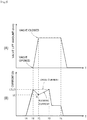
FIG. 3(A) is a time series graph showing the lift amount of thespill valve body 23 of theelectromagnetic spill valve 20, whereasFIG. 3(B) is a time series graph showing the flowing current (solid line) and the drive current (broken line) of theelectromagnetic spill valve 20. - As shown in
FIG. 3 , a time lag occurs in the actual behavior of thespill valve body 23 of theelectromagnetic spill valve 20 with respect to the flowing current of theelectromagnetic spill valve 20. - In the full automatic mode, the
current detector 55 detects current values IB, IC and predetermined times TB, TC, and TD and performs feedback control for correcting them to an optimum value. Specifically, the current waveform between TB and TC is fed back, and the same current waveform with the time axis of TC as the axis of symmetry is formed between TC and TD. - Specifically, between TB and TC, a counter electromotive force of the flowing current is generated as the drive current. Then, between the TC-TD, the current waveform is formed based on the fed back changes in the current value and the time between the TB-TC. At this time, with the current waveform having a V-shape, point A (point of valve closing) can be detected. It should be noted that TA and TE are values determined based on a map, according to the engine load.
- Here, when the fuel viscosity is high, the current waveform between TB-TC and the current waveform between TC-TD forms an asymmetrical V-shape with respect to the time axis of TC, as compared with a symmetrical V-shape formed when the fuel viscosity is low.
- In the manual mode, the current waveform of the drive current is formed only by a pre-set current values IB and IC, and predetermined times TB, TC, and TD. It should be noted that the pre-set current values IB and IC, and the predetermined times TB, TC, and TD are stored in the ECU50 in advance.
- The following describes a drive current control S100, with reference to
FIG. 4 . - It should be noted that
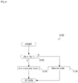
FIG. 4 is a flowchart showing a flow of the drive current control S100. - In the drive current control S100, the
ECU 50 switches the means for shaping the current waveform between the full automatic mode and the manual mode based on the fuel temperature TN. In step S110, theECU 50 determines whether the fuel temperature TN is higher than a predetermined temperature TN1. The process proceeds to step S120 if the fuel temperature TN is higher than the predetermined temperature TN1, whereas the process proceeds to step S130 if the fuel temperature TN is equal to or lower than the predetermined temperature TN1. - In step S120, the ECU50 shapes the current waveform of the drive current in the full automatic mode. In step S130, the ECU50 shapes the current waveform of the drive current in the manual mode. In the present embodiment, the predetermined temperature TN1 is 110 °C.
- An effect of the drive current control S100 is as follows.
- With the drive current control S100, the current waveform of the current flowing in the
electromagnetic spill valve 20 can be prevented from collapsing, even if the fuel viscosity is high. That is, when the fuel temperature TN is equal to or lower than the predetermined temperature TN1, the fuel viscosity of the fuel oil C is expected to be high. In this case, the means for shaping the current waveform of the drive current to the manual mode, and the current waveform of the current flowing in theelectromagnetic spill valve 20 can be prevented from collapsing. - The following describes a drive current control S200, with reference to
FIG. 5 . - It should be noted that
FIG. 5 is a flowchart showing a flow of the drive current control S200. - In the drive current control S200, the
ECU 50 switches the means for shaping the current waveform between the full automatic mode and the manual mode based on the engine speed NE. In step S210, theECU 50 determines whether the engine speed NE is higher than a predetermined engine speed NE1. The process proceeds to step S220 if the fuel engine speed NE is higher than the predetermined engine speed NE1, whereas the process proceeds to step S230 if the engine speed NE is equal to or lower than the predetermined engine speed NE1. - In step S220, the ECU50 shapes the current waveform of the drive current in the full automatic mode. In step S230, the ECU50 shapes the current waveform of the drive current in the manual mode. In the present embodiment, the predetermined engine speed NE1 is 720 rpm.
- An effect of the drive current control S200 is as follows.
- With the drive current control S200, the current waveform of the current flowing in the
electromagnetic spill valve 20 can be prevented from collapsing, even if the fuel viscosity is high. That is, when the engine speed NE is equal to or lower than the predetermined engine speed NE1, the fuel viscosity of the fuel oil C is expected to be high. In this case, the means for shaping the current waveform of the drive current to the manual mode, and the current waveform of the current flowing in theelectromagnetic spill valve 20 can be prevented from collapsing. - The following describes a drive current control S300, with reference to
FIG. 6 . - It should be noted that
FIG. 6 is a flowchart showing a flow of the drive current control S300. - In the drive current control S300, the
ECU 50 switches the means for shaping the current waveform between the full automatic mode and the manual mode based on the time elapsed after starting of the engine. In step S310, theECU 50 determines whether the diesel engine has been started. When the diesel engine is started, the process proceeds to step S320. - In step S320, the
ECU 50 determines whether 10 minutes have elapsed from the starting of the engine. The process proceeds to S330 if 10 minutes has elapsed from the starting of the engine, whereas the process proceeds to step S340 if 10 minutes has not yet elapsed from the start of the engine. In step S330, the ECU50 shapes the current waveform of the drive current in the full automatic mode. In step S340, the ECU50 shapes the current waveform of the drive current in the manual mode. - An effect of the drive current control S300 is as follows.
- With the drive current control S300, the current waveform of the current flowing in the
electromagnetic spill valve 20 can be prevented from collapsing, even if the fuel viscosity is high. That is, if the time elapsed from the starting of the diesel engine is less than 10 minutes, the fuel viscosity of the fuel oil C is expected to be high. In this case, the means for shaping the current waveform of the drive current to the manual mode, and the current waveform of the current flowing in theelectromagnetic spill valve 20 can be prevented from collapsing. - The present invention is applicable to a fuel injection pump.
-
- 20
- electromagnetic spill valve
- 23
- spill valve body
- 50
- ECU (control device)
- 100
- fuel injection pump
Claims (4)
- A fuel injection pump provided in a diesel engine, comprising:an electromagnetic spill valve configured to adjust a fuel injection amount by releasing pressurized fuel with opening/closing of a valve body; anda control device configured to form a current waveform of drive current of the electromagnetic spill valve,whereinthe control device, during a warm state, detects a valve-close timing of the electromagnetic spill valve, forms an optimum current waveform of drive current based on the detected valve-close timing, and applies drive current with thus formed optimum current waveform to the electromagnetic spill valve, whereas, during a cold state, applies only drive current with a pre-set current waveform to the electromagnetic spill valve.
- The fuel injection pump according to claim 1, comprising
a fuel temperature detector configured to detect a fuel temperature of fuel passing through the electromagnetic spill valve,
wherein the control device determines, as the warm state, if the fuel temperature equals to or higher than a predetermined temperature, and determines, as the cold state, if the fuel temperature is less than the predetermined temperature. - The fuel injection pump according to claim 1, wherein
the control device determines, as the warm state, if an engine speed at the time of starting the engine is equal to or higher than predetermined engine speed, and determines, as the cold state, if the engine speed at the time of starting the engine is lower than the predetermined engine speed. - The fuel injection pump according to claim 1, wherein
the control device determines, as the warm state, after elapse of a predetermined period from the starting of the engine, and determines, as the cold state, until the elapse of the predetermined period.
Applications Claiming Priority (2)
| Application Number | Priority Date | Filing Date | Title |
|---|---|---|---|
| JP2015225202A JP6464076B2 (en) | 2015-11-17 | 2015-11-17 | Fuel injection pump |
| PCT/JP2016/083418 WO2017086236A1 (en) | 2015-11-17 | 2016-11-10 | Fuel injection pump |
Publications (2)
| Publication Number | Publication Date |
|---|---|
| EP3379062A1 true EP3379062A1 (en) | 2018-09-26 |
| EP3379062A4 EP3379062A4 (en) | 2018-11-21 |
Family
ID=58718947
Family Applications (1)
| Application Number | Title | Priority Date | Filing Date |
|---|---|---|---|
| EP16866238.5A Withdrawn EP3379062A4 (en) | 2015-11-17 | 2016-11-10 | Fuel injection pump |
Country Status (6)
| Country | Link |
|---|---|
| US (1) | US10557437B2 (en) |
| EP (1) | EP3379062A4 (en) |
| JP (1) | JP6464076B2 (en) |
| KR (2) | KR102096197B1 (en) |
| CN (1) | CN108474309B (en) |
| WO (1) | WO2017086236A1 (en) |
Families Citing this family (6)
| Publication number | Priority date | Publication date | Assignee | Title |
|---|---|---|---|---|
| JP6464076B2 (en) * | 2015-11-17 | 2019-02-06 | ヤンマー株式会社 | Fuel injection pump |
| DE102016219956B3 (en) * | 2016-10-13 | 2017-08-17 | Continental Automotive Gmbh | Method for adjusting a damping flow of an intake valve of a motor vehicle high-pressure injection system, and control device, high-pressure injection system and motor vehicle |
| FR3083828B1 (en) * | 2018-07-13 | 2020-06-12 | Continental Automotive France | METHOD FOR DIAGNOSING A DIGITAL VALVE FOR CONTROLLING THE FLOW OF A HIGH PRESSURE FUEL INJECTION PUMP |
| US11230990B2 (en) * | 2019-11-11 | 2022-01-25 | Caterpillar Inc. | Method and system for valve movement detection |
| US11293370B1 (en) * | 2020-11-20 | 2022-04-05 | Caterpillar Inc. | Method and system for valve position monitoring |
| US11313338B1 (en) * | 2020-11-20 | 2022-04-26 | Caterpillar Inc. | Method and system for monitoring injector valves |
Family Cites Families (26)
| Publication number | Priority date | Publication date | Assignee | Title |
|---|---|---|---|---|
| JPH063164B2 (en) | 1985-02-25 | 1994-01-12 | トヨタ自動車株式会社 | Fuel injection timing control method for diesel engine |
| JP3245718B2 (en) * | 1992-03-26 | 2002-01-15 | 株式会社ボッシュオートモーティブシステム | Fuel injection device |
| DE69320829T2 (en) * | 1992-03-26 | 1999-01-21 | Zexel Corp | Fuel injector |
| JPH063164A (en) | 1992-06-18 | 1994-01-11 | Ricoh Co Ltd | Rotational position detector |
| ATE215178T1 (en) * | 1994-05-06 | 2002-04-15 | Cummins Engine Co Inc | METHOD AND DEVICE FOR ELECTRONIC CONTROL OF A STORAGE FUEL SYSTEM |
| JPH08232686A (en) | 1995-02-23 | 1996-09-10 | Nippondenso Co Ltd | Method and device for controlling fuel injection pump |
| US6766241B2 (en) * | 2001-12-26 | 2004-07-20 | Deere & Company | Fuel injection control system |
| JP3855861B2 (en) * | 2002-06-28 | 2006-12-13 | トヨタ自動車株式会社 | High pressure fuel supply device for internal combustion engine |
| JP4338742B2 (en) * | 2007-03-09 | 2009-10-07 | 三菱電機株式会社 | High pressure fuel pump control device for internal combustion engine |
| DE102007035316B4 (en) * | 2007-07-27 | 2019-12-24 | Robert Bosch Gmbh | Method for controlling a solenoid valve of a quantity control in an internal combustion engine |
| JP4587133B2 (en) * | 2008-06-04 | 2010-11-24 | 株式会社デンソー | Fuel supply device |
| DE102010022536A1 (en) * | 2010-06-02 | 2011-12-08 | Continental Automotive Gmbh | Method and device for controlling a valve |
| DE102010039832A1 (en) * | 2010-08-26 | 2012-03-01 | Continental Automotive Gmbh | Method and device for detecting reaching a closing point of a hydraulic valve |
| JP5502806B2 (en) * | 2011-06-13 | 2014-05-28 | 株式会社日本自動車部品総合研究所 | Solenoid valve and high-pressure pump using the same |
| JP6221828B2 (en) * | 2013-08-02 | 2017-11-01 | 株式会社デンソー | High pressure pump control device |
| JP6244723B2 (en) * | 2013-08-02 | 2017-12-13 | 株式会社デンソー | High pressure pump control device |
| JP6130280B2 (en) * | 2013-09-25 | 2017-05-17 | 日立オートモティブシステムズ株式会社 | Drive device for fuel injection device |
| JP6511266B2 (en) * | 2014-12-25 | 2019-05-15 | 日立オートモティブシステムズ株式会社 | Fuel injection valve control device |
| DE102015203415B4 (en) * | 2015-02-26 | 2020-11-26 | Schaeffler Technologies AG & Co. KG | Procedure for the simulation of extreme or defective solenoid valves to demonstrate the failure effects and error detection for the certification of a vehicle diagnostic system |
| EP3321499A4 (en) * | 2015-07-09 | 2019-03-06 | Hitachi Automotive Systems, Ltd. | Control device for fuel injection device |
| JP6464972B2 (en) * | 2015-09-24 | 2019-02-06 | 株式会社デンソー | High pressure pump controller |
| US10428970B2 (en) * | 2015-10-20 | 2019-10-01 | GM Global Technology Operations LLC | Method of operating a digital inlet valve |
| JP6464076B2 (en) * | 2015-11-17 | 2019-02-06 | ヤンマー株式会社 | Fuel injection pump |
| US10234496B2 (en) * | 2016-02-16 | 2019-03-19 | Woodward, Inc. | Detection of valve open time for solenoid operated fuel injectors |
| KR101877299B1 (en) * | 2016-04-07 | 2018-07-11 | (주)모토닉 | Control apparatus and method of flow control valve for high pressure fuel pump |
| US10401398B2 (en) * | 2017-03-03 | 2019-09-03 | Woodward, Inc. | Fingerprinting of fluid injection devices |
-
2015
- 2015-11-17 JP JP2015225202A patent/JP6464076B2/en active Active
-
2016
- 2016-11-10 KR KR1020187016835A patent/KR102096197B1/en active IP Right Grant
- 2016-11-10 US US15/776,934 patent/US10557437B2/en not_active Expired - Fee Related
- 2016-11-10 EP EP16866238.5A patent/EP3379062A4/en not_active Withdrawn
- 2016-11-10 WO PCT/JP2016/083418 patent/WO2017086236A1/en active Application Filing
- 2016-11-10 KR KR1020207008555A patent/KR102443620B1/en active IP Right Grant
- 2016-11-10 CN CN201680062686.4A patent/CN108474309B/en not_active Expired - Fee Related
Also Published As
| Publication number | Publication date |
|---|---|
| KR20200034840A (en) | 2020-03-31 |
| KR102443620B1 (en) | 2022-09-14 |
| KR20180075682A (en) | 2018-07-04 |
| JP2017089602A (en) | 2017-05-25 |
| EP3379062A4 (en) | 2018-11-21 |
| CN108474309B (en) | 2021-07-06 |
| US10557437B2 (en) | 2020-02-11 |
| JP6464076B2 (en) | 2019-02-06 |
| CN108474309A (en) | 2018-08-31 |
| US20180328308A1 (en) | 2018-11-15 |
| WO2017086236A1 (en) | 2017-05-26 |
| KR102096197B1 (en) | 2020-04-01 |
Similar Documents
| Publication | Publication Date | Title |
|---|---|---|
| EP3379062A1 (en) | Fuel injection pump | |
| US9429097B2 (en) | Direct injection pump control | |
| US9200580B2 (en) | Method and device for operating an injection valve | |
| JP2005307885A (en) | Common rail type fuel injection device | |
| JP6005274B2 (en) | Operation method of switching element of valve device | |
| JP2008223528A (en) | High-pressure fuel pump control device of internal combustion engine | |
| CN105593507A (en) | Injection valve and method for operation of injection valve | |
| JP2005140046A (en) | Injection amount controller for diesel engine | |
| CN105508068B (en) | Method for predetermining the current in a solenoid valve | |
| JP2015081538A (en) | Pump control device | |
| JP5856384B2 (en) | Fuel supply system and fuel injection control device | |
| JP2009138593A (en) | Accumulating type fuel injection device | |
| KR20160011585A (en) | Method for adapting fuel pressure in low pressure region of fuel direct injection system | |
| CN109154243B (en) | Fuel injection valve energization control method and common rail type fuel injection control device | |
| CN105317575B (en) | Method for controlling multiple injections in a fuel injection system, in particular of an internal combustion engine | |
| JP6303944B2 (en) | Fuel injection control device | |
| US9976505B2 (en) | Method for operating an injector of an injection system of an internal combustion engine | |
| JP2015206268A (en) | Correction control method for forced fuel transfer and common rail-type fuel injection control device | |
| JP6327166B2 (en) | Fuel supply pump controller | |
| JP5532885B2 (en) | Fuel injection device | |
| JP4321495B2 (en) | Accumulated fuel injection system | |
| JP2018123789A (en) | Internal combustion engine fuel injection device | |
| JP2020060166A (en) | Fuel injection control method and fuel injection control device | |
| JP2017145756A (en) | Internal combustion engine and fuel injection control method for internal combustion engine | |
| JP2007132215A (en) | Fuel injection device |
Legal Events
| Date | Code | Title | Description |
|---|---|---|---|
| STAA | Information on the status of an ep patent application or granted ep patent |
Free format text: STATUS: THE INTERNATIONAL PUBLICATION HAS BEEN MADE |
|
| PUAI | Public reference made under article 153(3) epc to a published international application that has entered the european phase |
Free format text: ORIGINAL CODE: 0009012 |
|
| STAA | Information on the status of an ep patent application or granted ep patent |
Free format text: STATUS: REQUEST FOR EXAMINATION WAS MADE |
|
| 17P | Request for examination filed |
Effective date: 20180618 |
|
| AK | Designated contracting states |
Kind code of ref document: A1 Designated state(s): AL AT BE BG CH CY CZ DE DK EE ES FI FR GB GR HR HU IE IS IT LI LT LU LV MC MK MT NL NO PL PT RO RS SE SI SK SM TR |
|
| AX | Request for extension of the european patent |
Extension state: BA ME |
|
| RIN1 | Information on inventor provided before grant (corrected) |
Inventor name: MACHIYAMA, HIROYUKI Inventor name: IWANO, RYOTA Inventor name: OKAMOTO, RYOSUKE Inventor name: HARA, KOSUKE Inventor name: HIROYA, SATOSHI |
|
| A4 | Supplementary search report drawn up and despatched |
Effective date: 20181023 |
|
| RIC1 | Information provided on ipc code assigned before grant |
Ipc: F02D 41/04 20060101ALI20181017BHEP Ipc: F02M 59/20 20060101ALI20181017BHEP Ipc: F02M 59/46 20060101ALN20181017BHEP Ipc: F02D 41/20 20060101AFI20181017BHEP Ipc: F02D 41/40 20060101ALI20181017BHEP Ipc: F02D 41/06 20060101ALI20181017BHEP Ipc: F02D 41/02 20060101ALI20181017BHEP |
|
| DAV | Request for validation of the european patent (deleted) | ||
| DAX | Request for extension of the european patent (deleted) | ||
| GRAP | Despatch of communication of intention to grant a patent |
Free format text: ORIGINAL CODE: EPIDOSNIGR1 |
|
| STAA | Information on the status of an ep patent application or granted ep patent |
Free format text: STATUS: GRANT OF PATENT IS INTENDED |
|
| RIC1 | Information provided on ipc code assigned before grant |
Ipc: F02D 41/40 20060101ALI20190930BHEP Ipc: F02D 41/02 20060101ALI20190930BHEP Ipc: F02D 41/06 20060101ALI20190930BHEP Ipc: F02D 41/04 20060101ALI20190930BHEP Ipc: F02M 59/20 20060101ALI20190930BHEP Ipc: F02M 59/46 20060101ALN20190930BHEP Ipc: F02D 41/20 20060101AFI20190930BHEP |
|
| INTG | Intention to grant announced |
Effective date: 20191018 |
|
| STAA | Information on the status of an ep patent application or granted ep patent |
Free format text: STATUS: THE APPLICATION IS DEEMED TO BE WITHDRAWN |
|
| 18D | Application deemed to be withdrawn |
Effective date: 20200229 |