EP3379009A1 - Arrangement for stopping a door for opening and closing a space, such as the cargo space of a vehicle, especially in the open position thereof - Google Patents
Arrangement for stopping a door for opening and closing a space, such as the cargo space of a vehicle, especially in the open position thereof Download PDFInfo
- Publication number
- EP3379009A1 EP3379009A1 EP18162433.9A EP18162433A EP3379009A1 EP 3379009 A1 EP3379009 A1 EP 3379009A1 EP 18162433 A EP18162433 A EP 18162433A EP 3379009 A1 EP3379009 A1 EP 3379009A1
- Authority
- EP
- European Patent Office
- Prior art keywords
- lever
- handle
- stop
- door
- fixed base
- Prior art date
- Legal status (The legal status is an assumption and is not a legal conclusion. Google has not performed a legal analysis and makes no representation as to the accuracy of the status listed.)
- Granted
Links
- 230000006835 compression Effects 0.000 claims description 6
- 238000007906 compression Methods 0.000 claims description 6
- 230000000694 effects Effects 0.000 claims description 4
- 230000000903 blocking effect Effects 0.000 description 1
Images


Classifications
-
- E—FIXED CONSTRUCTIONS
- E05—LOCKS; KEYS; WINDOW OR DOOR FITTINGS; SAFES
- E05C—BOLTS OR FASTENING DEVICES FOR WINGS, SPECIALLY FOR DOORS OR WINDOWS
- E05C17/00—Devices for holding wings open; Devices for limiting opening of wings or for holding wings open by a movable member extending between frame and wing; Braking devices, stops or buffers, combined therewith
- E05C17/02—Devices for holding wings open; Devices for limiting opening of wings or for holding wings open by a movable member extending between frame and wing; Braking devices, stops or buffers, combined therewith by mechanical means
- E05C17/46—Devices for holding wings open; Devices for limiting opening of wings or for holding wings open by a movable member extending between frame and wing; Braking devices, stops or buffers, combined therewith by mechanical means in which the wing or a member fixed thereon is engaged by a movable fastening member in a fixed position; in which a movable fastening member mounted on the wing engages a stationary member
- E05C17/50—Devices for holding wings open; Devices for limiting opening of wings or for holding wings open by a movable member extending between frame and wing; Braking devices, stops or buffers, combined therewith by mechanical means in which the wing or a member fixed thereon is engaged by a movable fastening member in a fixed position; in which a movable fastening member mounted on the wing engages a stationary member comprising a single pivoted securing member
-
- E—FIXED CONSTRUCTIONS
- E05—LOCKS; KEYS; WINDOW OR DOOR FITTINGS; SAFES
- E05B—LOCKS; ACCESSORIES THEREFOR; HANDCUFFS
- E05B15/00—Other details of locks; Parts for engagement by bolts of fastening devices
- E05B15/04—Spring arrangements in locks
- E05B2015/0403—Wound springs
- E05B2015/0427—Wound springs curved, e.g. toroidal
-
- E—FIXED CONSTRUCTIONS
- E05—LOCKS; KEYS; WINDOW OR DOOR FITTINGS; SAFES
- E05B—LOCKS; ACCESSORIES THEREFOR; HANDCUFFS
- E05B63/00—Locks or fastenings with special structural characteristics
- E05B63/0056—Locks with adjustable or exchangeable lock parts
-
- E—FIXED CONSTRUCTIONS
- E05—LOCKS; KEYS; WINDOW OR DOOR FITTINGS; SAFES
- E05B—LOCKS; ACCESSORIES THEREFOR; HANDCUFFS
- E05B83/00—Vehicle locks specially adapted for particular types of wing or vehicle
- E05B83/02—Locks for railway freight-cars, freight containers or the like; Locks for the cargo compartments of commercial lorries, trucks or vans
- E05B83/08—Locks for railway freight-cars, freight containers or the like; Locks for the cargo compartments of commercial lorries, trucks or vans with elongated bars for actuating the fastening means
- E05B83/10—Rotary bars
Definitions
- the invention relates to an arrangement for stopping an opening and closing door of a space such as the loading space of a vehicle, in particular in its open position, of the type comprising a fixed mounted base part. on the support structure of the door, a stop lever pivotally mounted on the fixed base between a rest position and a stop position of the door in its open position, a handle device for actuating the pivoting of the lever and lever return means in its rest and stop positions.
- the object of the invention is to propose a simpler and more compact arrangement.
- the arrangement according to the invention is characterized in that it comprises means for locking the handle on the fixed base when the stop lever is in its position of stopping the door.
- the handle comprises a lockable hook on a spout of the fixed base, under the effect of spring means interposed between the handle and the lever, thanks to a relative pivoting movement between the handle and the lever, and in that the handle and the lever are integral in rotation when pivoting between the stop and rest positions of the lever
- the stop lever is movable by the handle towards its stop position against return means and from its stop position to its rest position by these return means.
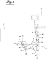
- the door stop arrangement according to the invention is intended in particular, but not exclusively, to equip the crates of transport cars, as is schematically indicated in FIGS. figures 3 and 4 on which the references 3, 4 and 5 respectively designate the vehicle body, the door and the bolt of the espagnolette.
- the door stop arrangement 1 essentially comprises a fixed base portion 10 adapted, in the case shown, to be fixed under the body 3 of the vehicle, a stop lever 14 which is mounted on the fixed part 10, pivoting about an axis 12 between the rest position removed under the body and its door stop position, that is to say blocking the door 4 in its open position , in accordance with the figure 4 as well as an actuating handle 16 of the lever.
- the arrangement 1 is essentially characterized by the fact that the stop lever 14 is pivotally mounted about the axis 14 of the fixing base 10 between its rest and stop positions, against spring means 18, that the handle 16 comprises a hook-shaped element 20 by which it is lockable on the fixed base 10 by engaging behind a spout 22 of the base when the lever is in its stop position, and that for this purpose the handle 16 is held on the lever 14 so as to be integral in rotation with the latter in the direction F1 of pivoting towards the stop position of the door, then is able to pivot on the lever, around an axis 24, against a return spring 26 to ensure the engagement of the hook 20 behind the spout 22.
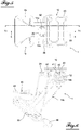
- the stop lever 14 is composed of two lateral cheek pieces 14a, 14b and a central piece 14c sandwiched between the cheeks 14a, 14b . More specifically, each cheek has the general shape of a T pivotally mounted on the fixed base 10 about an axis 12a, 12b by the free end of its leg 30, while the central piece 14c is mounted between the two branches 33 of the cheeks.
- the central piece 14c has a fixing portion 35 by which it is mounted between the leg portions 33 of the cheeks, in a positionally adjustable manner in the axial direction thereof as is apparent from FIG.
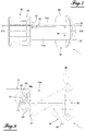
- the return spring means 18 of the lever in its rest position are formed by two compression springs 18a, 18b, each associated with a cheek 14a, 14b. Each spring is mounted in a circular casing 39 and is supported by one end on a stop face 41 integral with the base and an abutment surface 40 integral with the cheek ( figure 4 ). As shown in particular by the comparison of figures 6 and 8 , the pivoting of the lever 14 towards its door stop position causes compression of the springs 18a, 18b in their circular housing 39.
- the figure 9 also shows that the fixing base 10 has a sole-shaped portion 43 and a perpendicularly projecting portion 44 which carries at its free end the mouth 22 of the handle 16.
- This handle 16 comprises a pivot actuating portion 45 of the lever 14 and a portion 46 which terminates in the locking hook.
- the handle comprises a third support portion 47 by which it is mounted on the lever 14, precisely on both cheeks, with the interposition of the return spring 26 between the handle and the cheeks 14a, 14b which each engage with a pin 24a 24b in a bearing element 50 of the handle.
- Each cheek is further provided with a projecting element 52a, 52b on which bears one end of the spring 26 whose central portion is supported by the bearing 50.
- the lever 14 To stop the door 4 in its open position, the lever 14 is pivoted from its rest position to the figure 3 using the handle 16 in its door stop position of the figure 4 . In this door stop position, the lever bears on its head portion 36 against the espagnolette bolt 5 of the door. The lever is locked in this position by locking the handle 16 on the fixed base 10 through the engagement of the hook 20 behind the spout 22. More specifically, by pulling the handle 16 in the direction of the arrow F1, it causes the pivoting of the stop lever 14 in the same direction, the rounding of the profile of the handle at the hook 20 sliding along the rounded profile of the spout 22 of the base, as shown in FIG. figure 10B . When the hook passes over the spout and the handle is released, the hook engages behind the spout under the effect of the torsion spring 26 which pivots the handle about the spindle 24 relative to the lever for this purpose. 14.
Landscapes
- Engineering & Computer Science (AREA)
- Mechanical Engineering (AREA)
- Lock And Its Accessories (AREA)
Abstract
L'invention concerne un agencement d'arrêt d'une porte (4) d'ouverture et de fermeture d'un espace tel que l'espace de chargement d'un véhicule, notamment dans sa position ouverte, du type comprenant une partie de base fixe (10) montée sur la structure de support de la porte (4), un levier d'arrêt (14) monté pivotant sur la base fixe (10) entre une position de repos et une position d'arrêt de la porte (4) dans sa position ouverte, une poignée d'actionnement (16) du pivotement du levier (14) et des moyens de rappel (18) du levier (14) dans cette position de repos et d'arrêt, caractérisé en ce qu'il comprend des moyens de verrouillage (20, 22) de la poignée (16) sur la base fixe (10) lorsque le levier d'arrêt (14) est dans sa position d'arrêt de la porte (4). L'invention est utilisable pour des véhicules de transport.The invention relates to an arrangement for stopping a door (4) for opening and closing a space such that the loading space of a vehicle, in particular in its open position, of the type comprising a portion of fixed base (10) mounted on the support structure of the door (4), a stop lever (14) pivotally mounted on the fixed base (10) between a rest position and a stop position of the door ( 4) in its open position, an actuating handle (16) for pivoting the lever (14) and return means (18) for the lever (14) in this rest and stop position, characterized in that it comprises locking means (20, 22) of the handle (16) on the fixed base (10) when the stop lever (14) is in its stop position of the door (4). The invention is usable for transport vehicles.
Description
L'invention concerne un agencement d'arrêt d'une porte d'ouverture et de fermeture d'un espace tel que l'espace de chargement d'un véhicule, notamment dans sa position ouverte, du type comprenant une partie de base montée fixe sur la structure de support de la porte, un levier d'arrêt monté pivotant sur la base fixe entre une position de repos et une position d'arrêt de la porte dans sa position ouverte, un dispositif de poignée d'actionnement du pivotement du levier et des moyens de rappel du levier dans ses positions de repos et d'arrêt.The invention relates to an arrangement for stopping an opening and closing door of a space such as the loading space of a vehicle, in particular in its open position, of the type comprising a fixed mounted base part. on the support structure of the door, a stop lever pivotally mounted on the fixed base between a rest position and a stop position of the door in its open position, a handle device for actuating the pivoting of the lever and lever return means in its rest and stop positions.
Un agencement de ce type est déjà connu par le document
L'invention a pour but de proposer un agencement plus simple et plus compact.The object of the invention is to propose a simpler and more compact arrangement.
Pour atteindre ce but, l'agencement selon l'invention est caractérisé en ce qu'il comprend des moyens de verrouillage de la poignée sur la base fixe lorsque le levier d'arrêt est dans sa position d'arrêt de la porte.To achieve this purpose, the arrangement according to the invention is characterized in that it comprises means for locking the handle on the fixed base when the stop lever is in its position of stopping the door.
Selon une caractéristique de l'invention, la poignée comprend un crochet verrouillable sur un bec de la base fixe, sous l'effet de moyens de ressort interposés entre la poignée et le levier, grâce à un mouvement de pivotement relatif entre la poignée et le levier, et en ce que la poignée et le levier sont solidaires en rotation lors du pivotement entre les positions d'arrêt et de repos du levierAccording to a feature of the invention, the handle comprises a lockable hook on a spout of the fixed base, under the effect of spring means interposed between the handle and the lever, thanks to a relative pivoting movement between the handle and the lever, and in that the handle and the lever are integral in rotation when pivoting between the stop and rest positions of the lever
Selon une autre caractéristique de l'invention, le levier d'arrêt est déplaçable par la poignée vers sa position d'arrêt à l'encontre de moyens de rappel et de sa position d'arrêt vers sa position de repos par ces moyens de rappel.According to another characteristic of the invention, the stop lever is movable by the handle towards its stop position against return means and from its stop position to its rest position by these return means. .
L'invention sera mieux comprise, et d'autres buts, caractéristiques, détails et avantages de celle-ci apparaîtront plus clairement dans la description explicative qui va suivre faite en référence aux dessins annexés donnés uniquement à titre d'exemple illustrant un mode de réalisation de l'invention et dans lesquels :
- les
figures 1 et 2 sont des vues en perspective d'un agencement d'arrêt de porte selon l'invention, montrant celui-ci respectivement dans sa position de repos et sa position d'arrêt de porte ; - les
figures 3 et4 sont des vues latérales de l'agencement selon l'invention, monté sur une caisse d'un véhicule, dans ses positions respectivement de repos et d'arrêt de porte ; - la
figure 5 est une vue en direction de la flèche V de lafigure 3 ; - la
figure 6 est une vue en coupe le long de la ligne VI-VI de lafigure 5 ; - la
figure 7 est une vue en direction de la flèche VII de lafigure 4 ; - la
figure 8 est une vue en coupe le long de la ligne VIII-VIII de lafigure 7 ; - la
figure 9 est une vue en perspective et explosée de l'agencement selon l'invention ; - les
figures 10A, 10B et 10C sont des vues en coupe le long de la ligne X-X de lafigure 5 et montrent l'agencement dans trois phases différentes de son fonctionnement.
- the
Figures 1 and 2 are perspective views of a door stop arrangement according to the invention, showing it respectively in its rest position and its door stop position; - the
figures 3 and4 are side views of the arrangement according to the invention, mounted on a body of a vehicle, in its positions of respectively rest and stop door; - the
figure 5 is a view towards the arrow V of thefigure 3 ; - the
figure 6 is a sectional view along the line VI-VI of thefigure 5 ; - the
figure 7 is a view towards the arrow VII of thefigure 4 ; - the
figure 8 is a sectional view along line VIII-VIII of thefigure 7 ; - the
figure 9 is a perspective and exploded view of the arrangement according to the invention; - the
Figures 10A, 10B and 10C are sectional views along line XX of thefigure 5 and show the arrangement in three different phases of its operation.
L'agencement d'arrêt de porte selon l'invention, désigné de façon générale par la référence 1, est destiné notamment, mais non pas exclusivement, à équiper des caisses de voitures de transport, comme cela indique schématiquement les
Comme il ressort des figures, l'agencement d'arrêt de porte 1 comporte essentiellement une partie de base fixe 10 adaptée, dans le cas d'exemple représenté, à être fixé sous la caisse 3 du véhicule, un levier d'arrêt 14 qui est monté sur la partie fixe 10, pivotant autour d'un axe 12 entre la position de repos retirée sous la caisse et sa position d'arrêt de porte, c'est-à-dire de blocage de la porte 4 dans sa position ouverte, conformément à la
L'agencement 1 est caractérisé essentiellement par le fait que le levier d'arrêt 14 est monté pivotant autour de l'axe 14 de la base de fixation 10 entre ses positions de repos et d'arrêt, à l'encontre de moyens de ressort de rappel 18, que la poignée 16 comporte un élément en forme d'un crochet 20 par lequel il est verrouillable sur la base fixe 10 en venant en prise derrière un bec 22 de la base lorsque le levier est dans sa position d'arrêt, et qu'à cette fin la poignée 16 est maintenue sur le levier 14 de façon à être solidaire en rotation de ce dernier dans la direction F1 de pivotement vers la position d'arrêt de la porte, puis soit susceptible de pivoter sur le levier, autour d'un axe 24, à l'encontre d'un ressort de rappel 26 pour assurer l'engagement du crochet 20 derrière le bec 22.The
Pour déverrouiller la poignée et ainsi permettre le retour du levier dans sa position de repos de la
On décrira ci-après, de façon détaillée la structure de l'agencement d'arrêt de porte 1, telle qu'elle est illustrée sur les figures, en sachant qu'il s'agit seulement d'un exemple de mise en oeuvre de l'invention non limitative.The structure of the
En se référant notamment à la
La
Cette poignée 16 comprend une partie 45 d'actionnement en pivotement du levier 14 et une partie 46 qui se termine par le crochet de verrouillage. La poignée comprend une troisième partie de support 47 par laquelle elle est montée sur le levier 14, précisément sur les deux joues, avec interposition du ressort de rappel 26 entre la poignée et les joues 14a, 14b qui s'engageant chacune par un tourillon 24a, 24b dans un élément de palier 50 de la poignée. Chaque joue est en outre pourvue d'un élément en saillie 52a, 52b sur lequel prend appui une extrémité du ressort 26 dont la partie centrale est supportée par le palier 50.This
Le fonctionnement de l'agencement d'arrêt de porte selon l'invention ressort déjà de la description qui précède. Pour arrêter la porte 4 dans sa position ouverte, on fait pivoter le levier 14 de sa position de repos de la
Pour libérer la porte on déverrouille la poignée 16 de la base fixe en poussant la poignée 16 dans la direction de la flèche F2 jusqu'à ce que le crochet soit dégagé du bec, ce qui permet au levier de revenir, avec la poignée, dans sa position de repos sous l'effet du ressort de compression 18.To release the door unlocking the
Comme il a été précisé plus haut, la structure de l'agencement tel qu'il est représenté sur les figures n'a été donnée qu'à titre d'exemple et les pièces essentielles, à savoir la base fixe 10, le levier 14 et la poignée 16 peuvent être réalisés de toute autre façon, à condition de respecter les fonctions de ces pièces, qui viennent d'être évoquées.As has been stated above, the structure of the arrangement as shown in the figures has been given by way of example and the essential parts, namely the
Claims (5)
Applications Claiming Priority (1)
| Application Number | Priority Date | Filing Date | Title |
|---|---|---|---|
| FR1752356A FR3064215B1 (en) | 2017-03-22 | 2017-03-22 | ARRANGEMENT OF STOPPING A DOOR FOR OPENING AND CLOSING A SPACE SUCH AS THE LOADING SPACE OF A VEHICLE, ESPECIALLY IN ITS OPEN POSITION |
Publications (2)
| Publication Number | Publication Date |
|---|---|
| EP3379009A1 true EP3379009A1 (en) | 2018-09-26 |
| EP3379009B1 EP3379009B1 (en) | 2020-07-08 |
Family
ID=58993056
Family Applications (1)
| Application Number | Title | Priority Date | Filing Date |
|---|---|---|---|
| EP18162433.9A Active EP3379009B1 (en) | 2017-03-22 | 2018-03-16 | Arrangement for stopping a door for opening and closing a space, such as the cargo space of a vehicle, in the open position thereof |
Country Status (3)
| Country | Link |
|---|---|
| EP (1) | EP3379009B1 (en) |
| ES (1) | ES2824923T3 (en) |
| FR (1) | FR3064215B1 (en) |
Citations (6)
| Publication number | Priority date | Publication date | Assignee | Title |
|---|---|---|---|---|
| FR2496746A1 (en) * | 1980-12-19 | 1982-06-25 | Esinplast | Holder for window shutter - comprises U=shaped trip which pivots about support to retain edge of shutter between arms |
| EP0119413A2 (en) * | 1983-03-17 | 1984-09-26 | Mayer & Co. | Automatic clamping means, in particular for window shutters |
| EP0823524A2 (en) * | 1996-08-09 | 1998-02-11 | Esinplast di Cirilli Alessandro & C.-S.N.C. | Automatic window shutter stop |
| FR2795762A1 (en) * | 1999-06-30 | 2001-01-05 | Tordo Belgrano Sa | Open prop for building window has pivot mounting to allow one hundred and eighty degree pivoting of arm |
| EP2878521A1 (en) * | 2013-11-18 | 2015-06-03 | Lamberet | Device for retaining an openable body section of a vehicle |
| US20150159429A1 (en) * | 2013-12-10 | 2015-06-11 | David Lund | Sliding fenestration control device |
-
2017
- 2017-03-22 FR FR1752356A patent/FR3064215B1/en active Active
-
2018
- 2018-03-16 ES ES18162433T patent/ES2824923T3/en active Active
- 2018-03-16 EP EP18162433.9A patent/EP3379009B1/en active Active
Patent Citations (6)
| Publication number | Priority date | Publication date | Assignee | Title |
|---|---|---|---|---|
| FR2496746A1 (en) * | 1980-12-19 | 1982-06-25 | Esinplast | Holder for window shutter - comprises U=shaped trip which pivots about support to retain edge of shutter between arms |
| EP0119413A2 (en) * | 1983-03-17 | 1984-09-26 | Mayer & Co. | Automatic clamping means, in particular for window shutters |
| EP0823524A2 (en) * | 1996-08-09 | 1998-02-11 | Esinplast di Cirilli Alessandro & C.-S.N.C. | Automatic window shutter stop |
| FR2795762A1 (en) * | 1999-06-30 | 2001-01-05 | Tordo Belgrano Sa | Open prop for building window has pivot mounting to allow one hundred and eighty degree pivoting of arm |
| EP2878521A1 (en) * | 2013-11-18 | 2015-06-03 | Lamberet | Device for retaining an openable body section of a vehicle |
| US20150159429A1 (en) * | 2013-12-10 | 2015-06-11 | David Lund | Sliding fenestration control device |
Also Published As
| Publication number | Publication date |
|---|---|
| FR3064215A1 (en) | 2018-09-28 |
| ES2824923T3 (en) | 2021-05-13 |
| FR3064215B1 (en) | 2021-08-06 |
| EP3379009B1 (en) | 2020-07-08 |
Similar Documents
| Publication | Publication Date | Title |
|---|---|---|
| EP1644604B1 (en) | Latch for joining two panels of an airplane structure | |
| FR2940673A1 (en) | SECURITY HOOK | |
| FR2715766A1 (en) | Holding lock provided with a locking mechanism. | |
| FR2821028A1 (en) | SEAT DEVICE COMPRISING A FOLDING BACK | |
| FR2975052A1 (en) | JOINT ASSEMBLY FOR VEHICLE SEAT AND VEHICLE SEAT COMPRISING THE JOINT ASSEMBLY | |
| FR2753419A1 (en) | Device for visible locking of vehicle seat foldable back | |
| EP3718429B1 (en) | Insert for a watch strap | |
| EP1894770A1 (en) | Automotive seat for a child, pivotable between a use position and at least one access position, having a hook with dual locking mode | |
| EP2179119B1 (en) | Locking device comprising a telescopic connecting rod equipped with return means | |
| FR3050919A1 (en) | KITCHEN USTENSILE WITH REMOVABLE HANDLE | |
| EP3379009B1 (en) | Arrangement for stopping a door for opening and closing a space, such as the cargo space of a vehicle, in the open position thereof | |
| EP1561888B1 (en) | Housing of an espagnolette lock having a rod abutment member | |
| FR2921956A1 (en) | "HANDLE SYSTEM INCLUDING CREMONE, INTENDED TO BE IMPLANTED ON AN EXTERNAL DOOR SIDE, SUCH AS A REFRIGERATED TRUCK DOOR". | |
| EP2137026A2 (en) | Seat for automobile convertible into child seat with the back facing road and related automobile | |
| FR2697566A1 (en) | Lock with pivoting catch actuated by key-operated barrel mechanism - has transmission components engaging between barrel and catch, cooperating with movable portion of catch biassed by spring against lock clip | |
| FR3040581A1 (en) | RECEIVING BAY OF ELECTRONIC EQUIPMENT, FOR EXAMPLE AVIONICS | |
| FR3087418A1 (en) | SYSTEM FOR FIXING A SEAT | |
| CH716060A2 (en) | Insert for a strand of a watch strap. | |
| FR3069217A1 (en) | GLOVES BOX | |
| EP3392086A1 (en) | Arrangement of a securing ring on a supporting structure such as the bank edge or a floor, in particular for loading a transport vehicle | |
| EP2556974A1 (en) | Hitch arrangement for a tow vehicle, comprising a hook body for receiving a coupling member of a towed vehicle | |
| EP1034717B1 (en) | Key holder comprising a case and a key | |
| FR2900880A1 (en) | Backrest locking device for motor vehicle, has control unit activating locking unit and integrating with coupling part of button, where control unit presents coupling part conformed to be coupled with coupling part of button | |
| FR2491901A3 (en) | Safety lifting hook for use with block and tackle - has pivoted closing link pivoted to part of main hooking body to lock it shut | |
| EP0784251A1 (en) | Device for connecting a band to a watch case |
Legal Events
| Date | Code | Title | Description |
|---|---|---|---|
| PUAI | Public reference made under article 153(3) epc to a published international application that has entered the european phase |
Free format text: ORIGINAL CODE: 0009012 |
|
| STAA | Information on the status of an ep patent application or granted ep patent |
Free format text: STATUS: THE APPLICATION HAS BEEN PUBLISHED |
|
| AK | Designated contracting states |
Kind code of ref document: A1 Designated state(s): AL AT BE BG CH CY CZ DE DK EE ES FI FR GB GR HR HU IE IS IT LI LT LU LV MC MK MT NL NO PL PT RO RS SE SI SK SM TR |
|
| AX | Request for extension of the european patent |
Extension state: BA ME |
|
| STAA | Information on the status of an ep patent application or granted ep patent |
Free format text: STATUS: REQUEST FOR EXAMINATION WAS MADE |
|
| 17P | Request for examination filed |
Effective date: 20181026 |
|
| RBV | Designated contracting states (corrected) |
Designated state(s): AL AT BE BG CH CY CZ DE DK EE ES FI FR GB GR HR HU IE IS IT LI LT LU LV MC MK MT NL NO PL PT RO RS SE SI SK SM TR |
|
| GRAP | Despatch of communication of intention to grant a patent |
Free format text: ORIGINAL CODE: EPIDOSNIGR1 |
|
| STAA | Information on the status of an ep patent application or granted ep patent |
Free format text: STATUS: GRANT OF PATENT IS INTENDED |
|
| RIC1 | Information provided on ipc code assigned before grant |
Ipc: E05B 83/10 20140101ALN20191218BHEP Ipc: E05C 17/50 20060101AFI20191218BHEP Ipc: E05B 15/04 20060101ALN20191218BHEP |
|
| INTG | Intention to grant announced |
Effective date: 20200120 |
|
| GRAS | Grant fee paid |
Free format text: ORIGINAL CODE: EPIDOSNIGR3 |
|
| GRAA | (expected) grant |
Free format text: ORIGINAL CODE: 0009210 |
|
| STAA | Information on the status of an ep patent application or granted ep patent |
Free format text: STATUS: THE PATENT HAS BEEN GRANTED |
|
| AK | Designated contracting states |
Kind code of ref document: B1 Designated state(s): AL AT BE BG CH CY CZ DE DK EE ES FI FR GB GR HR HU IE IS IT LI LT LU LV MC MK MT NL NO PL PT RO RS SE SI SK SM TR |
|
| REG | Reference to a national code |
Ref country code: CH Ref legal event code: EP Ref country code: AT Ref legal event code: REF Ref document number: 1288609 Country of ref document: AT Kind code of ref document: T Effective date: 20200715 |
|
| REG | Reference to a national code |
Ref country code: DE Ref legal event code: R096 Ref document number: 602018005780 Country of ref document: DE |
|
| REG | Reference to a national code |
Ref country code: IE Ref legal event code: FG4D Free format text: LANGUAGE OF EP DOCUMENT: FRENCH |
|
| REG | Reference to a national code |
Ref country code: NL Ref legal event code: FP |
|
| REG | Reference to a national code |
Ref country code: LT Ref legal event code: MG4D |
|
| REG | Reference to a national code |
Ref country code: AT Ref legal event code: MK05 Ref document number: 1288609 Country of ref document: AT Kind code of ref document: T Effective date: 20200708 |
|
| PG25 | Lapsed in a contracting state [announced via postgrant information from national office to epo] |
Ref country code: LT Free format text: LAPSE BECAUSE OF FAILURE TO SUBMIT A TRANSLATION OF THE DESCRIPTION OR TO PAY THE FEE WITHIN THE PRESCRIBED TIME-LIMIT Effective date: 20200708 Ref country code: HR Free format text: LAPSE BECAUSE OF FAILURE TO SUBMIT A TRANSLATION OF THE DESCRIPTION OR TO PAY THE FEE WITHIN THE PRESCRIBED TIME-LIMIT Effective date: 20200708 Ref country code: PT Free format text: LAPSE BECAUSE OF FAILURE TO SUBMIT A TRANSLATION OF THE DESCRIPTION OR TO PAY THE FEE WITHIN THE PRESCRIBED TIME-LIMIT Effective date: 20201109 Ref country code: SE Free format text: LAPSE BECAUSE OF FAILURE TO SUBMIT A TRANSLATION OF THE DESCRIPTION OR TO PAY THE FEE WITHIN THE PRESCRIBED TIME-LIMIT Effective date: 20200708 Ref country code: BG Free format text: LAPSE BECAUSE OF FAILURE TO SUBMIT A TRANSLATION OF THE DESCRIPTION OR TO PAY THE FEE WITHIN THE PRESCRIBED TIME-LIMIT Effective date: 20201008 Ref country code: GR Free format text: LAPSE BECAUSE OF FAILURE TO SUBMIT A TRANSLATION OF THE DESCRIPTION OR TO PAY THE FEE WITHIN THE PRESCRIBED TIME-LIMIT Effective date: 20201009 Ref country code: NO Free format text: LAPSE BECAUSE OF FAILURE TO SUBMIT A TRANSLATION OF THE DESCRIPTION OR TO PAY THE FEE WITHIN THE PRESCRIBED TIME-LIMIT Effective date: 20201008 Ref country code: FI Free format text: LAPSE BECAUSE OF FAILURE TO SUBMIT A TRANSLATION OF THE DESCRIPTION OR TO PAY THE FEE WITHIN THE PRESCRIBED TIME-LIMIT Effective date: 20200708 Ref country code: AT Free format text: LAPSE BECAUSE OF FAILURE TO SUBMIT A TRANSLATION OF THE DESCRIPTION OR TO PAY THE FEE WITHIN THE PRESCRIBED TIME-LIMIT Effective date: 20200708 |
|
| PG25 | Lapsed in a contracting state [announced via postgrant information from national office to epo] |
Ref country code: RS Free format text: LAPSE BECAUSE OF FAILURE TO SUBMIT A TRANSLATION OF THE DESCRIPTION OR TO PAY THE FEE WITHIN THE PRESCRIBED TIME-LIMIT Effective date: 20200708 Ref country code: LV Free format text: LAPSE BECAUSE OF FAILURE TO SUBMIT A TRANSLATION OF THE DESCRIPTION OR TO PAY THE FEE WITHIN THE PRESCRIBED TIME-LIMIT Effective date: 20200708 Ref country code: PL Free format text: LAPSE BECAUSE OF FAILURE TO SUBMIT A TRANSLATION OF THE DESCRIPTION OR TO PAY THE FEE WITHIN THE PRESCRIBED TIME-LIMIT Effective date: 20200708 Ref country code: IS Free format text: LAPSE BECAUSE OF FAILURE TO SUBMIT A TRANSLATION OF THE DESCRIPTION OR TO PAY THE FEE WITHIN THE PRESCRIBED TIME-LIMIT Effective date: 20201108 |
|
| REG | Reference to a national code |
Ref country code: DE Ref legal event code: R097 Ref document number: 602018005780 Country of ref document: DE |
|
| PG25 | Lapsed in a contracting state [announced via postgrant information from national office to epo] |
Ref country code: SM Free format text: LAPSE BECAUSE OF FAILURE TO SUBMIT A TRANSLATION OF THE DESCRIPTION OR TO PAY THE FEE WITHIN THE PRESCRIBED TIME-LIMIT Effective date: 20200708 Ref country code: EE Free format text: LAPSE BECAUSE OF FAILURE TO SUBMIT A TRANSLATION OF THE DESCRIPTION OR TO PAY THE FEE WITHIN THE PRESCRIBED TIME-LIMIT Effective date: 20200708 Ref country code: RO Free format text: LAPSE BECAUSE OF FAILURE TO SUBMIT A TRANSLATION OF THE DESCRIPTION OR TO PAY THE FEE WITHIN THE PRESCRIBED TIME-LIMIT Effective date: 20200708 Ref country code: DK Free format text: LAPSE BECAUSE OF FAILURE TO SUBMIT A TRANSLATION OF THE DESCRIPTION OR TO PAY THE FEE WITHIN THE PRESCRIBED TIME-LIMIT Effective date: 20200708 Ref country code: CZ Free format text: LAPSE BECAUSE OF FAILURE TO SUBMIT A TRANSLATION OF THE DESCRIPTION OR TO PAY THE FEE WITHIN THE PRESCRIBED TIME-LIMIT Effective date: 20200708 |
|
| REG | Reference to a national code |
Ref country code: ES Ref legal event code: FG2A Ref document number: 2824923 Country of ref document: ES Kind code of ref document: T3 Effective date: 20210513 |
|
| PLBE | No opposition filed within time limit |
Free format text: ORIGINAL CODE: 0009261 |
|
| STAA | Information on the status of an ep patent application or granted ep patent |
Free format text: STATUS: NO OPPOSITION FILED WITHIN TIME LIMIT |
|
| PG25 | Lapsed in a contracting state [announced via postgrant information from national office to epo] |
Ref country code: AL Free format text: LAPSE BECAUSE OF FAILURE TO SUBMIT A TRANSLATION OF THE DESCRIPTION OR TO PAY THE FEE WITHIN THE PRESCRIBED TIME-LIMIT Effective date: 20200708 |
|
| 26N | No opposition filed |
Effective date: 20210409 |
|
| PG25 | Lapsed in a contracting state [announced via postgrant information from national office to epo] |
Ref country code: SK Free format text: LAPSE BECAUSE OF FAILURE TO SUBMIT A TRANSLATION OF THE DESCRIPTION OR TO PAY THE FEE WITHIN THE PRESCRIBED TIME-LIMIT Effective date: 20200708 |
|
| PG25 | Lapsed in a contracting state [announced via postgrant information from national office to epo] |
Ref country code: SI Free format text: LAPSE BECAUSE OF FAILURE TO SUBMIT A TRANSLATION OF THE DESCRIPTION OR TO PAY THE FEE WITHIN THE PRESCRIBED TIME-LIMIT Effective date: 20200708 |
|
| PG25 | Lapsed in a contracting state [announced via postgrant information from national office to epo] |
Ref country code: MC Free format text: LAPSE BECAUSE OF FAILURE TO SUBMIT A TRANSLATION OF THE DESCRIPTION OR TO PAY THE FEE WITHIN THE PRESCRIBED TIME-LIMIT Effective date: 20200708 |
|
| REG | Reference to a national code |
Ref country code: CH Ref legal event code: PL |
|
| REG | Reference to a national code |
Ref country code: BE Ref legal event code: MM Effective date: 20210331 |
|
| PG25 | Lapsed in a contracting state [announced via postgrant information from national office to epo] |
Ref country code: CH Free format text: LAPSE BECAUSE OF NON-PAYMENT OF DUE FEES Effective date: 20210331 Ref country code: LU Free format text: LAPSE BECAUSE OF NON-PAYMENT OF DUE FEES Effective date: 20210316 Ref country code: LI Free format text: LAPSE BECAUSE OF NON-PAYMENT OF DUE FEES Effective date: 20210331 Ref country code: IE Free format text: LAPSE BECAUSE OF NON-PAYMENT OF DUE FEES Effective date: 20210316 |
|
| PG25 | Lapsed in a contracting state [announced via postgrant information from national office to epo] |
Ref country code: BE Free format text: LAPSE BECAUSE OF NON-PAYMENT OF DUE FEES Effective date: 20210331 |
|
| P01 | Opt-out of the competence of the unified patent court (upc) registered |
Effective date: 20230518 |
|
| PG25 | Lapsed in a contracting state [announced via postgrant information from national office to epo] |
Ref country code: CY Free format text: LAPSE BECAUSE OF FAILURE TO SUBMIT A TRANSLATION OF THE DESCRIPTION OR TO PAY THE FEE WITHIN THE PRESCRIBED TIME-LIMIT Effective date: 20200708 |
|
| PG25 | Lapsed in a contracting state [announced via postgrant information from national office to epo] |
Ref country code: HU Free format text: LAPSE BECAUSE OF FAILURE TO SUBMIT A TRANSLATION OF THE DESCRIPTION OR TO PAY THE FEE WITHIN THE PRESCRIBED TIME-LIMIT; INVALID AB INITIO Effective date: 20180316 |
|
| PGFP | Annual fee paid to national office [announced via postgrant information from national office to epo] |
Ref country code: NL Payment date: 20240320 Year of fee payment: 7 |
|
| PG25 | Lapsed in a contracting state [announced via postgrant information from national office to epo] |
Ref country code: MK Free format text: LAPSE BECAUSE OF FAILURE TO SUBMIT A TRANSLATION OF THE DESCRIPTION OR TO PAY THE FEE WITHIN THE PRESCRIBED TIME-LIMIT Effective date: 20200708 |
|
| PGFP | Annual fee paid to national office [announced via postgrant information from national office to epo] |
Ref country code: GB Payment date: 20240320 Year of fee payment: 7 |
|
| PGFP | Annual fee paid to national office [announced via postgrant information from national office to epo] |
Ref country code: IT Payment date: 20240327 Year of fee payment: 7 Ref country code: FR Payment date: 20240315 Year of fee payment: 7 |
|
| PGFP | Annual fee paid to national office [announced via postgrant information from national office to epo] |
Ref country code: DE Payment date: 20240403 Year of fee payment: 7 |
|
| PGFP | Annual fee paid to national office [announced via postgrant information from national office to epo] |
Ref country code: ES Payment date: 20240401 Year of fee payment: 7 |