EP3378629B1 - Nachbeschichter für regenerative schichtfertigung - Google Patents
Nachbeschichter für regenerative schichtfertigung Download PDFInfo
- Publication number
- EP3378629B1 EP3378629B1 EP18159225.4A EP18159225A EP3378629B1 EP 3378629 B1 EP3378629 B1 EP 3378629B1 EP 18159225 A EP18159225 A EP 18159225A EP 3378629 B1 EP3378629 B1 EP 3378629B1
- Authority
- EP
- European Patent Office
- Prior art keywords
- manufacturing apparatus
- additive layer
- layer manufacturing
- doctor blade
- blade
- Prior art date
- Legal status (The legal status is an assumption and is not a legal conclusion. Google has not performed a legal analysis and makes no representation as to the accuracy of the status listed.)
- Active
Links
Images


Classifications
-
- B—PERFORMING OPERATIONS; TRANSPORTING
- B29—WORKING OF PLASTICS; WORKING OF SUBSTANCES IN A PLASTIC STATE IN GENERAL
- B29C—SHAPING OR JOINING OF PLASTICS; SHAPING OF MATERIAL IN A PLASTIC STATE, NOT OTHERWISE PROVIDED FOR; AFTER-TREATMENT OF THE SHAPED PRODUCTS, e.g. REPAIRING
- B29C64/00—Additive manufacturing, i.e. manufacturing of three-dimensional [3D] objects by additive deposition, additive agglomeration or additive layering, e.g. by 3D printing, stereolithography or selective laser sintering
- B29C64/20—Apparatus for additive manufacturing; Details thereof or accessories therefor
- B29C64/205—Means for applying layers
- B29C64/214—Doctor blades
-
- B—PERFORMING OPERATIONS; TRANSPORTING
- B05—SPRAYING OR ATOMISING IN GENERAL; APPLYING FLUENT MATERIALS TO SURFACES, IN GENERAL
- B05C—APPARATUS FOR APPLYING FLUENT MATERIALS TO SURFACES, IN GENERAL
- B05C11/00—Component parts, details or accessories not specifically provided for in groups B05C1/00 - B05C9/00
- B05C11/02—Apparatus for spreading or distributing liquids or other fluent materials already applied to a surface ; Controlling means therefor; Control of the thickness of a coating by spreading or distributing liquids or other fluent materials already applied to the coated surface
- B05C11/04—Apparatus for spreading or distributing liquids or other fluent materials already applied to a surface ; Controlling means therefor; Control of the thickness of a coating by spreading or distributing liquids or other fluent materials already applied to the coated surface with blades
- B05C11/045—Apparatus for spreading or distributing liquids or other fluent materials already applied to a surface ; Controlling means therefor; Control of the thickness of a coating by spreading or distributing liquids or other fluent materials already applied to the coated surface with blades characterised by the blades themselves
-
- B—PERFORMING OPERATIONS; TRANSPORTING
- B05—SPRAYING OR ATOMISING IN GENERAL; APPLYING FLUENT MATERIALS TO SURFACES, IN GENERAL
- B05C—APPARATUS FOR APPLYING FLUENT MATERIALS TO SURFACES, IN GENERAL
- B05C11/00—Component parts, details or accessories not specifically provided for in groups B05C1/00 - B05C9/00
- B05C11/02—Apparatus for spreading or distributing liquids or other fluent materials already applied to a surface ; Controlling means therefor; Control of the thickness of a coating by spreading or distributing liquids or other fluent materials already applied to the coated surface
- B05C11/06—Apparatus for spreading or distributing liquids or other fluent materials already applied to a surface ; Controlling means therefor; Control of the thickness of a coating by spreading or distributing liquids or other fluent materials already applied to the coated surface with a blast of gas or vapour
-
- B—PERFORMING OPERATIONS; TRANSPORTING
- B29—WORKING OF PLASTICS; WORKING OF SUBSTANCES IN A PLASTIC STATE IN GENERAL
- B29C—SHAPING OR JOINING OF PLASTICS; SHAPING OF MATERIAL IN A PLASTIC STATE, NOT OTHERWISE PROVIDED FOR; AFTER-TREATMENT OF THE SHAPED PRODUCTS, e.g. REPAIRING
- B29C64/00—Additive manufacturing, i.e. manufacturing of three-dimensional [3D] objects by additive deposition, additive agglomeration or additive layering, e.g. by 3D printing, stereolithography or selective laser sintering
- B29C64/10—Processes of additive manufacturing
- B29C64/141—Processes of additive manufacturing using only solid materials
- B29C64/153—Processes of additive manufacturing using only solid materials using layers of powder being selectively joined, e.g. by selective laser sintering or melting
-
- B—PERFORMING OPERATIONS; TRANSPORTING
- B33—ADDITIVE MANUFACTURING TECHNOLOGY
- B33Y—ADDITIVE MANUFACTURING, i.e. MANUFACTURING OF THREE-DIMENSIONAL [3D] OBJECTS BY ADDITIVE DEPOSITION, ADDITIVE AGGLOMERATION OR ADDITIVE LAYERING, e.g. BY 3D PRINTING, STEREOLITHOGRAPHY OR SELECTIVE LASER SINTERING
- B33Y30/00—Apparatus for additive manufacturing; Details thereof or accessories therefor
-
- B—PERFORMING OPERATIONS; TRANSPORTING
- B33—ADDITIVE MANUFACTURING TECHNOLOGY
- B33Y—ADDITIVE MANUFACTURING, i.e. MANUFACTURING OF THREE-DIMENSIONAL [3D] OBJECTS BY ADDITIVE DEPOSITION, ADDITIVE AGGLOMERATION OR ADDITIVE LAYERING, e.g. BY 3D PRINTING, STEREOLITHOGRAPHY OR SELECTIVE LASER SINTERING
- B33Y10/00—Processes of additive manufacturing
Definitions
- the invention relates to additive layer manufacturing methods and apparatus. More particularly, the invention concerns a re-coater device (sometimes known as a "doctor blade") for use in an additive layer manufacturing method.
- a re-coater device sometimes known as a "doctor blade”
- additive layer manufacturing methods are known. Broadly, such methods involve selected regions within a fluid mass of material being processed across a number of sequential layers to cause local solidification of the material. The sequential layers are built up to form a three dimensional solid object within the fluid mass.
- Additive layer manufacturing methods can be broadly divided into two groups.
- material is deposited sequentially in patterned layers, the pattern of each layer representing a two dimensional cross section of a three dimensional shape of an object. As each layer is deposited atop a previous layer, a three dimensional object is built. Examples of this group of methods include; direct energy deposition (where focussed thermal energy is used to fuse materials as they are being deposited), material extrusion (where an extrusion head moves in a pattern selectively dispensing material through an orifice as it travels) and sheet lamination (where sheets of material already defining a two-dimensional pattern are bonded in sequence to build up the three dimensional object).
- the process starts with a bulk mass which may, for example, be a bed of powdered material such as a ceramic, a ferrous alloy or a non-ferrous alloy, or a vat of liquid typically comprising a photopolymer. Regions within the mass are selectively treated, for example by melting, sintering, photochemical reaction or interaction with a chemical bonding agent, to solidify.
- the untreated material remains in a layer as the next layer is formed.
- Surplus (untreated) material may be removed when the three dimensional build is complete, through it is also known for surplus material sometimes to be contained within cavities of the three-dimensional object.
- a layer of untreated material may be deposited onto an already treated layer by dispersal from a hopper or by dipping the treated layer below the surface of the untreated material.
- the thickness and consistency of thickness of each layer to be treated must be carefully controlled. This is conventionally achieved by positioning a top surface a fixed distance from the tip of a "doctor blade" which is then skimmed across a top surface of the material to level out the top surface.
- doctor blade In its simplest form the doctor blade is a straight-edged, rigid blade which is skimmed across the material surface gradually pushing away any excess from the newly added material layer.
- the straight edged, rigid blade may comprise a hollow through which a vacuum can be applied. The blade is positioned a small distance from the required top surface level. Rather than push material away, such a device sucks excess material into the hollow as it passes across the surface. In regions where there is insufficient material remaining at the top surface, the vacuum effect is arrested and material is drawn from the hollow back onto the surface.
- the material to be treated is viscous
- EP17150873 describes a doctor blade which is configured to flex as it passes over a surface layer.
- US5824259 relates to a method and device for shortening the production run in a stereolithographic process in which a series of layers of liquid or virtually liquid material are cured by exposure to light to form an article.
- the air supply may be a compressed air supply.
- the apparatus may further include a flow control device adjustable to vary the velocity and or pressure of the directed air supply.
- the apparatus may further include a temperature control device for adjusting and or maintaining the temperature of the compressed air supply.
- the blade includes features downstream of the outlet configured to control and/or direct air exiting the outlet. Without limitation, such features may include a grid, one or more nozzles, differently directed channels or the like. In an option, the blade tip may be tapered to provide a converging or diverging outlet.
- multiple doctor blades are provided.
- individual blades of the multiple doctor blades may have a different configuration to others of the multiple doctor blades.
- multiple blades may have the same structure.
- the air supply to each is individually controllable.
- individual blades may have individual supply lines and any given supply line may include a flow control device which is adjustable independently of a flow control device in another supply line.
- the doctor blade may be flexible.
- the doctor blade may have an associated flexible element arranged to follow the tip of the doctor blade across the material layer to be recoated.
- the flexible doctor blade or flexible element may be configured to flex when drawn across the material layer in a first direction but inflexible when drawn across the material layer in a second direction which is opposite to the first direction.
- the apparatus may include a build platform in an X-Y plane and an indexing device for moving the blade in a direction Z, orthogonal to the X-Y plane.
- the apparatus may include a build platform in an X-Y plane and an indexing device for moving the build platform in a direction Z, orthogonal to the X-Y plane.
- the additive layer manufacturing apparatus may include a vat for containing a liquid material from which a 3-dimensional product is to be built and a device for initiating polymerisation of molecules in the liquid material.
- the device for initiating polymerisation may comprise a focusable light source in the ultraviolet to visible region of the electromagnetic spectrum and a transport mechanism for moving the source across a section of the liquid.
- the additive layer manufacturing apparatus may include a container for a powdered material from which a 3-dimensional product is to be built and a device for initiating fusion of the powder.
- the device for initiating fusion of the powder may, for example, be a laser or an electron beam.
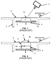
- an additive layer manufacturing apparatus comprises a vat 1 for containing a resin 2.
- a light source 3 is arranged to selectively focus on regions within layers of the resin 2 to initiate photo-polymerisation and build a 3 dimensional body of which a first layer 4 is shown.
- the first layer 4 is built on a build platform 5 which can be moved an upward and downward as represented by the two headed arrow beneath the build platform 5 in the Figure.
- the figure shows the top of the layer 4 just below the surface of the resin 6.
- the surface of the resin is substantially flat. This is typical at commencement of the additive layer manufacture and at a point where movement of the platform 5 has been arrested for some time.
- To build a second layer on to the first layer 4 the platform 5 is dropped into the resin 2 and then raised back to a surface level. This is sometimes termed "deep dipping".
- Figure 2 illustrates the apparatus of Figure 1 immediately after deep dipping.
- a second layer 9 sits on top surface 4a of the first layer 4. Due to viscosity and surface tension in the resin 2 a mound 8 of resin is formed on the surface 9a of the second layer 9. There then follows a waiting period while resin the mound 8 redistributes forming a flatter layer. Where the resin 2 is highly viscous, this can significantly delay the manufacture a body.
- the doctor blade 7 can be swept across the surface 6 to level the mound 8, however, when the build is only a few layers thick, this sweeping motion has an associated risk of stressing the build with a consequence of possible structural damage to the body.
- the vacuum doctor blade blade 37 is characterised by a cavity 30 extending from a tip 31 of the blade.
- the cavity 30 is connected to a suction device which removes air from the cavity 30 (as represented by the grey arrow above the blade) creating a vacuum effect at the tip 31.
- the tip 31 of vacuum doctor blade 37 is spaced a small distance d from the surface 36 of the resin 32. The distance is typically less than the thickness of a build layer. Since the tip is not directly contacting the surface 36, stress on the build is reduced compared to the arrangement of Figures 1 and 2 .
- the vacuum doctor blade 37 has just made a pass over layer 39.
- the surface 39a of the already formed layer 39 is lowered beneath the resin surface 36 by a distance equating to the desired layer thickness.
- a dip 40 results in the resin surface 36.
- the vacuum doctor blade 37 is swept in a reverse direction back over the surface layer 36.
- suction to the cavity 30 is ceased and consequently, as the tip 31 passes over dip 40, resin is released from the cavity 30 into the dip 40.
- Excess resin is now left on the surface 39a due to the stand-off height between the vacuum doctor blade 37 and the resin surface 36. This then requires a wait time to drain back off the surface 39a of the already formed layer 39.
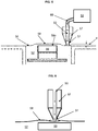
- FIG. 5 illustrates an embodiment of the invention of an additive layer manufacturing apparatus in accordance with the invention.
- the apparatus is shown at a point in the manufacture when a recently polymerised layer 59 has just been dipped in the resin 52 and raised back to the resin surface level 56 in a similar manner as described in relation to Figure 2 .
- a mound 58 is formed on the surface 59a of the polymerised layer 59.
- the vacuum blade of this apparatus has a cavity 50 passing through the doctor blade 57.
- the cavity has an outlet at a tip 51 of the doctor blade 57.
- a conduit 60 connects the cavity 50 to an air supply 53 which forces air through the conduit 60 and the cavity 50 towards the surface 56 of the resin.
- the tip 51 of the blade is positioned a small distance d from the surface level 56 of the resin 52 such that there is no direct contact between the two.
- FIGS 7, 8 and 9 illustrate optional adaptations of the tip 51 to control flow of air exiting at the tip 51.
- Figure 7 shows a section and an end view of a first optional adaptation of the doctor blade.
- the cavity 50 has convergent walls 61 towards the tip 51 resulting in a narrowed slot 62 in the tip.
- Figure 8 shows a section and an end view of a second optional adaptation of the doctor blade. As can be seen the tip 51 end of the cavity 50 is covered by a grid 63.
- Figure 9 shows a section and an end view of a third optional adaptation of the doctor blade.
- the tip 51 comprises a wall through which differently directed channels 64, 65 are provided.
- Figure 10 shows a section and an end view of a fourth optional adaptation of the doctor blade.
- the doctor blade 57 of this embodiment includes a follow blade 66 on one side of the doctor blade 57.
- the follower blade 66 is flexible as represented by the dotted outline and curved arrow in the Figure.
- a tip of the flexible follower blade 66 extends beyond the tip 51 of the of the doctor blade 57 by a distance d.
- the tip of the follow blade contacts the surface of the resin.
- the follow blade 66 is swept across the surface, it flexes thereby reducing stress on the surface layer.
- doctor blade 57 and associated air supply 53 may also be used to fill efficiently a dip in a resin surface.
- the apparatus of the invention may be applied to other additive layer manufacturing methods, for example powder bed ALM.
Landscapes
- Chemical & Material Sciences (AREA)
- Engineering & Computer Science (AREA)
- Materials Engineering (AREA)
- Manufacturing & Machinery (AREA)
- Physics & Mathematics (AREA)
- Optics & Photonics (AREA)
- Mechanical Engineering (AREA)
Claims (14)
- Additivschicht-Herstellungsvorrichtung, umfassend mehrere Rakelklingen (57), wobei jede Rakelklinge (57) eine Spitze (51) aufweist, die in der Verwendung proximal zu einer Materialschicht (59) angeordnet ist, die während eines Additivschicht-Herstellungsverfahrens erneut beschichtet werden soll, wobei die Rakelklinge (57) einen Hohlraum (50) mit einem Einlass und einem Auslass aufweist, wobei sich der Auslass an der Spitze (51) befindet und der Einlass mit einer Luftzufuhr (53) verbunden werden kann, wodurch Luft durch den Hohlraum (50) zu dem Auslass und auf eine Oberfläche (59a) der Materialschicht (59) geleitet werden kann, wobei jede Rakelklinge Merkmale stromabwärts von dem Auslass aufweist, die konfiguriert sind, um Luft, die aus dem Auslass austritt zu steuern und/oder zu leiten, und wobei die Luftzufuhr zu jeder Rakelklinge individuell steuerbar ist.
- Additivschicht-Herstellungsvorrichtung nach Anspruch 1, wobei die Merkmale ein Gitter, eine oder mehrere Düsen oder unterschiedlich ausgerichtete Kanäle beinhalten.
- Additivschicht-Herstellungsvorrichtung nach Anspruch 1 oder 2, wobei die Klingenspitze verjüngt sein kann, um einen konvergierenden oder divergierenden Auslass bereitzustellen.
- Additivschicht-Herstellungsvorrichtung nach einem vorherigen Anspruch, wobei die Luftzufuhr (53) eine Druckluftzufuhr ist.
- Additivschicht-Herstellungsvorrichtung nach einem vorherigen Anspruch, die ferner eine Durchflusssteuervorrichtung umfasst, die eingestellt werden kann, um die Geschwindigkeit und/oder den Druck der gerichteten Luftzufuhr zu variieren.
- Additivschicht-Herstellungsvorrichtung nach Anspruch 4 oder 5, wobei die Vorrichtung ferner eine Temperaturregelvorrichtung zum Einstellen und/oder Aufrechterhalten der Temperatur der Druckluftzufuhr beinhaltet.
- Additivschicht-Herstellungsvorrichtung nach einem vorherigen Anspruch, wobei die Rakelklinge flexibel ist.
- Additivschicht-Herstellungsvorrichtung nach einem vorherigen Anspruch, ferner umfassend eine flexible Folgeklinge, die angeordnet ist, um sich mit der Rakelklinge zu bewegen.
- Additivschicht-Herstellungsvorrichtung nach einem der Ansprüche 1 bis 6, umfassend mehrere Rakelklingen und wobei eine oder mehrere der Rakelklingen eine andere Konfiguration als andere aufweisen.
- Additivschicht-Herstellungsvorrichtung nach einem vorherigen Anspruch, ferner umfassend eine Bauplattform auf einer X-Y-Ebene und eine Indexierungsvorrichtung zum Bewegen der Rakelklinge in eine Richtung Z, orthogonal zu der X-Y-Ebene.
- Additivschicht-Herstellungsvorrichtung nach einem vorherigen Anspruch, ferner umfassend eine Wanne zum Enthalten eines flüssigen Materials, aus dem ein dreidimensionales Produkt gefertigt werden soll, und eine Vorrichtung zum Einleiten einer Polymerisation von Molekülen in dem flüssigen Material.
- Additivschicht-Herstellungsvorrichtung nach Anspruch 11, wobei die Vorrichtung zum Einleiten einer Polymerisation eine fokussierbare Lichtquelle in dem ultravioletten bis sichtbaren Bereich des elektromagnetischen Spektrums und einen Transportmechanismus zum Bewegen der Quelle über einen Abschnitt der Flüssigkeit umfasst.
- Additivschicht-Herstellungsvorrichtung nach einem der Ansprüche 1 bis 10, ferner umfassend einen Behälter für ein pulverförmiges Material, aus dem ein dreidimensionales Produkt gefertigt werden soll, und eine Vorrichtung zum Einleitung einer Fusion des Pulvers.
- Additivschicht-Herstellungsvorrichtung nach Anspruch 13, wobei die Vorrichtung zum Einleiten einer Fusion des Pulvers ein Laser oder ein Elektronenstrahlemitter ist.
Applications Claiming Priority (1)
| Application Number | Priority Date | Filing Date | Title |
|---|---|---|---|
| GBGB1704676.4A GB201704676D0 (en) | 2017-03-24 | 2017-03-24 | Recoater for additive layer manufature |
Publications (2)
| Publication Number | Publication Date |
|---|---|
| EP3378629A1 EP3378629A1 (de) | 2018-09-26 |
| EP3378629B1 true EP3378629B1 (de) | 2020-04-22 |
Family
ID=58687917
Family Applications (1)
| Application Number | Title | Priority Date | Filing Date |
|---|---|---|---|
| EP18159225.4A Active EP3378629B1 (de) | 2017-03-24 | 2018-02-28 | Nachbeschichter für regenerative schichtfertigung |
Country Status (3)
| Country | Link |
|---|---|
| US (1) | US10926465B2 (de) |
| EP (1) | EP3378629B1 (de) |
| GB (1) | GB201704676D0 (de) |
Families Citing this family (6)
| Publication number | Priority date | Publication date | Assignee | Title |
|---|---|---|---|---|
| EP4397425A3 (de) * | 2018-12-20 | 2024-08-14 | Concept Laser GmbH | Baumaterialhandhabungseinheit für ein pulvermodul für eine vorrichtung zur generativen fertigung eines dreidimensionalen objekts |
| WO2022051222A1 (en) | 2020-09-04 | 2022-03-10 | Vulcanforms Inc. | Defect mitigation for recoating systems for additive manufacturing |
| DE102020125403A1 (de) | 2020-09-29 | 2022-03-31 | Mühlbauer Technology Gmbh | 3D-Drucker und dessen Verwendung |
| US11110650B1 (en) * | 2020-10-02 | 2021-09-07 | Intrepid Automation | Vat-based additive manufacturing with dispensed material |
| US11772162B2 (en) * | 2020-10-29 | 2023-10-03 | GM Global Technology Operations LLC | Local collection of contaminants formed during metal powder bed fusion process |
| CN115157665B (zh) * | 2022-09-08 | 2022-12-06 | 季华实验室 | 基于气刀的连续3d打印方法及装置 |
Citations (2)
| Publication number | Priority date | Publication date | Assignee | Title |
|---|---|---|---|---|
| US20110024528A1 (en) * | 2009-07-30 | 2011-02-03 | Illinois Tool Works Inc. | Air knife |
| WO2017029623A1 (en) * | 2015-08-17 | 2017-02-23 | Landa Labs (2012) Ltd | Product metering device |
Family Cites Families (15)
| Publication number | Priority date | Publication date | Assignee | Title |
|---|---|---|---|---|
| DE1280673B (de) * | 1963-05-27 | 1968-10-17 | Fuji Photo Film Co Ltd | Geraet zum Aufbringen von Behandlungsloesungen auf lichtempfindliches Papier |
| DE2938521A1 (de) * | 1979-09-24 | 1981-04-09 | Hoechst Ag, 6000 Frankfurt | Dosiervorrichtung fuer lack |
| CA1337955C (en) | 1988-09-26 | 1996-01-23 | Thomas A. Almquist | Recoating of stereolithographic layers |
| US5238614A (en) * | 1991-05-28 | 1993-08-24 | Matsushita Electric Words, Ltd., Japan | Process of fabricating three-dimensional objects from a light curable resin liquid |
| JP2930455B2 (ja) | 1991-05-28 | 1999-08-03 | 松下電工株式会社 | 三次元形状の形成方法 |
| FR2713541B1 (fr) * | 1993-12-09 | 1997-04-30 | Laser Int Sa | Procédé et installation pour la fabrication de pièces par phototransformation de matière. |
| US5922364A (en) | 1997-03-03 | 1999-07-13 | Young, Jr.; Albert C. | Stereolithography layering control system |
| KR100408896B1 (ko) * | 1998-08-14 | 2004-01-24 | 엘지.필립스 엘시디 주식회사 | 티이에프티이 액정 디스플레이 디바이스 제조에 사용되는 에어커튼 |
| US6702101B2 (en) * | 2001-12-21 | 2004-03-09 | Spraying Systems Co. | Blower operated airknife with air augmenting shroud |
| US7045738B1 (en) | 2002-10-01 | 2006-05-16 | Southern Methodist University | Powder delivery system and method |
| US9682424B2 (en) | 2012-12-24 | 2017-06-20 | United Technologies Corporation | Absorbed impurities reduction in additive manufacturing systems |
| US9908158B2 (en) * | 2014-03-10 | 2018-03-06 | Ametek, Inc. | Air flow mechanism for image capture and vision systems |
| US20170368816A1 (en) * | 2014-12-23 | 2017-12-28 | Stratasys, Inc. | Resin slot extruder for additive manufacturing system |
| GB201602067D0 (en) | 2016-02-05 | 2016-03-23 | Rolls Royce Plc | Additive layer manufacturing |
| CN106392065B (zh) * | 2016-09-30 | 2019-07-23 | 西安铂力特增材技术股份有限公司 | 一种柔性铺粉装置及其制作方法 |
-
2017
- 2017-03-24 GB GBGB1704676.4A patent/GB201704676D0/en not_active Ceased
-
2018
- 2018-02-28 EP EP18159225.4A patent/EP3378629B1/de active Active
- 2018-03-21 US US15/927,268 patent/US10926465B2/en active Active
Patent Citations (2)
| Publication number | Priority date | Publication date | Assignee | Title |
|---|---|---|---|---|
| US20110024528A1 (en) * | 2009-07-30 | 2011-02-03 | Illinois Tool Works Inc. | Air knife |
| WO2017029623A1 (en) * | 2015-08-17 | 2017-02-23 | Landa Labs (2012) Ltd | Product metering device |
Also Published As
| Publication number | Publication date |
|---|---|
| US20180272604A1 (en) | 2018-09-27 |
| EP3378629A1 (de) | 2018-09-26 |
| US10926465B2 (en) | 2021-02-23 |
| GB201704676D0 (en) | 2017-05-10 |
Similar Documents
| Publication | Publication Date | Title |
|---|---|---|
| EP3378629B1 (de) | Nachbeschichter für regenerative schichtfertigung | |
| US10442176B2 (en) | Additive layer manufacturing | |
| US6838035B1 (en) | Rapid-prototyping method and apparatus | |
| JP6384826B2 (ja) | 三次元積層造形装置、三次元積層造形方法および三次元積層造形プログラム | |
| CN110167696B (zh) | 用于持续更新用于增材制造的重涂覆机刀片的方法及装置 | |
| US5340656A (en) | Three-dimensional printing techniques | |
| US12083738B2 (en) | Method, device, and recoating module for producing a three-dimensional object | |
| KR102021406B1 (ko) | 성형체를 제조하기 위한 방법 및 장치 | |
| CN120133539A (zh) | 制造模制层状产品的方法 | |
| TW201609606A (zh) | 燒結造形方法、液狀結合劑及燒結造形物 | |
| JP7127122B2 (ja) | 三次元成形体のリソグラフィベースの積層造形のための方法および装置 | |
| CN105848838A (zh) | 具有加速执行的用于3d打印方法的设备和方法 | |
| US20200238601A1 (en) | 3d-printed shaped parts made from more than one silicone material | |
| JP2012255554A (ja) | 超疎水性表面および製造方法 | |
| CN109843591B (zh) | 形成3d物体的方法 | |
| CN106985378A (zh) | 增材沉积系统和方法 | |
| JP6862917B2 (ja) | 三次元造形物製造用組成物および三次元造形物の製造方法 | |
| CN106985377A (zh) | 增材沉积系统和方法 | |
| JP7314174B2 (ja) | 固化可能な媒体から物体を層状に形成する為の方法及びシステム | |
| JPH0976354A (ja) | 立体造形装置 | |
| JP6919229B2 (ja) | 三次元造形物製造用組成物および三次元造形物の製造方法 | |
| US20250042085A1 (en) | Assembly and method for applying particulate building material in a 3d printer | |
| KR102142507B1 (ko) | 적층 가공 기술에 의해 세라믹 또는 금속 소재로 만든 피스를 제조하는 방법 및 머신 | |
| DE19853814B4 (de) | Verfahren zum Herstellen von Bauteilen durch Auftragstechnik | |
| JP6907657B2 (ja) | 三次元造形物の製造方法 |
Legal Events
| Date | Code | Title | Description |
|---|---|---|---|
| PUAI | Public reference made under article 153(3) epc to a published international application that has entered the european phase |
Free format text: ORIGINAL CODE: 0009012 |
|
| STAA | Information on the status of an ep patent application or granted ep patent |
Free format text: STATUS: THE APPLICATION HAS BEEN PUBLISHED |
|
| AK | Designated contracting states |
Kind code of ref document: A1 Designated state(s): AL AT BE BG CH CY CZ DE DK EE ES FI FR GB GR HR HU IE IS IT LI LT LU LV MC MK MT NL NO PL PT RO RS SE SI SK SM TR |
|
| AX | Request for extension of the european patent |
Extension state: BA ME |
|
| STAA | Information on the status of an ep patent application or granted ep patent |
Free format text: STATUS: REQUEST FOR EXAMINATION WAS MADE |
|
| 17P | Request for examination filed |
Effective date: 20190322 |
|
| RBV | Designated contracting states (corrected) |
Designated state(s): AL AT BE BG CH CY CZ DE DK EE ES FI FR GB GR HR HU IE IS IT LI LT LU LV MC MK MT NL NO PL PT RO RS SE SI SK SM TR |
|
| STAA | Information on the status of an ep patent application or granted ep patent |
Free format text: STATUS: EXAMINATION IS IN PROGRESS |
|
| 17Q | First examination report despatched |
Effective date: 20190912 |
|
| GRAP | Despatch of communication of intention to grant a patent |
Free format text: ORIGINAL CODE: EPIDOSNIGR1 |
|
| STAA | Information on the status of an ep patent application or granted ep patent |
Free format text: STATUS: GRANT OF PATENT IS INTENDED |
|
| RAP1 | Party data changed (applicant data changed or rights of an application transferred) |
Owner name: ROLLS-ROYCE PLC |
|
| GRAS | Grant fee paid |
Free format text: ORIGINAL CODE: EPIDOSNIGR3 |
|
| INTG | Intention to grant announced |
Effective date: 20200220 |
|
| GRAA | (expected) grant |
Free format text: ORIGINAL CODE: 0009210 |
|
| STAA | Information on the status of an ep patent application or granted ep patent |
Free format text: STATUS: THE PATENT HAS BEEN GRANTED |
|
| AK | Designated contracting states |
Kind code of ref document: B1 Designated state(s): AL AT BE BG CH CY CZ DE DK EE ES FI FR GB GR HR HU IE IS IT LI LT LU LV MC MK MT NL NO PL PT RO RS SE SI SK SM TR |
|
| REG | Reference to a national code |
Ref country code: CH Ref legal event code: EP |
|
| REG | Reference to a national code |
Ref country code: IE Ref legal event code: FG4D |
|
| REG | Reference to a national code |
Ref country code: DE Ref legal event code: R096 Ref document number: 602018003862 Country of ref document: DE |
|
| REG | Reference to a national code |
Ref country code: AT Ref legal event code: REF Ref document number: 1259525 Country of ref document: AT Kind code of ref document: T Effective date: 20200515 |
|
| REG | Reference to a national code |
Ref country code: LT Ref legal event code: MG4D |
|
| REG | Reference to a national code |
Ref country code: NL Ref legal event code: MP Effective date: 20200422 |
|
| PG25 | Lapsed in a contracting state [announced via postgrant information from national office to epo] |
Ref country code: LT Free format text: LAPSE BECAUSE OF FAILURE TO SUBMIT A TRANSLATION OF THE DESCRIPTION OR TO PAY THE FEE WITHIN THE PRESCRIBED TIME-LIMIT Effective date: 20200422 Ref country code: GR Free format text: LAPSE BECAUSE OF FAILURE TO SUBMIT A TRANSLATION OF THE DESCRIPTION OR TO PAY THE FEE WITHIN THE PRESCRIBED TIME-LIMIT Effective date: 20200723 Ref country code: PT Free format text: LAPSE BECAUSE OF FAILURE TO SUBMIT A TRANSLATION OF THE DESCRIPTION OR TO PAY THE FEE WITHIN THE PRESCRIBED TIME-LIMIT Effective date: 20200824 Ref country code: SE Free format text: LAPSE BECAUSE OF FAILURE TO SUBMIT A TRANSLATION OF THE DESCRIPTION OR TO PAY THE FEE WITHIN THE PRESCRIBED TIME-LIMIT Effective date: 20200422 Ref country code: NL Free format text: LAPSE BECAUSE OF FAILURE TO SUBMIT A TRANSLATION OF THE DESCRIPTION OR TO PAY THE FEE WITHIN THE PRESCRIBED TIME-LIMIT Effective date: 20200422 Ref country code: NO Free format text: LAPSE BECAUSE OF FAILURE TO SUBMIT A TRANSLATION OF THE DESCRIPTION OR TO PAY THE FEE WITHIN THE PRESCRIBED TIME-LIMIT Effective date: 20200722 Ref country code: FI Free format text: LAPSE BECAUSE OF FAILURE TO SUBMIT A TRANSLATION OF THE DESCRIPTION OR TO PAY THE FEE WITHIN THE PRESCRIBED TIME-LIMIT Effective date: 20200422 Ref country code: IS Free format text: LAPSE BECAUSE OF FAILURE TO SUBMIT A TRANSLATION OF THE DESCRIPTION OR TO PAY THE FEE WITHIN THE PRESCRIBED TIME-LIMIT Effective date: 20200822 |
|
| REG | Reference to a national code |
Ref country code: AT Ref legal event code: MK05 Ref document number: 1259525 Country of ref document: AT Kind code of ref document: T Effective date: 20200422 |
|
| PG25 | Lapsed in a contracting state [announced via postgrant information from national office to epo] |
Ref country code: HR Free format text: LAPSE BECAUSE OF FAILURE TO SUBMIT A TRANSLATION OF THE DESCRIPTION OR TO PAY THE FEE WITHIN THE PRESCRIBED TIME-LIMIT Effective date: 20200422 Ref country code: LV Free format text: LAPSE BECAUSE OF FAILURE TO SUBMIT A TRANSLATION OF THE DESCRIPTION OR TO PAY THE FEE WITHIN THE PRESCRIBED TIME-LIMIT Effective date: 20200422 Ref country code: BG Free format text: LAPSE BECAUSE OF FAILURE TO SUBMIT A TRANSLATION OF THE DESCRIPTION OR TO PAY THE FEE WITHIN THE PRESCRIBED TIME-LIMIT Effective date: 20200722 Ref country code: RS Free format text: LAPSE BECAUSE OF FAILURE TO SUBMIT A TRANSLATION OF THE DESCRIPTION OR TO PAY THE FEE WITHIN THE PRESCRIBED TIME-LIMIT Effective date: 20200422 |
|
| PG25 | Lapsed in a contracting state [announced via postgrant information from national office to epo] |
Ref country code: AL Free format text: LAPSE BECAUSE OF FAILURE TO SUBMIT A TRANSLATION OF THE DESCRIPTION OR TO PAY THE FEE WITHIN THE PRESCRIBED TIME-LIMIT Effective date: 20200422 |
|
| REG | Reference to a national code |
Ref country code: DE Ref legal event code: R097 Ref document number: 602018003862 Country of ref document: DE |
|
| PG25 | Lapsed in a contracting state [announced via postgrant information from national office to epo] |
Ref country code: ES Free format text: LAPSE BECAUSE OF FAILURE TO SUBMIT A TRANSLATION OF THE DESCRIPTION OR TO PAY THE FEE WITHIN THE PRESCRIBED TIME-LIMIT Effective date: 20200422 Ref country code: RO Free format text: LAPSE BECAUSE OF FAILURE TO SUBMIT A TRANSLATION OF THE DESCRIPTION OR TO PAY THE FEE WITHIN THE PRESCRIBED TIME-LIMIT Effective date: 20200422 Ref country code: CZ Free format text: LAPSE BECAUSE OF FAILURE TO SUBMIT A TRANSLATION OF THE DESCRIPTION OR TO PAY THE FEE WITHIN THE PRESCRIBED TIME-LIMIT Effective date: 20200422 Ref country code: DK Free format text: LAPSE BECAUSE OF FAILURE TO SUBMIT A TRANSLATION OF THE DESCRIPTION OR TO PAY THE FEE WITHIN THE PRESCRIBED TIME-LIMIT Effective date: 20200422 Ref country code: IT Free format text: LAPSE BECAUSE OF FAILURE TO SUBMIT A TRANSLATION OF THE DESCRIPTION OR TO PAY THE FEE WITHIN THE PRESCRIBED TIME-LIMIT Effective date: 20200422 Ref country code: SM Free format text: LAPSE BECAUSE OF FAILURE TO SUBMIT A TRANSLATION OF THE DESCRIPTION OR TO PAY THE FEE WITHIN THE PRESCRIBED TIME-LIMIT Effective date: 20200422 Ref country code: EE Free format text: LAPSE BECAUSE OF FAILURE TO SUBMIT A TRANSLATION OF THE DESCRIPTION OR TO PAY THE FEE WITHIN THE PRESCRIBED TIME-LIMIT Effective date: 20200422 Ref country code: AT Free format text: LAPSE BECAUSE OF FAILURE TO SUBMIT A TRANSLATION OF THE DESCRIPTION OR TO PAY THE FEE WITHIN THE PRESCRIBED TIME-LIMIT Effective date: 20200422 |
|
| PG25 | Lapsed in a contracting state [announced via postgrant information from national office to epo] |
Ref country code: SK Free format text: LAPSE BECAUSE OF FAILURE TO SUBMIT A TRANSLATION OF THE DESCRIPTION OR TO PAY THE FEE WITHIN THE PRESCRIBED TIME-LIMIT Effective date: 20200422 Ref country code: PL Free format text: LAPSE BECAUSE OF FAILURE TO SUBMIT A TRANSLATION OF THE DESCRIPTION OR TO PAY THE FEE WITHIN THE PRESCRIBED TIME-LIMIT Effective date: 20200422 |
|
| PLBE | No opposition filed within time limit |
Free format text: ORIGINAL CODE: 0009261 |
|
| STAA | Information on the status of an ep patent application or granted ep patent |
Free format text: STATUS: NO OPPOSITION FILED WITHIN TIME LIMIT |
|
| 26N | No opposition filed |
Effective date: 20210125 |
|
| PG25 | Lapsed in a contracting state [announced via postgrant information from national office to epo] |
Ref country code: SI Free format text: LAPSE BECAUSE OF FAILURE TO SUBMIT A TRANSLATION OF THE DESCRIPTION OR TO PAY THE FEE WITHIN THE PRESCRIBED TIME-LIMIT Effective date: 20200422 |
|
| PG25 | Lapsed in a contracting state [announced via postgrant information from national office to epo] |
Ref country code: MC Free format text: LAPSE BECAUSE OF FAILURE TO SUBMIT A TRANSLATION OF THE DESCRIPTION OR TO PAY THE FEE WITHIN THE PRESCRIBED TIME-LIMIT Effective date: 20200422 |
|
| REG | Reference to a national code |
Ref country code: BE Ref legal event code: MM Effective date: 20210228 |
|
| PG25 | Lapsed in a contracting state [announced via postgrant information from national office to epo] |
Ref country code: LI Free format text: LAPSE BECAUSE OF NON-PAYMENT OF DUE FEES Effective date: 20210228 Ref country code: LU Free format text: LAPSE BECAUSE OF NON-PAYMENT OF DUE FEES Effective date: 20210228 Ref country code: CH Free format text: LAPSE BECAUSE OF NON-PAYMENT OF DUE FEES Effective date: 20210228 |
|
| PG25 | Lapsed in a contracting state [announced via postgrant information from national office to epo] |
Ref country code: IE Free format text: LAPSE BECAUSE OF NON-PAYMENT OF DUE FEES Effective date: 20210228 |
|
| PG25 | Lapsed in a contracting state [announced via postgrant information from national office to epo] |
Ref country code: BE Free format text: LAPSE BECAUSE OF NON-PAYMENT OF DUE FEES Effective date: 20210228 |
|
| PG25 | Lapsed in a contracting state [announced via postgrant information from national office to epo] |
Ref country code: CY Free format text: LAPSE BECAUSE OF FAILURE TO SUBMIT A TRANSLATION OF THE DESCRIPTION OR TO PAY THE FEE WITHIN THE PRESCRIBED TIME-LIMIT Effective date: 20200422 |
|
| P01 | Opt-out of the competence of the unified patent court (upc) registered |
Effective date: 20230528 |
|
| PG25 | Lapsed in a contracting state [announced via postgrant information from national office to epo] |
Ref country code: HU Free format text: LAPSE BECAUSE OF FAILURE TO SUBMIT A TRANSLATION OF THE DESCRIPTION OR TO PAY THE FEE WITHIN THE PRESCRIBED TIME-LIMIT; INVALID AB INITIO Effective date: 20180228 |
|
| PG25 | Lapsed in a contracting state [announced via postgrant information from national office to epo] |
Ref country code: MK Free format text: LAPSE BECAUSE OF FAILURE TO SUBMIT A TRANSLATION OF THE DESCRIPTION OR TO PAY THE FEE WITHIN THE PRESCRIBED TIME-LIMIT Effective date: 20200422 |
|
| PG25 | Lapsed in a contracting state [announced via postgrant information from national office to epo] |
Ref country code: MT Free format text: LAPSE BECAUSE OF FAILURE TO SUBMIT A TRANSLATION OF THE DESCRIPTION OR TO PAY THE FEE WITHIN THE PRESCRIBED TIME-LIMIT Effective date: 20200422 |
|
| PGFP | Annual fee paid to national office [announced via postgrant information from national office to epo] |
Ref country code: DE Payment date: 20250226 Year of fee payment: 8 |
|
| PGFP | Annual fee paid to national office [announced via postgrant information from national office to epo] |
Ref country code: FR Payment date: 20250224 Year of fee payment: 8 |
|
| PGFP | Annual fee paid to national office [announced via postgrant information from national office to epo] |
Ref country code: GB Payment date: 20250218 Year of fee payment: 8 |
|
| PG25 | Lapsed in a contracting state [announced via postgrant information from national office to epo] |
Ref country code: TR Free format text: LAPSE BECAUSE OF FAILURE TO SUBMIT A TRANSLATION OF THE DESCRIPTION OR TO PAY THE FEE WITHIN THE PRESCRIBED TIME-LIMIT Effective date: 20200422 |