EP3377784B1 - Damping arrangement for at least one absorption mass - Google Patents
Damping arrangement for at least one absorption mass Download PDFInfo
- Publication number
- EP3377784B1 EP3377784B1 EP16784518.9A EP16784518A EP3377784B1 EP 3377784 B1 EP3377784 B1 EP 3377784B1 EP 16784518 A EP16784518 A EP 16784518A EP 3377784 B1 EP3377784 B1 EP 3377784B1
- Authority
- EP
- European Patent Office
- Prior art keywords
- damper element
- carrier
- absorption mass
- damping arrangement
- damper
- Prior art date
- Legal status (The legal status is an assumption and is not a legal conclusion. Google has not performed a legal analysis and makes no representation as to the accuracy of the status listed.)
- Active
Links
- 238000013016 damping Methods 0.000 title claims description 41
- 238000010521 absorption reaction Methods 0.000 title claims description 25
- 229920001971 elastomer Polymers 0.000 claims description 7
- 239000000806 elastomer Substances 0.000 claims description 7
- 239000000463 material Substances 0.000 claims description 6
- 238000001746 injection moulding Methods 0.000 claims description 5
- 238000009434 installation Methods 0.000 claims description 4
- 239000006096 absorbing agent Substances 0.000 description 83
- 230000008878 coupling Effects 0.000 description 4
- 238000010168 coupling process Methods 0.000 description 4
- 238000005859 coupling reaction Methods 0.000 description 4
- 230000005540 biological transmission Effects 0.000 description 2
- 238000004519 manufacturing process Methods 0.000 description 2
- 229910000831 Steel Inorganic materials 0.000 description 1
- 230000015572 biosynthetic process Effects 0.000 description 1
- 239000011248 coating agent Substances 0.000 description 1
- 238000000576 coating method Methods 0.000 description 1
- 238000002485 combustion reaction Methods 0.000 description 1
- 238000010276 construction Methods 0.000 description 1
- 230000000694 effects Effects 0.000 description 1
- 238000002347 injection Methods 0.000 description 1
- 239000007924 injection Substances 0.000 description 1
- 239000002184 metal Substances 0.000 description 1
- 230000035939 shock Effects 0.000 description 1
- 238000005507 spraying Methods 0.000 description 1
- 239000010959 steel Substances 0.000 description 1
- 230000001960 triggered effect Effects 0.000 description 1
Images
Classifications
-
- F—MECHANICAL ENGINEERING; LIGHTING; HEATING; WEAPONS; BLASTING
- F16—ENGINEERING ELEMENTS AND UNITS; GENERAL MEASURES FOR PRODUCING AND MAINTAINING EFFECTIVE FUNCTIONING OF MACHINES OR INSTALLATIONS; THERMAL INSULATION IN GENERAL
- F16F—SPRINGS; SHOCK-ABSORBERS; MEANS FOR DAMPING VIBRATION
- F16F15/00—Suppression of vibrations in systems; Means or arrangements for avoiding or reducing out-of-balance forces, e.g. due to motion
- F16F15/10—Suppression of vibrations in rotating systems by making use of members moving with the system
- F16F15/14—Suppression of vibrations in rotating systems by making use of members moving with the system using masses freely rotating with the system, i.e. uninvolved in transmitting driveline torque, e.g. rotative dynamic dampers
- F16F15/1407—Suppression of vibrations in rotating systems by making use of members moving with the system using masses freely rotating with the system, i.e. uninvolved in transmitting driveline torque, e.g. rotative dynamic dampers the rotation being limited with respect to the driving means
- F16F15/145—Masses mounted with play with respect to driving means thus enabling free movement over a limited range
-
- F—MECHANICAL ENGINEERING; LIGHTING; HEATING; WEAPONS; BLASTING
- F16—ENGINEERING ELEMENTS AND UNITS; GENERAL MEASURES FOR PRODUCING AND MAINTAINING EFFECTIVE FUNCTIONING OF MACHINES OR INSTALLATIONS; THERMAL INSULATION IN GENERAL
- F16F—SPRINGS; SHOCK-ABSORBERS; MEANS FOR DAMPING VIBRATION
- F16F15/00—Suppression of vibrations in systems; Means or arrangements for avoiding or reducing out-of-balance forces, e.g. due to motion
- F16F15/10—Suppression of vibrations in rotating systems by making use of members moving with the system
- F16F15/14—Suppression of vibrations in rotating systems by making use of members moving with the system using masses freely rotating with the system, i.e. uninvolved in transmitting driveline torque, e.g. rotative dynamic dampers
- F16F15/1407—Suppression of vibrations in rotating systems by making use of members moving with the system using masses freely rotating with the system, i.e. uninvolved in transmitting driveline torque, e.g. rotative dynamic dampers the rotation being limited with respect to the driving means
- F16F15/1414—Masses driven by elastic elements
Definitions
- the present invention relates to a damping arrangement for at least one damper mass of a damper system accommodated on a damper mass carrier with a damping device assigned to the at least one damper mass, which acts as a stop both in the radial direction and in the circumferential direction, the damping device having at least one damper element which provides the The absorber mass carrier is assigned at least along a part of its circumferential extent.
- damping arrangement is from the DE 10 2012 217 958 A1 known.
- the damper masses used there each have a damper mass middle part between two damper mass parts arranged with an axial offset from one another, which is in a form-fitting connection with the damping device and is enclosed by this on its sides facing the damper mass carrier.
- the damping device is intended to prevent a direct metallic impact of the absorber mass middle part against the absorber mass carrier.
- the damping device is accommodated on the absorber masses, since the installation space provided for the absorber masses is limited both in the radial direction, but in particular in the circumferential direction, they can only be made significantly smaller in the aforementioned directions than would be the case without such a damping device . This means that if the absorber masses are to be designed with the greatest possible weight, their inertia effect remains limited.
- a comparable damping arrangement is based on the DE 10 2012 214 214 A1 forth.
- the absorber mass carrier is assigned an annular damping device which is provided with damper elements in the form of radial projections.
- the contact surfaces of the damping device provided for contact with the absorber masses can be at least partially formed with a plastic or elastomer coating. Due to the design of the damper elements in shape of radial projections, the damping device consumes considerable installation space and, if made of metal, can considerably increase the mass of the damping arrangement.
- WO 2013/156733 A1 teaches a pendulum damping device for a motor vehicle transmission, the device having at least one pendulum mass, the middle part of which is movably mounted on a pivotable carrier.
- DE 10 2012 217 958 A1 teaches centrifugal pendulum, which contains a flange part rotating about an axis of rotation and axially on both sides of this limited pendulum masses received, two axially opposite pendulum masses being connected to each other to form a pair of pendulum masses.
- the invention is based on the object of designing a damping device for at least one absorber mass of a damper system received on a damper mass carrier in such a way that the best possible shock absorption can be provided without thereby having to accept weight disadvantages for the damping arrangement and / or inertia disadvantages for the damper masses.
- this object is achieved by a damping arrangement for at least one damper mass of a damper system received on a damper mass carrier with a damping device assigned to the at least one damper mass, which acts both in the radial direction and in the circumferential direction as a stop for the respective damper mass, wherein the damping device has at least one damper element which is assigned to the absorber mass carrier at least along part of its circumferential extent.
- the damper element of the damping device has a damper element carrier, which is accommodated on the damper mass carrier in a recess in the damper mass carrier provided for this purpose, and serves to accommodate a damper element support, which has a radial projection in the in which is effective as a stop for the respective damper mass Absorber mass carrier for the movement of the respective absorber mass protrudes space.
- the damper element can perform its function without forcing a limitation of the assigned absorber mass in its dimensions and thus in terms of its weight.
- damper element carrier as the first component consists at least essentially dimensionally stable material
- damper element support received on the damper element carrier as a second component made of an at least substantially deformable material.
- the damper element carrier as the first component can be made of steel to ensure the desired deformation stability, but the formation of this first component from dimensionally stable plastic brings advantages in particular compared to the absorber mass, such as friction or wear behavior.
- both components of the damper element as the damper element carrier and the damper element support, are made of plastic, both components are preferably made from injection molding, which results in manufacturing advantages.
- the second component can be firmly connected to the first component by spraying onto the first component with little manufacturing effort.
- the first component is particularly advantageously designed with a geometric profile on its side facing the second component, a counter-profile being formed when the second component is sprayed on, which is in a form-fitting connection with the profile of the first component.
- a positive connection is also advantageous if an elastomer is used as the second component.
- the elastomer is also provided on its side facing the first component with a counter-profile suitable for profiling the first component.
- the damper element carrier and thus the first component can be assigned an axial lock.
- This can be provided directly on the damper element carrier or on a component axially adjacent to the damper element carrier.
- An axial securing device provided on the damper element carrier is preferably combined with an axial securing device which is provided on a component axially adjacent to the damper element carrier, since this results in the possibility arises of inserting the damper element carrier in a first axial direction into the cutout of the absorber mass carrier intended for this purpose until the first axial securing device has been reached, in order then to at least substantially secure the damper element carrier against backward movement by inserting the corresponding axially adjacent component.
- the adjacent component then acts as a second axial securing device as soon as it has reached its desired relative position with respect to the damper element carrier.
- the damper element On its side facing the absorber mass carrier, the damper element has at least one damper element arm which engages in a corresponding recess section of the recess in the absorber mass carrier.
- the at least one damper element arm of the damper element has a cross-sectional widening at a free end, which engages in a corresponding recess widening of the recess section, there is a positive connection of the damper element to the absorber mass carrier, so that the damper element is held securely in the absorber mass carrier even under the influence of centrifugal force .
- the at least one damper element arm on the damper element has at least one extension component in the radial direction and thus in the effective direction of the centrifugal force.
- the damper element preferably has, on its side facing the respective absorber mass, in a circumferential area which, regardless of the respective deflection position of the absorber mass, is at least uninterruptedly covered by it, has a radial projection which is effective in association with a radial bulge on a absorber mass part of the absorber mass.
- This radial projection means that the radial projection in relation to the assigned absorber mass can perform this stop function when the absorber mass requires a stop that is effective in the radial direction, and on the other hand when the absorber mass executes a movement in which it does this Function of the radial projection is not required, does not experience any contact with the radial projection, and can therefore move freely without any form-fitting disability.
- the latter state is particularly the case when operating the absorber masses take place at a speed at which the centrifugal force exceeds the weight, while the radial projection, for example at very low speed, when the centrifugal force falls below the weight, performs its stop function. Since the respective absorber mass can come into contact with the radial projection from both possible deflection directions in the latter operating mode, wear, if triggered at all, will take place evenly.
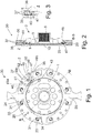
- FIG. 1 and 2 show an absorber system 30 with an absorber mass carrier 25 rotatable about a central axis 10 and with a plurality of absorber masses 29 received on the absorber mass carrier 25.
- the absorber mass carrier 25 is formed by a hub disk 1 which is centered and fastened on a hub 3.
- the hub 3 has an internal toothing 5 for transmitting an applied torque to an output, not shown, such as a transmission input shaft.
- the absorber system 30 and thus also the hub disc 1 are part of a damping arrangement 2, for example in the form of a known and therefore not shown torsional vibration damper.
- the hub disc 1 is designed as an absorber mass carrier 25, this has the character of how Fig. 3 in the illustration without absorber masses shows first guideways 27, while second guideways 31 are provided in absorber masses 29.
- the guideways 27 in the absorber mass carrier 25 are connected to the guideways 31 in the absorber masses 29 by means of a roller-shaped coupling element 33, which is opposite both guideways 27 and 31 is relatively movable, and should ideally roll against these guideways 27 and 31.
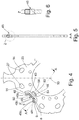
- the absorber masses 29 each consist of several absorber mass parts 35, 36 and 37 in the axial direction, of which the two absorber mass parts 35 and 36, such as Fig. 2 shows, are arranged on both sides of the hub disc 1 and thus the absorber mass carrier 25, while the third absorber mass part 37 axially between the other two absorber mass parts 35 and 36 and according to Fig. 1 , is accommodated in a construction space 40 of the absorber mass carrier 25.
- the three damper mass parts 35 to 37 are connected to one another by means of riveting 41.
- a damping device 47 is accommodated radially within the axially central damper mass part 37, which in the present case has a single damper element 45, but can also be designed with a plurality of damper elements.
- the damper element 45 is how Fig. 4 shows more clearly, received in a recess 43 of the absorber mass carrier 25.
- the damper element 45 also serves in the direction of the axially central absorber mass part 37 ( Fig. 1 ) protruding radial projections 48 in the sense of stops 49a and 49b effective in the circumferential direction for the axially central absorber mass part 37 and thus also for the entire absorber mass 29.
- the recess 43 receiving the damper element 45 has a recess section 54 ( Fig. 4 ), which have a recess widening 56 at its free end.
- a damper element arm 58 is provided on the damper element 45, which has a cross-sectional widening 60 including an axial extension 61 at its free end. The damper element arm 58 is moved by movement transverse to that in FIG Fig. 4 Extension direction of the damper element 45 shown inserted into the recess section 54, whereby the cross-sectional widening 60 is also introduced into the recess widening 56.
- the recess widening 56 secures the cross-sectional widening 60 against centrifugal forces, and thus, via the damper element arm 58, also a damper element carrier 6 of the damper element 45 Fig. 1 Central axis shown 10.
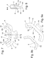
- the damper element carrier 6 of the damper element 45 serves to receive a damper element support 7.
- the damper element carrier 6 is designed for this purpose on its side facing the damper element support 7 with a profile 62, which consists, for example, of a plurality of individual webs 64 formed with an undercut, which extend almost across the entire width of the damper element carrier 6 transversely to it Fig. 9a extending direction shown.
- the damper element support 7 has notches 66, which form a counter-profiling 68 for profiling 62.
- the grooves 66 run almost across the entire width of the damper element support 7 transverse to it in Fig. 9b direction of extension shown.
- the damper element support 7 is held securely on the damper element carrier 6 due to the connection of the profiling 62 / counter-profiling 68 by means of a plurality of webs 64 / grooves 66. This means that centrifugal forces are not critical to the existence of the damper element 45 even if the damper element support 7 should be designed to be particularly deformable.
- the damper element carrier 6 serves as an at least substantially dimensionally stable first component 8 of the damper element 45, while the damper element support 7 serves as an at least substantially deformable second component 9 of the damper element 45.
- both components 8 and 9, i.e. damper element support 6 and damper element support 7, are each designed as injection molded parts, then it makes sense that component 9, i.e. damper element support 7, is sprayed onto component 8, i.e. damper element support 6, and this creates the connection between the profiling 62 and the counter-profiling 68.
- a nose 70 is formed on an axial end of the damper element carrier 6, which secures the damper element carrier 6 against falling out of the absorber mass carrier 25, and is thus effective as an axial securing means 72.
- a further axial securing means 74 effective in the opposite direction is provided by the in Fig. 2 shown hub 3 of the hub disc 1 is formed.
- the guideways 27, 31 are provided in pairs, each of which has a curved course.
- the guideways 27 on the absorber mass carrier 25 each have an exit area 14 ( Fig. 4 ), in which the respective guideway 27 has the greatest radial distance from the central axis 10.
- the guideways 31 provided on the absorber masses 29 also have a curved course, each with an exit area 24 ( Fig. 1 ), in which the respective guideway 31 has the smallest radial distance from the central axis 10.
- the state of the absorber masses 29 during driving is in Fig. 1 shown, and is present when the absorber system 30 is operated at a speed at which the centrifugal force exceeds the weight.
- torsional vibrations When driving, torsional vibrations can force deflections of the absorber masses 29 from their starting position 32 in the circumferential direction, as a result of which the coupling elements 33 from the output areas 14, 24 of the guideways 27, 31 are deflected, however, with the decaying torsional vibration under the action of centrifugal force, the coupling elements 33 are always reset to the starting position.
- the deflection range of the absorber masses 29 is limited by the fact that the radial bulge 52 on the absorber mass part 37 abuts against the stop 49a assigned to this direction of rotation or 49b has reached. Since the damper element support 7 of the damper element 45 is preferably designed to be deformable, this contact becomes soft and takes place with little noise.
Description
Die vorliegende Erfindung betrifft eine Dämpfungsanordnung für wenigstens eine an einem Tilgermassenträger aufgenommene Tilgermasse eines Tilgersystems mit einer der wenigstens einen Tilgermasse zugeordneten Dämpfungseinrichtung, die sowohl in Radialrichtung als auch in Umfangsrichtung eine Wirkung als Anschlag entfaltet, wobei die Dämpfungseinrichtung über zumindest ein Dämpferelement verfügt, das dem Tilgermassenträger zumindest entlang eines Teils von dessen Umfangserstreckung zugeordnet ist.The present invention relates to a damping arrangement for at least one damper mass of a damper system accommodated on a damper mass carrier with a damping device assigned to the at least one damper mass, which acts as a stop both in the radial direction and in the circumferential direction, the damping device having at least one damper element which provides the The absorber mass carrier is assigned at least along a part of its circumferential extent.
Eine derartige Dämpfungsanordnung ist aus der
Da die Dämpfungseinrichtung an den Tilgermassen aufgenommen ist, können dieselben, da der für die Tilgermassen vorgesehene Bauraum sowohl in Radialrichtung, insbesondere aber in Umfangsrichtung, begrenzt ist, in den vorgenannten Richtungen nur deutlich kleiner ausgebildet sein, als dies ohne eine derartige Dämpfungseinrichtung der Fall wäre. Dadurch bleibt dann, wenn die Tilgermassen mit möglichst großem Gewicht ausgebildet sein sollen, deren Trägheitswirkung eingeschränkt.Since the damping device is accommodated on the absorber masses, since the installation space provided for the absorber masses is limited both in the radial direction, but in particular in the circumferential direction, they can only be made significantly smaller in the aforementioned directions than would be the case without such a damping device . This means that if the absorber masses are to be designed with the greatest possible weight, their inertia effect remains limited.
Eine vergleichbare Dämpfungsanordnung geht aus der
Der Erfindung liegt die Aufgabe zugrunde, eine Dämpfungseinrichtung für wenigstens eine an einem Tilgermassenträger aufgenommene Tilgermasse eines Tilgersystems so auszubilden, dass die bestmögliche Anschlagdämpfung bereitgestellt werden kann, ohne hierdurch Gewichtsnachteile für die Dämpfungsanordnung und/oder Trägheitsnachteile für die Tilgermassen akzeptieren zu müssen.The invention is based on the object of designing a damping device for at least one absorber mass of a damper system received on a damper mass carrier in such a way that the best possible shock absorption can be provided without thereby having to accept weight disadvantages for the damping arrangement and / or inertia disadvantages for the damper masses.
Gemäß dem wesentlichen Aspekt der Erfindung wird diese Aufgabe gelöst durch eine Dämpfungsanordnung für wenigstens eine an einem Tilgermassenträger aufgenommene Tilgermasse eines Tilgersystems mit einer der wenigstens einen Tilgermasse zugeordneten Dämpfungseinrichtung, die sowohl in Radialrichtung als auch in Umfangsrichtung eine Wirkung als Anschlag für die jeweilige Tilgermasse entfaltet, wobei die Dämpfungseinrichtung über zumindest ein Dämpferelement verfügt, das dem Tilgermassenträger zumindest entlang eines Teils von dessen Umfangserstreckung zugeordnet ist.According to the essential aspect of the invention, this object is achieved by a damping arrangement for at least one damper mass of a damper system received on a damper mass carrier with a damping device assigned to the at least one damper mass, which acts both in the radial direction and in the circumferential direction as a stop for the respective damper mass, wherein the damping device has at least one damper element which is assigned to the absorber mass carrier at least along part of its circumferential extent.
Von besonderer Bedeutung ist hierbei, dass das Dämpferelement der Dämpfungseinrichtung über einen Dämpferelemententräger verfügt, der am Tilgermassenträger in einer hierfür vorgesehenen Aussparung des Tilgermassenträgers aufgenommen ist, und zur Aufnahme einer Dämpferelementenauflage dient, die mit einem als Anschlag für die jeweilige Tilgermasse wirksamen Radialvorsprung in den im Tilgermassenträger für die Bewegung der jeweiligen Tilgermasse vorgesehenen Bauraum ragt.It is particularly important here that the damper element of the damping device has a damper element carrier, which is accommodated on the damper mass carrier in a recess in the damper mass carrier provided for this purpose, and serves to accommodate a damper element support, which has a radial projection in the in which is effective as a stop for the respective damper mass Absorber mass carrier for the movement of the respective absorber mass protrudes space.
Aufgrund dieser Aufnahme des Dämpferelementes am Tilgermassenträger kann das Dämpferelement seine Funktion erfüllen, ohne eine Begrenzung der zugeordneten Tilgermasse in deren Abmessungen und damit bezüglich deren Gewichtes zu erzwingen.Due to this inclusion of the damper element on the absorber mass carrier, the damper element can perform its function without forcing a limitation of the assigned absorber mass in its dimensions and thus in terms of its weight.
Von besonderer Bedeutung ist die Ausbildung des Dämpferelementes mit zwei Komponenten, von denen ein Dämpferelemententräger als erste Komponente aus einem zumindest im Wesentlichen formstabilen Werkstoff besteht, und eine an dem Dämpferelemententräger aufgenommene Dämpferelementenauflage als zweite Komponente aus einem zumindest im Wesentlichen verformbaren Werkstoff. Der Dämpferelemententräger als erste Komponente kann zur Gewährleistung der gewünschten Verformungsstabilität zwar aus Stahl bestehen, jedoch bringt die Ausbildung dieser ersten Komponente aus formstabilem Kunststoff Vorteile insbesondere gegenüber der Tilgermasse, wie beispielsweise beim Reib- oder Verschleißverhalten. Bei Verwendung einer Dämpferelementenauflage aus einem Kunststoff, der gegenüber dem Kunststoff des Dämpferelemententrägers besser verformbar ist, oder aus einem Elastomer, wird die von der zweiten Komponente gewünschte Nachgiebigkeit erbracht, so dass bei einem Kontakt des Dämpferelemententrägers mit der Tilgermasse dieselbe jeweils weich und damit geräuscharm zum Stillstand gebracht werden kann. Bei Ausbildung beider Komponenten des Dämpferelementes, als von Dämpferelemententräger und von Dämpferelementenauflage, aus Kunststoff sind beide Komponenten mit Vorzug aus Spritzguss hergestellt, wodurch sich Fertigungsvorteile ergeben. Insbesondere kann hierbei die zweite Komponente durch Aufspritzen auf die erste Komponente mit geringem Fertigungsaufwand mit der ersten Komponente fest verbunden werden. Mit besonderem Vorteil ist die erste Komponente hierfür an ihrer der zweiten Komponente zugewandten Seite mit einer geometrischen Profilierung ausgebildet, wobei sich beim Aufspritzen der zweiten Komponente eine Gegenprofilierung ausbildet, die mit der Profilierung der ersten Komponente in formschlüssiger Verbindung steht. Selbstverständlich ist eine solche formschlüssige Verbindung aber auch dann vorteilhaft, wenn als zweite Komponente ein Elastomer Verwendung findet. In diesem Fall ist auch der Elastomer an seiner der ersten Komponente zugewandten Seite mit einer zur Profilierung der ersten Komponente passenden Gegenprofilierung versehen.Of particular importance is the design of the damper element with two components, one of which is a damper element carrier as the first component consists at least essentially dimensionally stable material, and a damper element support received on the damper element carrier as a second component made of an at least substantially deformable material. The damper element carrier as the first component can be made of steel to ensure the desired deformation stability, but the formation of this first component from dimensionally stable plastic brings advantages in particular compared to the absorber mass, such as friction or wear behavior. When using a damper element support made of a plastic, which is better deformable compared to the plastic of the damper element carrier, or of an elastomer, the flexibility required by the second component is provided, so that when the damper element carrier comes into contact with the absorber mass, the same is soft and therefore low in noise Can be brought to a standstill. When both components of the damper element, as the damper element carrier and the damper element support, are made of plastic, both components are preferably made from injection molding, which results in manufacturing advantages. In particular, the second component can be firmly connected to the first component by spraying onto the first component with little manufacturing effort. To this end, the first component is particularly advantageously designed with a geometric profile on its side facing the second component, a counter-profile being formed when the second component is sprayed on, which is in a form-fitting connection with the profile of the first component. Of course, such a positive connection is also advantageous if an elastomer is used as the second component. In this case, the elastomer is also provided on its side facing the first component with a counter-profile suitable for profiling the first component.
Darüber hinaus kann dem Dämpferelemententräger und damit der ersten Komponente eine Axialsicherung zugeordnet sein. Diese kann unmittelbar am Dämpferelemententräger vorgesehen sein, oder aber an einem zum Dämpferelemententräger axial benachbarten Bauteil. Mit Vorzug wird eine am Dämpferelemententräger vorgesehene Axialsicherung mit einer Axialsicherung kombiniert, die an einem zum Dämpferelemententräger axial benachbarten Bauteil vorgesehen ist, da sich hierdurch die Möglichkeit ergibt, den Dämpferelemententräger in einer ersten Axialrichtung in die hierfür bestimmte Aussparung des Tilgermassenträgers bis zum Erreichen der ersten Axialsicherung einzuschieben, um den Dämpferelemententräger anschließend durch Einlegen des entsprechenden, axial benachbarten Bauteils gegen eine Rückbewegung zumindest im Wesentlichen zu sichern. Das benachbarte Bauteil wirkt dann, sobald es seine gewünschte Relativposition gegenüber dem Dämpferelemententräger erreicht hat, als zweite Axialsicherung.In addition, the damper element carrier and thus the first component can be assigned an axial lock. This can be provided directly on the damper element carrier or on a component axially adjacent to the damper element carrier. An axial securing device provided on the damper element carrier is preferably combined with an axial securing device which is provided on a component axially adjacent to the damper element carrier, since this results in the possibility arises of inserting the damper element carrier in a first axial direction into the cutout of the absorber mass carrier intended for this purpose until the first axial securing device has been reached, in order then to at least substantially secure the damper element carrier against backward movement by inserting the corresponding axially adjacent component. The adjacent component then acts as a second axial securing device as soon as it has reached its desired relative position with respect to the damper element carrier.
Das Dämpferelement verfügt an seiner dem Tilgermassenträger zugewandten Seite über wenigstens einen Dämpferelementenarm , welcher in einen entsprechenden Aussparungsabschnitt der Aussparung des Tilgermassenträgers eingreift. Insbesondere dann, wenn der wenigstens eine Dämpferelementenarm des Dämpferelementes an einem freien Ende eine Querschnittsaufweitung aufweist, welche in eine entsprechende Aussparungsaufweitung des Aussparungsabschnittes eingreift, ergibt sich eine formschlüssige Anbindung des Dämpferelementes an den Tilgermassenträger, so dass das Dämpferelement auch unter Fliehkrafteinfluss sicher im Tilgermassenträger gehalten ist. Um besonders gut gegen Fliehkrafteinfluss gesichert zu sein, ist es sinnvoll, wenn der zumindest eine Dämpferelementenarm am Dämpferelement zumindest eine Erstreckungskomponente in Radialrichtung und damit in Wirkrichtung der Fliehkraft aufweist.On its side facing the absorber mass carrier, the damper element has at least one damper element arm which engages in a corresponding recess section of the recess in the absorber mass carrier. In particular, if the at least one damper element arm of the damper element has a cross-sectional widening at a free end, which engages in a corresponding recess widening of the recess section, there is a positive connection of the damper element to the absorber mass carrier, so that the damper element is held securely in the absorber mass carrier even under the influence of centrifugal force . In order to be particularly well secured against the influence of centrifugal force, it makes sense if the at least one damper element arm on the damper element has at least one extension component in the radial direction and thus in the effective direction of the centrifugal force.
Mit Vorzug verfügt das Dämpferelement an seiner der jeweiligen Tilgermasse zugewandten Seite in einem Umfangsbereich, welcher ungeachtet von der jeweiligen Auslenkposition der Tilgermasse unterbrechungsfrei von derselben zumindest überdeckt ist, über einen Radialvorsprung, der in Zuordnung zu einer Radialauswölbung an einem Tilgermassenteil der Tilgermasse wirksam ist. Eine geschickte Gestaltung dieses Radialvorsprunges bewirkt hierbei, dass der Radialvorsprung in Bezug auf die zugeordnete Tilgermasse dann, wenn die Tilgermasse eines in Radialrichtung wirksamen Anschlags bedarf, diese Anschlagfunktion wahrnehmen kann, und andererseits, wenn die Tilgermasse eine Bewegung vollzieht, in welcher sie diese Funktion des Radialvorsprunges nicht benötigt, keinen Kontakt mit dem Radialvorsprung erfährt, und somit ihre Bewegung frei von formschlüssiger Behinderung vollziehen kann. Der letztgenannte Zustand wird insbesondere bei Betrieb der Tilgermassen mit einer Drehzahl erfolgen, bei welcher die Fliehkraft die Gewichtskraft übersteigt, während der Radialvorsprung beispielsweise bei sehr geringer Drehzahl, wenn die Fliehkraft die Gewichtskraft unterfällt, seine Anschlagfunktion wahrnimmt. Da die jeweilige Tilgermasse bei der letztgenannten Betriebsweise aus beiden möglichen Auslenkungsrichtungen in Kontakt mit dem Radialvorsprung gelangen kann, wird ein Verschleiß, sofern ein solcher überhaupt ausgelöst wird, gleichmäßig erfolgen.The damper element preferably has, on its side facing the respective absorber mass, in a circumferential area which, regardless of the respective deflection position of the absorber mass, is at least uninterruptedly covered by it, has a radial projection which is effective in association with a radial bulge on a absorber mass part of the absorber mass. A clever design of this radial projection means that the radial projection in relation to the assigned absorber mass can perform this stop function when the absorber mass requires a stop that is effective in the radial direction, and on the other hand when the absorber mass executes a movement in which it does this Function of the radial projection is not required, does not experience any contact with the radial projection, and can therefore move freely without any form-fitting disability. The latter state is particularly the case when operating the absorber masses take place at a speed at which the centrifugal force exceeds the weight, while the radial projection, for example at very low speed, when the centrifugal force falls below the weight, performs its stop function. Since the respective absorber mass can come into contact with the radial projection from both possible deflection directions in the latter operating mode, wear, if triggered at all, will take place evenly.
Durch Ausbildung des Dämpferelementes in seinen jeweiligen umfangsseitigen Endbereichen mit jeweils in Richtung zum zugeordneten Tilgermassenteil der entsprechenden Tilgermasse überstehenden Radialvorsprüngen entstehen jeweils in Umfangsrichtung wirksame Anschläge, die mit dem zugeordneten Tilgermassenteil der entsprechenden Tilgermasse zusammenwirken. Diese jeweils in Umfangsrichtung wirksamen Anschläge sind, in Umfangsrichtung gesehen, beidseits des in Radialrichtung wirksamen Anschlags vorgesehen.By forming the damper element in its respective circumferential end regions with radial projections projecting in the direction of the assigned absorber mass part of the corresponding absorber mass, effective stops are produced in the circumferential direction, which interact with the assigned absorber mass part of the corresponding absorber mass. These stops which are effective in the circumferential direction are, seen in the circumferential direction, provided on both sides of the stop which is effective in the radial direction.
Die Erfindung wird nachfolgend anhand der beiliegenden Figuren detailliert beschrieben. Es zeigt:
-
Fig. 1 Eine Draufsicht auf ein Tilgersystem mit einem durch eine Nabenscheibe gebildeten Tilgermassenträger und mit Tilgermassen; -
Fig. 2 eine Schnittdarstellung des Tilgersystems derFig. 1 gemäß der Schnittlinie B - B; -
Fig. 3 eine vergrößerte Herauszeichnung des inFig. 2 eingekreisten Bereichs Z; -
Fig. 4 eine Herauszeichnung eines Segments der inFig. 1 gezeigten Nabenscheibe mit einem Dämpferelement; -
Fig. 5 eine Schnittdarstellung der Nabenscheibe derFig. 4 gemäß der Schnittlinie A - A durch das Dämpferelement; -
Fig. 6 eine vergrößerte Herauszeichnung des Dämpferelements gemäß des inFig. 5 eingekreisten Bereichs Z; -
Fig. 7 einen Teilschnitt durch das ausFig. 4 als Einzelheit entnommene Dämpferelement mit Dämpferelemententräger und Dämpferelementenauflage; -
Fig. 8 eine Schnittdarstellung des Dämpferelements derFig. 7 gemäß der Schnittlinie B - B; -
Fig. 9a eine Darstellung des Dämpferelemententrägers; -
Fig. 9b eine Darstellung der Dämpferelementenauflage.
-
Fig. 1 A plan view of an absorber system with an absorber mass carrier formed by a hub disc and with absorber masses; -
Fig. 2 a sectional view of the absorber system ofFig. 1 according to section line B - B; -
Fig. 3 an enlarged drawing of the inFig. 2 circled area Z; -
Fig. 4 a highlight of a segment of the inFig. 1 hub disc shown with a damper element; -
Fig. 5 a sectional view of the hub disc of theFig. 4 according to section line A - A through the damper element; -
Fig. 6 an enlarged drawing of the damper element according to the inFig. 5 circled area Z; -
Fig. 7 a partial section through thatFig. 4 damper element taken as a detail with damper element carrier and damper element support; -
Fig. 8 a sectional view of the damper element ofFig. 7 according to section line B - B; -
Fig. 9a a representation of the damper element carrier; -
Fig. 9b a representation of the damper element support.
Das Tilgersystem 30 und damit auch die Nabenscheibe 1 sind Teil einer Dämpfungsanordnung 2, beispielsweise in Form eines bekannten und daher nicht gezeigten Torsionsschwingungsdämpfers. Da die Nabenscheibe 1 als Tilgermassenträger 25 ausgebildet ist, weist diese, wie
Die Tilgermassen 29 bestehen in Achsrichtung jeweils aus mehreren Tilgermassenteilen 35, 36 und 37, von denen die beiden Tilgermassenteile 35 und 36, wie
Radial innerhalb des axial mittleren Tilgermassenteils 37 ist eine Dämpfungseinrichtung 47 aufgenommen, die im vorliegenden Fall über ein einzelnes Dämpferelement 45 verfügt, ebenso aber auch mit einer Mehrzahl an Dämpferelementen ausgebildet sein kann. Das Dämpferelement 45 ist, wie
Die das Dämpferelement 45 aufnehmende Aussparung 43 verfügt über einen Aussparungsabschnitt 54 (
Der Dämpferelemententräger 6 des Dämpferelementes 45 dient zur Aufnahme einer Dämpferelementenauflage 7. Wie
Der Dämpferelemententräger 6 dient als zumindest im Wesentlichen formstabile erste Komponente 8 des Dämpferelementes 45, die Dämpferelementenauflage 7 dagegen als zumindest im Wesentlichen verformbare zweite Komponente 9 des Dämpferelementes 45.The
Bei Verwendung eines Elastomers als Dämpferelementenauflage 7 sind die Nutungen 66 bereits vor einer Verbindung der Dämpferelementenauflage 7 mit dem Dämpferelemententräger 6 vorhanden, so dass durch eine Aufschiebebewegung senkrecht zu den in den
Eine weitere Besonderheit des Dämpferelemententrägers 6 ist insbesondere in
Am Tilgermassenträger 25 sind, ebenso wie an den Tilgermassen 29, jeweils paarweise, die Führungsbahnen 27, 31 vorgesehen, die jeweils über einen gekrümmten Verlauf verfügen. Die Führungsbahnen 27 am Tilgermassenträger 25 verfügen über je einen Ausgangsbereich 14 (
Bei Fahrbetrieb können Torsionsschwingungen zwar Auslenkungen der Tilgermassen 29 aus deren Ausgangsposition 32 in Umfangsrichtung erzwingen, wodurch die Koppelelemente 33 aus den Ausgangsbereichen 14, 24 der Führungsbahnen 27, 31 ausgelenkt werden, jedoch erfolgt bei abklingender Torsionsschwingung unter der Wirkung der Fliehkraft stets eine Rückstellung der Koppelelemente 33 in die Ausgangsposition. Sollte der Eintrag von Torsionsschwingungen allerdings so stark sein, dass eine übermäßig starke Auslenkung der Tilgermassen 29 in Umfangsrichtung die Folge wäre, dann wird die Auslenkweite der Tilgermassen 29 dadurch begrenzt, dass die Radialauswölbung 52 am Tilgermassenteil 37 in Anlage an dem dieser Drehrichtung zugeordneten Anschlag 49a oder 49b gelangt ist. Da die Dämpferelementenauflage 7 des Dämpferelementes 45 mit Vorzug verformbar ausgebildet ist, wird dieser Kontakt weich und mit geringer Geräuschentwicklung erfolgen.On the
When driving, torsional vibrations can force deflections of the
Es sind auch Betriebszustände denkbar, bei welchen die Tilgermassen 29 eine Verlagerung radial in Richtung zur Zentralachse erfahren, beispielsweise wenn beim Stillsetzen der Brennkraftmaschine das Tilgersystem 30 mit einer Drehzahl betrieben wird, bei welcher die Fliehkraft die Gewichtskraft unterfällt. In diesem Fall wird die Bewegung der Tilgermassen 29 begrenzt, indem die Radialauswölbung 52 am Tilgermassenteil 37 an der dieser Radialauswölbung 52 zugewandten Seite des Dämpferelementes 45 in Anlage gekommen ist, insbesondere hierbei an dessen Radialvorsprung 50. Auch mit dem Anschlag 49c erfolgt der Kontakt wegen der Ausbildung des Dämpferelementes 45 als Elastomer weich und mit geringer Geräuschentwicklung.Operating states are also conceivable in which the
- 11
- NabenscheibeHub disc
- 22nd
- DämpfungsanordnungDamping arrangement
- 33rd
- Nabehub
- 55
- InnenverzahnungInternal teeth
- 66
- DämpferelemententrägerDamper element carrier
- 77
- DämpferelementenauflageDamper element support
- 88th
- erste Komponente des Dämpferelementesfirst component of the damper element
- 99
- zweite Komponente des Dämpferelementessecond component of the damper element
- 1010th
- ZentralachseCentral axis
- 1111
- AntriebsflanschDrive flange
- 1313
- AbdeckblechCover plate
- 1414
- AusgangsbereichExit area
- 1515
- AufnahmeraumRecording room
- 1717th
- UmfangsfedersatzCircumferential spring set
- 1919th
- GleitelementeSliding elements
- 2121
- antriebsseitige Ansteuerelementecontrol elements on the drive side
- 2323
- abtriebsseitige Ansteuerelementeoutput-side control elements
- 2424th
- AusgangsbereichExit area
- 2525th
- TilgermassenträgerAbsorber mass carrier
- 2727
- erste Führungsbahnenfirst guideways
- 2929
- TilgermassenAbsorber masses
- 3030th
- TilgersystemTilger system
- 3131
- zweite Führungsbahnensecond guideways
- 3232
- AusgangspositionStarting position
- 3333
- walzenförmiges Koppelelementroller-shaped coupling element
- 3535
- TilgermassenteilAbsorber mass part
- 3636
- TilgermassenteilAbsorber mass part
- 3737
- TilgermassenteilAbsorber mass part
- 4040
- BauraumInstallation space
- 4141
- VernietungRiveting
- 4343
- AussparungRecess
- 4545
- DämpferelementDamper element
- 4747
- DämpfungseinrichtungDamping device
- 4848
- RadialvorsprüngeRadial projections
- 4949
- Anschlägeattacks
- 5050
- Radialvorsprung DämpferelementRadial projection damper element
- 5252
- Radialauswölbung TilgermassenteilRadial bulge absorber mass part
- 5454
- AussparungsabschnittRecess section
- 5656
- AussparungsaufweitungGap expansion
- 5858
- DämpferelementenarmDamper element arm
- 6060
- QuerschnittsaufweitungCross-sectional expansion
- 6161
- Axialverlängerung am DämpferelementenarmAxial extension on the damper element arm
- 6262
- ProfilierungProfiling
- 6464
- StegeWalkways
- 6666
- NutungenGrooves
- 6868
- GegenprofilierungCounter-profiling
- 7070
- Nasenose
- 7272
- AxialsicherungAxial lock
- 7474
- AxialsicherungAxial lock
Claims (14)
- Damping arrangement (2) for at least one absorption mass (29), which is received on an absorption mass carrier (25), of an absorption system (30), having a damping device (47) which is assigned to the at least one absorption mass (29) and which acts as a stop (49a to 49c) for the respective absorption mass (29) both in the radial direction and in the circumferential direction, wherein the damping device (47) has at least one damper element (45) which is assigned to the absorption mass carrier (25) at least along part of its circumferential extent, characterized in that the damper element (45) has a first component (8) in the form of a damper element carrier (6) which is received on the absorption mass carrier (25) in a recess (43) provided for this purpose, and serves for receiving a second component (9) in the form of a damper element pad (7) which, by way of a radial projection (48, 50) which acts as a stop (49a to 49c) for the respective absorption mass (29), protrudes into the installation space (40) provided in the absorption mass carrier (25) for the movement of the respective absorption mass (29), characterized in that the damper element (45) has, on its side facing the absorption mass carrier (25), at least one damper element arm (58) which engages in a corresponding recess portion (54) of the recess (43) of the absorption mass carrier (25).
- Damping arrangement (2) according to Claim 1, characterized in that the at least one damper element arm (58) has, at a free end, a cross-sectional widening (60) which engages in a corresponding recess widening (56) of the recess portion (54).
- Damping arrangement (2) according to Claim 1, characterized in that the at least one damper element arm (58) is oriented at least substantially in the direction of a central axis (10) of the absorption system (30) and engages in a correspondingly oriented recess widening (56) of the recess (43).
- Damping arrangement (2) according to Claim 2, characterized in that the at least one damper element arm (58) has an axial extension (61) at its free end which engages in the recess widening (56) of the recess portion (54).
- Damping arrangement (2) according to Claim 1, characterized in that the damper element carrier (6), as first component (8) of the damper element (45), consists of a dimensionally stable material while, by contrast, the damper element pad (7), as second component (8) of the damper element (45), consists of a deformable material.
- Damping arrangement (2) according to Claim 5, characterized in that the damper element carrier (6), and hence the first component (8) of the damper element (45), consist of an injection moulding having a first material characteristic, whereas the damper element pad (7), and hence the second component (8) of the damper element (45), consist of an injection moulding having a second material characteristic or of an elastomer.
- Damping arrangement (2) according to Claim 6, characterized in that the damper element carrier (6) is formed, on its side facing the damper element pad (7), with a profiling (62) with which a counter-profiling (68) provided on the damper element pad (7) serves for producing a form-fitting operative connection.
- Damping arrangement (2) according to Claims 6 and 7, characterized in that the counter-profiling (68) of the damper element pad (7) arises by applying the injection moulding of the second component (9) to the damper element carrier (6) of the first component (8), wherein enclosure of webs (64) of the profiling (62) of the damper element carrier (6) by the injection moulding over at least the most part of the length of extent of the webs (64) of the profiling (62) is to be sought.
- Damping arrangement (2) according to Claim 1, characterized in that the damper element carrier (6) is held in the recess (43) of the absorption mass carrier (25) by way of axial securing means (72, 74) .
- Damping arrangement (2) according to Claim 9, characterized in that at least one axial securing means (72) is part of the damper element carrier (6) .
- Damping arrangement (2) according to Claim 1, characterized in that the damper element (45) has, on its side facing the respective absorption mass (29), a radial projection (50) in a circumferential region which, irrespective of the respective deflection position of the absorption mass (29), is at least covered by the latter without interruption, said radial projection acting in association with a radial bulge (52) provided on an absorption mass part (37) of the absorption mass (29).
- Damping arrangement (2) according to Claim 11, characterized in that the radial projection (50) on the damper element (45), in association with the radial bulge (52) on the absorption mass part (37) of the absorption mass (29), serves as a stop (49c) which acts in the radial direction.
- Damping arrangement (2) according to Claim 12, characterized in that the damper element (45) is formed, in its respective circumferential end regions, in each case with radial projections (48) which project in the direction of the absorption mass part (37) and which, in each case in association with the absorption mass part (37), serve in each case as stops (49a, 49b) for the corresponding absorption mass (29) which act in the circumferential direction.
- Damping arrangement (2) according to Claims 12 and 13, characterized in that the stops (49a, 49b) acting in the circumferential direction are provided in the circumferential direction on both sides of the stop (49c) acting in the radial direction.
Applications Claiming Priority (2)
| Application Number | Priority Date | Filing Date | Title |
|---|---|---|---|
| DE102015222822.3A DE102015222822A1 (en) | 2015-11-19 | 2015-11-19 | Damping arrangement for at least one absorber mass |
| PCT/EP2016/075333 WO2017084829A1 (en) | 2015-11-19 | 2016-10-21 | Damping arrangement for at least one absorption mass |
Publications (2)
| Publication Number | Publication Date |
|---|---|
| EP3377784A1 EP3377784A1 (en) | 2018-09-26 |
| EP3377784B1 true EP3377784B1 (en) | 2020-04-29 |
Family
ID=57178424
Family Applications (1)
| Application Number | Title | Priority Date | Filing Date |
|---|---|---|---|
| EP16784518.9A Active EP3377784B1 (en) | 2015-11-19 | 2016-10-21 | Damping arrangement for at least one absorption mass |
Country Status (4)
| Country | Link |
|---|---|
| EP (1) | EP3377784B1 (en) |
| CN (1) | CN108350983A (en) |
| DE (1) | DE102015222822A1 (en) |
| WO (1) | WO2017084829A1 (en) |
Families Citing this family (8)
| Publication number | Priority date | Publication date | Assignee | Title |
|---|---|---|---|---|
| DE102018001878A1 (en) * | 2018-03-08 | 2019-09-12 | Borgwarner Inc. | Centrifugal pendulum device and torsional vibration damper with such a centrifugal pendulum device |
| DE102018210292A1 (en) * | 2018-06-25 | 2020-01-02 | Zf Friedrichshafen Ag | Torsional vibration damping arrangement |
| DE102018120943A1 (en) * | 2018-08-28 | 2020-03-05 | Schaeffler Technologies AG & Co. KG | Centrifugal pendulum |
| DE102018222244A1 (en) * | 2018-12-19 | 2020-06-25 | Zf Friedrichshafen Ag | Torsional vibration damping arrangement |
| DE102019201875A1 (en) | 2019-02-13 | 2020-08-13 | Zf Friedrichshafen Ag | Torsional vibration damping arrangement |
| DE102019206575A1 (en) * | 2019-05-08 | 2020-11-12 | Zf Friedrichshafen Ag | Stop arrangement for damper masses of a damper system |
| DE102019208068A1 (en) * | 2019-06-04 | 2020-12-10 | Zf Friedrichshafen Ag | Damper system |
| DE102019006650A1 (en) * | 2019-09-21 | 2021-03-25 | Borg Warner Inc. | Centrifugal pendulum device |
Family Cites Families (10)
| Publication number | Priority date | Publication date | Assignee | Title |
|---|---|---|---|---|
| DE19914871C2 (en) * | 1999-04-01 | 2003-06-12 | Freudenberg Carl Kg | Speed-adaptive vibration damper |
| EP1744074A3 (en) * | 2005-07-11 | 2008-10-01 | LuK Lamellen und Kupplungsbau Beteiligungs KG | Torque transfer device |
| DE102009042831A1 (en) * | 2008-10-27 | 2010-04-29 | Luk Lamellen Und Kupplungsbau Beteiligungs Kg | Drive train for motor vehicle, has clutch unit arranged between internal-combustion engine and gear box, and centrifugal force pendulum integrated in clutch unit and formed by multiple centrifugal force pendulum elements |
| DE102012214214A1 (en) | 2011-09-05 | 2013-03-07 | Schaeffler Technologies AG & Co. KG | Centrifugal pendulum for oscillation damping of coupling device, has stopping element mounted on flange and connected with inner edge of masses along radial direction of pendulum, so that radial motion of masses is limited |
| FR2989753B1 (en) * | 2012-04-20 | 2014-04-18 | Valeo Embrayages | PENDULAR DAMPING DEVICE, ESPECIALLY FOR A MOTOR VEHICLE TRANSMISSION |
| DE102012217958A1 (en) | 2012-10-01 | 2014-04-03 | Schaeffler Technologies Gmbh & Co. Kg | Centrifugal pendulum for powertrain of motor car, has hinged damping element that is provided in flange of pendulum mass pair, and is extended on both sides of intermediary element |
| DE102013204711A1 (en) * | 2013-03-18 | 2014-09-18 | Zf Friedrichshafen Ag | Tilgerschwingungsdämpfer |
| DE102013204713A1 (en) * | 2013-03-18 | 2014-09-18 | Zf Friedrichshafen Ag | Tilgerschwingungsdämpfer |
| DE102013217090A1 (en) * | 2013-08-28 | 2015-03-05 | Zf Friedrichshafen Ag | absorber system |
| CN204592137U (en) * | 2015-02-13 | 2015-08-26 | 柳州金鸿橡塑有限公司 | Rubber torsional vibration damper |
-
2015
- 2015-11-19 DE DE102015222822.3A patent/DE102015222822A1/en not_active Withdrawn
-
2016
- 2016-10-21 EP EP16784518.9A patent/EP3377784B1/en active Active
- 2016-10-21 WO PCT/EP2016/075333 patent/WO2017084829A1/en unknown
- 2016-10-21 CN CN201680067320.6A patent/CN108350983A/en active Pending
Non-Patent Citations (1)
| Title |
|---|
| None * |
Also Published As
| Publication number | Publication date |
|---|---|
| WO2017084829A1 (en) | 2017-05-26 |
| CN108350983A (en) | 2018-07-31 |
| EP3377784A1 (en) | 2018-09-26 |
| DE102015222822A1 (en) | 2017-05-24 |
Similar Documents
| Publication | Publication Date | Title |
|---|---|---|
| EP3377784B1 (en) | Damping arrangement for at least one absorption mass | |
| EP2516887B1 (en) | Centrifugal pendulum mechanism | |
| WO2015028234A1 (en) | Vibration absorber system | |
| DE8103147U1 (en) | Damping disc for torque transmission | |
| DE102013217090A1 (en) | absorber system | |
| DE102006010270B4 (en) | gearing | |
| DE102011085106A1 (en) | Torsional vibration damping device for use in torque transmission device of motor vehicle, has flange provided with recess, and absorber mass that is connected with flange, where distance element is connected to absorber material | |
| WO2015144169A1 (en) | Centrifugal force pendulum comprising a spring arrangement | |
| DE10209933A1 (en) | Counter track link has inner and outer hubs with axles, raceways between drive and driven ends, annular cage with inner and outer hubs, balls and radial windows | |
| DE3433903A1 (en) | CLUTCH DISC | |
| WO2015165669A1 (en) | Tuned mass damper and method for providing a tuned mass damper | |
| DE19709343B4 (en) | Torsional vibration damper with a friction device | |
| DE2256582C3 (en) | Disc damping arrangement for friction clutches | |
| DE102017108465A1 (en) | Sway control device | |
| DE102017110682A1 (en) | Support flange for a centrifugal pendulum | |
| WO2008071281A1 (en) | Torsional vibration damper comprising end blocks and drive train comprising said torsional vibration damper | |
| DE102018131322A1 (en) | Multi-flange torsional vibration damper with at least two equally flanged hub flanges and a torque limiter | |
| DE102009052978A1 (en) | Torque transmission device i.e. torsional vibration damper, for internal combustion engine of motor vehicle, has energy storages accommodated in annular space formed from sections of one flywheel unit, where sections have identical parts | |
| DE102017127090A1 (en) | centrifugal pendulum | |
| DE19711145B4 (en) | Torsion damper with washer, especially for motor vehicles | |
| DE102016101535A1 (en) | torsion damping | |
| DE102016208493A1 (en) | Centrifugal pendulum device with stop for spherical rollers | |
| DE4443206A1 (en) | Flywheel device for automobile | |
| DE19626687A1 (en) | Torsional vibration dampener for motor vehicle - has hub containing multiple dampening springs used in conjunction with shoulders and pre-dampening accumulators | |
| DE102009015576A1 (en) | Torsional vibration damper for use as e.g. damper stage of divided flywheel, has anti-twist protection device for energy storage provided in one of disk parts in impact regions, where disk parts have elastic windows for retaining storage |
Legal Events
| Date | Code | Title | Description |
|---|---|---|---|
| STAA | Information on the status of an ep patent application or granted ep patent |
Free format text: STATUS: UNKNOWN |
|
| STAA | Information on the status of an ep patent application or granted ep patent |
Free format text: STATUS: THE INTERNATIONAL PUBLICATION HAS BEEN MADE |
|
| PUAI | Public reference made under article 153(3) epc to a published international application that has entered the european phase |
Free format text: ORIGINAL CODE: 0009012 |
|
| STAA | Information on the status of an ep patent application or granted ep patent |
Free format text: STATUS: REQUEST FOR EXAMINATION WAS MADE |
|
| 17P | Request for examination filed |
Effective date: 20180418 |
|
| AK | Designated contracting states |
Kind code of ref document: A1 Designated state(s): AL AT BE BG CH CY CZ DE DK EE ES FI FR GB GR HR HU IE IS IT LI LT LU LV MC MK MT NL NO PL PT RO RS SE SI SK SM TR |
|
| AX | Request for extension of the european patent |
Extension state: BA ME |
|
| DAV | Request for validation of the european patent (deleted) | ||
| DAX | Request for extension of the european patent (deleted) | ||
| GRAP | Despatch of communication of intention to grant a patent |
Free format text: ORIGINAL CODE: EPIDOSNIGR1 |
|
| STAA | Information on the status of an ep patent application or granted ep patent |
Free format text: STATUS: GRANT OF PATENT IS INTENDED |
|
| INTG | Intention to grant announced |
Effective date: 20191127 |
|
| GRAS | Grant fee paid |
Free format text: ORIGINAL CODE: EPIDOSNIGR3 |
|
| GRAA | (expected) grant |
Free format text: ORIGINAL CODE: 0009210 |
|
| STAA | Information on the status of an ep patent application or granted ep patent |
Free format text: STATUS: THE PATENT HAS BEEN GRANTED |
|
| AK | Designated contracting states |
Kind code of ref document: B1 Designated state(s): AL AT BE BG CH CY CZ DE DK EE ES FI FR GB GR HR HU IE IS IT LI LT LU LV MC MK MT NL NO PL PT RO RS SE SI SK SM TR |
|
| REG | Reference to a national code |
Ref country code: GB Ref legal event code: FG4D Free format text: NOT ENGLISH |
|
| REG | Reference to a national code |
Ref country code: CH Ref legal event code: EP |
|
| REG | Reference to a national code |
Ref country code: AT Ref legal event code: REF Ref document number: 1263793 Country of ref document: AT Kind code of ref document: T Effective date: 20200515 |
|
| REG | Reference to a national code |
Ref country code: DE Ref legal event code: R096 Ref document number: 502016009784 Country of ref document: DE |
|
| REG | Reference to a national code |
Ref country code: IE Ref legal event code: FG4D Free format text: LANGUAGE OF EP DOCUMENT: GERMAN |
|
| REG | Reference to a national code |
Ref country code: NL Ref legal event code: MP Effective date: 20200429 |
|
| REG | Reference to a national code |
Ref country code: LT Ref legal event code: MG4D |
|
| PG25 | Lapsed in a contracting state [announced via postgrant information from national office to epo] |
Ref country code: IS Free format text: LAPSE BECAUSE OF FAILURE TO SUBMIT A TRANSLATION OF THE DESCRIPTION OR TO PAY THE FEE WITHIN THE PRESCRIBED TIME-LIMIT Effective date: 20200829 Ref country code: NO Free format text: LAPSE BECAUSE OF FAILURE TO SUBMIT A TRANSLATION OF THE DESCRIPTION OR TO PAY THE FEE WITHIN THE PRESCRIBED TIME-LIMIT Effective date: 20200729 Ref country code: PT Free format text: LAPSE BECAUSE OF FAILURE TO SUBMIT A TRANSLATION OF THE DESCRIPTION OR TO PAY THE FEE WITHIN THE PRESCRIBED TIME-LIMIT Effective date: 20200831 Ref country code: FI Free format text: LAPSE BECAUSE OF FAILURE TO SUBMIT A TRANSLATION OF THE DESCRIPTION OR TO PAY THE FEE WITHIN THE PRESCRIBED TIME-LIMIT Effective date: 20200429 Ref country code: SE Free format text: LAPSE BECAUSE OF FAILURE TO SUBMIT A TRANSLATION OF THE DESCRIPTION OR TO PAY THE FEE WITHIN THE PRESCRIBED TIME-LIMIT Effective date: 20200429 Ref country code: GR Free format text: LAPSE BECAUSE OF FAILURE TO SUBMIT A TRANSLATION OF THE DESCRIPTION OR TO PAY THE FEE WITHIN THE PRESCRIBED TIME-LIMIT Effective date: 20200730 Ref country code: LT Free format text: LAPSE BECAUSE OF FAILURE TO SUBMIT A TRANSLATION OF THE DESCRIPTION OR TO PAY THE FEE WITHIN THE PRESCRIBED TIME-LIMIT Effective date: 20200429 |
|
| PG25 | Lapsed in a contracting state [announced via postgrant information from national office to epo] |
Ref country code: BG Free format text: LAPSE BECAUSE OF FAILURE TO SUBMIT A TRANSLATION OF THE DESCRIPTION OR TO PAY THE FEE WITHIN THE PRESCRIBED TIME-LIMIT Effective date: 20200729 Ref country code: HR Free format text: LAPSE BECAUSE OF FAILURE TO SUBMIT A TRANSLATION OF THE DESCRIPTION OR TO PAY THE FEE WITHIN THE PRESCRIBED TIME-LIMIT Effective date: 20200429 Ref country code: RS Free format text: LAPSE BECAUSE OF FAILURE TO SUBMIT A TRANSLATION OF THE DESCRIPTION OR TO PAY THE FEE WITHIN THE PRESCRIBED TIME-LIMIT Effective date: 20200429 Ref country code: LV Free format text: LAPSE BECAUSE OF FAILURE TO SUBMIT A TRANSLATION OF THE DESCRIPTION OR TO PAY THE FEE WITHIN THE PRESCRIBED TIME-LIMIT Effective date: 20200429 |
|
| PG25 | Lapsed in a contracting state [announced via postgrant information from national office to epo] |
Ref country code: NL Free format text: LAPSE BECAUSE OF FAILURE TO SUBMIT A TRANSLATION OF THE DESCRIPTION OR TO PAY THE FEE WITHIN THE PRESCRIBED TIME-LIMIT Effective date: 20200429 Ref country code: AL Free format text: LAPSE BECAUSE OF FAILURE TO SUBMIT A TRANSLATION OF THE DESCRIPTION OR TO PAY THE FEE WITHIN THE PRESCRIBED TIME-LIMIT Effective date: 20200429 |
|
| PG25 | Lapsed in a contracting state [announced via postgrant information from national office to epo] |
Ref country code: EE Free format text: LAPSE BECAUSE OF FAILURE TO SUBMIT A TRANSLATION OF THE DESCRIPTION OR TO PAY THE FEE WITHIN THE PRESCRIBED TIME-LIMIT Effective date: 20200429 Ref country code: SM Free format text: LAPSE BECAUSE OF FAILURE TO SUBMIT A TRANSLATION OF THE DESCRIPTION OR TO PAY THE FEE WITHIN THE PRESCRIBED TIME-LIMIT Effective date: 20200429 Ref country code: DK Free format text: LAPSE BECAUSE OF FAILURE TO SUBMIT A TRANSLATION OF THE DESCRIPTION OR TO PAY THE FEE WITHIN THE PRESCRIBED TIME-LIMIT Effective date: 20200429 Ref country code: IT Free format text: LAPSE BECAUSE OF FAILURE TO SUBMIT A TRANSLATION OF THE DESCRIPTION OR TO PAY THE FEE WITHIN THE PRESCRIBED TIME-LIMIT Effective date: 20200429 Ref country code: RO Free format text: LAPSE BECAUSE OF FAILURE TO SUBMIT A TRANSLATION OF THE DESCRIPTION OR TO PAY THE FEE WITHIN THE PRESCRIBED TIME-LIMIT Effective date: 20200429 Ref country code: CZ Free format text: LAPSE BECAUSE OF FAILURE TO SUBMIT A TRANSLATION OF THE DESCRIPTION OR TO PAY THE FEE WITHIN THE PRESCRIBED TIME-LIMIT Effective date: 20200429 Ref country code: ES Free format text: LAPSE BECAUSE OF FAILURE TO SUBMIT A TRANSLATION OF THE DESCRIPTION OR TO PAY THE FEE WITHIN THE PRESCRIBED TIME-LIMIT Effective date: 20200429 |
|
| REG | Reference to a national code |
Ref country code: DE Ref legal event code: R097 Ref document number: 502016009784 Country of ref document: DE |
|
| PG25 | Lapsed in a contracting state [announced via postgrant information from national office to epo] |
Ref country code: PL Free format text: LAPSE BECAUSE OF FAILURE TO SUBMIT A TRANSLATION OF THE DESCRIPTION OR TO PAY THE FEE WITHIN THE PRESCRIBED TIME-LIMIT Effective date: 20200429 Ref country code: SK Free format text: LAPSE BECAUSE OF FAILURE TO SUBMIT A TRANSLATION OF THE DESCRIPTION OR TO PAY THE FEE WITHIN THE PRESCRIBED TIME-LIMIT Effective date: 20200429 |
|
| PLBE | No opposition filed within time limit |
Free format text: ORIGINAL CODE: 0009261 |
|
| STAA | Information on the status of an ep patent application or granted ep patent |
Free format text: STATUS: NO OPPOSITION FILED WITHIN TIME LIMIT |
|
| 26N | No opposition filed |
Effective date: 20210201 |
|
| PG25 | Lapsed in a contracting state [announced via postgrant information from national office to epo] |
Ref country code: SI Free format text: LAPSE BECAUSE OF FAILURE TO SUBMIT A TRANSLATION OF THE DESCRIPTION OR TO PAY THE FEE WITHIN THE PRESCRIBED TIME-LIMIT Effective date: 20200429 |
|
| REG | Reference to a national code |
Ref country code: CH Ref legal event code: PL |
|
| GBPC | Gb: european patent ceased through non-payment of renewal fee |
Effective date: 20201021 |
|
| PG25 | Lapsed in a contracting state [announced via postgrant information from national office to epo] |
Ref country code: LU Free format text: LAPSE BECAUSE OF NON-PAYMENT OF DUE FEES Effective date: 20201021 Ref country code: MC Free format text: LAPSE BECAUSE OF FAILURE TO SUBMIT A TRANSLATION OF THE DESCRIPTION OR TO PAY THE FEE WITHIN THE PRESCRIBED TIME-LIMIT Effective date: 20200429 |
|
| REG | Reference to a national code |
Ref country code: BE Ref legal event code: MM Effective date: 20201031 |
|
| PG25 | Lapsed in a contracting state [announced via postgrant information from national office to epo] |
Ref country code: BE Free format text: LAPSE BECAUSE OF NON-PAYMENT OF DUE FEES Effective date: 20201031 Ref country code: CH Free format text: LAPSE BECAUSE OF NON-PAYMENT OF DUE FEES Effective date: 20201031 Ref country code: LI Free format text: LAPSE BECAUSE OF NON-PAYMENT OF DUE FEES Effective date: 20201031 Ref country code: GB Free format text: LAPSE BECAUSE OF NON-PAYMENT OF DUE FEES Effective date: 20201021 |
|
| PG25 | Lapsed in a contracting state [announced via postgrant information from national office to epo] |
Ref country code: IE Free format text: LAPSE BECAUSE OF NON-PAYMENT OF DUE FEES Effective date: 20201021 |
|
| PG25 | Lapsed in a contracting state [announced via postgrant information from national office to epo] |
Ref country code: TR Free format text: LAPSE BECAUSE OF FAILURE TO SUBMIT A TRANSLATION OF THE DESCRIPTION OR TO PAY THE FEE WITHIN THE PRESCRIBED TIME-LIMIT Effective date: 20200429 Ref country code: MT Free format text: LAPSE BECAUSE OF FAILURE TO SUBMIT A TRANSLATION OF THE DESCRIPTION OR TO PAY THE FEE WITHIN THE PRESCRIBED TIME-LIMIT Effective date: 20200429 Ref country code: CY Free format text: LAPSE BECAUSE OF FAILURE TO SUBMIT A TRANSLATION OF THE DESCRIPTION OR TO PAY THE FEE WITHIN THE PRESCRIBED TIME-LIMIT Effective date: 20200429 |
|
| PG25 | Lapsed in a contracting state [announced via postgrant information from national office to epo] |
Ref country code: MK Free format text: LAPSE BECAUSE OF FAILURE TO SUBMIT A TRANSLATION OF THE DESCRIPTION OR TO PAY THE FEE WITHIN THE PRESCRIBED TIME-LIMIT Effective date: 20200429 |
|
| PGFP | Annual fee paid to national office [announced via postgrant information from national office to epo] |
Ref country code: FR Payment date: 20220908 Year of fee payment: 7 |
|
| REG | Reference to a national code |
Ref country code: AT Ref legal event code: MM01 Ref document number: 1263793 Country of ref document: AT Kind code of ref document: T Effective date: 20211021 |
|
| PG25 | Lapsed in a contracting state [announced via postgrant information from national office to epo] |
Ref country code: AT Free format text: LAPSE BECAUSE OF NON-PAYMENT OF DUE FEES Effective date: 20211021 |
|
| P01 | Opt-out of the competence of the unified patent court (upc) registered |
Effective date: 20230528 |
|
| PGFP | Annual fee paid to national office [announced via postgrant information from national office to epo] |
Ref country code: DE Payment date: 20230830 Year of fee payment: 8 |