EP3377781B1 - Selbstzentrierende rollenführung - Google Patents
Selbstzentrierende rollenführung Download PDFInfo
- Publication number
- EP3377781B1 EP3377781B1 EP16801962.8A EP16801962A EP3377781B1 EP 3377781 B1 EP3377781 B1 EP 3377781B1 EP 16801962 A EP16801962 A EP 16801962A EP 3377781 B1 EP3377781 B1 EP 3377781B1
- Authority
- EP
- European Patent Office
- Prior art keywords
- roller
- tube
- self
- centring
- magnetic
- Prior art date
- Legal status (The legal status is an assumption and is not a legal conclusion. Google has not performed a legal analysis and makes no representation as to the accuracy of the status listed.)
- Active
Links
Images


Classifications
-
- F—MECHANICAL ENGINEERING; LIGHTING; HEATING; WEAPONS; BLASTING
- F16—ENGINEERING ELEMENTS AND UNITS; GENERAL MEASURES FOR PRODUCING AND MAINTAINING EFFECTIVE FUNCTIONING OF MACHINES OR INSTALLATIONS; THERMAL INSULATION IN GENERAL
- F16C—SHAFTS; FLEXIBLE SHAFTS; ELEMENTS OR CRANKSHAFT MECHANISMS; ROTARY BODIES OTHER THAN GEARING ELEMENTS; BEARINGS
- F16C29/00—Bearings for parts moving only linearly
- F16C29/04—Ball or roller bearings
- F16C29/045—Ball or roller bearings having rolling elements journaled in one of the moving parts
-
- F—MECHANICAL ENGINEERING; LIGHTING; HEATING; WEAPONS; BLASTING
- F16—ENGINEERING ELEMENTS AND UNITS; GENERAL MEASURES FOR PRODUCING AND MAINTAINING EFFECTIVE FUNCTIONING OF MACHINES OR INSTALLATIONS; THERMAL INSULATION IN GENERAL
- F16C—SHAFTS; FLEXIBLE SHAFTS; ELEMENTS OR CRANKSHAFT MECHANISMS; ROTARY BODIES OTHER THAN GEARING ELEMENTS; BEARINGS
- F16C29/00—Bearings for parts moving only linearly
- F16C29/12—Arrangements for adjusting play
- F16C29/123—Arrangements for adjusting play using elastic means
-
- F—MECHANICAL ENGINEERING; LIGHTING; HEATING; WEAPONS; BLASTING
- F16—ENGINEERING ELEMENTS AND UNITS; GENERAL MEASURES FOR PRODUCING AND MAINTAINING EFFECTIVE FUNCTIONING OF MACHINES OR INSTALLATIONS; THERMAL INSULATION IN GENERAL
- F16F—SPRINGS; SHOCK-ABSORBERS; MEANS FOR DAMPING VIBRATION
- F16F6/00—Magnetic springs; Fluid magnetic springs, i.e. magnetic spring combined with a fluid
-
- F—MECHANICAL ENGINEERING; LIGHTING; HEATING; WEAPONS; BLASTING
- F16—ENGINEERING ELEMENTS AND UNITS; GENERAL MEASURES FOR PRODUCING AND MAINTAINING EFFECTIVE FUNCTIONING OF MACHINES OR INSTALLATIONS; THERMAL INSULATION IN GENERAL
- F16F—SPRINGS; SHOCK-ABSORBERS; MEANS FOR DAMPING VIBRATION
- F16F7/00—Vibration-dampers; Shock-absorbers
- F16F7/10—Vibration-dampers; Shock-absorbers using inertia effect
-
- F—MECHANICAL ENGINEERING; LIGHTING; HEATING; WEAPONS; BLASTING
- F16—ENGINEERING ELEMENTS AND UNITS; GENERAL MEASURES FOR PRODUCING AND MAINTAINING EFFECTIVE FUNCTIONING OF MACHINES OR INSTALLATIONS; THERMAL INSULATION IN GENERAL
- F16C—SHAFTS; FLEXIBLE SHAFTS; ELEMENTS OR CRANKSHAFT MECHANISMS; ROTARY BODIES OTHER THAN GEARING ELEMENTS; BEARINGS
- F16C2361/00—Apparatus or articles in engineering in general
- F16C2361/53—Spring-damper, e.g. gas springs
Definitions
- the invention relates to a self-centering guide for moving along its longitudinal axis tubes, rods and rods, as used in numerous machines and devices. More particularly, the invention relates to a self-centering roller guide by means of which the said moving part can be guided in a friction-guided manner over rollers arranged along its circumference, the rollers being given the capability of self-centering by appropriately constructed and arranged tensioning devices.
- the invention further relates to vibration dampers and vibration absorbers, which are equipped with such roller guides.
- rods In many machines and devices, rods must be mechanically moved back and forth. It is often necessary to guide these rods at one or more points, which leads to increased friction influences.
- plain bearings or ball bearings are used directly for these purposes in the prior art. However, these bearings can cause problems if radial forces act on them during movement of the rod. Increased friction and reduced bearing life are the result.
- the invention thus relates to a self-centering roller device for low-friction guiding of tubes or rods which are moved in the direction of its longitudinal axis, comprising a tensioning device equipped with rollers, wherein the rollers arranged substantially uniformly along the circumference of the pipe or rod to be guided, in the direction of movement aligned and resiliently movable in the radial direction, wherein the tensioning device (6) has a first and a second clamping ring (6a, 6b) which are interconnected by spring elements (7) and braced against each other, and the first clamping ring (6a) with the first half of one preferably even-numbered number of rollers (1) having first roller holders (3a) via spacer sleeves (10a) and the second clamping ring (6b) with the second half of rollers (1) having roller holders (3b) via spacer sleeves (10b) is connected, each said roller supports (3a, 3b) being connected, via an axis (4) parallel to the tube (8), to an annular support device (5) through whose concentric opening
- the roller holder (3a, 3b) comprises at least one roller (1) which is fastened to the roller holder via a roller axle (2), wherein the roller holder (3a, 3b) is preferably connected to the axle (4) in such a way that in that it can be moved radially about it in order to be able to join in corresponding movements of the devices. Furthermore, the roller holder (3a, 3b) is preferably connected to the respective spacer sleeve (10a, 10b).
- the first tension ring is a front tension ring (6a) and the second tension ring is a rear tension ring (6b), just as the first roll post is a front roll retainer (3a) and the second roll post is a rear roll retainer (3b).
- the front roller holder (3a) is connected to the front tensioning device (6a) via the spacer sleeve (10a), and the rear roller holder (3b) is connected to the rear tensioning device (6b) via the spacer sleeve (10b).
- the invention also relates to a rotationally symmetrical magnetic vibration damper comprising an inner tube and an outer tube, wherein one tube is fixedly connected to a carrier device and the other tube is movable without contact within the first tube, wherein a tube made of a non-magnetizable conductive material (for example aluminum, Copper), and the other tube is composed of one or more permanent magnetic or magnetizable rings or ring segments, these magnetic or magnetizable elements being arranged so that the north and south poles are either radially inward or radially outward with respect to the longitudinal axis or of the non-magnetizable tube, said damper having a self-centering roller device according to the invention as described below. This ensures a frictionless relative movement of the non-magnetic conductive tube with respect to said magnetic or magnetizable tubular elements.
- a non-magnetizable conductive material for example aluminum, Copper
- the invention further vibration damper, in particular for wind turbines, which have such roller guides according to the invention.
- Subject are ultimately also machines and devices, in particular wind turbines, which have a self-centering roller guide according to the invention.
- the self-centering roller arrangement essentially comprises, as in FIG Fig. 1 and Fig. 4 shown, a substantially annular clamping device (6), and a roller structure, which are interconnected.
- the roller construction in turn comprises a preferably but not necessarily an even number of roller units (12), preferably at least 4, in particular 4, 6, 8, 10 or 12.
- Each roller unit (12) in turn comprises at least one, preferably a roller (1) with roller holders (3), wherein the roller is placed on a roller axle (2).
- the rollers can be made of plastic or another usual Roll material (aluminum, steel, carbon fiber, etc.) exist and optionally have one or more sliding or ball bearings.
- the 4, 6, 8, 10 or 12 roller units (12) are arranged radially around the tube (8) to be centered and pressed by the tensioning device (6) against the tube (8) so as to center it without causing it the friction during axial movement of the tube is a hindrance.
- roller holders (3) are rotatably / movably mounted on holder axes (4), which are connected to the preferably annular support structure (5).
- the support structure (5) is firmly connected to a corresponding base structure (9).
- the base structure may be any machine or device.
- the basic structure is a vibration damper or a part of a vibration damper, in particular a rotationally symmetrical consisting of two nested and relatively mutually movable pipes existing magnetic damper.
- the annular support structure (5) with the tube (9) of the damper is fixedly connected, which is in a particular embodiment, a magnetic tube or a tube of annular magnetic segments ( Fig. 2 ).
- the tensioning device (6) comprises two clamping rings (6a, 6b), a front clamping ring (6a) and a rear clamping ring (6b), which are braced against each other by spring elements (7).
- spring elements come compression or tension springs in question, possibly also corresponding elastomer springs. The number and spring stiffness depends on the size of the component and the value of the applied axial force.
- the spring elements (7) are mounted in brackets, hooks or eyes on the clamping rings (6), or hung, and stretch them before.
- a spacer sleeve or tube (10) is screwed or otherwise fixedly attached, which in turn is connected to the tensioning device (6).
- roller units (12) are connected to the tensioning devices (6a) (6b):
- half of the roller assemblies (12) consisting of roller (1), roller axle (2) and roller holder (3), with one and the same of the two clamping rings (6), preferably the front (6a) or the rear (6b ) Clamping ring, while the other half with the other of the two clamping ring rings (6), preferably the rear (6b) or the front (6a) is connected.
- roller holders (3a) (and thus the corresponding rollers (1)) on the spacers / tubes (10a) with the front clamping ring (6a), while the roller holders (3b) with the corresponding rollers (1) via the spacer sleeves / tubes (10b) are connected to the rear clamping ring (6b).
- roller units (12) according to (1, 2, 3a, 10a) which are connected to the front ring (6a) of the tensioning device (6), preferably alternate with roller units (12) according to (1, 2, 3b , 10b), which are connected to the rear clamping ring (6b), from.
- every other roller device (12) with the same clamping ring (6a) or (6b) is connected.
- the spring forces and initiated by them movements of the roller units (12), in particular the spacer sleeves (10a, 10b) can be effective in the radial direction and at the same time the tangential circumferential force can be transmitted, are elongated holes (11) at the respective positions of the clamping rings (6a) (6b).
- the roll holders can move on the axes (4).
- FIG. 3c Another embodiment of the roller guide according to the invention is in Fig. 3c shown.
- a metallic rigid ring (17) along the roller units is mounted to make the construction torsionally rigid under special loads.
- the roller device works in the following way:
- the spring elements (7) bias the two clamping rings (6a) (6b) and ensure that all rollers (1) are pressed with the same force against the tube 8 to be centered.
- An external radial force on the moving tube (8) to be centered causes the rollers (1) to deflect slightly in the direction of the force and thereby bear the opposing rollers (1) with less force.
- the contact force on the rollers (1) in the direction of force thus increases.
- the two clamping rings (6a) (6b) of the clamping device (6) are thus shifted from each other and the forces in the spring elements (7) rise and fall from spring element to spring element. If the external force is removed, the spring forces are equalized again and the tube (8) is fully centered again.
- the biasing force for the individual rollers (1) depends on the number and the biasing forces of the individual spring elements (7).
- the overall radial stiffness of the roller assembly also depends on the number and stiffness of the individual spring elements (7). Depending on the need more or fewer spring elements (7) can be used, which can also be influenced on the stiffness and thus on the centering.
- the self-centering roller arrangement according to the invention makes manual alignment and pretensioning of the individual rollers (1) superfluous.
- the rollers (1) are evenly to the barrel or the rod (8), which automatically adjusts a centering.
- the tube / rod (8) expands (eg, with an aluminum tube or rod) and the diameter of the rollers (1) (e.g., plastic) also becomes larger.
- a fixed roller (1) would this lead to a strong change in the biasing force on the rollers (1), which in turn undesirably loaded the tube (8).
- the tube and rollers contract. With a fixed roller thus reduces the biasing force and it can even lead to a loss of contact and thus to a loss of centering.
- the self-centering roller assembly the changes in the preload force are minimal and at the same time the centering is guaranteed because there is no loss of contact.
- the self-centering roller assembly can be easily pre-assembled (see Fig.4 ).
- the spring elements (7) in this case tension coil springs
- All rollers (1) protrude further in the direction of the center of the roller arrangement.
- the annular support device (5) of the roller assembly according to the invention with the base structure (9) can be screwed.
- One end of the tube or rod (8) can be provided with a rising cone with a slight pitch, so that when sliding the base structure (for example a vibration damper) over the cone, the rollers (1) are pressed further and further outwards, thereby causing the spring elements (7 ) are stretched.
- the tube (8) is already centered during the sliding.
- the spring elements (7) are now biased to full traction.
- the inventive self-centering roller device is particularly suitable to be used in vibration dampers, preferably in rotationally symmetric magnetic dampers, since a non-magnetic, non-magnetizable conductive metallic tube (eg aluminum or copper) within a magnetic tube (permanent magnets or magnetizable coils) or a corresponding magnetic annular arrangement is relatively moved, whereby a magnetic damping is achieved.
- a vibration system connected to the damper can be damped, for example, a swinging pendulum of a vibration damper.
- a corresponding magnetic vibration damper is for example in the WO 2016/023628 described in detail, a document falling under Article 54 (3) EPC.
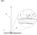
- a system is also in Fig. 5 shown schematically.
- Position (13) in Fig. 5 corresponds to the roller device according to the invention, which is mounted here at the front and rear end of the damper.
- the roller assembly must center the tube (8) in the magnetic damper, even with changing external radial forces. At the same time, an axial movement of the damper with minimal rolling resistance can be made possible in an advantageous manner.
Landscapes
- Engineering & Computer Science (AREA)
- General Engineering & Computer Science (AREA)
- Mechanical Engineering (AREA)
- Rolls And Other Rotary Bodies (AREA)
- Vibration Prevention Devices (AREA)
Description
- Die Erfindung betrifft eine selbstzentrierende Führung für entlang ihrer Längsachse bewegte Rohre, Stangen und Stäbe, wie sie in zahlreichen Maschinen und Vorrichtungen eingesetzt werden. Die Erfindung betrifft insbesondere eine selbstzentrierende Rollenführung mit deren Hilfe das besagte bewegte Teil über entlang seines Umfangs angeordnete Laufrollen, reibungsarm geführt werden kann, wobei die Laufrollen durch entsprechend konstruierte und angeordnete Spannvorrichtungen ihre Fähigkeit zur Selbstzentrierung erhalten.
Die Erfindung betrifft weiter Schwingungsdämpfer und Schwingungstilger, welche mit derartigen Rollenführungen ausgestattet sind. - In zahlreichen Maschinen und Vorrichtungen müssen Stangen mechanisch hin- und her bewegt werden. Dabei ist es oft unumgänglich diese Stangen an einem oder mehreren Punkten zu führen, was zu erhöhten Reibungseinflüssen führt. Üblicherweise werden für diese Zwecke im Stand der Technik unmittelbar Gleitlager oder Kugellager eingesetzt. Diese Lager können jedoch zu Problem führen, wenn während der Bewegung der Stange radiale Kräfte auf diese einwirken. Erhöhte Reibung und verringerte Haltbarkeit der Lager sind die Folge.
- Aus diesem Grund ist es sinnvoll in solchen Fällen Lager einzusetzen, welche derartige Belastungen und Kräfte berücksichtigen können.
- Es bestand somit die Aufgabe eine entsprechende Führung von sich hin- und her bewegenden Stangen und Rohren zur Verfügung zu stellen, welche nicht nur gewohnt reibungsarm ist, sondern auch in der Lage ist, insbesondere regelmäßig oder unregelmäßige transversale Kräfte auf die Stange oder das Rohr automatisch auszugleichen, und die Stange stets zentriert zu halten und zu führen.
- Die Aufgabe wurde durch die vorliegende Erfindung, wie sie in den Ansprüchen, der folgenden Beschreibung und der Abbildungen näher dargelegt ist, gelöst.
- Gegenstand der Erfindung ist somit eine selbstzentrierende Rollenvorrichtung zum reibungsarmen Führen von Rohren oder Stäben, welche in Richtung ihrer Längsachse bewegt werden, umfassend eine mit Laufrollen ausgestattete Spannvorrichtung, wobei die Laufrollen im Wesentlichen gleichmäßig entlang des Umfanges des zu führenden Rohres oder Stabes angeordnet, in Bewegungsrichtung ausgerichtet und in radialer Richtung federelastisch beweglich sind, wobei die Spannvorrichtung (6) einen ersten und einen zweiten Spannring (6a, 6b) aufweist, welche durch Federelemente (7) miteinander verbunden und gegeneinander verspannt sind, und der erste Spannring (6a) mit der ersten Hälfte einer vorzugsweise geradzahligen Anzahl von Laufrollen (1) aufweisenden ersten Rollenhalterungen (3a) über Abstandshülsen (10a) und der zweite Spannring (6b) mit der zweiten Hälfte von Laufrollen (1) aufweisenden Rollenhalterungen (3b) über Abstandshülsen (10b) verbunden ist, wobei jede der besagte Rollenhalterungen (3a, 3b) über eine parallel zum Rohr (8) angeordneten Achse (4) mit einer ringförmigen Trägervorrichtung (5) verbunden ist, durch deren konzentrische Öffnung besagtes Rohr (8) oder besagter Stab (8) berührungsfrei mittels der außerhalb der Trägervorrichtung (5) angeordneten Laufrollen (1) geführt und relativ zur Trägervorrichtung (5) bewegt wird.
- Hierbei umfasst die Rollenhalterung (3a, 3b) mindestens eine Laufrolle (1), welchen über eine Rollenachse (2) mit der Rollenhalterung befestigt ist, wobei die Rollenhalterung (3a, 3b) vorzugsweise mit der Achse (4) in der Weise verbunden ist, dass sie um diese radial bewegbar ist, um entsprechende Bewegungen der Vorrichtungen mitmachen zu können. Ferner ist die Rollenhalterung (3a, 3b) vorzugsweise mit der betreffenden Abstandshülse (10a, 10b) verbunden ist.
- Vorzugsweise ist der erste Spannring ein vorderer Spannring (6a) und der zweite Spannring ein hinterer Spannring (6b), ebenso wie die erste Rollenhaltung eine vordere Rollenhalterung (3a) und die zweite Rollenhalterung eine hintere Rollenhalterung (3b) ist. Dabei ist die vordere Rollenhalterung (3a) über die Abstandshülse (10a) mit der vorderen Spannvorrichtung (6a) verbunden, und die hintere Rollenhalterung (3b) über die Abstandshülse (10b) mit der hinteren Spannvorrichtung (6b) verbunden..
- Gegenstand ist ferner auch ein rotationsymmetrischer Magnetschwingungsdämpfer umfassend ein inneres Rohr und ein äußeres Rohr, wobei ein Rohr mit einer Trägervorrichtung fest verbunden ist und das andere Rohr innerhalb des ersten Rohres berührungslos bewegbar ist, wobei ein Rohr aus einem nicht magnetisierbaren leitfähigem Material (beispielsweise Aluminium, Kupfer) besteht, und das andere Rohr sich zusammensetzt aus einem oder mehreren permanentmagnetischen oder magnetisierbaren Ringen oder Ringsegmenten, wobei diese magnetischen oder magnetisierbaren Elemente so angeordnet sind, dass Nord- und Südpol entweder radial nach innen oder radial nach außen in Bezug auf die Längsachse oder des nicht-magnetisierbaren Rohrs weisen, wobei der besagte Dämpfer eine erfindungsgemäße selbstzentrierende Rollenvorrichtung wie folgend beschrieben, aufweist. Diese gewährleistet eine reibungsfreie relative Bewegung des nicht magnetischen leitfähigen Rohrs gegenüber den besagten magnetischen oder magnetisierbaren Rohrelementen.
- Gegenstand der Erfindung sind ferner Schwingungstilger, insbesondere für Windkraftanlagen, welche derartige erfindungsgemäße Rollenführungen aufweisen.
- Gegenstand sind letztlich auch Maschinen und Vorrichtungen, insbesondere Windkraftanlagen, welche eine erfindungsgemäße selbstzentrierende Rollenführung aufweisen.
- Im Folgenden und in den Ansprüchen wird auf folgende Referenzzeichen Bezug genommen:
- (1)
- Rolle
- (2)
- Rollen-Achse
- (3)
- Rollenhalterung
- (3a)
- Rollenhalterung (vorne)
- (3b)
- Rollenhalterung (hinten)
- (4)
- Achse für Laufrolleneinheit
- (5)
- Trägervorrichtung mit Befestigungsvorrichtung für Bauteil (4)
- (6)
- Spannvorrichtung
- (6a)
- vorderer Spannring der Spannvorrichtung
- (6b)
- hinterer Spannring der Spannvorrichtung
- (7)
- Federelement für Spannvorrichtung
- (8)
- hin- und her zu bewegendes Rohr / Stange
- (9)
- äußeres Rohr / Basisstruktur
- (10)
- Röhrchen / Abstandshülse
- (10a)
- Röhrchen / Abstandshülse (vorne)
- (10b)
- Röhrchen / Abstandshülse (hinen)
- (11)
- Langloch
- (12)
- Laufrolleneinheit umfassend Rolle (1), Achse (2) und Halterung (3)
- (13)
- selbstzentrierende Rollenvorrichtung umfassend Merkmale (1) bis (11)
- (14)
- Magnetringe
- (15)
- Pendel mit Pendelmasse
- 16)
- Magnetdämpfer
- (17)
- Verwindungssteifer Haltering
- Die erfindungsgemäße selbstzentrierende Rollenanordnung umfasst im Wesentlichen wie in
Abb. 1 undAbb. 4 dargestellt, eine im Wesentlichen ringförmige Spannvorrichtung (6), sowie eine Laufrollenkonstruktion, die miteinander verbunden sind. - Die Laufrollenkonstruktion wiederum umfasst eine vorzugsweise aber nicht notwendigerweise eine geradzahlige Anzahl von Laufrolleneinheiten (12), vorzugsweise mindestens 4, insbesondere 4, 6, 8, 10 oder 12.
- Jede Laufrolleneinheiten (12) umfasst wiederum mindestens eine, vorzugsweise eine Laufrolle (1) mit Laufrollenhalterungen (3), wobei die Laufrolle auf eine Rollenachse (2) gesteckt ist. Die Laufrollen können aus Kunststoff oder einem anderen üblichen Rollenwerkstoff (Aluminium, Stahl, Carbonfaser, etc.) bestehen und gegebenenfalls über ein oder mehrere Gleit- oder Kugellager verfügen.
- Die 4, 6, 8, 10 oder 12 Laufrolleneinheiten (12) sind radial um das zu zentrierende Rohr (8) angeordnet, und durch die Spannvorrichtung (6) so gegen das Rohr (8) gepresst, dass sie dieses zentrieren, ohne dass dabei die Reibung bei axialer Bewegung des Rohres hinderlich wird.
- Der Rollenhalterungen (3) sind drehbar/bewegbar auf Halterachsen (4) gesteckt, welche mit der vorzugsweise ringförmigen Trägerkonstruktion (5) verbunden sind.
- Die Trägerkonstruktion (5) ist mit einer entsprechenden Basisstruktur (9) fest verbunden. Die Basisstruktur kann eine beliebige Maschine oder Vorrichtung sein. In einer besonderen Ausführungsform der Erfindung ist die Basisstruktur ein Schwingungsdämpfer oder ein Teil eines Schwingungsdämpfers, insbesondere ein rotationssymmetrischer aus zwei ineinander gesteckten und relativ gegeneinander bewegbaren Rohren bestehender Magnetdämpfer. Dabei wird die ringförmige Trägerkonstruktion (5) mit dem Rohr (9) des Dämpfers fest verbunden, welcher in eine besonderen Ausführungsform ein Magnetrohr oder eine Rohr aus ringförmigen Magnetsegmenten ist (
Abb. 2 ). - Die Spannvorrichtung (6) umfasst erfindungsgemäß zwei Spannringe (6a, 6b), einen vorderen Spannring (6a) und einen hinteren Spannring (6b), die gegeneinander durch Federelemente (7) verspannt sind. Als Federelemente kommen Druck- oder Zugfedern in Frage, ggf. auch entsprechende Elastomerfedern. Anzahl und Federsteifigkeit richten sich nach Größe des Bauteils und Wert der angreifenden axialen Kraft. Die Federelemente (7) werden in Halterungen, Haken oder Ösen an den Spannringen (6) befestigt, bzw. eingehängt, und spannen diese vor.
- An jeder Rollenhalterung (3) ist eine Abstandshülse oder ein Röhrchen (10) angeschraubt oder anderweitig fest angebracht, welche(s) wiederum mit der Spannvorrichtung (6) verbunden ist.
- In
Abb. 3a und 3b ist im Detail dargestellt, wie erfindungsgemäß die Rolleneinheiten (12) mit den Spannvorrichtungen (6a)(6b) verbunden sind:
Dabei ist erfindungsgemäß die Hälfte der Laufrolleneinheiten (12), bestehend aus Laufrolle (1), Rollenachse (2) und Rollenhalterung (3), mit ein und demselben der beiden Spannringe (6), vorzugsweise dem vorderen (6a) oder dem hinteren (6b) Spannring verbunden, während die andere Hälfte mit dem anderen der beiden Spannringringe (6), vorzugsweise den hinteren (6b) oder dem vorderen (6a) verbunden ist. Somit sind die Rollenhalterungen (3a) (und damit auch die entsprechenden Laufrollen (1)) über die Abstandshülsen/die Röhrchen (10a) mit dem vorderen Spannring (6a) verbunden, während die Rollenhalterungen (3b) mit den entsprechenden Laufrollen (1) über die Abstandshülsen /die Röhrchen (10b) mit dem hinteren Spannring (6b) verbunden sind. Aus Kräfte-Symmetriegründen wechseln sich vorzugsweise Laufrolleneinheiten (12) gemäß (1, 2, 3a, 10a), welche mit dem vorderen Ring (6a) der Spannvorrichtung (6) verbunden sind, mit Laufrolleneinheiten (12) gemäß (1, 2, 3b, 10b), welche mit dem hinteren Spannring (6b) verbunden sind, ab. Somit ist also jede zweite Laufrollenvorrichtung (12) mit dem gleichen Spannring (6a) oder (6b) verbunden. - Damit die Federkräfte und durch sie initiierte Bewegungen der Laufrolleneinheiten (12), insbesondere der Abstandshülsen (10a, 10b) in radialer Richtung wirksam werden können und gleichzeitig die tangentiale umlaufende Kraft übertragen werden kann, befinden sich Langlöcher (11) an den betreffenden Positionen der Spannringe (6a) (6b). Somit ist genügend Platz für vorgesehenen Bewegungen der Laufrollenkonstruktion in radialer Richtung. Dazu gehört auch, dass sich die Rollenhalterungen auf den Achsen (4) bewegen können.
- Eine weitere Ausführungsform der Erfindungsgemäßen Rollenführung ist in
Abb. 3c dargestellt. Hierbei ist ein metallener steifer Ring (17) entlang der Rolleneinheiten angebracht, um bei besonderen Belastungen die Konstruktion verwindungssteif zu machen. - Die erfindungsgemäße Rollenvorrichtung funktioniert auf folgende Weise:
Die Federelemente (7) spannen die beiden Spannringe (6a) (6b) vor und sorgen dafür, dass alle Laufrollen (1) mit der gleichen Kraft an das zu zentrierende Rohr 8 gepresst werden. Eine externe radiale Kraft auf das zu zentrierende bewegte Rohr (8) führt dazu, dass die Laufrollen (1) in Kraftrichtung etwas einfedern und die gegenüberliegenden Laufrollen (1) dadurch mit geringerer Kraft anliegen. Die Anpresskraft auf die Rollen (1) in Kraftrichtung steigt somit. Die beiden Spannringe (6a) (6b) der Spannvorrichtung (6) werden so zueinander verschoben und die Kräfte in den Federelementen (7) steigen und fallen von Federelement zu Federelement. Wird die externe Kraft entfernt, gleichen sich die Federkräfte wieder an und das Rohr (8) wird wieder vollständig zentriert. Die Vorspannkraft für die einzelnen Laufrollen (1) hängt dabei von der Anzahl und den Vorspannkräften der einzelnen Federelemente (7) ab. Die gesamte radiale Steifigkeit der Rollenanordnung hängt weiterhin von der Anzahl und der Steifigkeit der einzelnen Federelemente (7) ab. Je nach Notwendigkeit können mehr oder weniger Federelemente (7) verwendet werden, wodurch ebenfalls Einfluss auf die Steifigkeit und somit auf die Zentrierung genommen werden kann. - Die erfindungsgemäße selbstzentrierende Rollenanordnung macht ein manuelles Ausrichten und Vorspannen der einzelnen Laufrollen (1) überflüssig. Die Rollen (1) werden gleichmäßig an das Laufrohr oder die Laufstange (8), wodurch sich automatisch eine Zentrierung einstellt.
- Bei einer Temperaturerhöhung dehnt sich das Rohr / die Stange (8) aus (z. B. bei einem Aluminium Rohr oder Stab), und auch der Durchmesser der Laufrollen (1) (z.B. aus Kunststoff) wird ebenfalls größer. Eine fest eingestellte Laufrolle (1) würde hierfür eine starke Änderung der Vorspannkraft auf die Rollen (1) führen, was wiederum in nicht gewünschter Weise das Rohr (8) belastet. Bei einer Temperatursenkung hingegen ziehen sich das Rohr und die Rollen zusammen. Bei einer fest eingestellten Laufrolle sinkt somit die Vorspannkraft und es kann sogar zu einem Kontaktverlust und damit zu einem Verlust der Zentrierung führen. Mit der selbstzentrierende Rollenanordnung sind die Änderungen der Vorspannkraft minimal und gleichzeitig wird die Zentrierung gewährleistet da es zu keinem Kontaktverlust kommt.
- Die selbstzentrierende Rollenanordnung lässt sich einfach vormontieren (siehe
Abb.4 ). Die Federelemente (7) (hier Zug-Spiralfedern) können beinahe kraftfrei in die Ösen der Spannringe (6a) (6b) eingehängt werden. Dabei ragen alle Laufrollen (1) weiter in Richtung Mittelpunkt der Rollenanordnung. Sobald alle Federn eingehängt wurden, kann die ringförmige Trägervorrichtung (5) der erfindungsgemäßen Rollenanordnung mit dem Basisstruktur (9) verschraubt werden. Ein Ende des Rohrs oder Stabes (8) kann mit einem ansteigenden Konus mit geringer Steigung versehen sein, so dass beim Aufschieben des Basisstruktur (beispielsweise ein Schwingungsdämpfer) über den Konus die Laufrollen (1) immer weiter nach außen gedrückt und dabei die Federelemente (7) gespannt werden. Gleichzeitig wird das Rohr (8) schon während des Aufschiebens zentriert. Die Federelemente (7) sind nun auf die volle Zugkraft vorgespannt. - Die Erfindungsgemäße selbstzentrierende Rollenvorrichtung ist insbesondere geeignet, in Schwingungsdämpfern, vorzugsweise in rotationssymmetrischen Magnetdämpfern eingesetzt zu werden, da hier ein nicht magnetisches, nicht magnetisierbares leitendes metallisches Rohr (z.B. aus Aluminium oder Kupfer) innerhalb eines magnetischen Rohrs (Permanentmagnete oder magnetisierbare Spulen) oder einer entsprechenden magnetischen ringförmigen Anordnung relativ bewegt wird, wodurch eine magnetische Dämpfung erzielt wird. Somit kann ein mit dem Dämpfer verbundenes Schwingungssystem gedämpft werden, beispielsweise ein schwingendes Pendel eines Schwingungstilgers.
- Ein entsprechender Magnetschwingungstilger ist beispielsweise in der
WO 2016/023628 im Detail beschrieben, einem Dokument, dass unter Artikel 54(3) EPÜ fällt. - Ein solches System ist auch in
Abb. 5 schematisch dargestellt. Position (13) inAbb. 5 entspricht der erfindungsgemäßen Rollenvorrichtung, welche hier am vorderen und hinteren Ende des Dämpfers montiert ist. Die Rollenanordnung muss das Rohr (8) im Magnetdämpfer zentrieren, auch bei sich ändernden externen radialen Kräften. Gleichzeitig kann in vorteilhafter Weise eine axiale Bewegung des Dämpfers mit minimalen Rollwiderständen ermöglicht werden.
Claims (15)
- Selbstzentrierende Rollenvorrichtung zum reibungsarmen Führen von Rohren oder Stäben (8), welche in Richtung ihrer Längsachse bewegt werden, umfassend eine mit einer Anzahl von Laufrolleneinheiten (12) ausgestatteten Spannvorrichtung (6), wobei die Laufrolleneinheiten (12) im Wesentlichen gleichmäßig entlang des Umfanges des zu führenden Rohres oder Stabes (8) angeordnet, in Bewegungsrichtung ausgerichtet und in radialer Richtung federelastisch beweglich sind,
dadurch gekennzeichnet, dass die Spannvorrichtung (6) einen vorderen und einen hinteren Spannring (6a, 6b) aufweist, welche durch Federelemente (7) miteinander verbunden und gegeneinander verspannt sind, wobei der vordere Spannring (6a) mit der ersten Hälfte der Anzahl von Laufrolleneinheiten (12) über Abstandshülsen (10a) und der hintere Spannring (6b) mit der zweiten Hälfte der Anzahl der Laufrolleneinheiten (12) über Abstandshülsen (10b) verbunden ist, wobei jede der besagten Laufrolleneinheiten über eine parallel zum Rohr (8) angeordneten Achse (4) mit einer ringförmigen Trägervorrichtung (5) verbunden ist, durch deren konzentrische Öffnung besagtes Rohr (8) oder besagter Stab (8) berührungsfrei mittels der außerhalb der Trägervorrichtung (5) angeordneten Laufrolleneinheiten (12) geführt und relativ zur Trägervorrichtung (5) bewegt wird. - Selbstzentrierende Rollenvorrichtung nach Anspruch 1, dadurch gekennzeichnet, dass jede Laufrolleneinheit (12) eine vordere Rollenhalterung (3a) und eine hintere Rollenhalterung (3b) und mindestens eine Laufrolle (1) umfasst, welche über eine Rollenachse (2) mit der betreffenden Rollenhalterung befestigt ist, und die Rollenhalterung (3a, 3b) mit der Achse (4) verbunden ist, und um diese radial bewegbar ist.
- Selbstzentrierende Rollenvorrichtung nach Anspruch 2, dadurch gekennzeichnet, dass die vordere Rollenhalterung (3a) mittels der Abstandshülsen (10a) mit dem vorderen Spannring (6a), und die hintere Rollenhalterung (3b) mittels der Abstandshülsen (10b) mit dem hinteren Spannring (10b) verbunden ist.
- Selbstzentrierende Rollenvorrichtung nach Anspruch 2 oder 3, dadurch gekennzeichnet, dass die Laufrolleneinheiten (12) so um das Rohr (8) herum angeordnet sind, dass sie abwechselnd mit dem vorderen (6a) und dem hinteren (6b) Spannring verbunden sind.
- Selbstzentrierende Rollenvorrichtung nach einem der Ansprüche 1 - 4, dadurch gekennzeichnet, dass die Spannringe (6a, 6b) im Wesentlichen radial angeordnete Langlöcher (11a, 11b) aufweisen, mit denen die Abstandshülsen (10a, 10b) und damit an diese befestigte Laufrolleneinheiten (12) in der Weise verbunden sind, dass sie sich in den Langlöchern (11a, 11b) bewegen können, entsprechend der über das Rohr (8) und die Laurollen (1) vermittelten einwirkenden Kräfte.
- Selbstzentrierende Rollenvorrichtung nach einem der Ansprüche 1 - 5, dadurch gekennzeichnet, dass alle Laufrolleneinheiten (12) auf einer Seite der Spannvorrichtung (6) angeordnet sind, wobei der vordere Spannring (6a) Öffnungen aufweist, durch welche die Abstandshülsen (10b), zu dem hinteren Spannring (6b) geführt werden.
- Selbstzentrierende Rollenvorrichtung nach einem der Ansprüche 1 - 6, dadurch gekennzeichnet, dass sie vier, sechs, acht, zehn oder zwölf Laufrolleneinheiten (12) aufweist.
- Selbstzentrierende Rollenvorrichtung nach einem der Ansprüche 1 - 7, dadurch gekennzeichnet, dass die Federelemente (7) Druck-, oder Zugfedern, oder Elastomerfedern sind.
- Selbstzentrierende Rollenvorrichtung nach einem der Ansprüche 1 - 8, dadurch gekennzeichnet, dass die Spannringe (6a, 6b) Haken oder Ösen haben, in denen die Federelemente (7) eingehängt sind.
- Selbstzentrierende Rollenvorrichtung nach einem der Ansprüche 1-9, dadurch gekennzeichnet, dass die vordere und / oder hintere Rollenhalterung (3a) (3b) einen festen Ring aufweist, der die jeweiligen Rollenhalterungen miteinander verbindet und die Vorrichtung verwindungssteif macht.
- Rotationssymmetrischer Magnetschwingungsdämpfer dadurch gekennzeichnet, dass er eine selbstzentrierende Rollenvorrichtung gemäß einem der Ansprüche 1 - 10 aufweist.
- Rotationsymmetrischer Magnetschwingungsdämpfer nach Anspruch 11 ferner umfassend ein inneres Rohr und ein äußeres Rohr, wobei das eine Rohr mit einer Trägervorrichtung fest verbunden ist und das andere Rohr innerhalb des ersten Rohres berührungslos bewegbar ist, und das eine Rohr aus einem nicht magnetisierbaren leitfähigem Material besteht, während das andere Rohr sich zusammensetzt aus einem oder mehreren permanentmagnetischen oder magnetisierbaren Ringen oder Ringsegmenten (14), wobei diese magnetischen oder magnetisierbaren Elemente so angeordnet sind, dass Nord- und Südpol entweder radial nach innen oder radial nach außen in Bezug auf die Längsachse oder des nicht-magnetisierbaren Rohrs weisen, wobei die selbstzentrierende Rollenvorrichtung eine reibungsfreie relative Bewegung des nicht magnetischen leitfähigen Rohrs gegenüber den besagten magnetischen oder magnetisierbaren Rohrelementen gewährleistet.
- Rotationssymmetrischer Magnetschwingungsdämpfer nach Anspruch 12, dadurch gekennzeichnet, dass die Trägervorrichtung (5) mit dem äußeren Rohr (9) fest verbunden ist, und das innere Rohr (8) durch die Rollenvorrichtung gegenüber dem äußeren Rohr (9) bewegt wird.
- Rotationssymmetrischer Magnetschwingungsdämpfer nach einem der Ansprüche 11 - 13, dadurch gekennzeichnet, dass besagte Rollenvorrichtung vor und / oder hinter dem funktionellen Bereich des Magnetdämpfers angebracht ist.
- Schwingungstilger umfassend mindestens ein Pendelseil oder eine Pendelstange mit einer Pendelmasse (15) und mindestens zwei rotationssymmetrischen Magnetdämpfern gemäß einem der Ansprüche 11 - 14.
Applications Claiming Priority (2)
| Application Number | Priority Date | Filing Date | Title |
|---|---|---|---|
| EP15003273 | 2015-11-17 | ||
| PCT/EP2016/001873 WO2017084747A1 (de) | 2015-11-17 | 2016-11-10 | Selbstzentrierende rollenführung |
Publications (2)
| Publication Number | Publication Date |
|---|---|
| EP3377781A1 EP3377781A1 (de) | 2018-09-26 |
| EP3377781B1 true EP3377781B1 (de) | 2019-10-09 |
Family
ID=54695430
Family Applications (1)
| Application Number | Title | Priority Date | Filing Date |
|---|---|---|---|
| EP16801962.8A Active EP3377781B1 (de) | 2015-11-17 | 2016-11-10 | Selbstzentrierende rollenführung |
Country Status (5)
| Country | Link |
|---|---|
| EP (1) | EP3377781B1 (de) |
| DK (1) | DK3377781T3 (de) |
| ES (1) | ES2764469T3 (de) |
| PT (1) | PT3377781T (de) |
| WO (1) | WO2017084747A1 (de) |
Families Citing this family (2)
| Publication number | Priority date | Publication date | Assignee | Title |
|---|---|---|---|---|
| WO2019185196A1 (de) | 2018-03-30 | 2019-10-03 | Esm Energie- Und Schwingungstechnik Mitsch Gmbh | Lineare magnetfeder und verwendung in schwingungstilgern |
| CN110565936B (zh) * | 2019-08-30 | 2021-07-06 | 广东博智林机器人有限公司 | 调谐质量阻尼器装置和具有其的悬吊建筑机器人 |
Family Cites Families (5)
| Publication number | Priority date | Publication date | Assignee | Title |
|---|---|---|---|---|
| US3003739A (en) * | 1959-10-14 | 1961-10-10 | United Carr Fastener Corp | Vibration isolator |
| DE102008004565A1 (de) * | 2008-01-15 | 2009-07-23 | Ab Skf | Aktiv gedämpfter Lageranordnung |
| CA2806877A1 (en) * | 2010-07-29 | 2012-02-02 | Lei ZUO | Electricity generating shock absorbers |
| AT512682B1 (de) * | 2012-03-29 | 2015-03-15 | Siemens Vai Metals Tech Gmbh | Strangführungselement |
| BR112017002477A2 (pt) | 2014-08-13 | 2017-12-05 | Esm Energie Und Schwingungstechnik Mitsch Gmbh | amortecedor magnético para absorvedores de vibração |
-
2016
- 2016-11-10 ES ES16801962T patent/ES2764469T3/es active Active
- 2016-11-10 EP EP16801962.8A patent/EP3377781B1/de active Active
- 2016-11-10 DK DK16801962.8T patent/DK3377781T3/da active
- 2016-11-10 PT PT168019628T patent/PT3377781T/pt unknown
- 2016-11-10 WO PCT/EP2016/001873 patent/WO2017084747A1/de not_active Ceased
Non-Patent Citations (1)
| Title |
|---|
| None * |
Also Published As
| Publication number | Publication date |
|---|---|
| EP3377781A1 (de) | 2018-09-26 |
| ES2764469T3 (es) | 2020-06-03 |
| WO2017084747A1 (de) | 2017-05-26 |
| PT3377781T (pt) | 2019-12-18 |
| DK3377781T3 (da) | 2020-01-20 |
Similar Documents
| Publication | Publication Date | Title |
|---|---|---|
| EP3180542B1 (de) | Magnetdämpfer für schwingungstilger | |
| EP0512154A1 (de) | Zentriereinrichtung für Bohr- und Futterrohre " | |
| DE19960699A1 (de) | Federbeinlagerung | |
| DE102015112099A1 (de) | Federsitz aus Kunststoff mit integriertem Crashelement | |
| WO2015036199A1 (de) | Lagervorrichtung einer querblattfeder, die im bereich einer fahrzeugachse eines fahrzeuges montierbar ist | |
| WO2015154761A1 (de) | Segmentlageranordnung mit formschlüssig gesichertem kunststoffkäfig | |
| DE1946142A1 (de) | Magnetische Untersuchungsvorrichtung fuer Rohre | |
| EP0058911A1 (de) | Gummifeder für die elastische Lagerung von Maschinen | |
| DE102013101671B4 (de) | Adaptiver Drehschwingungstilger mit einer über Blattfedern an einer Nabe elastisch gelagerten ringförmigen Tilgermasse | |
| WO2016050713A1 (de) | Lagerkäfigsegment, wälzlager und assemblierungsverfahren | |
| DE102014106587A1 (de) | Wälzlager, insbesondere Vierpunktlager oder Doppelvierpunktslager für Windkraftanlagen | |
| DE102017212276A1 (de) | Hauptspindelvorrichtung einer Werkzeugmaschine | |
| EP1710894A1 (de) | Elektrische Maschine | |
| EP3377781A1 (de) | Selbstzentrierende rollenführung | |
| WO2014135144A1 (de) | Torsionsschwingungsdämpfer mit zumindest einer primärseite und einer sekundärseite | |
| EP2895756B1 (de) | Wälzlager | |
| DE102011006326A1 (de) | Wälzlager | |
| DE2934710C2 (de) | Rotor zur Drehenergiespeicherung | |
| DE102014224700B3 (de) | Federbeinlager | |
| WO2014194899A1 (de) | Lageranordnung mit einem fanglager | |
| DE102010054902A1 (de) | Mehrteiliges Wälzlager | |
| EP2491262B1 (de) | Supraleitendes lager und verfahren zu dessen montage | |
| DE102017202938A1 (de) | Dämpfung eines Lenkeinschlags bei einem Fahrrad | |
| DE102017006865A1 (de) | Aufspulmaschine | |
| DE102017005503A1 (de) | Wälzlager sowie Kraftfahrzeug |
Legal Events
| Date | Code | Title | Description |
|---|---|---|---|
| STAA | Information on the status of an ep patent application or granted ep patent |
Free format text: STATUS: UNKNOWN |
|
| STAA | Information on the status of an ep patent application or granted ep patent |
Free format text: STATUS: THE INTERNATIONAL PUBLICATION HAS BEEN MADE |
|
| PUAI | Public reference made under article 153(3) epc to a published international application that has entered the european phase |
Free format text: ORIGINAL CODE: 0009012 |
|
| STAA | Information on the status of an ep patent application or granted ep patent |
Free format text: STATUS: REQUEST FOR EXAMINATION WAS MADE |
|
| 17P | Request for examination filed |
Effective date: 20180522 |
|
| AK | Designated contracting states |
Kind code of ref document: A1 Designated state(s): AL AT BE BG CH CY CZ DE DK EE ES FI FR GB GR HR HU IE IS IT LI LT LU LV MC MK MT NL NO PL PT RO RS SE SI SK SM TR |
|
| AX | Request for extension of the european patent |
Extension state: BA ME |
|
| DAV | Request for validation of the european patent (deleted) | ||
| DAX | Request for extension of the european patent (deleted) | ||
| RIC1 | Information provided on ipc code assigned before grant |
Ipc: F16F 7/10 20060101ALI20190321BHEP Ipc: F16F 6/00 20060101ALI20190321BHEP Ipc: F16C 29/12 20060101ALI20190321BHEP Ipc: F16C 29/04 20060101AFI20190321BHEP |
|
| GRAP | Despatch of communication of intention to grant a patent |
Free format text: ORIGINAL CODE: EPIDOSNIGR1 |
|
| STAA | Information on the status of an ep patent application or granted ep patent |
Free format text: STATUS: GRANT OF PATENT IS INTENDED |
|
| INTG | Intention to grant announced |
Effective date: 20190426 |
|
| GRAS | Grant fee paid |
Free format text: ORIGINAL CODE: EPIDOSNIGR3 |
|
| GRAA | (expected) grant |
Free format text: ORIGINAL CODE: 0009210 |
|
| STAA | Information on the status of an ep patent application or granted ep patent |
Free format text: STATUS: THE PATENT HAS BEEN GRANTED |
|
| AK | Designated contracting states |
Kind code of ref document: B1 Designated state(s): AL AT BE BG CH CY CZ DE DK EE ES FI FR GB GR HR HU IE IS IT LI LT LU LV MC MK MT NL NO PL PT RO RS SE SI SK SM TR |
|
| REG | Reference to a national code |
Ref country code: GB Ref legal event code: FG4D Free format text: NOT ENGLISH |
|
| REG | Reference to a national code |
Ref country code: CH Ref legal event code: EP |
|
| REG | Reference to a national code |
Ref country code: IE Ref legal event code: FG4D Free format text: LANGUAGE OF EP DOCUMENT: GERMAN |
|
| REG | Reference to a national code |
Ref country code: DE Ref legal event code: R096 Ref document number: 502016007065 Country of ref document: DE |
|
| REG | Reference to a national code |
Ref country code: AT Ref legal event code: REF Ref document number: 1189178 Country of ref document: AT Kind code of ref document: T Effective date: 20191115 |
|
| REG | Reference to a national code |
Ref country code: PT Ref legal event code: SC4A Ref document number: 3377781 Country of ref document: PT Date of ref document: 20191218 Kind code of ref document: T Free format text: AVAILABILITY OF NATIONAL TRANSLATION Effective date: 20191210 |
|
| REG | Reference to a national code |
Ref country code: CH Ref legal event code: NV Representative=s name: BOVARD AG PATENT- UND MARKENANWAELTE, CH |
|
| REG | Reference to a national code |
Ref country code: DK Ref legal event code: T3 Effective date: 20200114 |
|
| PGFP | Annual fee paid to national office [announced via postgrant information from national office to epo] |
Ref country code: PT Payment date: 20191216 Year of fee payment: 4 |
|
| REG | Reference to a national code |
Ref country code: NL Ref legal event code: MP Effective date: 20191009 |
|
| REG | Reference to a national code |
Ref country code: LT Ref legal event code: MG4D |
|
| PG25 | Lapsed in a contracting state [announced via postgrant information from national office to epo] |
Ref country code: GR Free format text: LAPSE BECAUSE OF FAILURE TO SUBMIT A TRANSLATION OF THE DESCRIPTION OR TO PAY THE FEE WITHIN THE PRESCRIBED TIME-LIMIT Effective date: 20200110 Ref country code: BG Free format text: LAPSE BECAUSE OF FAILURE TO SUBMIT A TRANSLATION OF THE DESCRIPTION OR TO PAY THE FEE WITHIN THE PRESCRIBED TIME-LIMIT Effective date: 20200109 Ref country code: FI Free format text: LAPSE BECAUSE OF FAILURE TO SUBMIT A TRANSLATION OF THE DESCRIPTION OR TO PAY THE FEE WITHIN THE PRESCRIBED TIME-LIMIT Effective date: 20191009 Ref country code: LT Free format text: LAPSE BECAUSE OF FAILURE TO SUBMIT A TRANSLATION OF THE DESCRIPTION OR TO PAY THE FEE WITHIN THE PRESCRIBED TIME-LIMIT Effective date: 20191009 Ref country code: LV Free format text: LAPSE BECAUSE OF FAILURE TO SUBMIT A TRANSLATION OF THE DESCRIPTION OR TO PAY THE FEE WITHIN THE PRESCRIBED TIME-LIMIT Effective date: 20191009 Ref country code: SE Free format text: LAPSE BECAUSE OF FAILURE TO SUBMIT A TRANSLATION OF THE DESCRIPTION OR TO PAY THE FEE WITHIN THE PRESCRIBED TIME-LIMIT Effective date: 20191009 Ref country code: NL Free format text: LAPSE BECAUSE OF FAILURE TO SUBMIT A TRANSLATION OF THE DESCRIPTION OR TO PAY THE FEE WITHIN THE PRESCRIBED TIME-LIMIT Effective date: 20191009 Ref country code: NO Free format text: LAPSE BECAUSE OF FAILURE TO SUBMIT A TRANSLATION OF THE DESCRIPTION OR TO PAY THE FEE WITHIN THE PRESCRIBED TIME-LIMIT Effective date: 20200109 Ref country code: PL Free format text: LAPSE BECAUSE OF FAILURE TO SUBMIT A TRANSLATION OF THE DESCRIPTION OR TO PAY THE FEE WITHIN THE PRESCRIBED TIME-LIMIT Effective date: 20191009 |
|
| PG25 | Lapsed in a contracting state [announced via postgrant information from national office to epo] |
Ref country code: HR Free format text: LAPSE BECAUSE OF FAILURE TO SUBMIT A TRANSLATION OF THE DESCRIPTION OR TO PAY THE FEE WITHIN THE PRESCRIBED TIME-LIMIT Effective date: 20191009 Ref country code: RS Free format text: LAPSE BECAUSE OF FAILURE TO SUBMIT A TRANSLATION OF THE DESCRIPTION OR TO PAY THE FEE WITHIN THE PRESCRIBED TIME-LIMIT Effective date: 20191009 Ref country code: IS Free format text: LAPSE BECAUSE OF FAILURE TO SUBMIT A TRANSLATION OF THE DESCRIPTION OR TO PAY THE FEE WITHIN THE PRESCRIBED TIME-LIMIT Effective date: 20200224 |
|
| REG | Reference to a national code |
Ref country code: ES Ref legal event code: FG2A Ref document number: 2764469 Country of ref document: ES Kind code of ref document: T3 Effective date: 20200603 |
|
| PG25 | Lapsed in a contracting state [announced via postgrant information from national office to epo] |
Ref country code: AL Free format text: LAPSE BECAUSE OF FAILURE TO SUBMIT A TRANSLATION OF THE DESCRIPTION OR TO PAY THE FEE WITHIN THE PRESCRIBED TIME-LIMIT Effective date: 20191009 |
|
| REG | Reference to a national code |
Ref country code: DE Ref legal event code: R097 Ref document number: 502016007065 Country of ref document: DE |
|
| PG2D | Information on lapse in contracting state deleted |
Ref country code: IS |
|
| PG25 | Lapsed in a contracting state [announced via postgrant information from national office to epo] |
Ref country code: EE Free format text: LAPSE BECAUSE OF FAILURE TO SUBMIT A TRANSLATION OF THE DESCRIPTION OR TO PAY THE FEE WITHIN THE PRESCRIBED TIME-LIMIT Effective date: 20191009 Ref country code: RO Free format text: LAPSE BECAUSE OF FAILURE TO SUBMIT A TRANSLATION OF THE DESCRIPTION OR TO PAY THE FEE WITHIN THE PRESCRIBED TIME-LIMIT Effective date: 20191009 Ref country code: CZ Free format text: LAPSE BECAUSE OF FAILURE TO SUBMIT A TRANSLATION OF THE DESCRIPTION OR TO PAY THE FEE WITHIN THE PRESCRIBED TIME-LIMIT Effective date: 20191009 Ref country code: MC Free format text: LAPSE BECAUSE OF FAILURE TO SUBMIT A TRANSLATION OF THE DESCRIPTION OR TO PAY THE FEE WITHIN THE PRESCRIBED TIME-LIMIT Effective date: 20191009 Ref country code: LU Free format text: LAPSE BECAUSE OF NON-PAYMENT OF DUE FEES Effective date: 20191110 Ref country code: IS Free format text: LAPSE BECAUSE OF FAILURE TO SUBMIT A TRANSLATION OF THE DESCRIPTION OR TO PAY THE FEE WITHIN THE PRESCRIBED TIME-LIMIT Effective date: 20200209 |
|
| PLBE | No opposition filed within time limit |
Free format text: ORIGINAL CODE: 0009261 |
|
| STAA | Information on the status of an ep patent application or granted ep patent |
Free format text: STATUS: NO OPPOSITION FILED WITHIN TIME LIMIT |
|
| REG | Reference to a national code |
Ref country code: BE Ref legal event code: MM Effective date: 20191130 |
|
| PG25 | Lapsed in a contracting state [announced via postgrant information from national office to epo] |
Ref country code: SK Free format text: LAPSE BECAUSE OF FAILURE TO SUBMIT A TRANSLATION OF THE DESCRIPTION OR TO PAY THE FEE WITHIN THE PRESCRIBED TIME-LIMIT Effective date: 20191009 Ref country code: SM Free format text: LAPSE BECAUSE OF FAILURE TO SUBMIT A TRANSLATION OF THE DESCRIPTION OR TO PAY THE FEE WITHIN THE PRESCRIBED TIME-LIMIT Effective date: 20191009 Ref country code: IT Free format text: LAPSE BECAUSE OF FAILURE TO SUBMIT A TRANSLATION OF THE DESCRIPTION OR TO PAY THE FEE WITHIN THE PRESCRIBED TIME-LIMIT Effective date: 20191009 |
|
| 26N | No opposition filed |
Effective date: 20200710 |
|
| PG25 | Lapsed in a contracting state [announced via postgrant information from national office to epo] |
Ref country code: IE Free format text: LAPSE BECAUSE OF NON-PAYMENT OF DUE FEES Effective date: 20191110 |
|
| PG25 | Lapsed in a contracting state [announced via postgrant information from national office to epo] |
Ref country code: BE Free format text: LAPSE BECAUSE OF NON-PAYMENT OF DUE FEES Effective date: 20191130 Ref country code: SI Free format text: LAPSE BECAUSE OF FAILURE TO SUBMIT A TRANSLATION OF THE DESCRIPTION OR TO PAY THE FEE WITHIN THE PRESCRIBED TIME-LIMIT Effective date: 20191009 |
|
| PGFP | Annual fee paid to national office [announced via postgrant information from national office to epo] |
Ref country code: TR Payment date: 20201104 Year of fee payment: 5 |
|
| PG25 | Lapsed in a contracting state [announced via postgrant information from national office to epo] |
Ref country code: CY Free format text: LAPSE BECAUSE OF FAILURE TO SUBMIT A TRANSLATION OF THE DESCRIPTION OR TO PAY THE FEE WITHIN THE PRESCRIBED TIME-LIMIT Effective date: 20191009 |
|
| PG25 | Lapsed in a contracting state [announced via postgrant information from national office to epo] |
Ref country code: HU Free format text: LAPSE BECAUSE OF FAILURE TO SUBMIT A TRANSLATION OF THE DESCRIPTION OR TO PAY THE FEE WITHIN THE PRESCRIBED TIME-LIMIT; INVALID AB INITIO Effective date: 20161110 Ref country code: MT Free format text: LAPSE BECAUSE OF FAILURE TO SUBMIT A TRANSLATION OF THE DESCRIPTION OR TO PAY THE FEE WITHIN THE PRESCRIBED TIME-LIMIT Effective date: 20191009 |
|
| PG25 | Lapsed in a contracting state [announced via postgrant information from national office to epo] |
Ref country code: PT Free format text: LAPSE BECAUSE OF NON-PAYMENT OF DUE FEES Effective date: 20210810 |
|
| PG25 | Lapsed in a contracting state [announced via postgrant information from national office to epo] |
Ref country code: MK Free format text: LAPSE BECAUSE OF FAILURE TO SUBMIT A TRANSLATION OF THE DESCRIPTION OR TO PAY THE FEE WITHIN THE PRESCRIBED TIME-LIMIT Effective date: 20191009 |
|
| PG25 | Lapsed in a contracting state [announced via postgrant information from national office to epo] |
Ref country code: TR Free format text: LAPSE BECAUSE OF NON-PAYMENT OF DUE FEES Effective date: 20211110 |
|
| PGFP | Annual fee paid to national office [announced via postgrant information from national office to epo] |
Ref country code: AT Payment date: 20241128 Year of fee payment: 9 |
|
| PGFP | Annual fee paid to national office [announced via postgrant information from national office to epo] |
Ref country code: CH Payment date: 20241201 Year of fee payment: 9 |
|
| PGFP | Annual fee paid to national office [announced via postgrant information from national office to epo] |
Ref country code: GB Payment date: 20251001 Year of fee payment: 10 |
|
| PGFP | Annual fee paid to national office [announced via postgrant information from national office to epo] |
Ref country code: DK Payment date: 20251125 Year of fee payment: 10 |
|
| PGFP | Annual fee paid to national office [announced via postgrant information from national office to epo] |
Ref country code: FR Payment date: 20251028 Year of fee payment: 10 |
|
| PGFP | Annual fee paid to national office [announced via postgrant information from national office to epo] |
Ref country code: ES Payment date: 20251201 Year of fee payment: 10 |
|
| PGFP | Annual fee paid to national office [announced via postgrant information from national office to epo] |
Ref country code: DE Payment date: 20260123 Year of fee payment: 10 |