EP3377397B1 - Vehicle for transporting a load - Google Patents
Vehicle for transporting a load Download PDFInfo
- Publication number
- EP3377397B1 EP3377397B1 EP16797913.7A EP16797913A EP3377397B1 EP 3377397 B1 EP3377397 B1 EP 3377397B1 EP 16797913 A EP16797913 A EP 16797913A EP 3377397 B1 EP3377397 B1 EP 3377397B1
- Authority
- EP
- European Patent Office
- Prior art keywords
- load
- fixing system
- chassis
- transport vehicle
- pallet
- Prior art date
- Legal status (The legal status is an assumption and is not a legal conclusion. Google has not performed a legal analysis and makes no representation as to the accuracy of the status listed.)
- Active
Links
Images


Classifications
-
- B—PERFORMING OPERATIONS; TRANSPORTING
- B62—LAND VEHICLES FOR TRAVELLING OTHERWISE THAN ON RAILS
- B62K—CYCLES; CYCLE FRAMES; CYCLE STEERING DEVICES; RIDER-OPERATED TERMINAL CONTROLS SPECIALLY ADAPTED FOR CYCLES; CYCLE AXLE SUSPENSIONS; CYCLE SIDE-CARS, FORECARS, OR THE LIKE
- B62K27/00—Sidecars; Forecars; Trailers or the like specially adapted to be attached to cycles
- B62K27/003—Trailers
-
- B—PERFORMING OPERATIONS; TRANSPORTING
- B62—LAND VEHICLES FOR TRAVELLING OTHERWISE THAN ON RAILS
- B62K—CYCLES; CYCLE FRAMES; CYCLE STEERING DEVICES; RIDER-OPERATED TERMINAL CONTROLS SPECIALLY ADAPTED FOR CYCLES; CYCLE AXLE SUSPENSIONS; CYCLE SIDE-CARS, FORECARS, OR THE LIKE
- B62K5/00—Cycles with handlebars, equipped with three or more main road wheels
- B62K5/02—Tricycles
-
- B—PERFORMING OPERATIONS; TRANSPORTING
- B62—LAND VEHICLES FOR TRAVELLING OTHERWISE THAN ON RAILS
- B62K—CYCLES; CYCLE FRAMES; CYCLE STEERING DEVICES; RIDER-OPERATED TERMINAL CONTROLS SPECIALLY ADAPTED FOR CYCLES; CYCLE AXLE SUSPENSIONS; CYCLE SIDE-CARS, FORECARS, OR THE LIKE
- B62K7/00—Freight- or passenger-carrying cycles
- B62K7/02—Frames
- B62K7/04—Frames having a carrying platform
Definitions
- the present invention relates to a goods transport vehicle and a load for such a transport vehicle.
- Transport vehicles In particular, small vehicles are currently being developed, such as tricycles or trailer bikes, which can be used to deliver goods in cities.
- Such transport vehicles generally consist of a chassis mounted on wheels and having a box fixed to the chassis and in which goods are placed. Such vehicles therefore require the goods to be loaded one after the other into the box from a storage location, which results in relatively time-consuming and ergonomic work for the personnel. The reverse handling then takes place at the delivery location.
- An object of the present invention is to provide a goods transport vehicle which does not have the drawbacks of the prior art and which in particular avoids at least one manual transfer of the goods one after the other to the transport vehicle.
- each first attachment means rests on the corresponding first fixing system, and each second attachment means attaches to the corresponding second fixing system from below.
- each first attachment means comprises a base mounted so as to be rotatable at the end of the transverse beam about an axis of rotation, the free end of the base has an attachment element which cooperates with the first fixing system, the upper part of the base has penetration means which are provided to penetrate the pallet, and the lower part of the base has a stop which limits the rotation of the base upwards.
- the penetration means comprise at least one tooth pointing upwards and penetrating the pallet from below and at least one lug facing inwards and penetrating the pallet from the side facing outwards.
- the transport vehicle comprises lifting means configured to place the frame in support against the lower face of the pallet.
- the lifting means consist, for each transverse beam, of a circular arc-shaped spring blade whose ends are fixed under the transverse beam.
- the transport vehicle includes a traction system attached to the two longitudinal bars.
- the transport vehicle comprises a crossbar connecting the two longitudinal bars and comprising a shoe
- the traction system comprises a stirrup mounted movably on the shoe in rotation about a horizontal axis of rotation, and a locking device movable between at least one locked position in which the rotation of the stirrup around the shoe is blocked, and an unlocked position in which the rotation of the stirrup around the shoe is free.
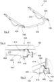
- FIG. 1 and the Fig. 2 show a transport vehicle 100 according to a first embodiment of the invention, which has a chassis 102 and two wheels 104 secured to the chassis 102 and making it possible to ensure the movement of the transport vehicle 100 on the ground.
- the chassis 102 is in the form of a U with a crossbar 106 and two longitudinal bars 108.
- the crossbar 106 here has means coupling means 110 which allow the chassis 102 to be attached to a towing vehicle such as a bicycle or a motorized system.
- the coupling means 110 can take any conceivable form depending on the towing vehicle to be attached to it. In the embodiment of the invention presented in the Figs. 1 and 2 , the coupling means 110 take the form of a joint which can be fixed to the frame of a bicycle.
- Each longitudinal bar 108 here extends towards the rear of the crossbar 106 and carries one of the wheels 104.
- the transport vehicle 100 also has a load 150 which is removably fixed to the chassis 102 between the longitudinal bars 108.
- each longitudinal bar 108 has on one side of the wheel 104, here at the rear, a first fixing system 154 and, on the other side of the wheel 104, here at the front, a second fixing system 152.
- the load 150 has, for each first fixing system 154, a first attachment means 158 and for each second fixing system 152, a second attachment means 156.
- Each fastening system 152, 154 and the associated attachment means 156, 158 are configured to provide a removable connection between them. That is to say, they can be secured to allow the attachment of the load 150 to the chassis 102 for rolling and detached to allow the separation of the load 150 and the chassis 102.
- THE Figs. 12a-c show the steps of loading the load 150 onto the chassis 102 from a position where the load 150 rests on the ground 1.
- the front part of the chassis 102 is lowered by rotation about the axis of the wheels 104, so that each first fixing system 154 comes to bear under the first attachment means 158 and lifts it.
- the rotation of the chassis 102 continues until each second fixing system 152 comes to engage with the corresponding second attachment means 156.
- the lowering is carried out in particular by the weight of the operator.
- the load 150 is attached to the chassis 102 and the transport vehicle 100 is ready to roll.
- the unloading of the load 150 is carried out in reverse, by lowering the chassis 102 to place the front of the load 150 on the ground 1 ( Fig. 12b ), by disconnecting each second fixing system 152 and the corresponding second attachment means 156, by tilting the chassis 102 towards the rear ( Fig. 12a ) to place the rear part of the load 150 and detach each first fixing system 154 from the corresponding first attachment means 158.
- the chassis 102 can then be released by moving forward (reverse arrow at 1202).
- the loading and unloading of the load 150 are therefore simple and easy due to the presence of the lever arm produced by the chassis 102.
- the load 150 comprises several packages which are not intended for the same recipient, it is always possible to unload the different packages in different unloading locations.
- Each first attachment means 158 therefore rests on the corresponding first fixing system 154.
- Each second attachment means 156 attaches to the corresponding second fixing system 152 from below.
- Each second fastening system 152 here takes the form of a lock, for example of the lock type of a car door, having a movable bolt which automatically locks onto a fixed striker when the latter enters the lock.
- the striker is here the second attachment means 156.
- the chassis 102 is equipped with an unlocking handle connected to the lock by a network of cables and which can be actuated by a user to move the bolt in order to release the striker.
- the load 150 comprises a pallet 160 and a frame 162 which is seen in detail in the Fig. 3 .
- the pallet 160 is here of the wooden pallet type with a top 164 and feet 166 spaced from each other.
- the frame 162 takes the form of an H which has a longitudinal beam 302 and two transverse beams 304.
- the longitudinal and transverse directions are taken with reference to the transport vehicle 100.
- Such an open architecture allows the frame to be inserted through one side of the pallet 160.
- each transverse beam 304 has a second attachment means 156 or a first attachment means 158 which here take the form of a blade.
- the second attachment means 156 and the first attachment means 158 are identical here but in another embodiment, they may be different.
- FIG. 4 shows a particular embodiment of a first attachment means 158.
- the first attachment means 158 comprises a base 402 mounted to rotate at the end of the transverse beam 304 about an axis of rotation 404 parallel to the longitudinal direction of the transport vehicle 100.
- the free end of the base 402 has an attachment element 406 which cooperates with the first fixing system 154.
- the upper part of the base 402 has penetration means 408 which are provided to penetrate into the pallet 160 to secure the pallet 160 and the frame 162 and thus prevent separation during rolling.
- the lower part of the base 402 has a stop 410 which limits the rotation of the base 402 upwards by coming into abutment against the transverse beam 304.
- the first attachment means 158 here comprises a screw 416 whose threaded rod passes through the stop 410 and is screwed into the transverse beam 304.
- the penetration means 408 here comprise at least one tooth 412 pointing upwards and which penetrates the pallet 160 from below and at least one lug 414 oriented inwards and which penetrates the pallet 160 from the side oriented outwards.
- FIG. 5 shows the cooperation of the first fixing system 154 and the first attachment means 158 which bears against the first fixing system 154 which takes the form of a housing for placing the attachment element 406 there.
- each attachment means 156, 158 has a return 420, here in the form of an arc. of the circle of the attachment element 406.
- the returns 420 come to bear against the external faces of the longitudinal bars 108 thus preventing them from spreading apart.
- the first fixing system 154 lifts the hooking element 406 whose teeth 412 and lugs 414 penetrate into the pallet 160.
- the stop 410 limits the amplitude of rotation of the first hooking means 158.
- the positioning of the lugs 414 on each side of the load 150 allows the latter to be centered.
- the frame 162 has, under each transverse beam 304, a spring blade 310 in an arc of a circle whose ends are fixed under the transverse beam 304 and whose rounded shape is oriented towards the ground 1. Each spring blade 310 thus raises the frame 162.
- the spring blades 310 also make it possible to press the frame 162 against the lower face of the pallet 160 and more particularly of the plate 164 in order to ensure that the penetration means 408 are in position to interact with the pallet 160.
- the spring blade 310 To ensure the action of the spring blade 310 and therefore good application against the lower face of the plate 164, the spring blade 310 must be stressed when the frame 162 is placed under the pallet 160.
- the sum of the height between the point of contact of the spring blade 310 on the ground 1 and the lower face of the transverse beam 304 and the height of the transverse beam 304 must be greater than the height of the lower face of the plate 164 on the ground 1.
- the frame 162 is then taken between the sole 168 and the lower face of the plate 164, and it is necessary that the sum of the height between the point of contact of the spring blade 310 on the upper face of the sole 168 and the lower face of the transverse beam 304 and the height of the transverse beam 304 is greater than the height from the lower face of the plate 164 to the upper face of the sole 168.
- the spring blade 310 can be replaced by any lifting means configured to place the frame 162 in abutment against the lower face of the pallet 160. and therefore more particularly of the plate 164.
- These lifting means can be, for example, straps which enclose the load 150 and the frame 162.
- These lifting means can be a parallelogram system comprising a lower part connected to the frame 162 by two parallel connecting rods, where the lower part rests on the ground or on the sole 168.
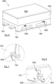
- Fig. 6 shows a second variant of the load 650 which takes the form of a pallet 651 integrating on each side of two opposite sides, a second attachment means 656 and a first attachment means 658.
- the pallet 651 can be a simple pallet or integrate a box 652 which is here closed by a cover 654.
- the pallet 651 here has spaces allowing the passage of arms of a transport device of the pallet truck type, but the pallet 651 could not have such spaces and constitute a simple bottom possibly on rollers.
- FIG. 7 shows the first attachment means 658 resting on the first fixing system 154 which also takes the form of a housing for placing the first attachment means 658 which takes the form of a horizontal beam.
- FIG. 8 shows the second attachment means 656 which is locked by the second fixing system 152 here in the form of a lock with a movable bolt 802 which locks onto the second attachment means 656 constituting the strike plate in the form of a horizontal beam.
- each of the attachment means 656 and 658 is retractable in a housing 902 provided for this purpose in the pallet 651.
- each attachment means 656, 658 is mounted to be movable in rotation in the housing 902 around a vertical axis of rotation.
- the first attachment means 658 is fully extended and in position to attach to the chassis 102.
- the first attachment means 658 is in the retraction phase or in the extension phase depending on the direction of rotation.
- FIG. 10 shows a transport vehicle 1000 according to a second embodiment of the invention which has a chassis 1002 which integrates at the front a traction system 1003, here a single-wheel pedal system and with a seat 1005 for the driver.
- the traction system 1003 can be a motorized system.
- a vertical axis of rotation is advantageously provided, either at the front wheel or at the junction between the transport vehicle 1000 and the traction system 1003.
- the chassis 1002 is in the form of a U with a transverse bar 106 and two longitudinal bars 108, each carrying a wheel 104.
- the traction system 1003 is secured to the two longitudinal bars 108, here via the transverse bar 106.
- Each longitudinal bar 108 has on one side of the wheel 104, here at the front, a second fixing system 152 and on the other side of the wheel 104, here at the rear, a first fixing system 154.
- a load 150, 650 according to the embodiments described above can be loaded between the longitudinal bars 108.
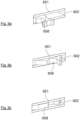
- FIG. 11 shows an enlargement of the junction between the traction system 1003 and the crossbar 106 which has a shoe 1102.
- the traction system 1003 comprises a stirrup 1104 mounted movably on the shoe 1102 in rotation around a horizontal axis of rotation 1106 and transverse to the direction of advancement of the transport vehicle 1000, and a locking device 1108.
- the locking device 1108 has at least one locked position in which the rotation of the stirrup 1104 around the shoe 1102 is blocked, and an unlocked position in which the rotation of the stirrup 1104 around the shoe 1102 is free. In the embodiment of the invention shown in the Figs. 13a-c , there are two locked positions.
- THE Figs. 13a-c show the steps of loading the load 650 onto the chassis 1002 from a position where the load 650 rests on the ground 1.
- a first locked position corresponds to a tilting position ( Fig. 13b ) and a second locked position corresponds to the rolling position ( Fig. 13c ).
- the first locked position the length of the lever arm for lowering the chassis 1002 is elongated relative to the second locked position to facilitate tilting.
- the unlocked position corresponds to the position of installation of the first fixing systems 154 with the first attachment means 658.
- the locking device 1108 is in the unlocked position and the front part of the chassis 1002 is lifted by rotation around the axis of the wheels 104, the chassis 1002 is moved back (arrow 1302) to place the load 650 between the longitudinal bars 108 and so that each first fixing system 154 is positioned under the corresponding first attachment means 658.
- the locking device 1108 is in the first locked position and the front part of the chassis 1002 is lowered by rotation about the axis of the wheels 104, so that each first fixing system 154 comes to bear under the first attachment means 658 and lifts it.
- the rotation of the chassis 1002 continues until each second fixing system 152 comes to engage with the corresponding second attachment means 656.
- the traction system 1003 is returned to the driving position and the locking device 1108 is put into the second locked position and the load 650 is hooked onto the chassis 1002 and the transport vehicle 1000 is ready to roll.
- the stirrup 1104 has a hole and the shoe 1102 has a hole for each locked position, one corresponding to the first locked position and the other corresponding to the second locked position, and the locking device 1108 here takes the form of an indexing finger 1110.
- the first locked position the hole of the stirrup 1104 aligns with the hole of the shoe 1102 corresponding to the first locked position, and the indexing finger 1110 inserts into these two aligned holes to lock the first locked position of the traction system 1003.
- the second locked position the hole of the stirrup 1104 aligns with the hole of the shoe 1102 corresponding to the second locked position, and the indexing finger 1110 inserts into these two aligned holes to lock the second locked position of the 1003 traction system.
- the crossbar 106 and the longitudinal bars 108 can be telescopic with suitable locking means for locking the telescopic parts.
- the frame 162 can have a beam longitudinal 302 and two transverse beams 304 which are telescopic and provided with suitable locking means.
- the chassis 102, 1002 may take a different shape, and be integrated into the chassis of the traction system 1003, and the two longitudinal bars 108 join in the shape of a Y or be extensions of the chassis of the traction system 1003 which is then directly secured to the two longitudinal bars 108. More generally, the chassis 102, 1002 comprises the two longitudinal bars 108.
- the lowering of the chassis 102, 1002 when loading the load 150, 650 onto the chassis 102, 1002 can also be achieved by means of assisted articulations, in particular when the longitudinal bars 108 are integral with the chassis of the traction system 1003.
- the positions of the second fastening system 152, of the first fastening system 154, of the second attachment means 156, 656, and of the first attachment means 158, 658 can be indifferently at the front or at the rear of the wheels 104, in particular depending on whether the transport vehicle 100, 1000 is towed or propelled by the towing vehicle or the traction system 1003.
- first fastening systems 154 and first attachment means 158, 658 it is possible to provide that the first attachment means 158, 658 take the form of rings, and that the first fastening systems 154 take the form of hooks inserted into the rings. It is also possible that the first attachment means 158, 658 take the form of latches, and that the first fastening systems 154 take the form of locks.
- the second fastening systems 152 which are here on either side of the median plane of the transport vehicle 10, 1000, are replaced by a single second fastening system 152 arranged on the front part of the chassis 102, 1002 and therefore of the load 150, 650.
- the transport vehicle 100, 1000 thus comprises, on each longitudinal bar 108 and on one side of the wheel 104, a first fastening system 154, and the chassis 102, 1002 has on the other side of the wheel 104, at least one second fastening system 152.
- each longitudinal bar 108 there may be two second fastening systems 152, distributed on each longitudinal bar 108, but there may be only one on the crossbar 106 or on the junction area between the two longitudinal bars 108 or on the traction system 1003.
- the frame 162 then takes the shape of a T and the pallet 651 has two first attachment means 658 on two of its opposite sides and a second attachment means 656 on one of the other two sides.
Landscapes
- Engineering & Computer Science (AREA)
- Mechanical Engineering (AREA)
- Transportation (AREA)
- Handcart (AREA)
Description
La présente invention concerne un véhicule de transport de marchandises et une charge pour un tel véhicule de transport.The present invention relates to a goods transport vehicle and a load for such a transport vehicle.
Le transport de marchandises s'effectue à l'aide de véhicules de transport. En particulier, il se développe actuellement des petits véhicules, par exemple du type triporteur ou vélo à remorque qui permettent de livrer des marchandises dans les villes. De tels véhicules de transport consistent généralement en un châssis monté sur des roues et présentant un coffre fixé sur le châssis et dans lequel des marchandises sont déposées. De tels véhicules nécessitent donc de charger les marchandises les unes après les autres dans le coffre depuis un lieu de stockage, ce qui entraîne un travail relativement long et peu ergonomique pour le personnel. La manipulation inverse s'effectue alors sur le lieu de livraison.Goods are transported using transport vehicles. In particular, small vehicles are currently being developed, such as tricycles or trailer bikes, which can be used to deliver goods in cities. Such transport vehicles generally consist of a chassis mounted on wheels and having a box fixed to the chassis and in which goods are placed. Such vehicles therefore require the goods to be loaded one after the other into the box from a storage location, which results in relatively time-consuming and ergonomic work for the personnel. The reverse handling then takes place at the delivery location.
Un objet de la présente invention est de proposer un véhicule de transport de marchandises qui ne présente pas les inconvénients de l'art antérieur et qui en particulier évite au moins un transfert manuel des marchandises les unes après les autres vers le véhicule de transport.An object of the present invention is to provide a goods transport vehicle which does not have the drawbacks of the prior art and which in particular avoids at least one manual transfer of the goods one after the other to the transport vehicle.
A cet effet, est proposé un véhicule de transport comportant les caractéristiques de la revendication 1 annexée.For this purpose, a transport vehicle is proposed having the characteristics of the attached claim 1.
Avantageusement, chaque premier moyen d'accrochage est en appui sur le premier système de fixation correspondant, et chaque deuxième moyen d'accrochage s'accroche avec le deuxième système de fixation correspondant par le dessous.Advantageously, each first attachment means rests on the corresponding first fixing system, and each second attachment means attaches to the corresponding second fixing system from below.
Avantageusement, chaque premier moyen d'accrochage comporte une base montée mobile en rotation à l'extrémité de la poutrelle transversale autour d'un axe de rotation, l'extrémité libre de la base présente un élément d'accrochage qui coopère avec le premier système de fixation, la partie supérieure de la base présente des moyens de pénétration qui sont prévus pour pénétrer dans la palette, et la partie inférieure de la base présente une butée qui limite la rotation de la base vers le haut.Advantageously, each first attachment means comprises a base mounted so as to be rotatable at the end of the transverse beam about an axis of rotation, the free end of the base has an attachment element which cooperates with the first fixing system, the upper part of the base has penetration means which are provided to penetrate the pallet, and the lower part of the base has a stop which limits the rotation of the base upwards.
Avantageusement, les moyens de pénétration comportent au moins une dent pointant vers le haut et pénétrant dans la palette par le dessous et au moins un ergot orienté vers l'intérieur et pénétrant dans la palette par le côté orienté vers l'extérieur.Advantageously, the penetration means comprise at least one tooth pointing upwards and penetrating the pallet from below and at least one lug facing inwards and penetrating the pallet from the side facing outwards.
Avantageusement, le véhicule de transport comporte des moyens de relèvement configurés pour mettre le cadre en appui contre la face inférieure de la palette.Advantageously, the transport vehicle comprises lifting means configured to place the frame in support against the lower face of the pallet.
Avantageusement, les moyens de relèvement consistent, pour chaque poutrelle transversale, en une lame ressort en arc de cercle dont les extrémités sont fixées sous la poutrelle transversale.Advantageously, the lifting means consist, for each transverse beam, of a circular arc-shaped spring blade whose ends are fixed under the transverse beam.
Avantageusement, le véhicule de transport comporte un système de traction solidaire des deux barres longitudinales.Advantageously, the transport vehicle includes a traction system attached to the two longitudinal bars.
Avantageusement, le véhicule de transport comporte une barre transversale reliant les deux barres longitudinales et comportant un sabot, le système de traction comprend un étrier monté mobile sur le sabot en rotation autour d'un axe horizontal de rotation, et un dispositif de verrouillage mobile entre au moins une position verrouillée dans laquelle la rotation de l'étrier autour du sabot est bloquée, et une position déverrouillée dans laquelle la rotation de l'étrier autour du sabot est libre.Advantageously, the transport vehicle comprises a crossbar connecting the two longitudinal bars and comprising a shoe, the traction system comprises a stirrup mounted movably on the shoe in rotation about a horizontal axis of rotation, and a locking device movable between at least one locked position in which the rotation of the stirrup around the shoe is blocked, and an unlocked position in which the rotation of the stirrup around the shoe is free.
Les caractéristiques de l'invention mentionnées ci-dessus, ainsi que d'autres, apparaîtront plus clairement à la lecture de la description suivante d'exemples de réalisation, ladite description étant faite en relation avec les dessins joints, parmi lesquels :
- la
Fig. 1 est une vue en perspective d'un véhicule de transport selon un premier mode de réalisation de l'invention, - la
Fig. 2 est une vue de dessus du véhicule de transport de laFig. 1 , - la
Fig. 3 est une vue en perspective d'un sous-ensemble d'une charge selon une première variante, - la
Fig. 4 est un détail d'un système d'accrochage dans une position libre, - la
Fig. 5 montre le système d'accrochage dans une position verrouillée, - la
Fig. 6 est une vue en perspective d'une charge selon une deuxième variante, - la
Fig. 7 et laFig. 8 sont des détails de la fixation de la charge de laFig. 6 sur le véhicule de transport de laFig. 1 , - les
Figs. 9a-c montrent des détails de la charge de laFig. 6 , - la
Fig. 10 est une vue en perspective d'un véhicule de transport selon un deuxième mode de réalisation de l'invention, - la
Fig. 11 est une vue en perspective d'une articulation du véhicule de transport de laFig. 10 , - les
Figs. 12a-c montrent les étapes de chargement du véhicule de transport de laFig. 1 , et - les
Figs. 13a-c montrent les étapes de chargement du véhicule de transport de laFig. 10 .
- there
Fig. 1 is a perspective view of a transport vehicle according to a first embodiment of the invention, - there
Fig. 2 is a top view of the transport vehicle of theFig. 1 , - there
Fig. 3 is a perspective view of a subset of a load according to a first variant, - there
Fig. 4 is a detail of a hanging system in a free position, - there
Fig. 5 shows the latching system in a locked position, - there
Fig. 6 is a perspective view of a load according to a second variant, - there
Fig. 7 and theFig. 8 are details of the load fixing of theFig. 6 on the transport vehicle of theFig. 1 , - THE
Figs. 9a-c show details of the charge of theFig. 6 , - there
Fig. 10 is a perspective view of a transport vehicle according to a second embodiment of the invention, - there
Fig. 11 is a perspective view of an articulation of the transport vehicle of theFig. 10 , - THE
Figs. 12a-c show the steps of loading the transport vehicle of theFig. 1 , And - THE
Figs. 13a-c show the steps of loading the transport vehicle of theFig. 10 .
Dans la description qui suit, les termes relatifs à une position sont pris en référence à un véhicule de transport en position de roulage, c'est-à-dire comme il est représenté sur les
La
Le châssis 102 se présente sous la forme d'un U avec une barre transversale 106 et deux barres longitudinales 108. La barre transversale 106 présente ici des moyens d'attelage 110 qui permettent d'accrocher le châssis 102 à un véhicule tracteur comme par exemple un vélo ou un système motorisé. Les moyens d'attelage 110 peuvent prendre toutes les formes envisageables en fonction du véhicule tracteur devant y être accroché. Dans le mode de réalisation de l'invention présenté sur les
Chaque barre longitudinale 108 s'étend ici vers l'arrière de la barre transversale 106 et porte une des roues 104.Each
Le véhicule de transport 100 présente également une charge 150 qui est fixée de manière amovible sur le châssis 102 entre les barres longitudinales 108. A cette fin, chaque barre longitudinale 108 présente d'un côté de la roue 104, ici à l'arrière, un premier système de fixation 154 et, de l'autre côté de la roue 104, ici à l'avant, un deuxième système de fixation 152.The
La charge 150 présente, pour chaque premier système de fixation 154, un premier moyen d'accrochage 158 et pour chaque deuxième système de fixation 152, un deuxième moyen d'accrochage 156.The
Chaque système de fixation 152, 154 et le moyen d'accrochage 156, 158 associé sont configurés pour assurer une liaison amovible entre eux. C'est-à-dire qu'ils peuvent être solidarisés pour permettre la fixation de la charge 150 sur le châssis 102 pour le roulage et désolidarisés pour permettre la séparation de la charge 150 et du châssis 102.Each
Ainsi, il est possible de charger la charge 150 sur un lieu de chargement, d'attacher la charge 150 sur le châssis 102, de transporter cette charge 150 vers un lieu de déchargement et de séparer la charge 150 du châssis 102. Le transport est ainsi facilité, puisqu'il n'est plus nécessaire de charger chaque marchandise individuellement, mais il est possible après avoir réalisé une charge 150 complète de la soulever et la transporter sans avoir recours à un engin de levage supplémentaire.Thus, it is possible to load the
Les
Sur la
Sur la
Sur la
Le déchargement de la charge 150 s'effectue de manière inverse, en abaissant le châssis 102 pour poser l'avant de la charge 150 sur le sol 1 (
Le chargement et le déchargement de la charge 150 sont donc simples et aisés du fait de la présence du bras de levier réalisé par le châssis 102. Bien sûr, si la charge 150 comporte plusieurs colis qui ne sont pas destinés au même destinataire, il est toujours possible de décharger les différents colis dans des lieux de déchargement différents.The loading and unloading of the
Chaque premier moyen d'accrochage 158 est donc en appui sur le premier système de fixation 154 correspondant. Chaque deuxième moyen d'accrochage 156 s'accroche avec le deuxième système de fixation 152 correspondant par le dessous.Each first attachment means 158 therefore rests on the corresponding
Chaque deuxième système de fixation 152 prend ici la forme d'une serrure, par exemple du type serrure d'un ouvrant de voiture, présentant un pêne mobile qui se verrouille automatiquement sur une gâche fixe lorsque celle-ci pénètre dans la serrure. La gâche est ici le deuxième moyen d'accrochage 156. Pour déverrouiller la serrure, le châssis 102 est équipé d'une poignée de déverrouillage reliée à la serrure par un réseau de câbles et pouvant être actionné par un utilisateur pour déplacer le pêne afin de libérer la gâche.Each
Selon une première variante, la charge 150 comporte une palette 160 et un cadre 162 qui est vu en détail sur la
Le cadre 162 prend la forme d'un H qui présente une poutrelle longitudinale 302 et deux poutrelles transversales 304. Les directions longitudinale et transversale sont prises en référence au véhicule de transport 100.The
Une telle architecture ouverte permet une insertion du cadre par un côté de la palette 160.Such an open architecture allows the frame to be inserted through one side of the
Les deux extrémités de chaque poutrelle transversale 304 présentent un deuxième moyen d'accrochage 156 ou un premier moyen d'accrochage 158 qui prennent ici la forme d'une lame. Les deuxièmes moyens d'accrochage 156 et les premiers moyens d'accrochage 158 sont ici identiques mais dans un autre mode de réalisation, ils peuvent être différents.The two ends of each
La
Le premier moyen d'accrochage 158 comporte une base 402 montée mobile en rotation à l'extrémité de la poutrelle transversale 304 autour d'un axe de rotation 404 parallèle à la direction longitudinale du véhicule de transport 100. L'extrémité libre de la base 402 présente un élément d'accrochage 406 qui coopère avec le premier système de fixation 154. La partie supérieure de la base 402 présente des moyens de pénétration 408 qui sont prévus pour pénétrer dans la palette 160 pour solidariser la palette 160 et le cadre 162 et ainsi éviter la désolidarisation lors du roulage. La partie inférieure de la base 402 présente une butée 410 qui limite la rotation de la base 402 vers le haut en venant en butée contre la poutrelle transversale 304. Pour limiter la rotation de la base 402 vers le bas, le premier moyen d'accrochage 158 comporte ici une vis 416 dont la tige filetée traverse la butée 410 et se visse dans la poutrelle transversale 304.The first attachment means 158 comprises a base 402 mounted to rotate at the end of the
Les moyens de pénétration 408 comprennent ici au moins une dent 412 pointant vers le haut et qui pénètre dans la palette 160 par le dessous et au moins un ergot 414 orienté vers l'intérieur et qui pénètre dans la palette 160 par le côté orienté vers l'extérieur.The penetration means 408 here comprise at least one
La
Pour éviter que les barres longitudinales 108 s'écartent sous l'effet de la charge 150, chaque moyen d'accrochage 156, 158 présente un retour 420, ici en forme d'arc de cercle de l'élément d'accrochage 406. Les retours 420 viennent en appui contre les faces extérieures des barres longitudinales 108 évitant ainsi leur écartement.To prevent the
Lorsque le châssis 102 est basculé pour soulever la partie arrière de la charge 150, le premier système de fixation 154 soulève l'élément d'accrochage 406 dont les dents 412 et les ergots 414 pénètrent dans la palette 160. La butée 410 limite l'amplitude de rotation du premier moyen d'accrochage 158. Le positionnement des ergots 414 de chaque côté de la charge 150 permet un centrage de cette dernière.When the
Afin d'assurer que le cadre 162 soit à une altitude suffisante pour que les premiers systèmes de fixation 154 puissent coopérer avec les premiers moyens d'accrochage 158, sans qu'il soit nécessaire de trop relever l'avant du châssis 102, le cadre 162 présente, sous chaque poutrelle transversale 304, une lame ressort 310 en arc de cercle dont les extrémités sont fixées sous la poutrelle transversale 304 et dont la forme arrondie est orienté vers le sol 1. Chaque lame ressort 310 relève ainsi le cadre 162.In order to ensure that the
Les lames ressort 310 permettent également de plaquer le cadre 162 contre la face inférieure de la palette 160 et plus particulièrement du plateau 164 afin d'assurer que les moyens de pénétration 408 soient en position pour interagir avec la palette 160.The
Pour assurer l'action de la lame ressort 310 et donc un bon placage contre la face inférieure du plateau 164, il faut que la lame ressort 310 soit mise en contrainte lorsque le cadre 162 est placé sous la palette 160.To ensure the action of the
Ainsi lorsque les pieds 166 reposent directement sur le sol 1, il faut que la somme de la hauteur entre le point de contact de la lame ressort 310 sur le sol 1 et la face inférieure de la poutrelle transversale 304 et de la hauteur de la poutrelle transversale 304 soit supérieure à la hauteur de la face inférieure du plateau 164 au sol 1.Thus, when the
Et lorsque la palette 160 est une palette avec une semelle 168 sous les pieds 166, le cadre 162 est alors pris entre la semelle 168 et la face inférieure du plateau 164, et il faut que la somme de la hauteur entre le point de contact de la lame ressort 310 sur la face supérieure de la semelle 168 et la face inférieure de la poutrelle transversale 304 et de la hauteur de la poutrelle transversale 304 soit supérieure à la hauteur de la face inférieure du plateau 164 à la face supérieure de la semelle 168.And when the
La lame ressort 310 peut être remplacée par tous moyens de relèvement configurés pour mettre le cadre 162 en appui contre la face inférieure de la palette 160 et donc plus particulièrement du plateau 164. Ces moyens de relèvement peuvent être par exemple des sangles qui enserrent la charge 150 et le cadre 162. Ces moyens de relèvement peuvent être un système à parallélogramme comportant une partie inférieure reliée au cadre 162 par deux biellettes parallèles, où la partie inférieure repose sur le sol ou sur la semelle 168.The
La
Les autres éléments comme par exemple la semelle 168 et les retours 420 pour empêcher l'écartement des barres longitudinales 108 peuvent être également présents.Other elements such as for example the sole 168 and the
La
La
Pour escamoter les moyens d'accrochage 656 et 658 lorsque la palette 651 n'est pas chargée sur le châssis 102, chacun des moyens d'accrochage 656 et 658 est escamotable dans un logement 902 prévu à cet effet dans la palette 651. Dans le mode de réalisation de l'invention présenté sur les
Sur la
Sur la
Sur la
La
Comme pour le châssis du véhicule de transport du premier mode de réalisation de la
Le système de traction 1003 est solidaire des deux barres longitudinales 108, ici par l'intermédiaire de la barre transversale 106.The
Chaque barre longitudinale 108 présente d'un côté de la roue 104, ici à l'avant, un deuxième système de fixation 152 et de l'autre côté de la roue 104, ici à l'arrière, un premier système de fixation 154.Each
Une charge 150, 650 selon les modes de réalisation décrits ci-dessus peut être chargée entre les barres longitudinales 108.A
La
Le système de traction 1003 comprend un étrier 1104 monté mobile sur le sabot 1102 en rotation autour d'un axe horizontal de rotation 1106 et transversal par rapport au sens d'avancement du véhicule de transport 1000, et un dispositif de verrouillage 1108.The
Le dispositif de verrouillage 1108 présente au moins une position verrouillée dans laquelle la rotation de l'étrier 1104 autour du sabot 1102 est bloquée, et une position déverrouillée dans laquelle la rotation de l'étrier 1104 autour du sabot 1102 est libre. Dans le mode de réalisation de l'invention présenté sur les
Les
Sur la
Sur la
Sur la
Dans le mode de réalisation de l'invention présenté ici, l'étrier 1104 présente un trou et le sabot 1102 présente un trou pour chaque position verrouillée, l'un correspondant à la première position verrouillée et l'autre correspondant à la deuxième position verrouillée, et le dispositif de verrouillage 1108 prend ici la forme d'un doigt d'indexage 1110. Dans la première position verrouillée, le trou de l'étrier 1104 s'aligne avec le trou du sabot 1102 correspondant à la première position verrouillée, et le doigt d'indexage 1110 s'insère dans ces deux trous alignés pour verrouiller la première position verrouillée du système de traction 1003. Dans la deuxième position verrouillée, le trou de l'étrier 1104 s'aligne avec le trou du sabot 1102 correspondant à la deuxième position verrouillée, et le doigt d'indexage 1110 s'insère dans ces deux trous alignés pour verrouiller la deuxième position verrouillée du système de traction 1003.In the embodiment of the invention presented herein, the
Pour adapter les dimensions du châssis 102, 1002 aux dimensions de la charge 150, 650, la barre transversale 106 et les barres longitudinales 108 peuvent être télescopiques avec des moyens de blocage appropriés pour bloquer les parties télescopiques. De la même manière, le cadre 162 peut présenter une poutrelle longitudinale 302 et deux poutrelles transversales 304 qui sont télescopiques et munies de moyens de blocage appropriés.To adapt the dimensions of the
D'une manière plus générale, le châssis 102, 1002 peut prendre une forme différente, et être intégré au châssis du système de traction 1003, et les deux barres longitudinales 108 se rejoignent sous la forme d'un Y ou être des extensions du châssis du système de traction 1003 qui est alors directement solidaire des deux barres longitudinales 108. D'une manière donc plus générale, le châssis 102, 1002 comporte les deux barres longitudinales 108.More generally, the
L'abaissement du châssis 102, 1002 lors du chargement de la charge 150, 650 sur le châssis 102, 1002 peut également être réalisé par l'intermédiaire d'articulations assistées, en particulier lorsque les barres longitudinales 108 sont solidaires du châssis du système de traction 1003.The lowering of the
Les positions du deuxième système de fixation 152, du premier système de fixation 154, du deuxième moyen d'accrochage 156, 656, et du premier moyen d'accrochage 158, 658 peuvent être indifféremment à l'avant ou à l'arrière des roues 104, en particulier selon que le véhicule de transport 100, 1000 soit tracté ou propulsé par le véhicule tracteur ou le système de traction 1003.The positions of the
Il est également possible d'envisager des premiers systèmes de fixation 154 et des premiers moyens d'accrochage 158, 658 différents. Par exemple, il est possible de prévoir que les premiers moyens d'accrochage 158, 658 prennent la forme d'anneaux, et que les premiers systèmes de fixation 154 prennent la forme de crochets s'insérant dans les anneaux. Il est également possible que les premiers moyens d'accrochage 158, 658 prennent la forme de gâches, et que les premiers systèmes de fixation 154 prennent la forme de serrures.It is also possible to envisage different
Il est également possible de prévoir que les deuxièmes systèmes de fixation 152 qui sont ici de part et d'autre du plan médian du véhicule de transport 10, 1000, soient remplacés par un seul deuxième système de fixation 152 disposé sur la partie avant du châssis 102, 1002 et donc de la charge 150, 650. Le véhicule de transport 100, 1000 comporte ainsi, sur chaque barre longitudinale 108 et d'un côté de la roue 104, un premier système de fixation 154, et le châssis 102, 1002 présente de l'autre côté de la roue 104, au moins un deuxième système de fixation 152.It is also possible to provide that the
Comme décrit ci-dessus, il peut y avoir deux deuxièmes systèmes de fixation 152, répartis sur chaque barre longitudinale 108, mais il peut y en avoir qu'un sur la barre transversale 106 ou sur la zone de jonction entre les deux barres longitudinales 108 ou sur le système de traction 1003.As described above, there may be two
Dans le cas de trois points de fixation, le cadre 162 prend alors la forme d'un T et la palette 651 présente deux premiers moyens d'accrochage 658 sur deux de ses côtés opposés et un deuxième moyen d'accrochage 656 sur l'un des deux autres côtés.In the case of three fixing points, the
Claims (8)
- A transport vehicle (100, 1000) including:- a chassis (102, 1002) including two longitudinal bars (108) on each of which a wheel (104) is mounted and- a load (150, 650) disposed between the longitudinal bars (108), each longitudinal bar (108) having at the rear of the wheel (104), a first fixing system (154) and,at the front of the wheel (104), at least a second fixing system (152), the load (150, 650) having, for each first fixing system (154), a first hooking means (158, 658) and for each second fixing system (152), a second hooking means (156, 656), each fixing system (152, 154) and the associated hooking means (156, 656, 158, 658) being configured to ensure a removable connection therebetween,the load (150, 650) being hooked on the chassis (102, 1002) from a position where the load (150, 650) rests on the ground (1):- by lifting the front part of the chassis (102, 1002) by rotation around the axis of the wheels (104) so that each first fixing system (154) is positioned under the first corresponding hooking means (158, 658), then- by lowering the front part of the chassis (102, 1002) by rotation around the axis of the wheels (104) so that, initially, each first fixing system (154) bears under the corresponding first hooking means (158, 658) and lifts it, then in a second step so that each second fixing system (152) is hooked with the second corresponding hooking means (156, 656), andthe load (150, 650) being unloaded from the chassis:- by lowering the front part of the chassis (102, 1002) by rotation around the axis of the wheels (104) to place the front of the load (150, 650) on the ground (1) and disconnect each second fixing system (152) and the corresponding second hooking means (156, 656), then- by lifting the front part of the chassis (102, 1002) by rotation around the axis of the wheels (104) to place the rear of the load (150, 650) on the ground (1) and disconnect each first fixing system (154) from the corresponding first hooking means (158, 658)characterised in that the load (150) includes a pallet (160) and a frame (162) placed under the pallet (160) by insertion of the frame (162) through one side of the pallet (160), the H-shaped frame (162) having a longitudinal beam (302) and two transverse beams (304), the ends of each transverse beam (304) having a second hooking means (156) or a first hooking means (158).
- The transport vehicle (100, 1000) according to claim 1, characterised in that each first attachment means (158, 658) bears on the first corresponding fixing system (154), and in that each second hooking means (156, 656) is hooked with the corresponding second fixing system (152) from below.
- The transport vehicle (100, 1000) according to claim 1 or 2, characterised in that each first attachment means (158) includes a base (402) mounted movable in rotation at the end of the transverse beam (304) around an axis of rotation (404), in that the free end of the base (402) has a hooking element (406) which cooperates with the first fixing system (154), in that the upper part of the base (402) has penetration means (408) which are intended to penetrate the pallet (160), and in that the lower part of the base (402) has a stop (410) which limits the upward rotation of the base (402).
- The transport vehicle (100, 1000) according to claim 3, characterised in that the penetration means (408) include at least one tooth (412) pointing upwards and penetrating the pallet (160) from below and at least one lug (414) oriented inwards and penetrating the pallet (160) from the side oriented outwards.
- The transport vehicle (100, 1000) according to one of claims 2 to 4, characterised in that it includes lifting means (310) configured to bear the frame (162) against the lower face of the pallet (160).
- The transport vehicle (100, 1000) according to claim 5, characterised in that the lifting means (310) consist, for each transverse beam (304), of a leaf spring (310) in an arc of a circle whose ends are fixed under the transverse beam (304).
- The transport vehicle (1000) according to one of claims 1 to 6, characterised in that it includes a traction system (1003) integral with the two longitudinal bars (108).
- The transport vehicle (1000) according to claim 7, characterised in that it includes a transverse bar (106) connecting the two longitudinal bars (108) and including a shoe (1102), in that the traction system (1003) comprises a stirrup (1104) movably mounted on the shoe (1102) in rotation around a horizontal axis of rotation (1106), and a locking device (1108) movable between at least one locked position wherein the rotation of the stirrup (1104) around the shoe (1102) is blocked, and an unlocked position wherein the rotation of the stirrup (1104) around the shoe (1102) is free.
Applications Claiming Priority (2)
| Application Number | Priority Date | Filing Date | Title |
|---|---|---|---|
| FR1561087A FR3043643B1 (en) | 2015-11-18 | 2015-11-18 | VEHICLE FOR TRANSPORTING A LOAD |
| PCT/EP2016/078009 WO2017085188A1 (en) | 2015-11-18 | 2016-11-17 | Vehicle for transporting a load |
Publications (3)
| Publication Number | Publication Date |
|---|---|
| EP3377397A1 EP3377397A1 (en) | 2018-09-26 |
| EP3377397B1 true EP3377397B1 (en) | 2024-09-18 |
| EP3377397C0 EP3377397C0 (en) | 2024-09-18 |
Family
ID=55345997
Family Applications (1)
| Application Number | Title | Priority Date | Filing Date |
|---|---|---|---|
| EP16797913.7A Active EP3377397B1 (en) | 2015-11-18 | 2016-11-17 | Vehicle for transporting a load |
Country Status (3)
| Country | Link |
|---|---|
| EP (1) | EP3377397B1 (en) |
| FR (1) | FR3043643B1 (en) |
| WO (1) | WO2017085188A1 (en) |
Families Citing this family (4)
| Publication number | Priority date | Publication date | Assignee | Title |
|---|---|---|---|---|
| DE102017005699B3 (en) * | 2017-06-19 | 2018-06-28 | RYTLE GmbH | transportation Bicycle |
| KR101923112B1 (en) * | 2017-12-04 | 2018-11-28 | 이희윤 | Expandable carrier with detachable and attachable |
| CN113895554B (en) * | 2021-11-19 | 2023-03-24 | 江西省舌尖王国供应链管理有限公司 | A commodity circulation conveyer for wisdom commodity circulation |
| GB2616482B (en) * | 2022-03-11 | 2024-04-10 | Tomcat Special Needs Innovation Ltd | A cycle for carrying cargo |
Citations (7)
| Publication number | Priority date | Publication date | Assignee | Title |
|---|---|---|---|---|
| US375911A (en) * | 1888-01-03 | Apparatus for handling brick | ||
| US2576048A (en) * | 1949-08-18 | 1951-11-20 | Allison Parsons | Truck for handling cylinders of compressed gas or the like |
| US2603501A (en) * | 1950-05-09 | 1952-07-15 | Graves James Renex | Boat trailer |
| US2638236A (en) * | 1950-11-22 | 1953-05-12 | Joseph H Prowinsky | Hand truck |
| US2870928A (en) * | 1955-12-19 | 1959-01-27 | Delphi Products Company Inc | Combination vehicle |
| US3945661A (en) * | 1973-03-15 | 1976-03-23 | Priefert Marvin J | Trailer apparatus for loading and transporting a farm unit |
| CN104512312A (en) * | 2013-09-30 | 2015-04-15 | 诺文科装备(北京)有限公司 | Functional auxiliary vehicle |
Family Cites Families (10)
| Publication number | Priority date | Publication date | Assignee | Title |
|---|---|---|---|---|
| DE617694C (en) * | 1935-08-23 | Emma Leinert Geb Biedermann | Detachable trailer for bicycles and motorcycles | |
| FR1324030A (en) * | 1962-05-28 | 1963-04-12 | Haemmerlin Georges | Small multipurpose cart |
| DE3214448A1 (en) * | 1982-04-20 | 1983-10-20 | Eberhard 6100 Darmstadt Malwitz | Two-wheeled trailer for bicycles and mopeds |
| US4725067A (en) * | 1985-10-03 | 1988-02-16 | Thomas Lundy | Bicycle trailer |
| GB9414026D0 (en) * | 1994-07-12 | 1994-08-31 | Designer Tek Ltd | Demountable palletized box trailer |
| US20020096857A1 (en) * | 2001-01-19 | 2002-07-25 | Martin Valdez | Bicycle trailer for a baby stroller frame with a seat |
| FR2838398B1 (en) * | 2002-04-11 | 2004-12-24 | Fideves | TRAILER FOR CONVEYOR TRAIN |
| DE102011017346B4 (en) * | 2011-04-16 | 2022-01-05 | Jungheinrich Aktiengesellschaft | Trailer for a pallet truck in a tugger train |
| CH708860A2 (en) * | 2013-11-15 | 2015-05-15 | Josef Von Ah | Exchange device for an alternating tools umbaubares vehicle / cargo bike. |
| FR3019795B1 (en) * | 2014-04-09 | 2017-07-21 | 2M | TRAILER, PREFERABLY ATTEMPT TO A LIGHT VEHICLE SUCH AS A BIKE, A QUADRICYCLE OR A CYCLOMOTOR |
-
2015
- 2015-11-18 FR FR1561087A patent/FR3043643B1/en active Active
-
2016
- 2016-11-17 WO PCT/EP2016/078009 patent/WO2017085188A1/en not_active Ceased
- 2016-11-17 EP EP16797913.7A patent/EP3377397B1/en active Active
Patent Citations (7)
| Publication number | Priority date | Publication date | Assignee | Title |
|---|---|---|---|---|
| US375911A (en) * | 1888-01-03 | Apparatus for handling brick | ||
| US2576048A (en) * | 1949-08-18 | 1951-11-20 | Allison Parsons | Truck for handling cylinders of compressed gas or the like |
| US2603501A (en) * | 1950-05-09 | 1952-07-15 | Graves James Renex | Boat trailer |
| US2638236A (en) * | 1950-11-22 | 1953-05-12 | Joseph H Prowinsky | Hand truck |
| US2870928A (en) * | 1955-12-19 | 1959-01-27 | Delphi Products Company Inc | Combination vehicle |
| US3945661A (en) * | 1973-03-15 | 1976-03-23 | Priefert Marvin J | Trailer apparatus for loading and transporting a farm unit |
| CN104512312A (en) * | 2013-09-30 | 2015-04-15 | 诺文科装备(北京)有限公司 | Functional auxiliary vehicle |
Also Published As
| Publication number | Publication date |
|---|---|
| EP3377397A1 (en) | 2018-09-26 |
| FR3043643B1 (en) | 2019-04-26 |
| FR3043643A1 (en) | 2017-05-19 |
| EP3377397C0 (en) | 2024-09-18 |
| WO2017085188A1 (en) | 2017-05-26 |
Similar Documents
| Publication | Publication Date | Title |
|---|---|---|
| EP0960844B1 (en) | Autonomous and automatic chock for immobilizing vehicles and modular immobilizing device using the chocks | |
| EP3377397B1 (en) | Vehicle for transporting a load | |
| FR2532255A1 (en) | ARTICULATED TRAILER, PARTICULARLY FOR LOADING MOTORCYCLES | |
| FR2577862A1 (en) | CARRIER VEHICLE FOR LIFT, TRANSPORT AND DEVERSER, FOR EXAMPLE A CRASS POCKET | |
| CA2950352A1 (en) | Gripper for gripping, moving and depositing a pallet | |
| EP3247610A1 (en) | Cart for transporting or storing a bicycle | |
| EP1045789B1 (en) | Device for storing and transporting a motorcycle | |
| EP3585631B1 (en) | Wheeled logistical module provided with a towing device | |
| EP2860134B1 (en) | Container for storing and transporting goods | |
| EP2253562B1 (en) | Device for transporting prefabricated flat objects. | |
| WO1998054069A1 (en) | Device for storing and transporting a motorcycle | |
| EP3400622B1 (en) | Stationary shelter for storing at least one electrical energy storage unit | |
| FR3014092A1 (en) | FAST ATTACHING DEVICE FOR HANDLING OR LOADING MACHINES | |
| EP0447338B1 (en) | Load-carrying device adaptable on a vehicle ball-hitch | |
| FR2561601A1 (en) | Trolley of the ''barrow'' type for transporting objects such as suitcases | |
| FR2750088A1 (en) | Vehicle equipped with hydraulic lifting arm | |
| EP0883515B1 (en) | Device for releasably fastening cylindrical objects on a vehicle | |
| FR3020351A1 (en) | DEVICE FOR LOADING WASTE BINS FROM A PLATFORM | |
| FR3043394B1 (en) | SYSTEM FOR PACKING A FORKLIFT UNDER A PLATFORM FOR LOADING A TRANSPORT VEHICLE | |
| FR2926758A1 (en) | Loading arrangement for e.g. trailer in military application, has sliding unit distinct from maintaining unit that maintains base and subframe to be inseparable during their sliding, where maintaining unit is distinct from locking unit | |
| EP4650224A1 (en) | Four-wheel support device for agricultural tractor | |
| EP3156268B1 (en) | Trailer comprising a draw bar provided with means for quick installation onto a chassis of the trailer | |
| FR3037308A1 (en) | TRAILER FOR REACHING A TRACTOR VEHICLE AND ASSEMBLY COMPRISING SUCH A TRAILER | |
| FR2749552A1 (en) | Intermediate removable handling and stowing plate for containers | |
| LU84125A1 (en) | TRAILER |
Legal Events
| Date | Code | Title | Description |
|---|---|---|---|
| STAA | Information on the status of an ep patent application or granted ep patent |
Free format text: STATUS: UNKNOWN |
|
| STAA | Information on the status of an ep patent application or granted ep patent |
Free format text: STATUS: THE INTERNATIONAL PUBLICATION HAS BEEN MADE |
|
| PUAI | Public reference made under article 153(3) epc to a published international application that has entered the european phase |
Free format text: ORIGINAL CODE: 0009012 |
|
| STAA | Information on the status of an ep patent application or granted ep patent |
Free format text: STATUS: REQUEST FOR EXAMINATION WAS MADE |
|
| 17P | Request for examination filed |
Effective date: 20180615 |
|
| AK | Designated contracting states |
Kind code of ref document: A1 Designated state(s): AL AT BE BG CH CY CZ DE DK EE ES FI FR GB GR HR HU IE IS IT LI LT LU LV MC MK MT NL NO PL PT RO RS SE SI SK SM TR |
|
| AX | Request for extension of the european patent |
Extension state: BA ME |
|
| RIN1 | Information on inventor provided before grant (corrected) |
Inventor name: LEVILLAIN, CHARLES |
|
| DAV | Request for validation of the european patent (deleted) | ||
| DAX | Request for extension of the european patent (deleted) | ||
| STAA | Information on the status of an ep patent application or granted ep patent |
Free format text: STATUS: EXAMINATION IS IN PROGRESS |
|
| 17Q | First examination report despatched |
Effective date: 20201001 |
|
| RAP3 | Party data changed (applicant data changed or rights of an application transferred) |
Owner name: FLEXIMODAL |
|
| GRAP | Despatch of communication of intention to grant a patent |
Free format text: ORIGINAL CODE: EPIDOSNIGR1 |
|
| STAA | Information on the status of an ep patent application or granted ep patent |
Free format text: STATUS: GRANT OF PATENT IS INTENDED |
|
| INTG | Intention to grant announced |
Effective date: 20240409 |
|
| GRAS | Grant fee paid |
Free format text: ORIGINAL CODE: EPIDOSNIGR3 |
|
| GRAA | (expected) grant |
Free format text: ORIGINAL CODE: 0009210 |
|
| STAA | Information on the status of an ep patent application or granted ep patent |
Free format text: STATUS: THE PATENT HAS BEEN GRANTED |
|
| AK | Designated contracting states |
Kind code of ref document: B1 Designated state(s): AL AT BE BG CH CY CZ DE DK EE ES FI FR GB GR HR HU IE IS IT LI LT LU LV MC MK MT NL NO PL PT RO RS SE SI SK SM TR |
|
| REG | Reference to a national code |
Ref country code: GB Ref legal event code: FG4D Free format text: NOT ENGLISH |
|
| REG | Reference to a national code |
Ref country code: CH Ref legal event code: EP |
|
| REG | Reference to a national code |
Ref country code: DE Ref legal event code: R096 Ref document number: 602016089466 Country of ref document: DE |
|
| REG | Reference to a national code |
Ref country code: IE Ref legal event code: FG4D Free format text: LANGUAGE OF EP DOCUMENT: FRENCH |
|
| U01 | Request for unitary effect filed |
Effective date: 20241011 |
|
| U07 | Unitary effect registered |
Designated state(s): AT BE BG DE DK EE FI FR IT LT LU LV MT NL PT RO SE SI Effective date: 20241030 |
|
| U20 | Renewal fee for the european patent with unitary effect paid |
Year of fee payment: 9 Effective date: 20241126 |
|
| PG25 | Lapsed in a contracting state [announced via postgrant information from national office to epo] |
Ref country code: NO Free format text: LAPSE BECAUSE OF FAILURE TO SUBMIT A TRANSLATION OF THE DESCRIPTION OR TO PAY THE FEE WITHIN THE PRESCRIBED TIME-LIMIT Effective date: 20241218 |
|
| PG25 | Lapsed in a contracting state [announced via postgrant information from national office to epo] |
Ref country code: GR Free format text: LAPSE BECAUSE OF FAILURE TO SUBMIT A TRANSLATION OF THE DESCRIPTION OR TO PAY THE FEE WITHIN THE PRESCRIBED TIME-LIMIT Effective date: 20241219 |
|
| PGFP | Annual fee paid to national office [announced via postgrant information from national office to epo] |
Ref country code: GB Payment date: 20241219 Year of fee payment: 9 |
|
| PG25 | Lapsed in a contracting state [announced via postgrant information from national office to epo] |
Ref country code: HR Free format text: LAPSE BECAUSE OF FAILURE TO SUBMIT A TRANSLATION OF THE DESCRIPTION OR TO PAY THE FEE WITHIN THE PRESCRIBED TIME-LIMIT Effective date: 20240918 |
|
| PG25 | Lapsed in a contracting state [announced via postgrant information from national office to epo] |
Ref country code: RS Free format text: LAPSE BECAUSE OF FAILURE TO SUBMIT A TRANSLATION OF THE DESCRIPTION OR TO PAY THE FEE WITHIN THE PRESCRIBED TIME-LIMIT Effective date: 20241218 |
|
| PG25 | Lapsed in a contracting state [announced via postgrant information from national office to epo] |
Ref country code: RS Free format text: LAPSE BECAUSE OF FAILURE TO SUBMIT A TRANSLATION OF THE DESCRIPTION OR TO PAY THE FEE WITHIN THE PRESCRIBED TIME-LIMIT Effective date: 20241218 Ref country code: NO Free format text: LAPSE BECAUSE OF FAILURE TO SUBMIT A TRANSLATION OF THE DESCRIPTION OR TO PAY THE FEE WITHIN THE PRESCRIBED TIME-LIMIT Effective date: 20241218 Ref country code: HR Free format text: LAPSE BECAUSE OF FAILURE TO SUBMIT A TRANSLATION OF THE DESCRIPTION OR TO PAY THE FEE WITHIN THE PRESCRIBED TIME-LIMIT Effective date: 20240918 Ref country code: GR Free format text: LAPSE BECAUSE OF FAILURE TO SUBMIT A TRANSLATION OF THE DESCRIPTION OR TO PAY THE FEE WITHIN THE PRESCRIBED TIME-LIMIT Effective date: 20241219 |
|
| PG25 | Lapsed in a contracting state [announced via postgrant information from national office to epo] |
Ref country code: IS Free format text: LAPSE BECAUSE OF FAILURE TO SUBMIT A TRANSLATION OF THE DESCRIPTION OR TO PAY THE FEE WITHIN THE PRESCRIBED TIME-LIMIT Effective date: 20250118 |
|
| PG25 | Lapsed in a contracting state [announced via postgrant information from national office to epo] |
Ref country code: SM Free format text: LAPSE BECAUSE OF FAILURE TO SUBMIT A TRANSLATION OF THE DESCRIPTION OR TO PAY THE FEE WITHIN THE PRESCRIBED TIME-LIMIT Effective date: 20240918 |
|
| PG25 | Lapsed in a contracting state [announced via postgrant information from national office to epo] |
Ref country code: ES Free format text: LAPSE BECAUSE OF FAILURE TO SUBMIT A TRANSLATION OF THE DESCRIPTION OR TO PAY THE FEE WITHIN THE PRESCRIBED TIME-LIMIT Effective date: 20240918 |
|
| PG25 | Lapsed in a contracting state [announced via postgrant information from national office to epo] |
Ref country code: CZ Free format text: LAPSE BECAUSE OF FAILURE TO SUBMIT A TRANSLATION OF THE DESCRIPTION OR TO PAY THE FEE WITHIN THE PRESCRIBED TIME-LIMIT Effective date: 20240918 Ref country code: PL Free format text: LAPSE BECAUSE OF FAILURE TO SUBMIT A TRANSLATION OF THE DESCRIPTION OR TO PAY THE FEE WITHIN THE PRESCRIBED TIME-LIMIT Effective date: 20240918 |
|
| PG25 | Lapsed in a contracting state [announced via postgrant information from national office to epo] |
Ref country code: SK Free format text: LAPSE BECAUSE OF FAILURE TO SUBMIT A TRANSLATION OF THE DESCRIPTION OR TO PAY THE FEE WITHIN THE PRESCRIBED TIME-LIMIT Effective date: 20240918 |
|
| REG | Reference to a national code |
Ref country code: CH Ref legal event code: PL |
|
| PG25 | Lapsed in a contracting state [announced via postgrant information from national office to epo] |
Ref country code: MC Free format text: LAPSE BECAUSE OF FAILURE TO SUBMIT A TRANSLATION OF THE DESCRIPTION OR TO PAY THE FEE WITHIN THE PRESCRIBED TIME-LIMIT Effective date: 20240918 |
|
| REG | Reference to a national code |
Ref country code: CH Ref legal event code: PL |
|
| PG25 | Lapsed in a contracting state [announced via postgrant information from national office to epo] |
Ref country code: CH Free format text: LAPSE BECAUSE OF NON-PAYMENT OF DUE FEES Effective date: 20241130 |
|
| PLBE | No opposition filed within time limit |
Free format text: ORIGINAL CODE: 0009261 |
|
| STAA | Information on the status of an ep patent application or granted ep patent |
Free format text: STATUS: NO OPPOSITION FILED WITHIN TIME LIMIT |
|
| 26N | No opposition filed |
Effective date: 20250619 |
|
| PG25 | Lapsed in a contracting state [announced via postgrant information from national office to epo] |
Ref country code: IE Free format text: LAPSE BECAUSE OF NON-PAYMENT OF DUE FEES Effective date: 20241117 |
|
| U20 | Renewal fee for the european patent with unitary effect paid |
Year of fee payment: 10 Effective date: 20251125 |
|
| PG25 | Lapsed in a contracting state [announced via postgrant information from national office to epo] |
Ref country code: HU Free format text: LAPSE BECAUSE OF FAILURE TO SUBMIT A TRANSLATION OF THE DESCRIPTION OR TO PAY THE FEE WITHIN THE PRESCRIBED TIME-LIMIT; INVALID AB INITIO Effective date: 20161117 |