EP3377317B1 - Stucture d'un panneau stratifié pour des systèmes d'éclairage imitant le ciel ensoleillé - Google Patents
Stucture d'un panneau stratifié pour des systèmes d'éclairage imitant le ciel ensoleillé Download PDFInfo
- Publication number
- EP3377317B1 EP3377317B1 EP16810258.0A EP16810258A EP3377317B1 EP 3377317 B1 EP3377317 B1 EP 3377317B1 EP 16810258 A EP16810258 A EP 16810258A EP 3377317 B1 EP3377317 B1 EP 3377317B1
- Authority
- EP
- European Patent Office
- Prior art keywords
- meters
- light
- coating
- rayleigh
- polymeric layer
- Prior art date
- Legal status (The legal status is an assumption and is not a legal conclusion. Google has not performed a legal analysis and makes no representation as to the accuracy of the status listed.)
- Active
Links
Images


Classifications
-
- B—PERFORMING OPERATIONS; TRANSPORTING
- B32—LAYERED PRODUCTS
- B32B—LAYERED PRODUCTS, i.e. PRODUCTS BUILT-UP OF STRATA OF FLAT OR NON-FLAT, e.g. CELLULAR OR HONEYCOMB, FORM
- B32B17/00—Layered products essentially comprising sheet glass, or glass, slag, or like fibres
- B32B17/06—Layered products essentially comprising sheet glass, or glass, slag, or like fibres comprising glass as the main or only constituent of a layer, next to another layer of a specific material
- B32B17/10—Layered products essentially comprising sheet glass, or glass, slag, or like fibres comprising glass as the main or only constituent of a layer, next to another layer of a specific material of synthetic resin
- B32B17/10005—Layered products essentially comprising sheet glass, or glass, slag, or like fibres comprising glass as the main or only constituent of a layer, next to another layer of a specific material of synthetic resin laminated safety glass or glazing
- B32B17/1055—Layered products essentially comprising sheet glass, or glass, slag, or like fibres comprising glass as the main or only constituent of a layer, next to another layer of a specific material of synthetic resin laminated safety glass or glazing characterized by the resin layer, i.e. interlayer
- B32B17/10614—Layered products essentially comprising sheet glass, or glass, slag, or like fibres comprising glass as the main or only constituent of a layer, next to another layer of a specific material of synthetic resin laminated safety glass or glazing characterized by the resin layer, i.e. interlayer comprising particles for purposes other than dyeing
-
- B—PERFORMING OPERATIONS; TRANSPORTING
- B32—LAYERED PRODUCTS
- B32B—LAYERED PRODUCTS, i.e. PRODUCTS BUILT-UP OF STRATA OF FLAT OR NON-FLAT, e.g. CELLULAR OR HONEYCOMB, FORM
- B32B17/00—Layered products essentially comprising sheet glass, or glass, slag, or like fibres
- B32B17/06—Layered products essentially comprising sheet glass, or glass, slag, or like fibres comprising glass as the main or only constituent of a layer, next to another layer of a specific material
- B32B17/10—Layered products essentially comprising sheet glass, or glass, slag, or like fibres comprising glass as the main or only constituent of a layer, next to another layer of a specific material of synthetic resin
- B32B17/10005—Layered products essentially comprising sheet glass, or glass, slag, or like fibres comprising glass as the main or only constituent of a layer, next to another layer of a specific material of synthetic resin laminated safety glass or glazing
- B32B17/10165—Functional features of the laminated safety glass or glazing
- B32B17/10431—Specific parts for the modulation of light incorporated into the laminated safety glass or glazing
- B32B17/1044—Invariable transmission
- B32B17/10458—Polarization selective transmission
-
- B—PERFORMING OPERATIONS; TRANSPORTING
- B32—LAYERED PRODUCTS
- B32B—LAYERED PRODUCTS, i.e. PRODUCTS BUILT-UP OF STRATA OF FLAT OR NON-FLAT, e.g. CELLULAR OR HONEYCOMB, FORM
- B32B17/00—Layered products essentially comprising sheet glass, or glass, slag, or like fibres
- B32B17/06—Layered products essentially comprising sheet glass, or glass, slag, or like fibres comprising glass as the main or only constituent of a layer, next to another layer of a specific material
- B32B17/10—Layered products essentially comprising sheet glass, or glass, slag, or like fibres comprising glass as the main or only constituent of a layer, next to another layer of a specific material of synthetic resin
- B32B17/10005—Layered products essentially comprising sheet glass, or glass, slag, or like fibres comprising glass as the main or only constituent of a layer, next to another layer of a specific material of synthetic resin laminated safety glass or glazing
- B32B17/10009—Layered products essentially comprising sheet glass, or glass, slag, or like fibres comprising glass as the main or only constituent of a layer, next to another layer of a specific material of synthetic resin laminated safety glass or glazing characterized by the number, the constitution or treatment of glass sheets
- B32B17/10036—Layered products essentially comprising sheet glass, or glass, slag, or like fibres comprising glass as the main or only constituent of a layer, next to another layer of a specific material of synthetic resin laminated safety glass or glazing characterized by the number, the constitution or treatment of glass sheets comprising two outer glass sheets
-
- B—PERFORMING OPERATIONS; TRANSPORTING
- B32—LAYERED PRODUCTS
- B32B—LAYERED PRODUCTS, i.e. PRODUCTS BUILT-UP OF STRATA OF FLAT OR NON-FLAT, e.g. CELLULAR OR HONEYCOMB, FORM
- B32B17/00—Layered products essentially comprising sheet glass, or glass, slag, or like fibres
- B32B17/06—Layered products essentially comprising sheet glass, or glass, slag, or like fibres comprising glass as the main or only constituent of a layer, next to another layer of a specific material
- B32B17/10—Layered products essentially comprising sheet glass, or glass, slag, or like fibres comprising glass as the main or only constituent of a layer, next to another layer of a specific material of synthetic resin
- B32B17/10005—Layered products essentially comprising sheet glass, or glass, slag, or like fibres comprising glass as the main or only constituent of a layer, next to another layer of a specific material of synthetic resin laminated safety glass or glazing
- B32B17/1055—Layered products essentially comprising sheet glass, or glass, slag, or like fibres comprising glass as the main or only constituent of a layer, next to another layer of a specific material of synthetic resin laminated safety glass or glazing characterized by the resin layer, i.e. interlayer
- B32B17/10761—Layered products essentially comprising sheet glass, or glass, slag, or like fibres comprising glass as the main or only constituent of a layer, next to another layer of a specific material of synthetic resin laminated safety glass or glazing characterized by the resin layer, i.e. interlayer containing vinyl acetal
-
- B—PERFORMING OPERATIONS; TRANSPORTING
- B32—LAYERED PRODUCTS
- B32B—LAYERED PRODUCTS, i.e. PRODUCTS BUILT-UP OF STRATA OF FLAT OR NON-FLAT, e.g. CELLULAR OR HONEYCOMB, FORM
- B32B17/00—Layered products essentially comprising sheet glass, or glass, slag, or like fibres
- B32B17/06—Layered products essentially comprising sheet glass, or glass, slag, or like fibres comprising glass as the main or only constituent of a layer, next to another layer of a specific material
- B32B17/10—Layered products essentially comprising sheet glass, or glass, slag, or like fibres comprising glass as the main or only constituent of a layer, next to another layer of a specific material of synthetic resin
- B32B17/10005—Layered products essentially comprising sheet glass, or glass, slag, or like fibres comprising glass as the main or only constituent of a layer, next to another layer of a specific material of synthetic resin laminated safety glass or glazing
- B32B17/1055—Layered products essentially comprising sheet glass, or glass, slag, or like fibres comprising glass as the main or only constituent of a layer, next to another layer of a specific material of synthetic resin laminated safety glass or glazing characterized by the resin layer, i.e. interlayer
- B32B17/10788—Layered products essentially comprising sheet glass, or glass, slag, or like fibres comprising glass as the main or only constituent of a layer, next to another layer of a specific material of synthetic resin laminated safety glass or glazing characterized by the resin layer, i.e. interlayer containing ethylene vinylacetate
-
- B—PERFORMING OPERATIONS; TRANSPORTING
- B32—LAYERED PRODUCTS
- B32B—LAYERED PRODUCTS, i.e. PRODUCTS BUILT-UP OF STRATA OF FLAT OR NON-FLAT, e.g. CELLULAR OR HONEYCOMB, FORM
- B32B7/00—Layered products characterised by the relation between layers; Layered products characterised by the relative orientation of features between layers, or by the relative values of a measurable parameter between layers, i.e. products comprising layers having different physical, chemical or physicochemical properties; Layered products characterised by the interconnection of layers
- B32B7/04—Interconnection of layers
- B32B7/12—Interconnection of layers using interposed adhesives or interposed materials with bonding properties
-
- C—CHEMISTRY; METALLURGY
- C03—GLASS; MINERAL OR SLAG WOOL
- C03C—CHEMICAL COMPOSITION OF GLASSES, GLAZES OR VITREOUS ENAMELS; SURFACE TREATMENT OF GLASS; SURFACE TREATMENT OF FIBRES OR FILAMENTS MADE FROM GLASS, MINERALS OR SLAGS; JOINING GLASS TO GLASS OR OTHER MATERIALS
- C03C17/00—Surface treatment of glass, not in the form of fibres or filaments, by coating
- C03C17/006—Surface treatment of glass, not in the form of fibres or filaments, by coating with materials of composite character
- C03C17/007—Surface treatment of glass, not in the form of fibres or filaments, by coating with materials of composite character containing a dispersed phase, e.g. particles, fibres or flakes, in a continuous phase
-
- C—CHEMISTRY; METALLURGY
- C03—GLASS; MINERAL OR SLAG WOOL
- C03C—CHEMICAL COMPOSITION OF GLASSES, GLAZES OR VITREOUS ENAMELS; SURFACE TREATMENT OF GLASS; SURFACE TREATMENT OF FIBRES OR FILAMENTS MADE FROM GLASS, MINERALS OR SLAGS; JOINING GLASS TO GLASS OR OTHER MATERIALS
- C03C27/00—Joining pieces of glass to pieces of other inorganic material; Joining glass to glass other than by fusing
- C03C27/06—Joining glass to glass by processes other than fusing
- C03C27/10—Joining glass to glass by processes other than fusing with the aid of adhesive specially adapted for that purpose
-
- F—MECHANICAL ENGINEERING; LIGHTING; HEATING; WEAPONS; BLASTING
- F21—LIGHTING
- F21V—FUNCTIONAL FEATURES OR DETAILS OF LIGHTING DEVICES OR SYSTEMS THEREOF; STRUCTURAL COMBINATIONS OF LIGHTING DEVICES WITH OTHER ARTICLES, NOT OTHERWISE PROVIDED FOR
- F21V3/00—Globes; Bowls; Cover glasses
- F21V3/04—Globes; Bowls; Cover glasses characterised by materials, surface treatments or coatings
- F21V3/10—Globes; Bowls; Cover glasses characterised by materials, surface treatments or coatings characterised by coatings
-
- F—MECHANICAL ENGINEERING; LIGHTING; HEATING; WEAPONS; BLASTING
- F21—LIGHTING
- F21V—FUNCTIONAL FEATURES OR DETAILS OF LIGHTING DEVICES OR SYSTEMS THEREOF; STRUCTURAL COMBINATIONS OF LIGHTING DEVICES WITH OTHER ARTICLES, NOT OTHERWISE PROVIDED FOR
- F21V9/00—Elements for modifying spectral properties, polarisation or intensity of the light emitted, e.g. filters
- F21V9/02—Elements for modifying spectral properties, polarisation or intensity of the light emitted, e.g. filters for simulating daylight
-
- G—PHYSICS
- G02—OPTICS
- G02B—OPTICAL ELEMENTS, SYSTEMS OR APPARATUS
- G02B5/00—Optical elements other than lenses
- G02B5/02—Diffusing elements; Afocal elements
- G02B5/0205—Diffusing elements; Afocal elements characterised by the diffusing properties
- G02B5/0236—Diffusing elements; Afocal elements characterised by the diffusing properties the diffusion taking place within the volume of the element
- G02B5/0242—Diffusing elements; Afocal elements characterised by the diffusing properties the diffusion taking place within the volume of the element by means of dispersed particles
-
- B—PERFORMING OPERATIONS; TRANSPORTING
- B32—LAYERED PRODUCTS
- B32B—LAYERED PRODUCTS, i.e. PRODUCTS BUILT-UP OF STRATA OF FLAT OR NON-FLAT, e.g. CELLULAR OR HONEYCOMB, FORM
- B32B2250/00—Layers arrangement
- B32B2250/03—3 layers
-
- B—PERFORMING OPERATIONS; TRANSPORTING
- B32—LAYERED PRODUCTS
- B32B—LAYERED PRODUCTS, i.e. PRODUCTS BUILT-UP OF STRATA OF FLAT OR NON-FLAT, e.g. CELLULAR OR HONEYCOMB, FORM
- B32B2250/00—Layers arrangement
- B32B2250/40—Symmetrical or sandwich layers, e.g. ABA, ABCBA, ABCCBA
-
- B—PERFORMING OPERATIONS; TRANSPORTING
- B32—LAYERED PRODUCTS
- B32B—LAYERED PRODUCTS, i.e. PRODUCTS BUILT-UP OF STRATA OF FLAT OR NON-FLAT, e.g. CELLULAR OR HONEYCOMB, FORM
- B32B2255/00—Coating on the layer surface
- B32B2255/10—Coating on the layer surface on synthetic resin layer or on natural or synthetic rubber layer
-
- B—PERFORMING OPERATIONS; TRANSPORTING
- B32—LAYERED PRODUCTS
- B32B—LAYERED PRODUCTS, i.e. PRODUCTS BUILT-UP OF STRATA OF FLAT OR NON-FLAT, e.g. CELLULAR OR HONEYCOMB, FORM
- B32B2255/00—Coating on the layer surface
- B32B2255/26—Polymeric coating
-
- B—PERFORMING OPERATIONS; TRANSPORTING
- B32—LAYERED PRODUCTS
- B32B—LAYERED PRODUCTS, i.e. PRODUCTS BUILT-UP OF STRATA OF FLAT OR NON-FLAT, e.g. CELLULAR OR HONEYCOMB, FORM
- B32B2255/00—Coating on the layer surface
- B32B2255/28—Multiple coating on one surface
-
- B—PERFORMING OPERATIONS; TRANSPORTING
- B32—LAYERED PRODUCTS
- B32B—LAYERED PRODUCTS, i.e. PRODUCTS BUILT-UP OF STRATA OF FLAT OR NON-FLAT, e.g. CELLULAR OR HONEYCOMB, FORM
- B32B2307/00—Properties of the layers or laminate
- B32B2307/40—Properties of the layers or laminate having particular optical properties
- B32B2307/406—Bright, glossy, shiny surface
-
- B—PERFORMING OPERATIONS; TRANSPORTING
- B32—LAYERED PRODUCTS
- B32B—LAYERED PRODUCTS, i.e. PRODUCTS BUILT-UP OF STRATA OF FLAT OR NON-FLAT, e.g. CELLULAR OR HONEYCOMB, FORM
- B32B2307/00—Properties of the layers or laminate
- B32B2307/40—Properties of the layers or laminate having particular optical properties
- B32B2307/412—Transparent
-
- B—PERFORMING OPERATIONS; TRANSPORTING
- B32—LAYERED PRODUCTS
- B32B—LAYERED PRODUCTS, i.e. PRODUCTS BUILT-UP OF STRATA OF FLAT OR NON-FLAT, e.g. CELLULAR OR HONEYCOMB, FORM
- B32B2307/00—Properties of the layers or laminate
- B32B2307/40—Properties of the layers or laminate having particular optical properties
- B32B2307/414—Translucent
-
- B—PERFORMING OPERATIONS; TRANSPORTING
- B32—LAYERED PRODUCTS
- B32B—LAYERED PRODUCTS, i.e. PRODUCTS BUILT-UP OF STRATA OF FLAT OR NON-FLAT, e.g. CELLULAR OR HONEYCOMB, FORM
- B32B2307/00—Properties of the layers or laminate
- B32B2307/40—Properties of the layers or laminate having particular optical properties
- B32B2307/42—Polarizing, birefringent, filtering
-
- C—CHEMISTRY; METALLURGY
- C03—GLASS; MINERAL OR SLAG WOOL
- C03C—CHEMICAL COMPOSITION OF GLASSES, GLAZES OR VITREOUS ENAMELS; SURFACE TREATMENT OF GLASS; SURFACE TREATMENT OF FIBRES OR FILAMENTS MADE FROM GLASS, MINERALS OR SLAGS; JOINING GLASS TO GLASS OR OTHER MATERIALS
- C03C2217/00—Coatings on glass
- C03C2217/40—Coatings comprising at least one inhomogeneous layer
- C03C2217/43—Coatings comprising at least one inhomogeneous layer consisting of a dispersed phase in a continuous phase
- C03C2217/44—Coatings comprising at least one inhomogeneous layer consisting of a dispersed phase in a continuous phase characterized by the composition of the continuous phase
- C03C2217/445—Organic continuous phases
-
- C—CHEMISTRY; METALLURGY
- C03—GLASS; MINERAL OR SLAG WOOL
- C03C—CHEMICAL COMPOSITION OF GLASSES, GLAZES OR VITREOUS ENAMELS; SURFACE TREATMENT OF GLASS; SURFACE TREATMENT OF FIBRES OR FILAMENTS MADE FROM GLASS, MINERALS OR SLAGS; JOINING GLASS TO GLASS OR OTHER MATERIALS
- C03C2217/00—Coatings on glass
- C03C2217/40—Coatings comprising at least one inhomogeneous layer
- C03C2217/43—Coatings comprising at least one inhomogeneous layer consisting of a dispersed phase in a continuous phase
- C03C2217/46—Coatings comprising at least one inhomogeneous layer consisting of a dispersed phase in a continuous phase characterized by the dispersed phase
- C03C2217/47—Coatings comprising at least one inhomogeneous layer consisting of a dispersed phase in a continuous phase characterized by the dispersed phase consisting of a specific material
- C03C2217/475—Inorganic materials
-
- F—MECHANICAL ENGINEERING; LIGHTING; HEATING; WEAPONS; BLASTING
- F21—LIGHTING
- F21V—FUNCTIONAL FEATURES OR DETAILS OF LIGHTING DEVICES OR SYSTEMS THEREOF; STRUCTURAL COMBINATIONS OF LIGHTING DEVICES WITH OTHER ARTICLES, NOT OTHERWISE PROVIDED FOR
- F21V7/00—Reflectors for light sources
Definitions
- the present disclosure relates generally to lighting systems, in particular to lighting systems for optically providing a widened perception/impression of the ambient space and in particular for imitating natural sunlight illumination. Moreover, the present disclosure relates generally to panel structures such as glass structures with chromatic features.
- EP 2 304 478 A1 discloses lighting systems that use a light source producing visible light, and a panel containing nanoparticles used in transmission, i.e. the light source and the illuminated area are positioned on opposing sides of the panel.
- the panel receives the light from the light source and acts in transmission as a so-called Rayleigh diffuser, namely it diffuses light rays similarly to the earth atmosphere in clear-sky conditions.
- Rayleigh diffuser namely it diffuses light rays similarly to the earth atmosphere in clear-sky conditions.
- the concept uses directional light with lower correlated color temperature (CCT), which corresponds to sunlight and generates shadows in presence of lit objects, and diffuse light with larger CCT, which corresponds to the light of the blue sky and, in principal, can generate shadows with a blue tinge.
- CCT correlated color temperature
- coatings can provide properties such as anti-scratch, anti-fog, flame retardant, anti-reflection, optical features and the like.
- dispersing absorbing pigments in a resin gives the possibility to make chromatic coatings by modifying the spectrum of impinging light on the coating by absorption.
- Another way to chromatically modifying the spectrum of impinging light is to use nano-sized particles able to diffuse light by Rayleigh-like scattering.
- the present disclosure is directed, at least in part, to improving or overcoming one or more aspects of prior systems.
- the disclosure is based in part on the realization that compact configurations of the herein disclosed Rayleigh-like scattering feature will allow downsizing of lighting systems using the Rayleigh-like scattering feature for sun-sky-imitation effects.
- implementing the Rayleigh-like scattering based on a coating provided within a sandwich structure such as a stratified glass structure may allow protection of the Rayleigh-like scattering layer as well as simplification of production processes as well as an increase in quality of the homogeneity of the Rayleigh-like scattering layer.
- the basic configuration of a chromatic stratified panel structure 100 for generating the sun-sky-imitation possible comprises two cover panels 102, 104. At least one of the two cover panels 102, 104 is configured to provide for the required transmission, i.e. is a transparent panel such as a glass sheet.
- An adhesive transparent polymeric layer 106 is sandwiched between two inner faces 102A, 104B of the two cover panels 102, 104. At least one nanoparticle-based Rayleigh-like diffusing coating 108 is applied to one of the inner face 102A, 104B of at least one of the two cover panels 102, 104. Alternatively or additionally, nanoparticle-based Rayleigh-like diffusing coating may be applied to a face of adhesive transparent polymeric layer 106 that prior formation of stratified panel structure 100 is a self-supporting structure and, thus, can act, for example, as a support material for a coating. Nanoparticle-based Rayleigh-like diffusing coating 108, therefore, forms an interlayer between one of the cover panels 102, 104 and adhesive transparent polymeric layer 106.
- a four-layer system with the Rayleigh-like diffusing coating/paint is disclosed where the coating/paint is protected inside the stratified e.g. glass structure.
- the layers between cover panels 102, 104 are herein referred to as an adhesive interlayer 110.
- exemplary sun-sky-imitation lighting system are disclosed.
- a lighting system in transmission mode with respect to chromatic stratified panel structure 100 is disclosed
- a lighting system in reflection mode with respect to chromatic stratified panel structure 100 is disclosed.
- a lighting system 1 is illustrated schematically in a cut view of a room 30.
- lighting system 1 comprises a first light source 2, configured to emit light in an emission solid angle to form a light beam 3 propagating along a main light beam direction 4.
- first light source 2 emits light in the visible region of the light spectrum, for example, with wavelengths between 400 nm and 700 nm.
- first light source 2 emits light (visible electromagnetic radiation) with a spectral width preferably larger than 100 nm, more preferably higher than 170 nm. The spectral width may be defined as the standard deviation of the first light source's wavelength spectrum.
- WO2015135560 such as with respect to a lamp shade-like structure 10 with a bottom unit 12 and a screen structure 14 as well as (dark) box 16 and a screen structure 14.
- Bottom unit 12 comprises a diffused light generator based on chromatic stratified panel structure 100 disclosed herein and operates as a Rayleigh-like diffuser, which substantially does not absorb light in the visible range and which diffuses more efficiently the short-wavelength in respect to the long-wavelength components of the impinging light, e.g. a panel which substantially does not absorb light in the visible range and which diffuses light at the wavelength 450 nm (blue) at least 1.2 times, for example at least 1.4 times, such as at least 1.6 times more efficiently than light in the wavelength range around 650 nm (red), wherein a diffusion efficiency is given by the ratio between the diffused light radiant power with respect the impinging light radiant power.
- Optical properties and microscopic characteristic of Rayleigh like diffusers are also described in detail in the patent application EP 2 304 478 Almentioned above. A further insight on the microscopic features is also provided in what follows.
- Chromatic stratified panel structure 100 will separate an incident light beam 3 of light source 2 in four components, particularly in:
- the optical properties of chromatic stratified panel structure 100 are such that the blue skylight fraction is within the range from 5 % to 50 %, such within the range from 7 % to 40 %, or even in the range from 10 % to 30 %, or within the range from 15 % to 20 %; the average CCT of the forward diffuse component is significantly higher than the average correlated color temperature CCT of the transmitted component, for example it may be higher by a factor of 1.2, or 1.3, or 1.5 or more; chromatic stratified panel structure 100 does not absorb significantly incident light, namely the sum of the four components is at least equal to 80 %, or 90 %, or even 95 %, or 97 % or more; chromatic stratified panel structure 100 scatters mostly forward, namely more than 1.1, or 1.3, or eve 1.5, or 2 two times more than is back scattered; and chromatic stratified panel structure 100 may have low reflection, namely less than a portion of 9 %, or 6 %, or even less than 3
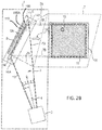
- FIG. 2B aspects of an optical setup as well as the perceptive aspects of illuminations systems as generally described herein are described for a reflective lighting system 1.
- Lighting system 1 comprises again light source 2, configured to emit light in an emission solid angle to form a light beam 3 (in Fig. 1 delimited by dashed lines 13) propagating along a main light beam direction 4 (also referred to as main beam axis).
- light source 2 can be, for example, a cool white light source.
- Exemplary embodiments of light sources may comprise LED based light emitters or discharge lamp based light emitters or hydrargyrum medium-arc iodide lamp based light emitters or halogen lamp based light emitters and respective optical systems downstream of the respective light emitter.
- Illumination system 1 further includes a reflector unit 6 that couples the light originating from light source 2 to a region to be lit up.
- reflector unit 6 comprises a reflective structure 8 providing a reflective surface 8A and chromatic stratified panel structure 100.
- Reflective surface 8A is generally any type of optical acting interface that reflects light having passed through adhesive interlayer 110.
- reflective surface 8A may be a surface of an aluminum layer or an interface between components, such as a reflective coating. Due to reflective surface 8A, light of light beam 3 being incident on reflective surface 8A is redirected to pass again through chromatic stratified panel structure 100, thereafter forming an illuminating light beam 3A (in Fig. 2B delimited by dash-dash-dotted lines 7A).
- Fig. 1 a range 7 of sun-observer locations is illustrated, where it is referred in the wording "sun-observer locations" exemplarily to the "sun” because an especially spectacular type of embodiments of lighting system 1 relates to sun-like illumination.
- Illuminating light beam 3A is, thus, directed in the to be illuminated region and comprises directed light (herein also referred to as directed (light) component of the lighting system).
- Chromatic stratified panel structure 100 is generally configured for emitting diffuse light (later also referred to as diffuse (light) component of the illumination system) at a first color, e.g. in case of a sky imitation a bluish sky color, extends in front of reflective surface 8A, and comprises a visible front area section 100A that an observer can see when looking at reflector unit 6.
- a frame-like area 14A of a frame structure 14 extends next to and surrounding visible front area section 100A.
- the first color and the second color may be separated in the CIE 1976 (u',v') color space by, at least 0.008 such as at least 0.01, 0.025, or 0.04, where the color difference ⁇ u'v' is defined as the Euclidean distance in the u'v' color space.
- the illuminating light beam CCT of the second color may be close to the Planckian locus (e.g. in the range from 800 K to 6 500 K).
- the second color may correspond to u'v' points with a maximum distance from the Planckian locus of e.g. 0.06.
- a distance from the Planckian locus is, for example in the range from 800 K to 6500 K, given by ⁇ u'v' ⁇ 0.060.
- the color and/or CCT of light beam 3 and illuminating light beam 3A may be essentially identical or may differ.
- the CCT difference may be, for example, at least 300 K or even 1 000 K or more.
- an observer may have an optical perception as schematically indicated in Fig. 2B within range 7.
- the optical perception essentially depends on reflector unit 6 and the light coming therefrom as illustrated by dash-dotted lines 7B being specific for the respective observer position.
- lighting system 1 is configured such that light of significant intensity incident within range 7 of sun-observer locations originates from chromatic stratified panel structure 100.
- the light of significant intensity comprises light of light beam 3A (originating from light source 2 and being light of light beam 3 redirected by reflector unit 6), and diffuse light originating from visible front area section 10A.
- the optical perception will - for the embodiment of Fig. 1 - comprise a, for example dark colored, frame-like area 18 around visible front area section 100A.
- the observer when looking from within range 7 of sun-observer locations onto reflector unit 6, will see a large area 16 corresponding to visible front area section 10A based on the homogenously emitted diffuse light at the first color. Large area 16 will be surrounded by frame-like area 18. In addition, the observer will see a sun-like spot 19 at the second color caused by the a reflected (directed non-diffuse) component of the light of light source 2, specifically of illuminating light beam 3A.
- Nanoparticle-based Rayleigh-like diffusing material used in the chromatic stratified panel comprises a solid matrix of a first material (e.g. resins having excellent optical transparency), wherein nanoparticles of a second material (organic or inorganic nanoparticles such as ZnO, TiO2, SiO2, Al2O3 and similar) are dispersed.
- a first material e.g. resins having excellent optical transparency
- nanoparticles of a second material organic or inorganic nanoparticles such as ZnO, TiO2, SiO2, Al2O3 and similar
- the refractive indexes of the two materials are different, and this mismatch on the refractive index on the nano-scale is responsible of the Rayleigh-like scattering phenomenon.
- the absorption of the first and the second material in the visible wavelength range can be considered negligible.
- the chromatic stratified panel 100 may be uniform, in the sense that, given any point of the chromatic stratified panel, the physical characteristics of the panel in that point does not depend on the position of that point.
- the nanoparticles may be monodisperse or polydisperse, they may be spherically shaped or shaped otherwise.
- the effective diameter d of the nanoparticles falls within the range [5 nm-350 nm], such as [10 nm-250 nm], or even [40 nm-180 nm], or [60 nm-150 nm], where the effective diameter d is the diameter of the equivalent spherical particle, namely the effective diameter spherical particle having similar scattering properties as the aforementioned nanoparticles.
- Diameter, refractive index mismatch and areal density (number per square meter) of the nanoparticles are the parameters that define the cross section of the scattering phenomenon in the chromatic panel.
- the amount of the impinging light scattered from the chromatic panel increases by increasing one of the parameters mentioned above.
- T( ⁇ ) the regular transmittance property of the material at a certain wavelength.
- the transmittance is in general the ratio of the transmitted flux to the incident flux in the given conditions.
- the regular transmittance T( ⁇ ) is the transmittance under the undiffused angle, i.e . the angle of incidence.
- the regular transmittance is intended for non-polarized incident light with an incident angle corresponding to the main light beam propagation.
- the range would be [0.3-0.9], such as [0.35-0.85] or even [0.4-0.8]; in the embodiments aiming at a Nordic sky the range would be [0.05-0.3], such as [0.1-0.3] or even [0.15-0.3]. Since the transmittance measurement is a feasible way to evaluate the optical properties of the presented materials, herein this approach is applied similarly to the reflective chromatic stratified panels.
- the mirror coating has to be removed.
- the regular transmittance for the blue T[450 nm] of a chromatic stratified panel before the mirroring of the outer surface may be in general within the range [0.2-0.95].
- the range would be [0.55-0.95], such as [0.6-0.92] or even [0.62-0.9]; in the embodiments aiming at a Nordic sky the range would be [0.2-0.55], such as [0.3-0.55] or even [0.4-0.55].
- the transmittance of a pure clear sky is higher than the one of a Nordic sky.
- the chromatic properties in the sun-sky effect will be different.
- the sky in the Nordic configuration will be whitish compared to the one in the pure clear sky.
- the sun in the Nordic configuration will be more yellow than the one in the pure clear sky.
- the chromatic effect is further based on nanoparticles having a refractive index that is different than the refractive index of the embedding matrix.
- the nanoparticles have a real refractive index n p sufficiently different from that of the matrix n h , (also referred to as host material) in order to allow light scattering to take place.
- the ratio m between the particle and host medium refractive indexes may be in the range 0.5 ⁇ m ⁇ 2.5 such as in the range 0.7 ⁇ m ⁇ 2.1 or 0.7 ⁇ m ⁇ 1.9.
- the chromatic effect is further based on the number of nanoparticles per unit area seen by the impinging light propagating in the given direction as well as the volume-filling-fraction f .
- filling fractions f ⁇ 0.4 such as f ⁇ 0.1, or even f ⁇ 0.01.
- d [meter] is the average particle size defined as the average particle diameter in the case of spherical particles, and as the average diameter of volume-to-area equivalent spherical particles in the case of non-spherical particles, as defined in [ T.C. GRENFELL, AND S.G. WARREN, "Representation of a non-spherical ice particle by a collection of independent spheres for scattering and absorption of radiation". Journal of Geophysical Research 104, D24, 31,697-31,709. (1999 )].
- the effective particle diameter is given in meters or, where specified in nm.
- a light beam passing through a diffusive coating will generate scattered light and transmitted light.
- the coating features can modify both the spectral properties and the intensity distribution of the transmitted light.
- the morphology of the coating i.e. flatness, smoothness or orange peel
- a phase variation which implies a modulation of the intensity distribution of the transmitted light.
- the uniformity in the transmission of an illumination profile is an important feature, if not a feature of paramount importance.
- the inventors realized that, when considering a rough (non-planar on a small scale) surface, the phase variation for a light beam increases by increasing the index mismatch between the two media separated by the rough surface. If a coating is exposed to the air, then the mismatch is the one between the coating and the refractive index of air. The inventors realized that a reduction of the refractive index mismatch will decrease the phase variation, and thus it will increase the uniformity in transmission (double transmission in the case of reflective configurations).
- the inventors suggest herein inter alia a configuration for a flat transparent support coated with a diffusive paint in which any modifications and distortions of a light beam passing through the coating is reduced due to refractive index adaptation.
- a glass sheet 202 is coated with a nanoparticle loaded (hereinafter nano-loaded) diffusive paint 208 (herein also referred to as coating when its dry form is considered).
- nano-loaded diffusive paint 208 herein also referred to as coating when its dry form is considered.
- a transparent adhesive polymeric layer 206 (such as a PVB, EVA or similar) is sandwiched between this coated glass 202 and another glass sheet 204 wherein coating 208 is in contact with adhesive layer 206.
- adhesive layer 206 joins the two glass sheets 202, 204.
- the refractive index mismatch between coating 208 and adhesive layer 206 is much lower than the one that would be present between coating 208 and the air and further considering that the flatness of an outer surface of the glass sheets 202, 204 can be achieved much higher than the one achievable with a coating, the intensity profile of a light beam 3 passing through this stratified glass panel structure remains almost unmodified.
- a transparent adhesive polymeric layer 206 (such as a PVB, EVA or similar) is coated with nano-loaded diffusive paint 208.
- Transparent adhesive polymeric layer 206 is then sandwiched between two glass sheets 202, 204. Through a lamination process, adhesive layer 206 joins the two glass sheets 202, 204. Again, light beam 3 passing through this stratified glass panel structure remains almost unmodified in terms of intensity distribution.
- the result for both process can be, for example, a safety dichroic glass sheet with the structure as shown in Fig. 1 .
- the diffusing layer may be protected against atmospheric agents like UV light, dust, humidity and so on, which could change the chromatic and optical properties of the diffusing layers.
- the panel may be strong enough in order to fulfill architectural requirements such as fire resistance, shock resistance, scratch resistance and the like.
- a typical lamination process of a pair of, for example, 3 mm thick glass sheets and one commercial EVA film in-between the glass sheets starts with bringing the layers in close contact. That assembly is then introduced, for example, in a plastic bag and a low vacuum is applied to the system in order to remove any air in the bag.
- the vacuum-packed bag can then be introduced in an oven and the temperature be raised to 85 °C (with a raising rate of, for example, 3.5°C/min).
- the assemble is maintained at that temperature for about 10 min.
- the temperature is further raised to about 125°C (raising rate 3.5°C/min) and maintained at that temperature for about 30 min.
- the assembly is than cooled to room temperature in, e.g. about 20 min and the stratified glass panel structure is removed from the plastic bag.
- Figs. 4A to 4C starting points of a lamination process is illustrated for a chromatic stratified panel structure with two nano-loaded diffusive coatings 306.
- the layers of nano-loaded diffusive coatings 306 are separated by a transparent adhesive polymeric layer 308.
- the starting point of the lamination process can be based on two glass sheets 302, 304 each coated with a nano-loaded diffusive paint 306 at their inner surfaces ( Fig. 4A ).
- both sides of transparent adhesive polymeric layer 308 may be coated ( Fig. 4C ) or one side of one of the glass sheets 302, 304 and transparent adhesive polymeric layer 308 may be coated ( Fig. 4B ).
- the panel structure generally comprises three main free stranding (self-supporting) components suitable for coating purposes (herein also referred to as support layer) so that at four internal surfaces need to be joined. This allows up to four internal surfaces being coated with nano-loaded diffusive paint 306, wherein all layers together provide the desired Rayleigh-like scattering effect. In configurations having multiple surfaces coated, the randomness in layer thickness of the various coatings may reduce the overall variations in thickness of the combined layers such that the uniformity with respect to the Rayleigh-like scattering process over the panel structure can be increased.
- glass sheets may be used such as normal float glass, tempered, Anti Reflective (AR) coated glass, surface etched glass and similar.
- AR Anti Reflective
- one of the two external glass surfaces of the stratified panel structure may be provided with a reflective coating (i.e . aluminum coating).
- etching solution comprising hydrofluoric acid as an active component.
- Different parameters can affect the final results of etching process for example the composition of the etching liquid, the reaction time and temperature, the application method of the etching liquid, the surface quality of the glass and the glass composition .
- a similar process involving the use of etching cream based on fluoride compounds has been developed in order to minimize problems of toxicity and safety related with the handling of Hydrofluoric Acid.
- An alternative technique often used commercially is based on the mechanical abrasion of the glass surface -Abrasive Blasting or Sandblasting.
- air under high pressure, mixed with an abrasive material is directed towards the glass surface.
- a deep cut is formed to create the desired custom etched glass.
- a less common method involve the use of a mold in a process called Mold Etching.
- the glass is formed inside a structured mold, when removing the glass, it will have the shape and roughness of the mold. This is one of the cheapest methods in the glass industry.
- the terms "paint”, “coating” and “film” refer, in contrast to the term “adhesive polymeric layer”, to a layer that is/needs to be applied on a support structure.
- the “adhesive polymeric layer” is considered an independent structural unit.
- a paint may be a clear material that is applied in liquid form on a surface and after a time produces a dry adherent film. Paint is essentially composed of a binder, particles, and a solvent.
- Binder refers to the non-volatile portion of the vehicle of a coating material that binds the particles together and the film as a whole to the support substrate. Binders can include synthetic or natural resins and can further be classified according to the mechanisms for drying or curing.
- Particles refers to a material, usually with nano or micrometric size that is practically insoluble in the medium and commonly used because of its optical, protective or decorative properties. Particles are broadly classified as either organic or inorganic.
- a solvent refers to a liquid, single or blended, which is volatile under normal drying conditions and in which the binder is soluble.
- Additional components of a paint may be thinners (a volatile liquid, able to facilitate application), catalysts, thickeners, stabilizers, flatteners, emulsifiers, adhesion promoters, UV stabilizers etc.
- thinners a volatile liquid, able to facilitate application
- catalysts a volatile liquid, able to facilitate application
- thickeners a volatile liquid, able to facilitate application
- stabilizers a volatile liquid, able to facilitate application
- flatteners emulsifiers
- adhesion promoters esion promoters
- UV stabilizers etc.
- a primer can be used before application.
- the herein disclosed paints/coatings/films can be made by using as a binder an organic polymer commonly used in industry such as polystyrene, polyurethane, acrylics, alkyd polymer, polyester, siloxane-containing polymer, epoxy-containing polymer etc or a combination of them.
- organic polymer commonly used in industry
- a diluting agent can be added, including water or organic (i.e . alcohol, ethers, ketone, esters, aliphatic and aromatic hydrocarbons or others) acting as solvent.
- solvent commonly employed in the coating industries include, for example, xylene, hexane, acetone, diethyleneglycol, and isopropyl alcohol.
- binder and the relative amount of components added in the resulting paint mixture will depend on several parameters such as the glass surface properties, the application method, and the interaction of the coating with the adhesive layer during the lamination process.
- the material for the nanoparticles or their core may be made with one or more materials that essentially do not absorb light in the visible range having an organic or inorganic nature.
- the inventors are referring to polymers (optionally crosslinked) while in the second case preferably to metal oxides (e.g. TiO2, SiO2, ZnO, ZrO2, Fe2O3, Al2O3, Sb2SnO5, Bi2O3, CeO2 or a combination thereof) with a single phase structure or a core/shell structure.
- the external surface of the nanoparticle core is preferably functionalized with a specific organic coating in order to guarantee an optimal compatibility and dispersion in the paint matrix.
- a poor compatibility of nanoparticles with the paint matrix may lead to the formation of large aggregate/agglomerates and inhomogeneous distribution that will strongly affect the scattering properties of the diffusing coating and consequently of the resulting embodiment.
- the particle sizes may be selected to obtain the required chromatic properties.
- diameter size may be between about 5 nm to 250 nm such as between 20 nm and 150 nm.
- Functionalized nanoparticles may be introduced directly in the binder/solvent mixture or in the paint with the desired final composition.
- the dispersion process may use low/high shear mixing equipment such as magnetic stirrer and/or static mixers.
- the coating can be applied on the glass or directly on the adhesive polymeric layer by commonly used processes such as dip coating, spray coating, inkjet coating, electrodeposition, serigraphy and similar.
- suitable materials mainly include that one typically employed in the stratification industry such as transparent thermoplastic materials (TPU or PVB, EVA) or transparent thermoset material (EVA). At present EVA and PVB covered almost 100% of the production of the stratified glass.
- EVA PolyEthylene-vinyl acetate, is the copolymer of ethylene and vinyl acetate. The weight percent vinyl acetate usually varies from 10% to 40%, with the remainder being ethylene. Different mechanical/adhesive and chemical properties varying depending on the ratio between ethylene and vinyl acetate employed during the synthetic process. The main advantages of EVA are related to its excellent transparency, good adhesion and compatibility, resistance to humidity and long term reliability.
- PVB Poly(Vinyl Butyral) is prepared from polyvinyl alcohol by reaction with butyraldehyde. Elasticity, mechanical strength, toughness, high light transmission and the adhesion to glass are the most significant PVB properties.
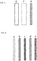
- G represents a glass panel (or generally a light transmitting panel)
- F represents a microstructured surface glass (i.e. a support material with one side being provided with a microstructure)
- A represents an adhesive polymer layer.
- G i o and F i o "j" refers to the outer side, "o", and "i" to the inner side, "i”.
- the syntax is based on coating types shown in Fig. 6 that include a nanoparticle-based Rayleigh-like diffusing coating (a), a microparticle-based diffusing coating (b), a coating combining nanoparticle-based Rayleigh-like diffusing and microparticle-based diffusing (c), an antireflective coating (d), and a mirror (reflective e.g. in the visible) coating (e).
- the nanoparticle-based Rayleigh-like diffusing coating (a) has been described before with respect to its scattering features.
- microparticle-based diffusing coating (b) is obtained with the same procedure stated above in the case of nanoparticles diffusing coating but adding particles with a micrometric size instead of nanometric size. More specifically the desired particles size range is comprised between 1 ⁇ m to 20 ⁇ m. Materials composing the particles can have organic or inorganic nature, in the first case we refer mainly to polymers while in the second case to metal oxide or similar preferably not absorbing in the visible. As in the case of nanoparticles, additional functionalization can also be included on the microparticle's surface in order to increase the compatibility between the particles and the transparent paint.
- Microparticles may be present in an amount of about 1 to about 40% (w/w) with respect to the binder.
- the resulting coating after paint dry may have a thickness of about 2 ⁇ m to about 100 ⁇ m. These particles are beyond of the Rayleigh scattering regime because of their size. Both the chromatic and the distribution intensity of the light scattered by these microparticles are different to the one scattered by the nanosized particles. The spectrum and the intensity of the scattered light is strongly dependent to the scattering angle. In general, considering a sample of microparticles not perfectly monodispersed, the scattered light will be mostly forward scattered without any dependence on the wavelength. By increasing the microparticles size, the scattering angle (the cone angle defined by the intensity profile of the forward scattering) becomes narrower. The microparticle diffusive layer provokes a blurry effect on the panel.
- the coating (c) combines the nanoparticle-based Rayleigh-like diffusing features and the microparticle-based diffusing features.
- the antireflective coating (d) is a physico-chemical surface treatment that allows increasing the regular transmittance of a material. This treatment has to be optimized on a defined wavelength range (visible range for the present application) and strongly depends on the optical properties of the materials facing the antireflective coating.
- An antireflective coating optimized for the interface glass-air in the visible spectrum makes the panels shown in Fig. 2 more efficient in terms of transmittance and decrease the intensity of the reflected scene.
- the mirror coating (e) can be applied on the outer surface of the stratified panels in order to obtain high quality surface chromatic stratified mirror.
- a typical way to produce mirror is to deposit metals such as aluminum or silver on a glass surface. The reflection efficiency depends on the deposited material and the quality of the reflected image depends on the flatness/roughness of the glass.
- the various surfaces defined for the support materials A , G , and F can be coated, for example, with the following coating types:
- l r can be (a), (b), or (c).
- G i o can be (a), (b), or (c), while “o” can be (b), (d) or (e).
- F i o identifies that the microstructure is located on the external side while F ⁇ o ⁇ identifies that the structure is located on the internal side.
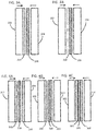
- FIGs. 7A to 7F illustrate exemplary sandwich structures.
- Figs. 7A and 7B correspond to Figs. 3A and 3B , respectively.
- Fig. 7C illustrates a sandwich structure having a microstructure on one outer surface.
- a microstructure surface has the effect of blurring the perceived scene behind the microstructure surface. This property may be desired because those objects seen through (unwanted structures beyond) and virtual images on the panel (reflected images coming from objects of the scene) will be perceived blurry. Accordingly, the variation of the luminance - typical in an observed surface - may originally have sharp edges but can be smoothed by the microstructure surface based, thereby enhancing the depth perception.
- Fig. 7D illustrates a structure similar to Fig. 4B , wherein one nanoparticle-based Rayleigh-like diffusing coating is replaced with a microparticle-based diffusing coating such that forward scattering and a respective blurring effect is introduced.
- Fig. 7E illustrates a sandwich structure having a microstructure on one outer side and an antireflective coating on the inner side.
- the antireflective coating allows, for example, increasing the transmittance of the panel, thereby making the lighting system more efficient.
- Fig. 7F illustrates a sandwich structure having a mirror coating on one outer side. This configuration can be used in the reflection mode as the lighting system described in connection with Fig. 2B .
- a generic three layer structure is disclosed that incorporates the nanoparticle-based Rayleigh like scattering within the adhesive layer. Accordingly, the embodiments are modified in that the diffusing property of the diffusing layer is transferred from a separate coating, being applied e.g. on the interface surfaces including on the side wall of a stand alone adhesive polymeric layer, to being directly inside in the polymeric adhesive layer.
- those new embodiments comprises a stratified-glass panel structure composed of two float glass sheets 104 and 106 sandwiching, and affixed to each other, by way of an adhesive transparent polymeric layer (e.g. an EVA, PVB layer or similar) that is loaded with nanoparticles.
- an adhesive transparent polymeric layer e.g. an EVA, PVB layer or similar
- the adhesive polymeric layer can - in addition to nanoparticles - be loaded with (larger) microparticles together.
- the modified adhesive transparent polymeric layer is herein referred to as nanoloaded adhesive polymeric layer.
- a nanoloaded adhesive polymeric layer may be obtained by different processes available in the industry. One possible process may comprise melting of a solid thermoplastic resin in an extruder followed by addition of the desired amount of nanoparticles. After blending the two component, the mixture is extruded in sheet form with the desired thickness. The method may further comprises pre-mixing the solid thermoplastic resin and the nanoparticles prior to melting the solid thermoplastic resin.
- a second type of process may comprise a direct dissolution and mixing of the nanoparticles with monomers (the simplest unit, or the repeating unit, of a polymer) prior of the polymerization process. This process can lead to a higher degree of dispersion of the nanoparticles even though it has some drawback for the scale up in an industrial plant.
- the adhesive polymeric layer may be based on suitable materials including those that are typically employed in the stratification industry such as transparent thermoplastic materials (TPU or PVB, EVA) or transparent thermoset material (EVA).
- suitable materials including those that are typically employed in the stratification industry such as transparent thermoplastic materials (TPU or PVB, EVA) or transparent thermoset material (EVA).
- Nanoparticles and microparticles features are the same as previously stated for the nanoparticle coating.
- nanoparticle dispersion In order to maintain a good nanoparticle dispersion inside the polymeric adhesive layer, and consequently in the final stratified structure, it may be convenient to modify the surface structure of the nanoparticles itself with a specific agent (molecule, polymer etc.) able to guarantee a good compatibility between the particles and the polymeric layer.
- a specific agent molecule, polymer etc.
- microparticles may be added during the mixing process together with the nanoparticles.
- the inner sandwiched material i.e. the "adhesive polymeric layer” used for incorporating the nanoparticle for the Rayleigh-like diffusing, is referred to in the syntax introduced above as NA.
- the inner sandwiched material "adhesive polymeric layer” may be used for incorporating microparticles for diffusing light - additionally to the nanoparticles for the Rayleigh-like diffusing.
- that layer is referred to as NA'.
- Respective support structures are schematically indicated in Fig. 8 similar to Fig. 5 , which also illustrates the glass panels G and F .
- the outer surfaces defined for the materials can be coated, for example, with an antireflective coating (d), and a mirror (reflective e.g. in the visible) coating (e).
- FIGs. 9A to 9E illustrate exemplary sandwich structures.
- the embodiments of Figs. 9A and 9B correspond to simple three-layer structures without and with a microstructured outer surface, respectively.
- Fig. 9C combines Rayleigh-like scattering features with forward scattering features.
- Fig. 9D uses microstructure at the inner side of one of the glass panels for diffusing, thereby also strengthening the adhesion between NA and that glass panel.
- an outer side is coated with an antireflecting coating to e.g. suppress any back scattering from the background.
- Fig. 9E relates to the reflective lighting system configurations and uses a coating combining nanoparticle-based Rayleigh-like diffusing and microparticle-based diffusing to similarly suppress any back scattering from the background. It is noted that only exemplary configurations are illustrated in Figs. 7A to 7F and Figs. 9A to 9E . Further embodiments are identifiable based on the present disclosure.
- the structural elements based on the above considerations such as the ones illustrated in Figs. 9A to 9E may be subject to a lamination process as described above (illustrated schematically by arrows in the drawings).
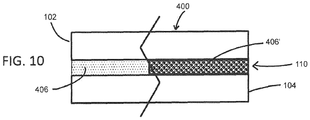
- Fig. 10 schematically shows a resulting chromatic stratified panel structure 400e.g. for generating a sun-sky-imitating effect in lighting systems.
- Chromatic stratified panel 400 comprises two cover panels 102, 104, at least one of which being a transparent panel and/or having a microstructure surface at one side.
- Chromatic stratified panel 400 comprises further as an interlayer 110, an adhesive transparent polymeric layer 406 (left side of the embodiment illustrated in Fig. 10 ) as described above or a modified adhesive polymeric layer 406' incorporating microparticles for diffusing light in additionally to the nanoparticles for the Rayleigh-like diffusing (right side of the embodiment illustrated in Fig. 10 ) as also described above.
- the adhesive polymeric layers 406 , 406' are sandwiched between the two inner faces of the two cover panels 102, 104. Moreover, they may be essentially transparent in the visible.
Landscapes
- Chemical & Material Sciences (AREA)
- Engineering & Computer Science (AREA)
- Physics & Mathematics (AREA)
- General Engineering & Computer Science (AREA)
- Dispersion Chemistry (AREA)
- Chemical Kinetics & Catalysis (AREA)
- Organic Chemistry (AREA)
- Life Sciences & Earth Sciences (AREA)
- Materials Engineering (AREA)
- General Chemical & Material Sciences (AREA)
- Geochemistry & Mineralogy (AREA)
- Spectroscopy & Molecular Physics (AREA)
- General Physics & Mathematics (AREA)
- Optics & Photonics (AREA)
- Composite Materials (AREA)
- Ceramic Engineering (AREA)
- Optical Elements Other Than Lenses (AREA)
- Non-Portable Lighting Devices Or Systems Thereof (AREA)
- Laminated Bodies (AREA)
Claims (14)
- Système d'éclairage (1) comprenant :une source lumineuse (2) configurée pour générer un faisceau lumineux visible (3) ;une structure de panneau stratifié chromatique éclairée par la source lumineuse (2),une partie du faisceau lumineux formant un faisceau lumineux d'éclairage (3A) en passant à travers la structure de panneau stratifié chromatique essentiellement non diffusée, et une partie du faisceau lumineux étant diffusée selon une diffusion de type Rayleigh par des nanoparticules comprises dans la structure de panneau stratifié chromatique, etla structure de panneau stratifié chromatique étant choisie parmi l'un des éléments suivants :- une structure de panneau stratifié chromatique (100) pour générer un effet d'imitation du ciel et du soleil dans des systèmes d'éclairage (1), le panneau stratifié chromatique (100) comprenant :deux panneaux de protection (102, 104), dont au moins un panneau transparent ;une couche adhésive polymère transparente (106) prise en sandwich entre les deux faces intérieures des deux panneaux de protection ; etau moins un revêtement diffusant de type Rayleigh à base de nanoparticules (108) appliqué sur une face intérieure d'au moins l'un des deux panneaux de protection (102, 104) et/ou sur une face de la couche polymère transparente adhésive (106) et formant une couche intermédiaire entre un des panneaux de protection (102, 104) et la couche polymère transparente adhésive (106) ;- une structure de verre stratifié chromatique (100) comprenant :deux feuilles de verre (102, 104) ; etune couche polymère transparente adhésive (106) prise en sandwich entre les deux feuilles de verre (102, 104),la face de l'une des deux feuilles de verre (102, 104) faisant face à la couche polymère adhésive (106) étant revêtue d'une peinture (108) chargée de nanoparticules en tant que couche intermédiaire diffusante de type Rayleigh pour la lumière visible qui diffuse de préférence des composantes à courte longueur d'onde de la lumière incidente par rapport aux composantes à longueur d'onde de la lumière incidente ; et- une structure de verre stratifié chromatique (100) comprenant :deux feuilles de verre (102, 104) ; etune couche polymère adhésive transparente (106) prise en sandwich entre les deux feuilles de verre,la couche polymère adhésive (106) étant revêtue d'une peinture (108) chargée de nanoparticules agissant en tant que couche intermédiaire diffusante de type Rayleigh pour la lumière visible qui diffuse de préférence des composantes à courte longueur d'onde de la lumière incidente par rapport aux composantes à longue longueur d'onde de la lumière incidente.
- Système d'éclairage selon la revendication 1, une première couleur de la lumière diffusée du type Rayleigh et une seconde couleur de la lumière directe diffusée qui n'est pas essentiellement du type Rayleigh étant séparées dans l'espace coloré u'v' d'au moins 0,008, comme au moins 0,02 ou 0,03 ; et/ou
une température de couleur en corrélation directe avec la lumière étant proche de la température de couleur du corps noir, par exemple dans la plage de 800 K à 6500 K ; et/ou
une première couleur étant associée à une température de couleur corrélée à la lumière diffuse qui est différente, en particulier supérieure, à la température de couleur corrélée à la lumière directe du faisceau lumineux ; et/ou
une température de couleur directement corrélée à la lumière différant d'une température de couleur diffuse corrélée à la lumière d'un facteur de 0,85 ou moins. - Système d'éclairage selon la revendication 1 ou 2,
la diffusion de type Rayleigh se rapportant à une lumière ayant un spectre de longueur d'onde s'étendant dans le spectre visible, par exemple, sur au moins 150 nm ; et
le revêtement diffusant de type Rayleigh (108) ayant été appliqué sous la forme d'une peinture comprenant une dispersion de centres de diffusion de lumière d'une taille moyenne inférieure à 250 nm, ayant éventuellement un pic à des tailles de particules inférieures à 250 nm dans la distribution de taille des particules. - Système d'éclairage selon l'une quelconque des revendications précédentes,
deux revêtements (108) chargés de nanoparticules agissant en tant que couche intermédiaire diffusante de type Rayleigh, chacun étant prévu sur un côté de la couche polymère transparente adhésive (106) et du panneau de protection/feuille de verre voisin (102, 104). - Système d'éclairage selon l'une quelconque des revendications précédentes, le nombre N de nanoparticules agissant en tant que diffuseurs de type Rayleigh par surface unitaire de la couche intermédiaire de diffusion chromatique en fonction d'un diamètre effectif de particules D = dnh , d étant la taille moyenne des nanoparticules et nh étant l'indice de réfraction du revêtement ou de la peinture, respectivement, étant dans le domaine défini par


- Système d'éclairage selon l'une quelconque des revendications précédentes, le système comprenant en outre au moins un revêtement diffusant à base de nanoparticules de type Rayleigh (a), un revêtement diffusant à base de microparticules (b), un revêtement combinant un revêtement diffusant à base de nanoparticules de type Rayleigh (c), un revêtement antireflet (d), et un revêtement miroir (e).
- Système d'éclairage selon l'une quelconque des revendications précédentes,
au moins l'un des deux panneaux de protection/feuilles de verre (102, 104) et la couche polymère transparente adhésive (106) comprenant un revêtement diffuseur de petit angle à base de nanoparticules. - Système d'éclairage selon l'une quelconque des revendications précédentes,
un revêtement réfléchissant ou antiréfléchissant étant appliqué sur une face extérieure (o) d'au moins l'un des deux panneaux de protection ou feuilles de verre (102, 104) ; ou
un revêtement réfléchissant formant une couche intermédiaire entre l'un des deux panneaux de protection/feuilles de verre (102, 104) et la couche polymère transparente adhésive (106). - Système d'éclairage (1) comprenant :une source lumineuse (2) configurée pour générer un faisceau lumineux visible (3) ;une structure de panneau stratifié chromatique éclairée par la source lumineuse (2),une partie du faisceau lumineux formant un faisceau lumineux d'éclairage (3A) en passant à travers la structure de panneau stratifié chromatique essentiellement non diffusée, et une partie du faisceau lumineux étant diffusée selon une diffusion de type Rayleigh par des nanoparticules comprises dans la structure de panneau stratifié chromatique, etla structure de panneau stratifié chromatique (400) comprenantdeux panneaux de protection (102, 104) dont l'un au moins est un panneau transparent et/ou ayant une surface micro-structurée sur un côté ; etune couche polymère transparente adhésive (406, NA), la couche polymère transparente adhésive (406, NA) étant prise en sandwich entre les deux faces intérieures des deux panneaux de protection,la couche polymère transparente adhésive (406, NA) comprenantune couche polymère (106) configurée pour agir en tant que structure de base adhésive pendant un processus de durcissement, la couche polymère (106) comprenant des nanoparticules pour la diffusion de lumière visible de type Rayleigh, le nombre N de nanoparticules agissant en tant que diffuseurs de type Rayleigh par surface unitaire de la couche diffusive chromatique en fonction d'un diamètre effectif des particules D = d nh , d étant la taille moyenne des particules et nh l'indice de réfraction du polymère, se trouvant dans la plage défini par


- Système d'éclairage selon l'une quelconque des revendications précédentes, le nombre N de nanoparticules agissant en tant que diffuseurs de type Rayleigh par surface unitaire étant destiné à des réalisations visant à simuler la présence d'un ciel pur et clair :


pour des modes de réalisation visant à simuler un ciel nordique :


- Système d'éclairage selon l'une quelconque des revendications 1 à 9, le nombre N de nanoparticules agissant comme diffuseurs de type Rayleigh par surface unitaire étant
pour des réalisations visant à simuler la présence d'un ciel pur et clair :


pour des modes de réalisation visant à simuler un ciel nordique :


- Système d'éclairage selon l'une quelconque des revendications précédentes, les panneaux de protection (102, 104) étant configurés comme matériaux de support transmettant la lumière, ou
les panneaux de protection (102, 104) comprenant une feuille de verre ou un panneau de verre ou un verre de surface micro-structurée ayant sur un côté une microstructure. - Système d'éclairage selon l'une quelconque des revendications précédentes,
la couche polymère transparente adhésive (106) étant autoportante pour former une structure de support pour un revêtement, ou étant élastique, ou son matériau étant choisi dans le groupe des matériaux polymères comprenant des matériaux thermoplastiques transparents. - Système d'éclairage selon l'une quelconque des revendications 9 à 13,
la couche polymère transparente adhésive (NA) comprenant un revêtement diffuseur de petit angle à base de microparticules ; ou
un revêtement réfléchissant ou un revêtement antiréfléchissant étant appliqué sur une face extérieure (o) d'au moins l'un des deux panneaux de protection/feuilles de verre (102, 104).
Priority Applications (1)
| Application Number | Priority Date | Filing Date | Title |
|---|---|---|---|
| EP20150861.1A EP3702151A1 (fr) | 2015-11-19 | 2016-11-15 | Stucture d'un panneau stratifié pour des systèmes d'éclairage imitant le ciel ensoleillé |
Applications Claiming Priority (2)
| Application Number | Priority Date | Filing Date | Title |
|---|---|---|---|
| EP2015077171 | 2015-11-19 | ||
| PCT/EP2016/077770 WO2017085079A1 (fr) | 2015-11-19 | 2016-11-15 | Structure de panneau stratifiée pour systèmes d'éclairage imitant le ciel et le soleil |
Related Child Applications (1)
| Application Number | Title | Priority Date | Filing Date |
|---|---|---|---|
| EP20150861.1A Division EP3702151A1 (fr) | 2015-11-19 | 2016-11-15 | Stucture d'un panneau stratifié pour des systèmes d'éclairage imitant le ciel ensoleillé |
Publications (2)
| Publication Number | Publication Date |
|---|---|
| EP3377317A1 EP3377317A1 (fr) | 2018-09-26 |
| EP3377317B1 true EP3377317B1 (fr) | 2020-01-29 |
Family
ID=57544383
Family Applications (2)
| Application Number | Title | Priority Date | Filing Date |
|---|---|---|---|
| EP16810258.0A Active EP3377317B1 (fr) | 2015-11-19 | 2016-11-15 | Stucture d'un panneau stratifié pour des systèmes d'éclairage imitant le ciel ensoleillé |
| EP20150861.1A Withdrawn EP3702151A1 (fr) | 2015-11-19 | 2016-11-15 | Stucture d'un panneau stratifié pour des systèmes d'éclairage imitant le ciel ensoleillé |
Family Applications After (1)
| Application Number | Title | Priority Date | Filing Date |
|---|---|---|---|
| EP20150861.1A Withdrawn EP3702151A1 (fr) | 2015-11-19 | 2016-11-15 | Stucture d'un panneau stratifié pour des systèmes d'éclairage imitant le ciel ensoleillé |
Country Status (6)
| Country | Link |
|---|---|
| US (1) | US10723103B2 (fr) |
| EP (2) | EP3377317B1 (fr) |
| JP (2) | JP6487605B2 (fr) |
| KR (1) | KR20180084937A (fr) |
| CN (1) | CN109153232B (fr) |
| WO (1) | WO2017085079A1 (fr) |
Families Citing this family (13)
| Publication number | Priority date | Publication date | Assignee | Title |
|---|---|---|---|---|
| WO2017008822A1 (fr) * | 2015-07-15 | 2017-01-19 | Coelux S.R.L. | Système d'éclairage réfléchissant permettant une perception optiquement élargie |
| CN108139044B (zh) | 2015-07-15 | 2021-06-04 | 科勒克斯有限责任公司 | 色彩反射单元 |
| EP3336412B1 (fr) * | 2016-12-13 | 2020-04-08 | CoeLux S.r.l. | Système de simulation de l'apparance de la lune |
| IT201800005634A1 (it) | 2018-05-23 | 2019-11-23 | Struttura a film multistrato cromaticamente diffondente per sistemi di illuminazione simulanti cielo-sole | |
| WO2020196594A1 (fr) * | 2019-03-28 | 2020-10-01 | 三菱電機株式会社 | Diffuseur, unité d'éclairage, et dispositif d'éclairage |
| CN110081378B (zh) * | 2019-04-30 | 2022-02-11 | 青岛亿联客信息技术有限公司 | 一种灯具及照明设备 |
| EP3951259B1 (fr) * | 2019-05-23 | 2024-04-03 | Suzhou Opple Lighting Co., Ltd. | Lampe d'éclairage |
| US11874431B2 (en) | 2019-05-27 | 2024-01-16 | Mitsubishi Electric Corporation | Diffuser and lighting device |
| EP3715108A1 (fr) * | 2019-07-10 | 2020-09-30 | Kuraray Europe GmbH | Intercouche de stratification illuminable et vitrage |
| US11971570B2 (en) | 2019-11-19 | 2024-04-30 | Mitsubishi Electric Corporation | Light diffuser, lighting device, and method of manufacturing light diffuser |
| FR3104489B1 (fr) * | 2019-12-17 | 2021-12-10 | Smart Lite | Assemblage opacifiant pré-laminé pour vitrage |
| CN111506136B (zh) * | 2020-05-06 | 2022-07-19 | 苏州大侎光学科技有限公司 | 一种模拟太阳光及天空背景光照明的光源系统 |
| US11168866B1 (en) * | 2021-04-28 | 2021-11-09 | Longhorn Intelligent Tech Co., Ltd | Rayleigh scatter light |
Family Cites Families (27)
| Publication number | Priority date | Publication date | Assignee | Title |
|---|---|---|---|---|
| JP2000221308A (ja) * | 1999-02-01 | 2000-08-11 | Nitto Denko Corp | 散乱重畳型粘着層、光学部材及び液晶表示装置 |
| AU2004317197B2 (en) * | 2004-03-16 | 2010-09-09 | Sumitomo Metal Mining Co., Ltd. | Sun screening laminated structure |
| GB0711695D0 (en) | 2007-06-16 | 2007-07-25 | Flynn Sean | An infinity display with autostereoscopic capability |
| ITMI20081135A1 (it) | 2008-06-24 | 2009-12-25 | Trapani Paolo Di | Dispositivo di illuminazione |
| US8068285B1 (en) | 2009-05-19 | 2011-11-29 | Sean Thomas Flynn | Infinity display with autostereoscopic capability |
| WO2011047385A1 (fr) * | 2009-10-17 | 2011-04-21 | Qd Vision, Inc. | Composant optique, produits le comprenant et leurs procédés de fabrication |
| CN103718068B (zh) * | 2011-07-01 | 2017-02-22 | 特罗皮格拉斯科技有限公司 | 光谱选择面板 |
| DE112012003937T5 (de) * | 2011-09-21 | 2014-07-17 | Panasonic Corporation | Organisches elektrolumineszentes Element |
| JP5939188B2 (ja) * | 2013-03-28 | 2016-06-22 | 住友金属鉱山株式会社 | 熱線遮蔽用合わせ構造体 |
| KR102109705B1 (ko) * | 2012-06-11 | 2020-05-12 | 스미토모 긴조쿠 고잔 가부시키가이샤 | 열선 차폐용 적층 구조체 |
| CN105431679B (zh) * | 2012-11-14 | 2017-07-04 | 科勒克斯有限责任公司 | 用于产生自然光的人工照明装置 |
| ITTO20120988A1 (it) * | 2012-11-14 | 2014-05-15 | Light In Light S R L | Sistema di illuminazione artificiale per simulare un'illuminazione naturale |
| WO2015036057A1 (fr) * | 2013-09-16 | 2015-03-19 | Light In Light S.R.L. | Système composite comprenant une matrice polymère et des nanoparticules cœur-coquille, son procédé de préparation et son utilisation |
| EP3117142B1 (fr) * | 2014-03-10 | 2020-06-10 | Coelux S.R.L. | Système d'éclairage |
| US10161596B2 (en) | 2014-05-13 | 2018-12-25 | Coelux S.R.L. | Chromatic mirror, chromatic panel and applications thereof |
| US10174890B2 (en) * | 2014-05-13 | 2019-01-08 | Coelux S.R.L. | Light source and sunlight imitating lighting system |
| EP3143344B1 (fr) * | 2014-05-14 | 2020-03-11 | CoeLux S.r.l. | Dispositif d'éclairage simulant l'éclairage naturel et comprenant une source de lumière infrarouge |
| US10088125B2 (en) | 2015-02-23 | 2018-10-02 | Coelux S.R.L. | Illumination system for optically widened perception |
| WO2016143566A1 (fr) * | 2015-03-06 | 2016-09-15 | Jxエネルギー株式会社 | Stratifié transparent, écran transparent le comportant, et dispositif de projection d'image les comportant |
| EP3271418A1 (fr) * | 2015-03-18 | 2018-01-24 | CoeLux S.r.l. | Système composite comprenant une matrice et des éléments de dispersion, procédé de préparation et utilisation correspondante |
| US9904063B2 (en) | 2015-06-15 | 2018-02-27 | Innerscene, Inc. | Collimating display and methods |
| EP4001738A1 (fr) | 2015-09-16 | 2022-05-25 | Innerscene Limited | Lucarne artificielle et procédés |
| ITUB20155577A1 (it) * | 2015-11-13 | 2017-05-13 | Coelux Srl | Sistema di illuminazione che simula l'illuminazione naturale e include una sorgente di luce infrarossa |
| WO2017084756A1 (fr) * | 2015-11-19 | 2017-05-26 | Coelux S.R.L. | Système d'éclairage modulaire imitant le soleil-ciel |
| WO2017090686A1 (fr) * | 2015-11-26 | 2017-06-01 | 旭硝子株式会社 | Verre feuilleté, verre à vitres pour des automobiles et verre à vitres pour des bâtiments |
| IL244633B (en) * | 2016-03-17 | 2020-08-31 | Donval Ariela | Optical limiter depends on temperature, compound and device |
| US10353123B2 (en) * | 2017-08-08 | 2019-07-16 | Apple Inc. | Electronic Devices with glass layer coatings |
-
2016
- 2016-11-15 EP EP16810258.0A patent/EP3377317B1/fr active Active
- 2016-11-15 WO PCT/EP2016/077770 patent/WO2017085079A1/fr active Application Filing
- 2016-11-15 EP EP20150861.1A patent/EP3702151A1/fr not_active Withdrawn
- 2016-11-15 KR KR1020187017285A patent/KR20180084937A/ko unknown
- 2016-11-15 US US15/777,003 patent/US10723103B2/en active Active
- 2016-11-15 JP JP2018526091A patent/JP6487605B2/ja not_active Expired - Fee Related
- 2016-11-15 CN CN201680079390.3A patent/CN109153232B/zh active Active
-
2019
- 2019-02-21 JP JP2019029088A patent/JP2019096622A/ja active Pending
Non-Patent Citations (1)
| Title |
|---|
| None * |
Also Published As
| Publication number | Publication date |
|---|---|
| JP6487605B2 (ja) | 2019-03-20 |
| US20180345630A1 (en) | 2018-12-06 |
| EP3702151A1 (fr) | 2020-09-02 |
| CN109153232A (zh) | 2019-01-04 |
| US10723103B2 (en) | 2020-07-28 |
| EP3377317A1 (fr) | 2018-09-26 |
| JP2019096622A (ja) | 2019-06-20 |
| WO2017085079A1 (fr) | 2017-05-26 |
| KR20180084937A (ko) | 2018-07-25 |
| CN109153232B (zh) | 2021-06-08 |
| JP2019503034A (ja) | 2019-01-31 |
Similar Documents
| Publication | Publication Date | Title |
|---|---|---|
| EP3377317B1 (fr) | Stucture d'un panneau stratifié pour des systèmes d'éclairage imitant le ciel ensoleillé | |
| EP3322932B1 (fr) | Façade chromatique et unités de fenêtre | |
| JP2019096622A5 (fr) | ||
| CN108227168A (zh) | 光偏转与光漫射混合构造 | |
| WO2016068087A1 (fr) | Écran transparent transmettant la lumière, système d'affichage d'image, et procédé d'affichage d'image | |
| JP6508205B2 (ja) | 映像表示透明部材、映像表示システムおよび映像表示方法 | |
| US9939563B2 (en) | Sky-dome lighting system | |
| JP6254101B2 (ja) | ヘッドアップ・ディスプレイ・システムのための熱可塑性シート | |
| WO2009156348A1 (fr) | Diffuseur de soleil optique | |
| JP6974742B2 (ja) | 発光機能を有するガラス窓 | |
| JP2010002825A (ja) | 近赤外線吸収能を有する反射防止材 | |
| JP3235338U (ja) | 晴天模倣照明システム用色彩拡散性多層フィルム構造 | |
| WO2019181368A1 (fr) | Corps de diffusion de lumière, composition pour former un corps de diffusion de lumière, stratifié de type feuille, écran de projection, feuille de diffusion de lumière et dispositif d'éclairage avec amplificateur de lumière intégré | |
| CN102588895A (zh) | 均光抗眩结构及发光装置 | |
| JP2017021296A (ja) | 量子ドットシート、バックライト及び液晶表示装置 |
Legal Events
| Date | Code | Title | Description |
|---|---|---|---|
| STAA | Information on the status of an ep patent application or granted ep patent |
Free format text: STATUS: UNKNOWN |
|
| STAA | Information on the status of an ep patent application or granted ep patent |
Free format text: STATUS: THE INTERNATIONAL PUBLICATION HAS BEEN MADE |
|
| PUAI | Public reference made under article 153(3) epc to a published international application that has entered the european phase |
Free format text: ORIGINAL CODE: 0009012 |
|
| STAA | Information on the status of an ep patent application or granted ep patent |
Free format text: STATUS: REQUEST FOR EXAMINATION WAS MADE |
|
| 17P | Request for examination filed |
Effective date: 20180531 |
|
| AK | Designated contracting states |
Kind code of ref document: A1 Designated state(s): AL AT BE BG CH CY CZ DE DK EE ES FI FR GB GR HR HU IE IS IT LI LT LU LV MC MK MT NL NO PL PT RO RS SE SI SK SM TR |
|
| AX | Request for extension of the european patent |
Extension state: BA ME |
|
| DAV | Request for validation of the european patent (deleted) | ||
| DAX | Request for extension of the european patent (deleted) | ||
| GRAP | Despatch of communication of intention to grant a patent |
Free format text: ORIGINAL CODE: EPIDOSNIGR1 |
|
| STAA | Information on the status of an ep patent application or granted ep patent |
Free format text: STATUS: GRANT OF PATENT IS INTENDED |
|
| INTG | Intention to grant announced |
Effective date: 20190729 |
|
| GRAS | Grant fee paid |
Free format text: ORIGINAL CODE: EPIDOSNIGR3 |
|
| GRAJ | Information related to disapproval of communication of intention to grant by the applicant or resumption of examination proceedings by the epo deleted |
Free format text: ORIGINAL CODE: EPIDOSDIGR1 |
|
| GRAL | Information related to payment of fee for publishing/printing deleted |
Free format text: ORIGINAL CODE: EPIDOSDIGR3 |
|
| STAA | Information on the status of an ep patent application or granted ep patent |
Free format text: STATUS: REQUEST FOR EXAMINATION WAS MADE |
|
| GRAR | Information related to intention to grant a patent recorded |
Free format text: ORIGINAL CODE: EPIDOSNIGR71 |
|
| STAA | Information on the status of an ep patent application or granted ep patent |
Free format text: STATUS: GRANT OF PATENT IS INTENDED |
|
| GRAJ | Information related to disapproval of communication of intention to grant by the applicant or resumption of examination proceedings by the epo deleted |
Free format text: ORIGINAL CODE: EPIDOSDIGR1 |
|
| GRAP | Despatch of communication of intention to grant a patent |
Free format text: ORIGINAL CODE: EPIDOSNIGR1 |
|
| GRAJ | Information related to disapproval of communication of intention to grant by the applicant or resumption of examination proceedings by the epo deleted |
Free format text: ORIGINAL CODE: EPIDOSDIGR1 |
|
| GRAR | Information related to intention to grant a patent recorded |
Free format text: ORIGINAL CODE: EPIDOSNIGR71 |
|
| GRAJ | Information related to disapproval of communication of intention to grant by the applicant or resumption of examination proceedings by the epo deleted |
Free format text: ORIGINAL CODE: EPIDOSDIGR1 |
|
| STAA | Information on the status of an ep patent application or granted ep patent |
Free format text: STATUS: REQUEST FOR EXAMINATION WAS MADE |
|
| GRAR | Information related to intention to grant a patent recorded |
Free format text: ORIGINAL CODE: EPIDOSNIGR71 |
|
| STAA | Information on the status of an ep patent application or granted ep patent |
Free format text: STATUS: GRANT OF PATENT IS INTENDED |
|
| INTG | Intention to grant announced |
Effective date: 20191119 |
|
| GRAA | (expected) grant |
Free format text: ORIGINAL CODE: 0009210 |
|
| STAA | Information on the status of an ep patent application or granted ep patent |
Free format text: STATUS: THE PATENT HAS BEEN GRANTED |
|
| INTC | Intention to grant announced (deleted) | ||
| INTG | Intention to grant announced |
Effective date: 20191202 |
|
| INTG | Intention to grant announced |
Effective date: 20191212 |
|
| INTG | Intention to grant announced |
Effective date: 20191216 |
|
| AK | Designated contracting states |
Kind code of ref document: B1 Designated state(s): AL AT BE BG CH CY CZ DE DK EE ES FI FR GB GR HR HU IE IS IT LI LT LU LV MC MK MT NL NO PL PT RO RS SE SI SK SM TR |
|
| REG | Reference to a national code |
Ref country code: GB Ref legal event code: FG4D |
|
| REG | Reference to a national code |
Ref country code: CH Ref legal event code: EP |
|
| REG | Reference to a national code |
Ref country code: AT Ref legal event code: REF Ref document number: 1228198 Country of ref document: AT Kind code of ref document: T Effective date: 20200215 |
|
| REG | Reference to a national code |
Ref country code: IE Ref legal event code: FG4D |
|
| REG | Reference to a national code |
Ref country code: DE Ref legal event code: R096 Ref document number: 602016028881 Country of ref document: DE |
|
| REG | Reference to a national code |
Ref country code: NL Ref legal event code: MP Effective date: 20200129 |
|
| PG25 | Lapsed in a contracting state [announced via postgrant information from national office to epo] |
Ref country code: PT Free format text: LAPSE BECAUSE OF FAILURE TO SUBMIT A TRANSLATION OF THE DESCRIPTION OR TO PAY THE FEE WITHIN THE PRESCRIBED TIME-LIMIT Effective date: 20200621 Ref country code: NO Free format text: LAPSE BECAUSE OF FAILURE TO SUBMIT A TRANSLATION OF THE DESCRIPTION OR TO PAY THE FEE WITHIN THE PRESCRIBED TIME-LIMIT Effective date: 20200429 Ref country code: FI Free format text: LAPSE BECAUSE OF FAILURE TO SUBMIT A TRANSLATION OF THE DESCRIPTION OR TO PAY THE FEE WITHIN THE PRESCRIBED TIME-LIMIT Effective date: 20200129 Ref country code: RS Free format text: LAPSE BECAUSE OF FAILURE TO SUBMIT A TRANSLATION OF THE DESCRIPTION OR TO PAY THE FEE WITHIN THE PRESCRIBED TIME-LIMIT Effective date: 20200129 |
|
| REG | Reference to a national code |
Ref country code: LT Ref legal event code: MG4D |
|
| PG25 | Lapsed in a contracting state [announced via postgrant information from national office to epo] |
Ref country code: GR Free format text: LAPSE BECAUSE OF FAILURE TO SUBMIT A TRANSLATION OF THE DESCRIPTION OR TO PAY THE FEE WITHIN THE PRESCRIBED TIME-LIMIT Effective date: 20200430 Ref country code: HR Free format text: LAPSE BECAUSE OF FAILURE TO SUBMIT A TRANSLATION OF THE DESCRIPTION OR TO PAY THE FEE WITHIN THE PRESCRIBED TIME-LIMIT Effective date: 20200129 Ref country code: SE Free format text: LAPSE BECAUSE OF FAILURE TO SUBMIT A TRANSLATION OF THE DESCRIPTION OR TO PAY THE FEE WITHIN THE PRESCRIBED TIME-LIMIT Effective date: 20200129 Ref country code: IS Free format text: LAPSE BECAUSE OF FAILURE TO SUBMIT A TRANSLATION OF THE DESCRIPTION OR TO PAY THE FEE WITHIN THE PRESCRIBED TIME-LIMIT Effective date: 20200529 Ref country code: LV Free format text: LAPSE BECAUSE OF FAILURE TO SUBMIT A TRANSLATION OF THE DESCRIPTION OR TO PAY THE FEE WITHIN THE PRESCRIBED TIME-LIMIT Effective date: 20200129 Ref country code: BG Free format text: LAPSE BECAUSE OF FAILURE TO SUBMIT A TRANSLATION OF THE DESCRIPTION OR TO PAY THE FEE WITHIN THE PRESCRIBED TIME-LIMIT Effective date: 20200429 |
|
| PG25 | Lapsed in a contracting state [announced via postgrant information from national office to epo] |
Ref country code: NL Free format text: LAPSE BECAUSE OF FAILURE TO SUBMIT A TRANSLATION OF THE DESCRIPTION OR TO PAY THE FEE WITHIN THE PRESCRIBED TIME-LIMIT Effective date: 20200129 |
|
| PG25 | Lapsed in a contracting state [announced via postgrant information from national office to epo] |
Ref country code: EE Free format text: LAPSE BECAUSE OF FAILURE TO SUBMIT A TRANSLATION OF THE DESCRIPTION OR TO PAY THE FEE WITHIN THE PRESCRIBED TIME-LIMIT Effective date: 20200129 Ref country code: LT Free format text: LAPSE BECAUSE OF FAILURE TO SUBMIT A TRANSLATION OF THE DESCRIPTION OR TO PAY THE FEE WITHIN THE PRESCRIBED TIME-LIMIT Effective date: 20200129 Ref country code: SM Free format text: LAPSE BECAUSE OF FAILURE TO SUBMIT A TRANSLATION OF THE DESCRIPTION OR TO PAY THE FEE WITHIN THE PRESCRIBED TIME-LIMIT Effective date: 20200129 Ref country code: DK Free format text: LAPSE BECAUSE OF FAILURE TO SUBMIT A TRANSLATION OF THE DESCRIPTION OR TO PAY THE FEE WITHIN THE PRESCRIBED TIME-LIMIT Effective date: 20200129 Ref country code: RO Free format text: LAPSE BECAUSE OF FAILURE TO SUBMIT A TRANSLATION OF THE DESCRIPTION OR TO PAY THE FEE WITHIN THE PRESCRIBED TIME-LIMIT Effective date: 20200129 Ref country code: CZ Free format text: LAPSE BECAUSE OF FAILURE TO SUBMIT A TRANSLATION OF THE DESCRIPTION OR TO PAY THE FEE WITHIN THE PRESCRIBED TIME-LIMIT Effective date: 20200129 Ref country code: ES Free format text: LAPSE BECAUSE OF FAILURE TO SUBMIT A TRANSLATION OF THE DESCRIPTION OR TO PAY THE FEE WITHIN THE PRESCRIBED TIME-LIMIT Effective date: 20200129 Ref country code: SK Free format text: LAPSE BECAUSE OF FAILURE TO SUBMIT A TRANSLATION OF THE DESCRIPTION OR TO PAY THE FEE WITHIN THE PRESCRIBED TIME-LIMIT Effective date: 20200129 |
|
| REG | Reference to a national code |
Ref country code: DE Ref legal event code: R097 Ref document number: 602016028881 Country of ref document: DE |
|
| REG | Reference to a national code |
Ref country code: AT Ref legal event code: MK05 Ref document number: 1228198 Country of ref document: AT Kind code of ref document: T Effective date: 20200129 |
|
| PLBE | No opposition filed within time limit |
Free format text: ORIGINAL CODE: 0009261 |
|
| STAA | Information on the status of an ep patent application or granted ep patent |
Free format text: STATUS: NO OPPOSITION FILED WITHIN TIME LIMIT |
|
| 26N | No opposition filed |
Effective date: 20201030 |
|
| PG25 | Lapsed in a contracting state [announced via postgrant information from national office to epo] |
Ref country code: AT Free format text: LAPSE BECAUSE OF FAILURE TO SUBMIT A TRANSLATION OF THE DESCRIPTION OR TO PAY THE FEE WITHIN THE PRESCRIBED TIME-LIMIT Effective date: 20200129 |
|
| PGFP | Annual fee paid to national office [announced via postgrant information from national office to epo] |
Ref country code: DE Payment date: 20201201 Year of fee payment: 5 Ref country code: IT Payment date: 20201130 Year of fee payment: 5 Ref country code: FR Payment date: 20201127 Year of fee payment: 5 Ref country code: GB Payment date: 20201126 Year of fee payment: 5 |
|
| PG25 | Lapsed in a contracting state [announced via postgrant information from national office to epo] |
Ref country code: PL Free format text: LAPSE BECAUSE OF FAILURE TO SUBMIT A TRANSLATION OF THE DESCRIPTION OR TO PAY THE FEE WITHIN THE PRESCRIBED TIME-LIMIT Effective date: 20200129 Ref country code: SI Free format text: LAPSE BECAUSE OF FAILURE TO SUBMIT A TRANSLATION OF THE DESCRIPTION OR TO PAY THE FEE WITHIN THE PRESCRIBED TIME-LIMIT Effective date: 20200129 |
|
| PG25 | Lapsed in a contracting state [announced via postgrant information from national office to epo] |
Ref country code: MC Free format text: LAPSE BECAUSE OF FAILURE TO SUBMIT A TRANSLATION OF THE DESCRIPTION OR TO PAY THE FEE WITHIN THE PRESCRIBED TIME-LIMIT Effective date: 20200129 |
|
| REG | Reference to a national code |
Ref country code: CH Ref legal event code: PL |
|
| PG25 | Lapsed in a contracting state [announced via postgrant information from national office to epo] |
Ref country code: LU Free format text: LAPSE BECAUSE OF NON-PAYMENT OF DUE FEES Effective date: 20201115 |
|
| REG | Reference to a national code |
Ref country code: BE Ref legal event code: MM Effective date: 20201130 |
|
| PG25 | Lapsed in a contracting state [announced via postgrant information from national office to epo] |
Ref country code: CH Free format text: LAPSE BECAUSE OF NON-PAYMENT OF DUE FEES Effective date: 20201130 Ref country code: LI Free format text: LAPSE BECAUSE OF NON-PAYMENT OF DUE FEES Effective date: 20201130 |
|
| PG25 | Lapsed in a contracting state [announced via postgrant information from national office to epo] |
Ref country code: IE Free format text: LAPSE BECAUSE OF NON-PAYMENT OF DUE FEES Effective date: 20201115 |
|
| PG25 | Lapsed in a contracting state [announced via postgrant information from national office to epo] |
Ref country code: TR Free format text: LAPSE BECAUSE OF FAILURE TO SUBMIT A TRANSLATION OF THE DESCRIPTION OR TO PAY THE FEE WITHIN THE PRESCRIBED TIME-LIMIT Effective date: 20200129 Ref country code: MT Free format text: LAPSE BECAUSE OF FAILURE TO SUBMIT A TRANSLATION OF THE DESCRIPTION OR TO PAY THE FEE WITHIN THE PRESCRIBED TIME-LIMIT Effective date: 20200129 Ref country code: CY Free format text: LAPSE BECAUSE OF FAILURE TO SUBMIT A TRANSLATION OF THE DESCRIPTION OR TO PAY THE FEE WITHIN THE PRESCRIBED TIME-LIMIT Effective date: 20200129 |
|
| REG | Reference to a national code |
Ref country code: DE Ref legal event code: R119 Ref document number: 602016028881 Country of ref document: DE |
|
| PG25 | Lapsed in a contracting state [announced via postgrant information from national office to epo] |
Ref country code: MK Free format text: LAPSE BECAUSE OF FAILURE TO SUBMIT A TRANSLATION OF THE DESCRIPTION OR TO PAY THE FEE WITHIN THE PRESCRIBED TIME-LIMIT Effective date: 20200129 Ref country code: AL Free format text: LAPSE BECAUSE OF FAILURE TO SUBMIT A TRANSLATION OF THE DESCRIPTION OR TO PAY THE FEE WITHIN THE PRESCRIBED TIME-LIMIT Effective date: 20200129 |
|
| GBPC | Gb: european patent ceased through non-payment of renewal fee |
Effective date: 20211115 |
|
| PG25 | Lapsed in a contracting state [announced via postgrant information from national office to epo] |
Ref country code: BE Free format text: LAPSE BECAUSE OF NON-PAYMENT OF DUE FEES Effective date: 20201130 |
|
| PG25 | Lapsed in a contracting state [announced via postgrant information from national office to epo] |
Ref country code: GB Free format text: LAPSE BECAUSE OF NON-PAYMENT OF DUE FEES Effective date: 20211115 Ref country code: DE Free format text: LAPSE BECAUSE OF NON-PAYMENT OF DUE FEES Effective date: 20220601 |
|
| PG25 | Lapsed in a contracting state [announced via postgrant information from national office to epo] |
Ref country code: FR Free format text: LAPSE BECAUSE OF NON-PAYMENT OF DUE FEES Effective date: 20211130 |
|
| PG25 | Lapsed in a contracting state [announced via postgrant information from national office to epo] |
Ref country code: IT Free format text: LAPSE BECAUSE OF NON-PAYMENT OF DUE FEES Effective date: 20211115 |
|
| P01 | Opt-out of the competence of the unified patent court (upc) registered |
Effective date: 20230404 |