EP3377012B1 - Vorrichtung zur behandlung einer neurologischen störung des gehörs - Google Patents
Vorrichtung zur behandlung einer neurologischen störung des gehörs Download PDFInfo
- Publication number
- EP3377012B1 EP3377012B1 EP16797535.8A EP16797535A EP3377012B1 EP 3377012 B1 EP3377012 B1 EP 3377012B1 EP 16797535 A EP16797535 A EP 16797535A EP 3377012 B1 EP3377012 B1 EP 3377012B1
- Authority
- EP
- European Patent Office
- Prior art keywords
- stimulus
- somatosensory
- audio signal
- array
- stimulation
- Prior art date
- Legal status (The legal status is an assumption and is not a legal conclusion. Google has not performed a legal analysis and makes no representation as to the accuracy of the status listed.)
- Active
Links
Images


Classifications
-
- A—HUMAN NECESSITIES
- A61—MEDICAL OR VETERINARY SCIENCE; HYGIENE
- A61B—DIAGNOSIS; SURGERY; IDENTIFICATION
- A61B5/00—Measuring for diagnostic purposes; Identification of persons
- A61B5/12—Audiometering
- A61B5/128—Audiometering evaluating tinnitus
-
- A—HUMAN NECESSITIES
- A61—MEDICAL OR VETERINARY SCIENCE; HYGIENE
- A61B—DIAGNOSIS; SURGERY; IDENTIFICATION
- A61B5/00—Measuring for diagnostic purposes; Identification of persons
- A61B5/74—Details of notification to user or communication with user or patient; User input means
- A61B5/7455—Details of notification to user or communication with user or patient; User input means characterised by tactile indication, e.g. vibration or electrical stimulation
-
- A—HUMAN NECESSITIES
- A61—MEDICAL OR VETERINARY SCIENCE; HYGIENE
- A61F—FILTERS IMPLANTABLE INTO BLOOD VESSELS; PROSTHESES; DEVICES PROVIDING PATENCY TO, OR PREVENTING COLLAPSING OF, TUBULAR STRUCTURES OF THE BODY, e.g. STENTS; ORTHOPAEDIC, NURSING OR CONTRACEPTIVE DEVICES; FOMENTATION; TREATMENT OR PROTECTION OF EYES OR EARS; BANDAGES, DRESSINGS OR ABSORBENT PADS; FIRST-AID KITS
- A61F11/00—Methods or devices for treatment of the ears or hearing sense; Non-electric hearing aids; Methods or devices for enabling ear patients to achieve auditory perception through physiological senses other than hearing sense; Protective devices for the ears, carried on the body or in the hand
- A61F11/04—Methods or devices for enabling ear patients to achieve auditory perception through physiological senses other than hearing sense, e.g. through the touch sense
-
- A—HUMAN NECESSITIES
- A61—MEDICAL OR VETERINARY SCIENCE; HYGIENE
- A61M—DEVICES FOR INTRODUCING MEDIA INTO, OR ONTO, THE BODY; DEVICES FOR TRANSDUCING BODY MEDIA OR FOR TAKING MEDIA FROM THE BODY; DEVICES FOR PRODUCING OR ENDING SLEEP OR STUPOR
- A61M21/00—Other devices or methods to cause a change in the state of consciousness; Devices for producing or ending sleep by mechanical, optical, or acoustical means, e.g. for hypnosis
- A61M21/02—Other devices or methods to cause a change in the state of consciousness; Devices for producing or ending sleep by mechanical, optical, or acoustical means, e.g. for hypnosis for inducing sleep or relaxation, e.g. by direct nerve stimulation, hypnosis, analgesia
-
- A—HUMAN NECESSITIES
- A61—MEDICAL OR VETERINARY SCIENCE; HYGIENE
- A61N—ELECTROTHERAPY; MAGNETOTHERAPY; RADIATION THERAPY; ULTRASOUND THERAPY
- A61N1/00—Electrotherapy; Circuits therefor
- A61N1/02—Details
- A61N1/04—Electrodes
- A61N1/0404—Electrodes for external use
- A61N1/0408—Use-related aspects
- A61N1/0456—Specially adapted for transcutaneous electrical nerve stimulation [TENS]
-
- A—HUMAN NECESSITIES
- A61—MEDICAL OR VETERINARY SCIENCE; HYGIENE
- A61N—ELECTROTHERAPY; MAGNETOTHERAPY; RADIATION THERAPY; ULTRASOUND THERAPY
- A61N1/00—Electrotherapy; Circuits therefor
- A61N1/02—Details
- A61N1/04—Electrodes
- A61N1/05—Electrodes for implantation or insertion into the body, e.g. heart electrode
- A61N1/0526—Head electrodes
- A61N1/0548—Oral electrodes
-
- A—HUMAN NECESSITIES
- A61—MEDICAL OR VETERINARY SCIENCE; HYGIENE
- A61N—ELECTROTHERAPY; MAGNETOTHERAPY; RADIATION THERAPY; ULTRASOUND THERAPY
- A61N1/00—Electrotherapy; Circuits therefor
- A61N1/18—Applying electric currents by contact electrodes
- A61N1/32—Applying electric currents by contact electrodes alternating or intermittent currents
- A61N1/36—Applying electric currents by contact electrodes alternating or intermittent currents for stimulation
- A61N1/36014—External stimulators, e.g. with patch electrodes
-
- A—HUMAN NECESSITIES
- A61—MEDICAL OR VETERINARY SCIENCE; HYGIENE
- A61N—ELECTROTHERAPY; MAGNETOTHERAPY; RADIATION THERAPY; ULTRASOUND THERAPY
- A61N1/00—Electrotherapy; Circuits therefor
- A61N1/18—Applying electric currents by contact electrodes
- A61N1/32—Applying electric currents by contact electrodes alternating or intermittent currents
- A61N1/36—Applying electric currents by contact electrodes alternating or intermittent currents for stimulation
- A61N1/36036—Applying electric currents by contact electrodes alternating or intermittent currents for stimulation of the outer, middle or inner ear
-
- A—HUMAN NECESSITIES
- A61—MEDICAL OR VETERINARY SCIENCE; HYGIENE
- A61N—ELECTROTHERAPY; MAGNETOTHERAPY; RADIATION THERAPY; ULTRASOUND THERAPY
- A61N1/00—Electrotherapy; Circuits therefor
- A61N1/18—Applying electric currents by contact electrodes
- A61N1/32—Applying electric currents by contact electrodes alternating or intermittent currents
- A61N1/36—Applying electric currents by contact electrodes alternating or intermittent currents for stimulation
- A61N1/3605—Implantable neurostimulators for stimulating central or peripheral nerve system
- A61N1/3606—Implantable neurostimulators for stimulating central or peripheral nerve system adapted for a particular treatment
- A61N1/361—Phantom sensations, e.g. tinnitus
-
- A—HUMAN NECESSITIES
- A61—MEDICAL OR VETERINARY SCIENCE; HYGIENE
- A61N—ELECTROTHERAPY; MAGNETOTHERAPY; RADIATION THERAPY; ULTRASOUND THERAPY
- A61N1/00—Electrotherapy; Circuits therefor
- A61N1/18—Applying electric currents by contact electrodes
- A61N1/32—Applying electric currents by contact electrodes alternating or intermittent currents
- A61N1/36—Applying electric currents by contact electrodes alternating or intermittent currents for stimulation
- A61N1/3605—Implantable neurostimulators for stimulating central or peripheral nerve system
- A61N1/36128—Control systems
- A61N1/36135—Control systems using physiological parameters
- A61N1/36139—Control systems using physiological parameters with automatic adjustment
-
- H—ELECTRICITY
- H04—ELECTRIC COMMUNICATION TECHNIQUE
- H04R—LOUDSPEAKERS, MICROPHONES, GRAMOPHONE PICK-UPS OR LIKE ACOUSTIC ELECTROMECHANICAL TRANSDUCERS; DEAF-AID SETS; PUBLIC ADDRESS SYSTEMS
- H04R25/00—Deaf-aid sets, i.e. electro-acoustic or electro-mechanical hearing aids; Electric tinnitus maskers providing an auditory perception
- H04R25/75—Electric tinnitus maskers providing an auditory perception
-
- A—HUMAN NECESSITIES
- A61—MEDICAL OR VETERINARY SCIENCE; HYGIENE
- A61B—DIAGNOSIS; SURGERY; IDENTIFICATION
- A61B5/00—Measuring for diagnostic purposes; Identification of persons
- A61B5/48—Other medical applications
- A61B5/4833—Assessment of subject's compliance to treatment
-
- A—HUMAN NECESSITIES
- A61—MEDICAL OR VETERINARY SCIENCE; HYGIENE
- A61B—DIAGNOSIS; SURGERY; IDENTIFICATION
- A61B5/00—Measuring for diagnostic purposes; Identification of persons
- A61B5/48—Other medical applications
- A61B5/4848—Monitoring or testing the effects of treatment, e.g. of medication
-
- A—HUMAN NECESSITIES
- A61—MEDICAL OR VETERINARY SCIENCE; HYGIENE
- A61M—DEVICES FOR INTRODUCING MEDIA INTO, OR ONTO, THE BODY; DEVICES FOR TRANSDUCING BODY MEDIA OR FOR TAKING MEDIA FROM THE BODY; DEVICES FOR PRODUCING OR ENDING SLEEP OR STUPOR
- A61M21/00—Other devices or methods to cause a change in the state of consciousness; Devices for producing or ending sleep by mechanical, optical, or acoustical means, e.g. for hypnosis
- A61M2021/0005—Other devices or methods to cause a change in the state of consciousness; Devices for producing or ending sleep by mechanical, optical, or acoustical means, e.g. for hypnosis by the use of a particular sense, or stimulus
- A61M2021/0027—Other devices or methods to cause a change in the state of consciousness; Devices for producing or ending sleep by mechanical, optical, or acoustical means, e.g. for hypnosis by the use of a particular sense, or stimulus by the hearing sense
-
- A—HUMAN NECESSITIES
- A61—MEDICAL OR VETERINARY SCIENCE; HYGIENE
- A61M—DEVICES FOR INTRODUCING MEDIA INTO, OR ONTO, THE BODY; DEVICES FOR TRANSDUCING BODY MEDIA OR FOR TAKING MEDIA FROM THE BODY; DEVICES FOR PRODUCING OR ENDING SLEEP OR STUPOR
- A61M21/00—Other devices or methods to cause a change in the state of consciousness; Devices for producing or ending sleep by mechanical, optical, or acoustical means, e.g. for hypnosis
- A61M2021/0005—Other devices or methods to cause a change in the state of consciousness; Devices for producing or ending sleep by mechanical, optical, or acoustical means, e.g. for hypnosis by the use of a particular sense, or stimulus
- A61M2021/0055—Other devices or methods to cause a change in the state of consciousness; Devices for producing or ending sleep by mechanical, optical, or acoustical means, e.g. for hypnosis by the use of a particular sense, or stimulus with electric or electro-magnetic fields
-
- A—HUMAN NECESSITIES
- A61—MEDICAL OR VETERINARY SCIENCE; HYGIENE
- A61M—DEVICES FOR INTRODUCING MEDIA INTO, OR ONTO, THE BODY; DEVICES FOR TRANSDUCING BODY MEDIA OR FOR TAKING MEDIA FROM THE BODY; DEVICES FOR PRODUCING OR ENDING SLEEP OR STUPOR
- A61M21/00—Other devices or methods to cause a change in the state of consciousness; Devices for producing or ending sleep by mechanical, optical, or acoustical means, e.g. for hypnosis
- A61M2021/0005—Other devices or methods to cause a change in the state of consciousness; Devices for producing or ending sleep by mechanical, optical, or acoustical means, e.g. for hypnosis by the use of a particular sense, or stimulus
- A61M2021/0072—Other devices or methods to cause a change in the state of consciousness; Devices for producing or ending sleep by mechanical, optical, or acoustical means, e.g. for hypnosis by the use of a particular sense, or stimulus with application of electrical currents
-
- A—HUMAN NECESSITIES
- A61—MEDICAL OR VETERINARY SCIENCE; HYGIENE
- A61N—ELECTROTHERAPY; MAGNETOTHERAPY; RADIATION THERAPY; ULTRASOUND THERAPY
- A61N1/00—Electrotherapy; Circuits therefor
- A61N1/18—Applying electric currents by contact electrodes
- A61N1/32—Applying electric currents by contact electrodes alternating or intermittent currents
- A61N1/36—Applying electric currents by contact electrodes alternating or intermittent currents for stimulation
- A61N1/36014—External stimulators, e.g. with patch electrodes
- A61N1/3603—Control systems
- A61N1/36034—Control systems specified by the stimulation parameters
-
- H—ELECTRICITY
- H04—ELECTRIC COMMUNICATION TECHNIQUE
- H04R—LOUDSPEAKERS, MICROPHONES, GRAMOPHONE PICK-UPS OR LIKE ACOUSTIC ELECTROMECHANICAL TRANSDUCERS; DEAF-AID SETS; PUBLIC ADDRESS SYSTEMS
- H04R2460/00—Details of hearing devices, i.e. of ear- or headphones covered by H04R1/10 or H04R5/033 but not provided for in any of their subgroups, or of hearing aids covered by H04R25/00 but not provided for in any of its subgroups
- H04R2460/13—Hearing devices using bone conduction transducers
Definitions
- the present invention relates to the delivery of a bimodal stimulus to a subject suffering from a neurological disorder of the auditory system.
- Subjective tinnitus is an intrusive and debilitating condition, most commonly described as 'ringing in the ears' that significantly affects up to 5% of the global population. Many tinnitus sufferers report feeling distressed by their symptoms and report a resulting diminishment in their quality of life and that of their families. Patients find further frustration in a perceived lack of treatment options. Currently available treatments (discussed below) are limited, with the vast majority of patients being told there are no treatment options and that they should 'learn to live with their tinnitus'. This has resulted in widespread disillusionment with the clinical professions and pent up market demand for a viable treatment alternative.
- Pharmacological treatments include; antidepressants , vasodilators , intravenous lidocaine , barbiturates , antihistamines , beta histamine , and benzodiazepines.
- antidepressants include; vasodilators , intravenous lidocaine , barbiturates , antihistamines , beta histamine , and benzodiazepines.
- it is preferable pharmacological treatments are used to treat coexisting symptoms such as depression and anxiety.
- the ineffectiveness of pharmacological treatments has been recognised and documented by leading tinnitus experts. Tinnitus has a diverse range of etiologies but it is commonly accompanied by a high-frequency hearing loss, or sensorineural hearing loss (SNHL).
- SNHL sensorineural hearing loss
- EP2 842 530 A1 and EP2 658 491 A1 both combine auditory and somatosensory stimulation in the treatment of tinnitus.
- stimulating the neural pathways of patients through both the somatic and auditory senses with the same information may give increased benefit to the patient over time, as it may facilitate the brain to learn which part of the perceived sound is real, and which part is illusory (the pathological tinnitus).
- US2014/275737A1 discloses timed stimulation of both somatosensory system and auditory system to alter an individual's brain activity through spike timing dependent plasticity thereby reducing or removing tinnitus.
- Stimuli are generated and applied in an alternative mechanism to that disclosed in the present application.
- the present invention solves this problem through an alternative transformation between the auditory and somatosensory stimulation.
- the apparatus in accordance with an embodiment of the invention comprises a stimulus generation unit and a somatosensory stimulation unit; the stimulus generation unit operable to analyse an audio signal, said audio signal comprising a first component comprising a broadband or white noise component and a second component comprising a plurality of complex tone bursts, and generate a plurality of actuation signals representative of at least one of the first or second component of said audio signal and further to spectrally modify said audio signal to generate a binaural modified audio signal for delivery to a subject; and wherein said somatosensory stimulation unit comprises: an array of stimulators each of which can be independently actuated to apply a somatosensory stimulation to the subject with the modified audio signal, and an input for receiving the plurality of actuation signals from said stimulus generation unit and directing individual actuation signals in a predetermined pattern to individual stimulators in the array, the stimulus generation unit being further configured to introduce a delay between the plurality of actuation signals representative of said audio signal and the binaural modified audio signal.
- the delay between the modified audio signal and the plurality of actuation signals may be configured to vary randomly, said random delay having a probability distribution that is rectangular, with limits of up to +/- 50ms, or Gaussian, with standard deviation of up to +/-20ms.
- the stimulus generation unit may comprise an amplitude control for controlling an amplitude of the modified audio signal and an amplitude of the somatosensory stimulation.
- the intensity of stimulation can be adjusted per patient and the treatment further optimised.
- the stimulus generation unit comprises a band boost filter, calibrated in accordance with an audiogram of the subject and wherein the stimulus generation unit is operable to spectrally modify said audio signal by passing the audio signal through said band boost filter to produce said modified audio signal.
- the centre frequency of the band boost filter may be set to match the steepest roll off of the audiogram of the ipsilateral ear of the patient, wherein the half-power bandwidth of the band boost filter is between 0.5 and 1.5 octaves normalised to the centre frequency, and with a boost magnitude of at least 12dB.
- the stimulus generation unit may further comprise a filter that is based on the inverse of the audiogram of the subject in the ipsilateral ear and the filter is configured to compensate for deficits of at least 30dB and operable in the range from 500Hz to 16kHz. Spectral modification may therefore be based on an inversion of an audiogram of the subject.
- the array of stimulators may comprise an additional array comprising at least two stimulators, symmetrically arranged relative to the array of stimulators and configured to deliver a pseudo-stimulus to the subject.
- This pseudo stimulus further enhances the treatment as it contributes to providing a sensation of an effect to the patient. For example, this is useful where the primary stimulus channels deliver a weak or imperceptible somatosensory stimulus.
- the array of stimulators may be used to deliver both the treatment stimulus and the pseudo stimulus.
- the treatment stimulus and the pseudo stimulus may be multiplexed in time with a mark: space ratio of pseudo to treatment stimulus of no more than 10%.
- the somatosensory stimulation unit may be in the form of a body dimensioned to be applied trans-cutaneously or trans-mucosally on a nerve fibre of the subject.
- the somatosensory stimulation may comprise a periodic pulse train having a pulse train with a pulse period less than a repolarisation period of the nerve fibre to which the somatosensory stimulation unit is applied.
- the somatosensory stimulation unit may be in the form of a body dimensioned to be applied to the mandibular branch or the lingual branch or the maxillary branch or the ophthalmic branch of the trigeminal nerve or to the accessory nerve or the cervical spinal nerves, C1 and C2.
- the somatosensory unit may be in the form of a body dimensioned to be located on the tongue and wherein the array of stimulators may comprise a split array having an equal number of stimulators distributed along the medial line of the tongue and wherein the predetermined pattern comprises an ipsilateral mapping of the individual actuation signals with a dead band located along the medial line.
- This split array promotes neuroplasticity at the sub-cortical and cortical levels. This is more effective at driving plastic changes at the sub-cortical levels because the auditory stimulus for each side is matched to the ipsilateral somatosensory stimulus.
- the somatosensory unit may be further dimensioned to provide a positioning aid for centring the device along the medial line.
- the array of stimulators may be arranged in a raster pattern such as that shown in Figures 5 and 17 such that each stimulator in the raster pattern is arranged from lowest frequency bin to highest frequency bin, or the array of stimulators is arranged in a spiral pattern having a lowest frequency mapping on the inside of the spiral with the highest frequency on the outside of the spiral, or the array may be arranged such that the frequency bins corresponding to the highest deficit in the subject's hearing loss are located proximal to contact regions of highest somatosensory innervation density (for example towards the tip of the tongue for a tongue stimulator embodiment).
- a further example includes a method of treatment of a neurological disorder of the auditory system, comprising: analysing an audio signal, said audio signal comprising a first component comprising a spectral bandwidth that elicits the perception of an audio signal having a broadband or white noise component and a second component comprising a plurality of complex tone bursts, generating a plurality of actuation signals representative of said audio signal and independently actuating an array of stimulators to apply a somatosensory stimulation to a subject; and spectrally modifying said audio signal to generate a binaural modified audio signal for delivery to the subject; wherein the somatosensory stimulation and the modified audio signal are synchronously applied to the subject; and introducing a delay between the plurality of actuation signals representative of said audio signal and the binaural modified audio signal.
- a further embodiment of the invention includes a device for treatment of a neurological disorder of the auditory system wherein the device is configured to analyse an audio signal, said audio signal comprising a first component comprising an audio signal having a broadband or white noise component and a second component comprising a plurality of complex tone bursts, generating a plurality of actuation signals representative of said audio signal and independently actuating an array of stimulators to apply a somatosensory stimulation to a subject; and spectrally modifying said audio signal to generate a binaural modified audio signal for delivery to the subject; wherein the somatosensory stimulation and the modified audio signal are synchronously applied to the subject; and introducing a delay between the plurality of actuation signals representative of said audio signal and the binaural modified audio signal.
- the present invention combines auditory and somatosensory bimodal stimulation to improve the symptoms of a neurological disorder of the auditory system.
- Neurological disorders of the auditory system include for example tinnitus, hyperacusis, misophonia or phonophobia.
- tinnitus is referred to in the examples below, however it will be appreciated that the systems described may be extended to any of the disorders.
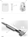
- a sample system in accordance with the invention and as shown in Figure 1 including a stimulus generation unit 101 or controller and a somatosensory stimulation unit 102.
- the controller receives an audio signal as an input and generates a plurality of actuation signals representative of the audio signal. This plurality of actuation signals are delivered to the somatosensory stimulation unit 102. Controller 101 also generates a corresponding binaural modified audio signal for delivery to a subject being treated. Delivery of the modified audio signal is carried out using headphones or audio transducers 103 as shown in Figure 1 . While shown as part of the system in figure 1 , this is as an example only and the system may be supplied without the headphones.
- any other audio delivery mechanism may be used for example loudspeakers located proximal to the patient, bone conduction transducers, cochlear implants, in ear audio transducers such as in-ear headphones or hearing aids, sound-from-ultrasound technology or over-ear audio transducers.
- the headphones shown in Figure 1 are arranged to deliver stereo audio having a -3dB frequency response of 20 Hz to 20 kHz, and a dynamic range of > 90dB.
- the auditory and somatosensory stimulation are delivered substantially simultaneously to a patient. This simultaneous delivery introduces a fixed delay between audio and somatosensory (up to +/- 50ms).
- a random variation in delay between audio and somatosensory stimuli may be introduced to cover a wide range of latencies over the course of a treatment session.
- the somatosensory stimulation unit in a preferred embodiment is an intra oral device (IOD).
- IOD intra oral device
- the IOD of Figure 1 is dimensioned to be located on the tip (dorsal anterior region) of the tongue of the subject undergoing treatment. It will be appreciated however, that the device may also be dimensioned to be located on any part of the subject wherein a relevant nerve for the treatment of the neurological disorder can be stimulated, for example
- the somatosensory stimulation unit is an intra oral device (IOD).
- IOD intra oral device
- the configuration shown in Figure 1 relates to a first embodiment wherein the stimulus generation unit is located remote from the IOD at the control unit 101. In the examples below, this configuration is referred to as MB1. In an alternative configuration, referred to as MB2, the stimulus generation unit may be located local to the IOD 102, for example using a microcontroller or other programmable device to generate the stimuli.
- the IOD or somatosensory stimulation unit includes an array of stimulators 1022 each of which can be independently actuated to apply a somatosensory stimulation to a subject synchronously with the modified audio signal.
- a comparator is required for each stimulator in the array in order to drive each stimulator or electrode. These comparators may be located on the circuit board in the controller 101.
- the microcontroller is configurable to drive the electrodes or stimulators directly, said microcontroller and support components may be located on printed circuit board 1021. This configuration minimises the component count and thus the cost.
- the PCB 1021 and the array 1022 as shown in Figure 2 are encapsulated within a moulded unit 1023.
- the moulded unit is over moulded.
- a moulding process is suitable for an injection moulding process, thus minimising the cost of the IOD.
- a Parylene C coating for example may be applied to the PCB before over moulding to seal it.
- Parylene is a hydrophobic polymer microfilm applied by Chemical Vapour deposition. Parylene dimers are vaporised and converted to a monomer at 690°C. It is then introduced to a vacuum chamber where it forms a polymer coating at room temperature. Appling a Parylene C layer of 12-15 ⁇ m seals the IOD and mitigates the risks associated with saliva ingression to the PCBA, leaching toxins, egressing back out, and being ingested by the subject.
- a peak driving voltage of at least 5V may be required.
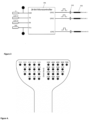
- An exemplary microcontroller arrangement is shown in Figure 3 .
- the microcontroller 301 is a 16 bit microcontroller, however, it may also be an 8 bit or 32 bit microcontroller, an FPGA, custom chip or the like.
- the microcontroller includes a plurality of inputs and a plurality of outputs 302 arranged to drive each individual electrode in the stimulator array. Each line driving the electrodes has a capacitive element 303 thereon to prevent direct currents from flowing through the subject.
- the power supply provided to the voltage input of the IOD is provided by the controller or stimulus generation unit remote from the array.
- the IOD is powered by the controller, no additional regulation circuitry is required within the IOD itself and accordingly, the component cost and requirement for the IOD is reduced.
- a local decoupling capacitance (not shown) may be provided on the MCU supply rail to supply worst cast transients due to electrode drive switching.
- the MCU 301 drives each electrode by way of the series capacitor 303 on the drive line from the GPIO to the electrode. This configuration facilitates a subset of electrodes to be active at any given instance in time, thereby allowing all other electrodes to act as a stimulus current return path.
- the IOD may be detachable from the controller or may be integral thereto.
- a Universal Serial Bus, USB, optionally with custom overmoulding, or other connector may be provided for connecting to the controller. This other connector may prevent connection to non-medical equipment.
- the top surface of the electrode array within the encapsulation 1023 that makes contact with the mucosal membrane is masked so an electrode-membrane interface is unaffected by the coating process. It will be appreciated that the masking material must be bio-compatible. Parylene C as described above is chemically inert and biocompatible.
- a suitable array may comprise two or more arrays. These arrays can be contained in separate devices and for example may be located across the back of the neck, or split between one side of the face (jaw) and the opposing side of the face.
- the somatosensory stimulation unit also comprises a second array comprising at least two stimulators (not shown in the figures). These stimulators are in an arrangement, arranged relative to the array of stimulators and configured to deliver a pseudo stimulus to the subject.
- This pseudo-stimulus includes additional stimulus channels which are configurable to provide a sensation of an effect to the patient but which are not part of the therapeutic stimulus.
- the pseudo stimulus can be activated to improve or increase the sensation perceived by the patient. Further, this facility assists in clinical trials where a "fake" treatment is required.
- This pseudo stimulus may be implemented with a single stimulus or two stimuli channels, however any number of stimuli channels may be facilitated. In a configuration the pseudo stimulus is asynchronous to any auditory stimulus. Further it may have a low duty cycle relative to the therapeutic stimulus. Furthermore, the pseudo stimulus may be blocking in nature.
- said pseudo stimulus can be elicited through the IOD 102 without any additional stimulators. This is achieved by multiplexing in time the pseudo stimulus with the treatment stimulus. In this scenario a mark:space ratio of at most 10% would be required to impart significant stimulus percept to the subject, while delivering the treatment stimulus for at least 90% of the treatment session duration.
- the main constraints in the design of a suitable audio signal for auditory stimulation of a subject are as laid out in table 1 below.
- MB1 a first example
- two audio tracks were chosen, namely "Forest Raindrops” by Relax With Nature as the foreground, broadband sound and Erik Satie, "Gnossiennes” and “Gymnopodies” performed by Reinbert de Leeuw.
- the mixing was performed as follows: Both audio tracks are extracted to 16bit 44.1kHz wav files and normalised to -0.1dB. Waves L3 compressor may be used on both, with a threshold setting of -12dB, no dither, other settings default.
- the amplitude of the Satie was reduced by 18dB, extra reverb applied (to enhance the illusion of the music coming from the distance) and was then mixed with the Forest Raindrops with an overall gain of -1dB to avoid saturation during the mixing.
- the resulting mix was truncated to 30 minutes, and a short lead in crescendo and lead out decrescendo, before being exported as a 16bit 44.1kHz .wav file.
- MB2 In an alternative example (MB2) the two sound tracks chosen included "Forest Raindrops" by Relax With Nature as the foreground, broadband sound and Erik Satie, "Gnossiennes” and “Gymnopodies” performed by Therese Fahy (the applicant commissioned Therese Fahy to perform these works, which were recorded in RTE Radio Studio 1 on the 7 th and 8 th January 2015, on a Steinway Grand piano).
- the mixing was performed as follows: Both audio tracks were extracted to 16bit 44.1kHz wav files and normalised to -1dB (to pre-compensate for the overall gain reduction of -1dB applied in the first configuration's audio mixing).
- Audio stimulation design constraint Rationale The audio stimulus should be spectrally broad • To stimulate as many of the afflicted auditory pathways as possible The audio stimulus should contain a high density of fine-grained temporal sounds • So that the auditory processing structures can make frequent correlations between the sound and the electro-tactile stimulation (ETS). The fine-grained sounds within the audio stimulus should be randomly spread in the temporal and spectral domains. • This will ensure that the spatial and temporal characteristics of the somatosensory stimulation (derived from the audio) will be also random, thereby facilitating a neuromodulation-only mode of action.
- ETS electro-tactile stimulation
- the audio stimulus should promote a sense of relaxation in patients • To maximise patient's comfort • To reduce patient's stress levels • To maximise patient's tolerance of the treatment The audio stimulus should eliminate repetition within the period of a standard treatment session (30 minutes) • To minimize boredom, thereby increasing the patient's tolerance of the treatment • To increase patient's attentiveness during the treatment The audio stimulus should have limited dynamic range, limited close to what the dynamic range of ETS perception on the tongue is. • So that the mapping to the ETS pattern results in a relatively consistent stimulus intensity. • To maximise the periods during which the affected auditory structures are stimulated, especially in patients that have significant hearing loss in certain bands. • There is no basis to believe that wide dynamic range would have any additional benefit to the patient.
- the audio stimulus should contain a musical sound track mixed with the broad band foreground, such that it sounds to the patient that the source of the music is originating from a spatial location that is far away.
- the broadband noise may include a mixture of speech.
- the audio stimulus should be filtered to compensate for their hearing loss, or band-boost filtered at a frequency that is close to the patient's hearing profile roll-off frequency, or to their tinnitus match frequency if their hearing is normal • To boost the stimulus, and resulting neuromodulation in the region of the patient's hearing deficit, or at a frequency that most closely matches their tinnitus dominant frequency.
- the audio stimulus should be stereo • To maximise patient's comfort by simulating a sense of space (mono audio through headphones can make the sound appear as though it emanates from a single, central point) • To facilitate adequate auditory stimulation for patients that have an asymmetrical hearing loss or tinnitus loudness.
- the resulting mixes were truncated to 31.5 minutes, and a short lead in crescendo and lead out decrescendo, before being exported as a 16bit 44.1kHz .wav files.
- the files above are examples only and it will be appreciated that other combinations of audio stimuli could also be implemented as long as they meet the design criteria set out above.
- the system as described above may also have the facility to select one of a multiple of files. These files may be selectable by the subject.
- an additional audio stimulus filtering is implemented.
- Most tinnitus patients suffer from a hearing loss at one or more frequencies, with the tinnitus most commonly associated with the side ipsilateral to their hearing loss.
- a boost filter is implemented to facilitate compensation for the relevant frequency bands.
- constraints of the filtering include:
- a set of filters is configurable.
- the filters are configurable as follows (this example represents the MB2 configuration) in Table 2.
- the audio stimulus filtering in the MB1 configuration is the same, except the 10kHz and 12.5kHz bands were not utilised, because at the time only a standard audiometer was used (audiological assessments conducted up to and including 8kHz).
- the filters are examples only, and in this case designed for ease of implementation and low processing power to implement.
- These filters spectrally modify the audio input to compensate for a deficit in the hearing profile. For example applying a band boost filter with centre frequency correlated to fall-off frequency as determined by the patient's audiogram will compensate for the deficit.
- a band boost filter may be calibrated in accordance with the steepest roll off of the audiogram of the patient with the half power bandwidth of the band boost filter between 0.5 and 1.5 octaves normalised to the centre frequency, and with a boost magnitude of at least 12dB. Table 2.
- the filter may be a boost filter calibrated based on the inverse of the audiogram of the subject in the ipsilateral ear and the filter may be configured to compensate for deficits of at least 30dB and operable in the range 500 Hz to 16kHz. It will be appreciated that other filter implementations can be implemented that are better at compensating for the subject's hearing loss.
- transducers including hearing aids, proximal loudspeakers, and cochlear implants.
- a bone conduction transducer may be an acceptable alternative.
- the inner ear mechanisms including the cochlear function
- wireless headphones are unsuitable where the patient suffers from electromagnetic hypersensitivity (EHS), proximal loudspeakers or wired headphones may be used.
- EHS electromagnetic hypersensitivity
- EHS electromagnetic hypersensitivity
- in-ear sound-isolating earphones such as Shure SE215 or over ear noise cancelling headphones may be used.
- the background noise levels may need to be 20dBA or less. Many patients live in environments that have consistent noise levels well above this level.
- cochlear implants may provide an alternative.
- the hearing loss is sensorineural and profound, such as in cases of congenital deafness, acoustic or vibration transducers may provide no stimulus to the auditory pathways.
- cochlear implants may provide the only means of stimulation the auditory branch of the VIII nerve.
- proximal loudspeakers may be used.
- ETS electro-tactile stimulation
- Mechanical stimulation can be easily set to a level that is neither too high, nor too low, as the qualitative level of perception the patient reports will be commensurate with the degree of nerve impulses passing through the sub-cortical structures.
- the somatosensory stimulation is applied to the anterio-dorsal surface of the tongue.
- the tongue is a mucosal surface that is coated with a replenishing electrolyte (saliva) that enhances transcutaneous electrical stimulation.
- the anterio-dorsal surface of the tongue possesses one of the highest somatic nerve densities in the human body and as a result has a disproportionately large representation in the somatosensory homunculus.
- vagus nerve stimulation for the treatment of Tinnitus,( De Ridder, Dirk, et al.
- the lingual branch of the trigeminal nerve innervates the anterior surface of the tongue. Studies have demonstrated that there are important anatomical and functional links between the trigeminal nerve and central auditory structures, such as the cochlear nuclei. However while described herein with reference to the anterio-dorsal surface of the tongue, other sites of stimulation could be used, in particular sites that allow transcutaneous stimulation of various branches of the trigeminal nerve, Vagus nerve, or C1/C2 nerves.
- One of the key parameters with respect to implementing bi-modal neuromodulation systems is that of the signal bandwidth represented.
- the information rate of the auditory stimulus can be set very high, since the human hearing apparatus is capable of decoding very complex sounds.
- Perceptual encoding of complex auditory signals can only achieve high fidelity with 64kbits/s or higher for 16bit dynamic range, 12kHz bandwidth (24.050kHz sample rate and covering a 8 octave range from about 50Hz to 12kHz), even when utilising the most advanced perceptual encoding algorithms (e.g. AAC, Vorbis/OGG).
- the perceptual encoding dynamic range for amplitude via electro-stimulation on the tongue is approximately 9 levels including zero (which can be represented digitally with 4 bits of information), and the frequency range of operation limited to between 500Hz and 8kHz (a range that spans 4 octaves).
- mapping between the audio and somatosensory stimulus are possible, some of which are described in the table 3 and as shown in figures 17 and 18 .
- the MB1 and MB2 use spectral transformations with high temporal and low frequency resolution, because of the limited frequency resolution required (critical bands according to the Bark scale, see below) and the resulting efficiency of implementation.
- the spectral information can be mapped to somatosensory information in several ways, including:
- the MB1 and MB2 use a tonotopical mapping, akin to that which occurs in the cochlea (where differing frequencies cause a tonotopic spread of hair cell stimulation).
- the auditory stimulus is analysed as a discrete number of frequency bins, and each frequency bin is assigned to one of a multitude of electrodes in the array, covering the range of frequencies that are typically affected in age related and noise induced hearing loss (as research shows that in most cases subjective tonal tinnitus occurs in a frequency band close to the dip frequency (noise induced hearing loss) or roll-off frequency (for age-related or ototoxicity related sensorineural hearing loss) of the patient.
- This mapping is amenable to a single electrode (monaural) or dual electrode (split array) arrangement.
- Spectral Low High Mapping spectral information directly to somatosensory events with significant blurring of the temporal information Analysing the spectral content of the auditory stimulus over temporally long periods, and triggering somatosensory events based on threshold detection of energy at particular frequencies.
- Spectral High Low Mapping spectral information directly to somatosensory events while maintaining temporal resolution but limited frequency resolution Dividing the auditory stimulus into short analysis frames, and estimating the spectral content within each frame and triggering somatosensory events based on threshold detection of energy at particular frequencies within each analysis frame.
- Spectral High High Mapping spectral information directly to somatosensory events, while maintaining temporal resolution and frequency resolution Dividing the auditory stimulus into variable length overlapping analysis frames, and estimating the spectral content within each frame (similar to performing a wavelet transform) and triggering somatosensory events based on threshold detection of energy at particular frequencies within each analysis frame. This mapping is covered in an alternative configuration.
- Electrodes can be used to represent twice as many frequency bands • May be more effective at promoting neuroplastic changes in sub-cortical structures, because the auditory stimulus for each side is matched to the ipsilateral somatosensory stimulus • The issue of centring the array is not as critical as in the case for the split array because the in the latter case it is required that the somatosensory stimulation operates on the ipsilateral side only Disadvantage s: • May not be as effective at promoting neuroplasticity in sub-cortical structures, because there will be a mismatch between the auditory stimulus and the somatosensory stimulus on the ipsilateral side. • Only half as many frequency bands can be presented with a given number of electrodes • Centring the array, such that stimuli affect the ipsilateral side only, poses design challenges in certain embodiments (such as tongue stimulation)
- the spectral encoding is such that each electrode maps to a particular frequency bin.
- the choice of an appropriate division and range that these frequency bins cover is of critical importance to the design of the system.
- Spectral encoding using linear scale is not optimal because no part of the human auditory system, either in pitch or amplitude, operates on a linear scale (our perception of both pitch and loudness are both on logarithmic scales).
- a linear scale is very inefficient at representing pitches that extend across such a significant range of our hearing, and as a result would result in highly disproportionate weighting to the higher frequencies in our hearing range than the lower frequencies.
- a logarithmic (base2) scale is more suitable than a linear scale, especially where the audio stimulus comprises of harmonic music.
- base2 scale does not match the physiology of the cochlea very well (as per the Place theory), especially at higher frequencies (where perceptual scales are more appropriate).
- chords or harmonics in any musical components would align with patterns of electrodes, whereas with the perceptual scale (such as Mel or Bark scale) only dissonant chords would align with patterns of electrodes.
- Bark Scale (psychoacoustic critical bands)
- Bark scale a scale where pitches are perceptually equidistant from each other
- Zwicker, Eberhard “Subdivision of the audible frequency range into critical bands (Frequenz phenomenon).” The Journal of the Acoustical Society of America33 (2) (1961): 248 .).
- the Mel scale it is based on psychoacoustic experiments on humans, where the resulting steps in the scale are judged equidistant in pitch.
- the critical band is the band of audio frequencies within which a second tone will interfere with the perception of the first tone by auditory masking).
- the MB1 and MB2 embodiments base frequency binning on the Bark scale critical bands when there are limited electrodes available (as in the split array design), and a log (base2) scale when there is less of a limitation on the number of electrodes (as in the single array design).
- the lower frequency was chosen as the 1 percentile corner frequency of the population that suffer from sensorineural hearing loss (Congenital, NIHL, presbycusis, ototoxic induced hearing loss etc.), which is approximately 500Hz (Congenital cytomegalovirus (CMV) infection & hearing deficit (Fowler, Boppana) 2005, Fowler ; CMV A Major Cause of Hearing Loss in Children (2008), http://www.cdc.gov/nchs/data/series/sr_11/sr11_011acc.pdf (page 7 , fig 5 )).
- CMV Congenital cytomegalovirus
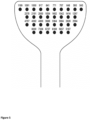
- a minimum of 16 x 2 electrodes is required (32 electrodes).
- the following frequency bins are required (as per the bark scale) [Hz]: 570 700 840 1000 1170 1370 1600 1850 2150 2500 2900 3400 4000 4800 5800 7000
- An electrode array of size 32 electrodes was chosen for the MB1 design to be able to accommodate the split-array design.
- a deadband may be included between the right side and the left side stimulators. This is illustrated in Figure 4 .
- the dorsal anterior region of the tongue where spatial resolution and sensitivity are at their highest, can easily accommodate the 32 electrodes on a grid spacing of 2mm.
- the frequency bin spacing is decreased such that there are 8 bands per octave, thereby dividing the required frequency range into 32 logarithmically evenly-spaced bands across the full frequency range of interest (500Hz to 8kHz).
- Frequency bins are separable equidistant on a log (base 2) scale to maintain a consonant harmonic relationship between the frequency bins.
- Somatosensory stimulation may be a trans-mucosal or trans-cutaneous electro-tactile stimulus (ETS).
- ETS trans-mucosal or trans-cutaneous electro-tactile stimulus
- MOA mechanism of action
- the act of depolarizing somatosensory nerve fibres may be sufficient for the device to be effective, since the depolarising of the nerve fibres should result in neural spikes reaching one or more of the subcortical structures in the brain.
- depolarising somatosensory nerve fibres is not always sufficient to illicit a percept and therefore it cannot be assumed that a percept is essential for the stimulation to be effective.
- in-vivo testing was performed using the MB1 configuration prior to use in a 2012 clinical investigation, and data was gathered electronically during them. Further in-vivo tests were also performed on the MB2 configuration as part of the design and clinical validation processes.
- Global amplitude control is essential in order to accommodate the natural variation in physiological, physical and genetic factors affecting the sensitivity, conductivity and perceptual characteristics of the patient population including
- the amplitude may be under direct control of the patient to they adjust the intensity to a comfortable level, for example by adjusting the controls on the Control Device, 101.
- the system described herein also includes stimulation amplitude control so that the intensity of stimulation can be adjusted per patient.
- stimulation amplitude control so that the intensity of stimulation can be adjusted per patient.
- intensity control pulse width/pulse amplitude and number of consecutive pulses
- the corresponding JND within this range was found to be 12.5% of the dynamic range on average, such that 8 different amplitude levels could be discriminated between the threshold of perception and the threshold of discomfort ( ⁇ 2.4dB per step), but as low as 1.5dB per step for certain parts of the perceptual range.
- the range of perception threshold varied by 10dB across all 8 subjects in the experiments. Taking the lower step size of 1.5dB, and dividing it into the total required range (17.39 dB + 10dB) results in a minimum of 18 steps required.
- the pulses on the MB1 were constant width (17.7us), and the voltage varied according to the amplitude setting (under the control of the patient), i.e. basing the stimulus drive circuit on voltage-mode control.
- the voltage levels utilised, along with the resulting volt-second product (potential to depolarise) are detailed in the table below.
- This change to the somatosensory electrode drive circuit is due to the necessity to migrate the electrode drive circuit from the Control Device to the Intra-Oral Device.
- This necessity stems from fact that the passive IOD in the MB1 required a 32-core cable from it to the Control Device. The cost of this cable and associated connectors is very high, and the reliability and flexibility of the arrangement is less than optimal. Moving the electronic drive circuit from the Control Device to the IOD in the MB2 design results in a lower cost and higher reliability product.
- the MB2 is based on a low cost microcontroller unit (MCU), with its outputs capacitive coupled directly to the electrodes.
- MCU microcontroller unit
- This electronic drive circuit change requires that the drive voltage level in the MB2 be limited to between 4.35V (so a low cost boost converter can be used from a 4.2V Lithium Polymer battery), and 5.85V (just below the absolute maximum supply voltage limit of the MCU), whereas in the MB1 it is adjustable from 3V to 11V. This requires that the range of pulse widths in the MB2 design be increased to compensate for the change in range of the pulse voltage.
- Pulse widths longer than 100us will result in the 100nF series capacitor being more than 20% discharged by the end of the pulse, and so 100us is a realistic upper limit for the pulse width. Also, longer pulses will increase the risk of irritation and sensitisation to the mucosal surface due to electrolysis by-products under the electrodes, because the longer the first phase of the pulse the less the by-products of the electrolysis reaction will be reversed by the 2nd phase (opposite polarity phase) of the pulse.
- a 100us pulse should deliver significantly more energy (neglecting the effect of the DC blocking capacitors) than the 17.6us pulses used in the MB1 configuration.
- the requirement is to set the lowest (non-zero) pulse width to achieve the same charge injection as the lowest amplitude setting on the MB1.
- the pulse width is under the direct control of the patient. For example, it may be adjusted by pressing stimulus amplitude control buttons e.g. (UP/DOWN button pair) on the Control Device 101.
- stimulus amplitude control buttons e.g. (UP/DOWN button pair) on the Control Device 101.
- Dynamic amplitude control of the somatosensory stimulation is useable as a means of encoding the relative amplitude of the audio stimulus from which the somatosensory stimulus is derivable. It will be appreciated that this facilitates greatly increasing the information rate of the somatosensory stimulus, so that it can more closely match the information rate of the audio stimulus from which it is derived.
- the increase in information rate that can be achieved is essentially limited by the somatosensory perceptual dynamic range of the human tongue.
- JND Just-Noticeable Difference
- Pulse Count Control High Dynamically adjusting the pulse count was deemed the most appropriate method of dynamic amplitude control for the following reasons: • The dynamic range of 17.39dB in 8 discrete steps is feasible, given the frame rate and number of electrodes (see below) • It mitigates the need for expensive, space hungry and power hungry electronics to drive the electrodes • It retains the ability to adjust the pulse width as a means of global stimulation amplitude (which requires at least 17 discrete steps, see above).
- Pulse count control is achievable in practice by simply varying the number of electrical pulses on any given electrode, in any given frame. This corresponds to a discrete number, or count, of pulses in a burst, where the burst is shorter than the analysis frame length. As long as the duration of the frame is less than or equal to period of sensory integration (period of tactile simultaneity), the pulses are wide enough to depolarise the nerve fibres, and the pulses are spaced far enough apart (i.e. that the neurons can repolarise in time before the next pulse), the perceived amplitude of the stimulus is proportional to the number of pulses up to and including 6 or 7 pulses (] Kaczmarek, Kurt, John G. Webster, and Robert G. Radwin. "Maximal dynamic range electrotactile stimulation waveforms.” Biomedical Engineering, IEEE Transactions on 39.7 (1992): 701-715 ).
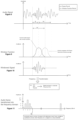
- Figures 8 to 14 serve to illustrate the transformation between audio and somatosensory stimulation, but is generalised in terms of the number of frequency bins (n) and the number of quantised amplitude levels (q).
- FIGS. 1 and MB2 illustrate how one of the binaural channels is transformed for use in a split-array stimulator topology.
- the left and right audio channels are mixed prior to the transformation (with the audio kept as stereo for delivery to the patient via the headphones).
- the pulse pattern is illustrated for one electrode only (electrode #3 in this case, which corresponds to frequency bin #3).
- the number of frequency bins to be represented via somatosensory stimulation 32 The frame length should be long enough to accommodate the product of • The number of frequency bins AND • The number of pulses per frame (for dynamic range control) at the maximum pulse width, such that there are no temporally overlapping pulses.
- the frame length should be long enough such that there are at least two periods at this frequency (4 periods including the window function), i.e.
- the maximum pulse width required to ensure strong stimulus percept 17.7 us (MB1)
- the pulse slots must be long enough to accommodate pulses of these widths 78 us (MB2)
- the frame length should be long enough to accommodate the product of • The number of frequency bins AND • The number of pulses per frame (for dynamic range control) at the maximum pulse width, such that there are no temporally overlapping pulses.
- the electrode topology is configured in accordance with a number of considerations.
- the MB2 and MB1 are designed such that the same electrodes also act as the return path electrodes.
- a dedicated return electrode is not necessitated, but rather to configure all electrodes apart from the active electrode at a particular point in time to act as joint return electrodes.
- the ideal stimulation paradigm is to have no overlapping pulses, i.e. that only one electrode is ever active at a particular point in time.
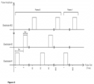
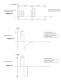
- the somatosensory pulses should occur at the same timing resolution as the audio samples, i.e. at a resolution of 1/44100s (22.6uS). To accommodate this, the time axis is divided up into "Pulse Slots" of period t ps .
- the time pattern of the tactile pulses are generated. There are a total of 256 pulse slots per frame. Each electrode is assigned a subset of the available time slots as diagrammed in Figure 6 . This figure outlines the pattern of pulse slots for a single frame (frame 0), and a follow on frame (frame 1).
- the total number of slots that an electrode is set active in any given frame is determined by the amplitude of that frequency bin in the frame. For example, if the amplitude level is 2, then the first two slots for the electrode are set active and the remaining are kept de-activated. In the example shown in Figure 6 , there is 8 pulses for each of electrodes #1, #2 and #32 in Frame 0.
- MB1 and MB2 configurations use pseudo-biphasic, anodic (positive leading) pulses, as diagrammed in "Pulse Detail B" of figure 14 .
- Pseudo-biphasic pulses are generated using a rectangular wave voltage source, with a series capacitor to the active electrode. Because the net charge across the capacitor always sums to zero (an ideal capacitor has infinite impedance to direct current), the pulse is effectively biphasic. This results in minimal electrolysis products generated at the electrode / mucosal surface interfaces, thereby maintaining the integrity of the electrodes and minimising the risk of sensitisation or iteration to the patient.
- Stimulation Source Type Advantages Disadvantages Voltage sources • Low cost and complexity to implement • More difficult to control the injected charge, especially if the contact area and contact electrolytes have a tendency to vary over time • Less exposure to hazardous energy density in the event that the electrodes become partially disconnected Current sources • High degree of control of the delivered charge • Potential for exposure to hazardous energy density in the event that the electrodes become partially disconnected, particularly for transcutaneous stimulation on dry skin using electrodes with large surface area. • High cost and complexity to implement
- the stimulation is assumed to be voltage-mode control, however, it will be appreciated that current mode control can also be used. Based on in-vivo tests, at 50us pulse width, the voltage on a 47nF series blocking capacitor dropped from increased from 0V to 1.35V on average across all users. The required current is therefore
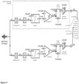
- a potential disadvantage with the audio to somatosensory mapping described above in relation to the configurations proposed for the MB2 and MB1 configuration is that there may be significant temporal smearing of auditory events when transformed into the somatosensory signals, particularly at higher frequencies, because:
- the schematic shows just two of the n frequency channels of the transformation, and for one side of the split-array configuration only. In this regard, only the left audio channel is shown.
- the auditory stimulus component (including the mechanisms relating to the spectral modifications and amplitude adjustment) is not shown in this schematic, as it is the same for the MB1 and MB2 configurations detailed above.
- the timing diagram indicates the typical timing for one of the n channels.
- Two analysis frames are shown as an example, the first frame indicates a scenario whereby there is sufficient energy in the relevant frequency band to cause a somatosensory pulse to be generated, whereas in the second frame there is insufficient energy and hence a somatosensory pulse is not generated.
- the band pass filters are designed such that they have centre frequencies and bandwidths as per the Bark scale critical bandwidths.
- a gammatone filter bank would be suitable in this regard, as the filter response closely matches the response of the basilar membrane in the cochlea.
- Timing signals, IntReset[x], PulseSet[x] and PulseReset[x] are arranged such that
- the global delay between the auditory and somatosensory stimuli can be configured by setting a delay on the audio signal to the patient (if it is required that the somatosensory stimulus leads the auditory stimulus), or by including a delay line in the somatosensory signal lines (Q[x]) if it is required that the auditory stimulus leads the somatosensory stimulus.
- the transformation can be implemented in either the analog or the digital domains, since there are no elements of the system that requires a digital signal processor. However, it will be appreciated that in order to reduce the associated electronics cost, it would be preferable to implement the transformation in the digital domain.
- this transformation is performed either offline, as would be the case in the MB2 configuration, or online.
- the advantage of the former is that the implementation is lower power, and will extend the battery life in portable embodiments of the system.
- the MB2 configuration of the system can be programmed to implement this transformation by software changes alone.
- the CPU transforms the audio into the required somatosensory stimulus, and displays this stimulus on the somatosensory stimulus arrays 708 in synchronisation with the audio, 709, which is delivered through a set of headphones (though bone conduction transducer, loudspeakers, hearing aids or cochlear implants or other audio transducers can also be used as described above).
- Key parameters relating to the delivery of the stimulus to the patient are recorded to file and stored on the memory, such as the card 706. These parameters include, but are not limited to, the following:
- a patient interface 703 is also provided to allow the patient to adjust the stimulus levels and the start and end of the treatment sessions. Events such as low power or low battery may also be reported to the patient. Again this may be any visual or haptic display and may include visual display units, mobile computing devices and applications run thereon or the like.
- MML Minimum Masking Level
- TLM Tinnitus Loudness Matching
- TMI Tinnitus Handicap Inventory
- the screening assessments were carried out during periods without any stimulation from the device. There are several factors outside of the treatment of the condition that can affect the perceived benefit from any treatment of tinnitus. Hesser et al (The effect of waiting: A meta-analysis of wait-list control groups in trials for tinnitus distress. J Psychosom Res. 2011 Apr;70(4):378-84 ) reviewed the response rates of participants on a waitlist for tinnitus treatments and found that participant's distress can reduce over short wait periods.
- MML Minimum Masking Level
- TLM Tinnitus Loudness Matching
- TMI Tinnitus Handicap Inventory
- participant were provided with the neuromodulation device to take home for the remainder of the study and asked to use it for between 30 and 60 minutes every day for the next 10 weeks. Participants were shown how to use the device and told to set the audio and tongue stimulation to the most comfortable levels for them. Participants were asked to return to the clinic every two weeks in order to repeat the assessments carried out in the screening period. Where it was not possible for participants to return to the clinic, they completed the paper version of the THI remotely and sent the copy to the investigator site. Participants were advised to terminate device use and to contact the investigator if they experienced any side-effects or adverse events. They were also instructed to contact a member of the research team regarding any device malfunction.
- Participant compliance with treatment administration was determined technologically using the data logging function on the device. The following events, along with their date and time, were recorded in non-volatile memory:
- the protocol required participants to use the device for between 30 and 60 minutes a day, 7 days a week. Compliance in this context refers to the number of days over the course of the treatment where the session duration, i.e. how long the device was used continuously, was at least 30 minutes. In clinical studies of pharmaceuticals, participants are considered compliant if their adherence is greater than 80%. The exact durational properties of this treatment are still under investigation and so a somewhat more generous cut off for compliance was employed, i.e. 66%; the cohort was divided into those that are considered 'compliant' and those that are considered 'non-compliant' according to this threshold.
- the data set for this study consisted of THI, TLM and MML data from 44 participants over 10 weeks of treatment. Data on compliance to study protocol as well as audio and somatosensory stimulation settings used by the participants over the ten weeks was also collected. Participant data was included in the analysis if tinnitus symptom scores were available for baseline(V2) and at least the penultimate visit, and if they had access to the device for at least 8 weeks, i.e. did not return the device early. The analysis in this paper investigates whether any statistical improvement in the three assessments of tinnitus symptoms was observed after 10 weeks of treatment with the device.
- THI scores are not normally distributed, so the Wilcoxon signed rank test was employed to test for statistical significance between baseline(V2) and final visit.
- TLM and MML datasets were found to be normally distributed and a paired t-test was employed to test for statistically significant differences between baseline(V2) and V7. In addition to analysis of statistical difference, the proportion of participants achieving clinically significant differences was assessed.
- Jastraboff et al Jastreboff PJ, Hazell JW, Graham RL. Neurophysiological model of tinnitus: dependence of the minimal masking level on treatment outcome. Hear Res. 1994 Nov;80(2):216-32 ) reported that a decrease in 5.3 dB on the MML scale significantly correlated to patients reporting improvements in their tinnitus.
- the log files provided information on device usage as well as stimulus levels over the course of treatment for both auditory and somatosensory stimuli. Secondary analysis examined patterns of auditory and somatosensory stimulus to investigate any insights into participant's usage of the device.
- the impact of auditory and somatosensory multi-modal stimulation, on outcome measures of chronic tinnitus was determined by measuring the change in the THI, MML and TLM scores over time.
- a cohort of 54 participants was recruited as part of this trial, each participant was required to complete 3 intervention free screening assessments and 5 subsequent assessments while using the device.
- the symptom scores assessed without intervention at V0, V1 and V2 are employed to better understand variability and improvements in symptoms that may be attributed to non-interventional influences.
- the average intra-subject coefficient of variance, COV, for the THI, TLM and MML scores over the 3 screening visits, i.e. non interventional monitoring, are 21%, 16% and 13% respectively.
- Baseline values for analysis were taken from the 3 rd screening visit, i.e. V2, average and standard variation can be seen in Table 13. Changes in the average THI, TLM and MML scores, for the full cohort over time, are presented in Fig. 15 .
- Table 11 demographic profile of participants.
- Table 12 presents the number of participants who achieved clinically significant improvements, as discussed in the analysis section, per symptom, for those that are considered compliant and non-compliant. The highest proportion of improvers are seen on the MML scale, 73% of the 30 participants demonstrating a clinically significant improvement in MML.
- Table 12 presents the number of improvers/non-improvers for each tinnitus symptom in each compliance class; Improvers: THI ⁇ Improvers: TLM ⁇ Improvers: MML Full Cohort (44) 20 (45%) 21 (48%) 28 (64%) Compliant (30) 17 (57%) 15 (50%) 22 (73%) Non-Compliant (14) 3 (21%) 6 (43%) 6 (43%) ⁇ Improvers achieve a minimum drop of 7 points on THI scale ⁇ Improvers achieve a minimum drop of 5.3 dB on TLM scale Improvers achieve a minimum drop of 5.3 dB on MML scale
- Table 13 presents the average THI, TLM and MML scores for baseline(V2) and V7 for the full cohort and when the cohort is divided into two classes; compliant and non-compliant.
- Table 13 Average tinnitus symptom values for baseline and final visit, *p ⁇ 0.05, **p ⁇ 0.01, ***p ⁇ 0.001 THI (pts) TLM (dB) MML (dB) V2 (SD) V7 (SD) V2 (SD) V7 (SD) V2 (SD) V7 (SD) Full Cohort (44) 33.7 (24) 25.1 (20)*** 42.9 (15) 37.5 (17) 47.3 (15) 39.2 (17)*** Compliant (30) 35.8 (25) 24.1 (20)*** 44.8 (16) 37.3 (16)*** 49.0 (15) 39.2 (18)*** Non-compliant (14) 29.3 (24) 27.4 (23) 38.6 (14) 37.7 (19) 43.8 (17) 39.1 (18)
- the above-described embodiments of the present technology can be implemented in any of numerous ways.
- the embodiments may be implemented using hardware, software or a combination thereof.
- the software code can be executed on any suitable processor or collection of processors, whether provided in a single computer or distributed among multiple computers.
- any component or collection of components that perform the functions described above can be genetically considered as one or more controllers that control the above-discussed functions.
- the one or more controllers can be implemented in numerous ways, such as with dedicated hardware, or with general purpose hardware (e.g., one or more processors) that is programmed using microcode or software to perform the functions recited above.
- one implementation of the embodiments of the present technology comprises at least one computer-readable storage medium (e.g., a computer memory, a floppy disk, a compact disk, a tape, a flash drive, etc.) encoded with a computer program (i.e., a plurality of instructions), which, when executed on a processor, performs the above-discussed functions of the embodiments of the present technology.
- the computer-readable storage medium can be transportable such that the program stored thereon can be loaded onto any computer resource to implement the aspects of the present technology discussed herein.
- the reference to a computer program which, when executed, performs the above-discussed functions is not limited to an application program running on a host computer. Rather, the term computer program is used herein in a generic sense to reference any type of computer code (e.g., software or microcode) that can be employed to program a processor to implement the above- discussed aspects of the technology.
Landscapes
- Health & Medical Sciences (AREA)
- Life Sciences & Earth Sciences (AREA)
- Engineering & Computer Science (AREA)
- General Health & Medical Sciences (AREA)
- Biomedical Technology (AREA)
- Animal Behavior & Ethology (AREA)
- Veterinary Medicine (AREA)
- Public Health (AREA)
- Physics & Mathematics (AREA)
- Heart & Thoracic Surgery (AREA)
- Radiology & Medical Imaging (AREA)
- Nuclear Medicine, Radiotherapy & Molecular Imaging (AREA)
- Acoustics & Sound (AREA)
- Biophysics (AREA)
- Neurosurgery (AREA)
- Neurology (AREA)
- Audiology, Speech & Language Pathology (AREA)
- Otolaryngology (AREA)
- Anesthesiology (AREA)
- Pathology (AREA)
- Surgery (AREA)
- Molecular Biology (AREA)
- Medical Informatics (AREA)
- Psychology (AREA)
- Signal Processing (AREA)
- Physiology (AREA)
- Cardiology (AREA)
- Multimedia (AREA)
- Pain & Pain Management (AREA)
- Hematology (AREA)
- Vascular Medicine (AREA)
- Electrotherapy Devices (AREA)
Claims (14)
- Eine Vorrichtung zur Verwendung bei der Behandlung einer neurologischen Störung des auditorischen Systems, die eine Stimuluserzeugungseinheit (101) und eine somatosensorische Stimulationseinheit (102) aufweist;
wobei die Stimulus-Erzeugungseinheit, mit einem Audioeingang, so betrieben werden kann, dass sie:ein Audiosignal empfängt und analysiert, wobei das Audiosignal eine erste Komponente aufweist, die eine Breitbandkomponente oder Weißes-Rauschen-Komponente aufweist, und eine zweite Komponente, die eine Vielzahl komplexer Tonbursts aufweist, undeine Vielzahl von Betätigungssignalen erzeugt, die für mindestens eine der ersten oder zweiten Komponente des Audiosignals repräsentativ sind, und ferner das Audiosignal spektral modifiziert, um ein binaurales modifiziertes Audiosignal zur Abgabe an ein Subjekt zu erzeugen; undwobei die somatosensorische Stimulationseinheit Folgendes aufweist:ein Array bzw. eine Anordnung von Stimulatoren (1022), von denen jeder unabhängig betätigt werden kann, um eine somatosensorische Stimulation auf das Subjekt mit dem modifizierten Audiosignal anzuwenden, und einen Eingang zum Empfangen der Vielzahl von Betätigungssignalen von der Stimuluserzeugungseinheit und zum Leiten einzelner Betätigungssignale in einem vorbestimmten Muster zu einzelnen Stimulatoren in der Anordnung,wobei die Stimuluserzeugungseinheit (101) ferner so konfiguriert ist, dass sie eine Verzögerung zwischen der Vielzahl von Betätigungssignalen, die das Audiosignal darstellen, und dem binauralen modifizierten Audiosignal einführt, wobei die Verzögerung eine zufällige Verzögerung zwischen dem modifizierten Audiosignal und der Vielzahl von Betätigungssignalen ist, wobei die zufällige Verzögerung eine rechteckige Wahrscheinlichkeitsdichtefunktion mit Grenzen bis zu +/- 50ms aufweist, oder wobei sie eine Gaußsche Wahrscheinlichkeitsdichtefunktion mit einer Standardabweichung von bis zu 20 ms aufweist, und wobei die Stimuluserzeugungseinheit ferner einen Verstärkungsfilter aufweist, der so angepasst ist, dass er in Übereinstimmung mit einem Audiogramm des Subjekts kalibriert wird, und wobei die Stimuluserzeugungseinheit betreibbar ist, um das Audiosignal spektral zu modifizieren, indem das Audiosignal durch den Bandverstärkungsfilter geleitet wird, um das modifizierte Audiosignal zu erzeugen. - Die Vorrichtung nach Anspruch 1, wobei die Stimuluserzeugungseinheit (101) betreibbar ist, um die Vielzahl von Betätigungssignalen über eine vorbestimmte Zeitspanne zu planen, wobei die Anzahl der Vielzahl von Betätigungssignalen, die über die vorbestimmte Zeitspanne geplant sind, proportional zu einer Amplitude des binauralen modifizierten Audiosignals innerhalb einer Vielzahl von kritischen Bandfrequenzen und innerhalb der vorbestimmten Zeitspanne ist, und optional wobei die vorbestimmte Zeitspanne 23,2 ms beträgt oder wobei die vorbestimmte Zeitspanne so eingestellt ist, dass die Vielzahl von Betätigungssignalen mit einer Zeitspanne von mindestens einer somatosensorischen Nervenfaserrefraktärzeitspanne zwischen jedem der Betätigungssignale auftritt.
- Die Vorrichtung nach einem der vorhergehenden Ansprüche, wobei die Stimuluserzeugungseinheit (101) eine Amplitudensteuerung zum Steuern einer Amplitude des modifizierten Audiosignals und einer Amplitude der somatosensorischen Stimulation aufweist.
- Die Vorrichtung nach Anspruch 3, wobei die Amplitudensteuerung ferner so betrieben werden kann, dass sie die Amplitude des modifizierten Audiosignals für ein Intervall während einer Behandlungssitzung des Subjekts moduliert.
- Die Vorrichtung nach Anspruch 4, wobei die Amplitudensteuerung so betrieben werden kann, dass sie eine Amplitude des modifizierten Audiosignals von einem nominalen Pegel auf einen Pegel hin absenkt, der einem Hörpegel des Subjekts für einen Zeitraum zwischen 1 Minute und 5 Minuten vor Beendigung der Behandlungssitzung des Subjekts angemessen ist.
- Die Vorrichtung nach Anspruch 1, wobei der Verstärkungsfilter ein Bandverstärkungsfilter ist, dessen Mittenfrequenz so eingestellt ist, dass sie mit dem steilsten Abfall des Audiogramms des Patienten übereinstimmt, wobei die Halbleistungsbandbreite des Bandverstärkungsfilters zwischen 0,5 und 1.5 Oktaven liegt, normalisiert auf die Mittenfrequenz, und mit einer Verstärkungsgröße von mindestens 12 dB, oder wobei der Verstärkungsfilter repräsentativ für die Inverse des Audiogramms des Subjekts im ipsilateralen Ohr ist und wobei der Filter so konfiguriert ist, dass er Defizite von mindestens 30 dB kompensiert und im Bereich von 500 Hz bis 16 kHz betrieben werden kann.
- Die Vorrichtung nach einem der vorhergehenden Ansprüche, wobei die Anordnung von Stimulatoren (1022) eine zusätzliche Anordnung aufweist, die mindestens zwei Stimulatoren aufweist, die symmetrisch zu der Anordnung von Stimulatoren angeordnet und so konfiguriert sind, dass sie einen Pseudo-Stimulus an das Subjekt abgeben.
- Die Vorrichtung nach einem der Ansprüche 1 bis 7, wobei die Anordnung der Stimulatoren (1022) so angeordnet ist, dass sie sowohl den Behandlungsreiz als auch den Pseudo-Stimulus liefert, und zwar derart, dass sie zeitlich gemultiplext sind mit einem Tastverhältnis von Pseudo-Stimulus zu Behandlungsreiz von nie mehr als 0,1.
- Die Vorrichtung nach einem der vorhergehenden Ansprüche, wobei die somatosensorische Stimulationseinheit (102) die Form eines Körpers hat, der so dimensioniert ist, dass er transkutan oder transmukosal über einer Nervenfaser des Subjekts angebracht werden kann.
- Die Vorrichtung nach Anspruch 8, wobei die somatosensorische Stimulation eine periodische Impulsfolge aufweist, und zwar mit einer Impulsfolge, deren Zeitspanne kleiner als eine Repolarisationszeitspanne der Nervenfaser ist, an die die somatosensorische Stimulationseinheit angelegt wird.
- Die Vorrichtung nach Anspruch 9 oder 10, wobei die somatosensorische Stimulationseinheit (102) die Form eines Körpers hat, der so dimensioniert ist, dass er an den mandibulären Ast oder an den lingualen Ast oder an den maxillären Ast oder an den ophthalmischen Ast des Trigeminusnervs oder an den akzessorischen Nerv oder an den ersten und zweiten zervikalen Spinalnerv (C1 und C2) angelegt werden kann.
- Die Vorrichtung nach einem der vorhergehenden Ansprüche, wobei die somatosensorische Einheit (102) die Form eines Körpers hat, der so dimensioniert ist, dass er auf der Zunge angeordnet werden kann, und wobei die Anordnung der Stimulatoren eine geteilte Anordnung mit einer gleichen Anzahl von Stimulatoren aufweist, die entlang der medialen Linie der Zunge verteilt sind, und wobei das vorbestimmte Muster eine ipsilaterales Mapping der einzelnen Betätigungssignale mit einer Totzone aufweist, die entlang der medialen Linie angeordnet ist.
- Die Vorrichtung nach Anspruch 12, wobei die somatosensorische Einheit (102) ferner so dimensioniert ist, dass sie eine Positionierungshilfe zum Zentrieren der Vorrichtung entlang der medialen Linie bereitstellt.
- Die Vorrichtung nach einem der Ansprüche 1 bis 13, wobei die Anordnung der Stimulatoren (1022) in einem Rasterschema derart angeordnet ist, dass jeder Stimulator in dem Rasterschema von einem Feld mit einer niedrigsten Frequenz zu einem Feld mit einer höchsten Frequenz angeordnet ist, oder wobei die Anordnung der Stimulatoren in einem spiralförmigen Schema angeordnet ist, wobei die niedrigste Frequenz auf der Innenseite der Spirale und die höchste Frequenz auf der Außenseite der Spirale gemapped ist.
Priority Applications (1)
| Application Number | Priority Date | Filing Date | Title |
|---|---|---|---|
| HRP20250712TT HRP20250712T1 (hr) | 2015-11-17 | 2016-11-15 | Uređaj za liječenje neurološkog poremećaja slušnog sustava |
Applications Claiming Priority (3)
| Application Number | Priority Date | Filing Date | Title |
|---|---|---|---|
| EP15195055.7A EP3170479B1 (de) | 2015-11-17 | 2015-11-17 | Vorrichtung und verfahren zur behandlung einer neurologischen störung des gehörs |
| IE20150407 | 2015-11-17 | ||
| PCT/EP2016/077781 WO2017085083A1 (en) | 2015-11-17 | 2016-11-15 | An apparatus and method for treating a neurological disorder of the auditory system |
Publications (3)
| Publication Number | Publication Date |
|---|---|
| EP3377012A1 EP3377012A1 (de) | 2018-09-26 |
| EP3377012B1 true EP3377012B1 (de) | 2025-03-26 |
| EP3377012C0 EP3377012C0 (de) | 2025-03-26 |
Family
ID=58717404
Family Applications (2)
| Application Number | Title | Priority Date | Filing Date |
|---|---|---|---|
| EP16797535.8A Active EP3377012B1 (de) | 2015-11-17 | 2016-11-15 | Vorrichtung zur behandlung einer neurologischen störung des gehörs |
| EP16798699.1A Active EP3376954B1 (de) | 2015-11-17 | 2016-11-17 | Vorrichtung zur behandlung einer neurologischen störung des gehörs |
Family Applications After (1)
| Application Number | Title | Priority Date | Filing Date |
|---|---|---|---|
| EP16798699.1A Active EP3376954B1 (de) | 2015-11-17 | 2016-11-17 | Vorrichtung zur behandlung einer neurologischen störung des gehörs |
Country Status (11)
| Country | Link |
|---|---|
| US (2) | US10893371B2 (de) |
| EP (2) | EP3377012B1 (de) |
| JP (3) | JP6909214B2 (de) |
| CN (2) | CN108430406B (de) |
| AU (2) | AU2016354893B2 (de) |
| BR (2) | BR112018009912B1 (de) |
| CA (2) | CA3005662C (de) |
| ES (3) | ES2991463T3 (de) |
| HR (2) | HRP20250712T1 (de) |
| PL (3) | PL3865102T3 (de) |
| WO (2) | WO2017085083A1 (de) |
Families Citing this family (28)
| Publication number | Priority date | Publication date | Assignee | Title |
|---|---|---|---|---|
| WO2013158208A2 (en) | 2012-04-17 | 2013-10-24 | Regents Of The University Of Minnesota | Multi-modal synchronization therapy |
| US12311114B2 (en) | 2013-08-30 | 2025-05-27 | Neuromod Devices Limited | Method and apparatus for treating a neurological disorder |
| IT201700068886A1 (it) * | 2017-06-21 | 2018-12-21 | Fremslife S R L | Apparato per elettrostimolazione |
| EP3810258A1 (de) * | 2018-06-22 | 2021-04-28 | Gretap AG | Vorrichtung und verfahren zur medizinischen behandlung zur stimulation von neuronen eines patienten zur unterdrückung einer pathologisch synchronen aktivität davon |
| JP2022513212A (ja) * | 2018-12-12 | 2022-02-07 | キュアレーター, インコーポレイテッド | 聴覚バイオマーカーを検出するためのシステム及び方法 |
| CN113796096A (zh) * | 2019-05-01 | 2021-12-14 | 唯听助听器公司 | 耳级听觉系统 |
| CN110251126B (zh) * | 2019-07-25 | 2021-04-27 | 上海交通大学医学院附属第九人民医院 | 实现基于cnap的听觉脑干植入体的电生理测试方法的设备 |
| CN110123522B (zh) * | 2019-06-13 | 2021-09-14 | 亮眼科技股份有限公司 | 听力训练辅助设备 |
| US11241574B2 (en) | 2019-09-11 | 2022-02-08 | Bose Corporation | Systems and methods for providing and coordinating vagus nerve stimulation with audio therapy |
| US11235156B2 (en) | 2019-09-11 | 2022-02-01 | Bose Corporation | Wearable audio device with vagus nerve stimulation |
| EP3827744B1 (de) | 2019-11-28 | 2024-08-14 | Sivantos Pte. Ltd. | Verfahren zur schätzung einer systemantwort des gehirns eines individuellen hörers auf einen schallsignalstimulus |
| EP3834881B1 (de) * | 2019-12-10 | 2023-06-14 | Oticon Medical A/S | Cochleaimplantatsystem mit messeinheit |
| WO2021175898A1 (en) * | 2020-03-03 | 2021-09-10 | Gretap Ag | Medical treatment device and method for stimulating neurons of a patient to suppress a pathologically synchronous activity thereof |
| US10916155B1 (en) * | 2020-06-09 | 2021-02-09 | RAPT Ventures, Inc. | Method and apparatus for constructing and/or using saliently patterned spatiotemporal inputs that support the development and maintenance of the neural circuitry critical to efficient language processing |
| WO2021262789A1 (en) | 2020-06-23 | 2021-12-30 | Bose Corporation | Haptic tinnitus therapeutic system |
| GB202011522D0 (en) * | 2020-07-24 | 2020-09-09 | Afferent Medical Solutions Ltd | Neuromodulation for the treatment of circulatory system diseases |
| CN112022505A (zh) * | 2020-10-13 | 2020-12-04 | 陕西犀感电子科技有限公司 | 一种智能驱动电极阵列式皮肤听声器 |
| CN112057232A (zh) * | 2020-10-13 | 2020-12-11 | 陕西犀感电子科技有限公司 | 一种数字匝臂pwm驱动式皮肤听声器 |
| AU2021384058A1 (en) * | 2020-11-18 | 2023-06-08 | Cochlear Limited | Methods and systems for determination of treatment therapeutic window, detection, prediction, and classification of neuroelectrical, cardiac and/or pulmonary events, and optimization of treatment according to the same |
| US20220198267A1 (en) * | 2020-12-18 | 2022-06-23 | Vmware, Inc. | Apparatus and method for anomaly detection using weighted autoencoder |
| CN113368365A (zh) * | 2021-05-21 | 2021-09-10 | 苏州声动医疗科技有限公司 | 脑功能监测的声音振动调控设备、方法、头枕及头戴设备 |
| US20230071069A1 (en) * | 2021-08-29 | 2023-03-09 | Derek H. Jin | Electric and Magnetic Neuromodulation |
| CN113729695B (zh) * | 2021-09-24 | 2025-02-11 | 江苏贝泰福医疗科技有限公司 | 一种声学刺激神经调控治疗方案的制定系统及其方法 |
| US20230178215A1 (en) * | 2021-12-07 | 2023-06-08 | Unitedhealth Group Incorporated | Audio stimulus prediction machine learning models |
| US12424338B2 (en) | 2021-12-13 | 2025-09-23 | Unitedhealth Group Incorporated | Transfer learning techniques for using predictive diagnosis machine learning models to generate telehealth visit recommendation scores |
| US11898823B2 (en) * | 2022-07-10 | 2024-02-13 | Adam Benjamin Tannenbaum | Non-lethal crowd-control system |
| WO2024068005A1 (en) * | 2022-09-30 | 2024-04-04 | CereGate GmbH | Tinnitus suppression device, system and computer program |
| CN119236267B (zh) * | 2024-12-04 | 2025-08-19 | 内蒙古医科大学附属医院(内蒙古自治区心血管研究所) | 一种针对耳鸣患者的睡眠辅助装置 |
Family Cites Families (8)
| Publication number | Priority date | Publication date | Assignee | Title |
|---|---|---|---|---|
| US10286215B2 (en) * | 2009-06-18 | 2019-05-14 | Earlens Corporation | Optically coupled cochlear implant systems and methods |
| RS56031B1 (sr) * | 2010-11-23 | 2017-09-29 | Nat Univ Ireland | Postupak i uređaj za zamenu čula |
| DE102011100065A1 (de) * | 2011-04-30 | 2012-10-31 | Cerbomed Gmbh | Vorrichtung zur kombinierten Aufbringung eines transkutanen elektrischen Stimulationsreizes und Abgabe eines akustischen Signals |
| WO2013158208A2 (en) * | 2012-04-17 | 2013-10-24 | Regents Of The University Of Minnesota | Multi-modal synchronization therapy |
| DK2968010T3 (en) * | 2013-03-15 | 2018-05-22 | Univ Michigan Regents | Personal auditory somato-sensory stimulation for the treatment of tinnitus |
| EP2842530B1 (de) | 2013-08-30 | 2021-09-29 | Neuromod Devices Limited | Verfahren und System zur Erzeugung von individuellem sensorischem Reiz |
| WO2015167750A2 (en) * | 2014-04-03 | 2015-11-05 | Colorado State University Research Foundation | Tongue stimulation for communication of information to a user |
| US9072889B1 (en) * | 2014-12-03 | 2015-07-07 | Neurohabilitation Corporation | Systems for providing non-invasive neurorehabilitation of a patient |
-
2015
- 2015-11-17 ES ES21167273T patent/ES2991463T3/es active Active
- 2015-11-17 PL PL21167273.8T patent/PL3865102T3/pl unknown
-
2016
- 2016-11-15 JP JP2018525564A patent/JP6909214B2/ja active Active
- 2016-11-15 EP EP16797535.8A patent/EP3377012B1/de active Active
- 2016-11-15 ES ES16797535T patent/ES3033007T3/es active Active
- 2016-11-15 CN CN201680076709.7A patent/CN108430406B/zh active Active
- 2016-11-15 BR BR112018009912-0A patent/BR112018009912B1/pt active IP Right Grant
- 2016-11-15 US US15/777,166 patent/US10893371B2/en active Active
- 2016-11-15 HR HRP20250712TT patent/HRP20250712T1/hr unknown
- 2016-11-15 CA CA3005662A patent/CA3005662C/en active Active
- 2016-11-15 WO PCT/EP2016/077781 patent/WO2017085083A1/en not_active Ceased
- 2016-11-15 AU AU2016354893A patent/AU2016354893B2/en active Active
- 2016-11-15 PL PL16797535.8T patent/PL3377012T3/pl unknown
- 2016-11-17 US US15/777,184 patent/US11245996B1/en active Active
- 2016-11-17 AU AU2016358254A patent/AU2016358254B2/en active Active
- 2016-11-17 JP JP2018525549A patent/JP6955493B2/ja active Active
- 2016-11-17 CN CN201680076804.7A patent/CN108834397B/zh active Active
- 2016-11-17 HR HRP20250550TT patent/HRP20250550T1/hr unknown
- 2016-11-17 PL PL16798699.1T patent/PL3376954T3/pl unknown
- 2016-11-17 BR BR112018009825-6A patent/BR112018009825B1/pt active IP Right Grant
- 2016-11-17 ES ES16798699T patent/ES3024470T3/es active Active
- 2016-11-17 CA CA3005690A patent/CA3005690C/en active Active
- 2016-11-17 EP EP16798699.1A patent/EP3376954B1/de active Active
- 2016-11-17 WO PCT/EP2016/078077 patent/WO2017085227A1/en not_active Ceased
-
2021
- 2021-07-01 JP JP2021110394A patent/JP7085046B2/ja active Active
Also Published As
Similar Documents
| Publication | Publication Date | Title |
|---|---|---|
| EP3377012B1 (de) | Vorrichtung zur behandlung einer neurologischen störung des gehörs | |
| EP3170479B1 (de) | Vorrichtung und verfahren zur behandlung einer neurologischen störung des gehörs | |
| US20250345554A1 (en) | Method and apparatus for multi-modal treatment of auditory disorders including customized sound stimulation | |
| Reiss et al. | Changes in pitch with a cochlear implant over time | |
| Snyder et al. | Responses of inferior colliculus neurons to amplitude-modulated intracochlear electrical pulses in deaf cats | |
| Luo et al. | Dynamic current steering with phantom electrode in cochlear implants | |
| HK1238124B (en) | An apparatus and method for treating a neurological disorder of the auditory system | |
| HK1238124A1 (en) | An apparatus and method for treating a neurological disorder of the auditory system | |
| Morse et al. | The practical use of noise to improve speech coding by analogue cochlear implants | |
| Raggio | Representations of electrical and acoustic cochlear stimulation in cat primary auditory cortex | |
| Diego et al. | Current Outcomes and Future Perspectives of Cochlear Implants | |
| Cooper | Cochlear implants | |
| Navarro de Lara | Evaluation of the simulated phase-locking stimulation strategy versus the CIS strategy for cochlear implants |
Legal Events
| Date | Code | Title | Description |
|---|---|---|---|
| REG | Reference to a national code |
Ref country code: HR Ref legal event code: TUEP Ref document number: P20250712T Country of ref document: HR |
|
| STAA | Information on the status of an ep patent application or granted ep patent |
Free format text: STATUS: UNKNOWN |
|
| STAA | Information on the status of an ep patent application or granted ep patent |
Free format text: STATUS: THE INTERNATIONAL PUBLICATION HAS BEEN MADE |
|
| PUAI | Public reference made under article 153(3) epc to a published international application that has entered the european phase |
Free format text: ORIGINAL CODE: 0009012 |
|
| STAA | Information on the status of an ep patent application or granted ep patent |
Free format text: STATUS: REQUEST FOR EXAMINATION WAS MADE |
|
| 17P | Request for examination filed |
Effective date: 20180614 |
|
| AK | Designated contracting states |
Kind code of ref document: A1 Designated state(s): AL AT BE BG CH CY CZ DE DK EE ES FI FR GB GR HR HU IE IS IT LI LT LU LV MC MK MT NL NO PL PT RO RS SE SI SK SM TR |
|
| AX | Request for extension of the european patent |
Extension state: BA ME |
|
| DAV | Request for validation of the european patent (deleted) | ||
| DAX | Request for extension of the european patent (deleted) | ||
| RIN1 | Information on inventor provided before grant (corrected) |
Inventor name: CONLON, BRENDAN Inventor name: HAMILTON, CAROLINE Inventor name: O'NEILL, ROSS Inventor name: D'ARCY, SHONA Inventor name: HUGHES, STEPHEN |
|
| RIN1 | Information on inventor provided before grant (corrected) |
Inventor name: O'NEILL, ROSS Inventor name: CONLON, BRENDAN Inventor name: D'ARCY, SHONA Inventor name: HUGHES, STEPHEN Inventor name: HAMILTON, CAROLINE |
|
| STAA | Information on the status of an ep patent application or granted ep patent |
Free format text: STATUS: EXAMINATION IS IN PROGRESS |
|
| 17Q | First examination report despatched |
Effective date: 20211022 |
|
| GRAP | Despatch of communication of intention to grant a patent |
Free format text: ORIGINAL CODE: EPIDOSNIGR1 |
|
| STAA | Information on the status of an ep patent application or granted ep patent |
Free format text: STATUS: GRANT OF PATENT IS INTENDED |
|
| RIC1 | Information provided on ipc code assigned before grant |
Ipc: A61N 1/36 20060101ALI20240927BHEP Ipc: A61N 1/05 20060101ALI20240927BHEP Ipc: A61N 1/04 20060101ALI20240927BHEP Ipc: A61M 21/02 20060101ALI20240927BHEP Ipc: H04R 25/00 20060101ALI20240927BHEP Ipc: A61B 5/12 20060101ALI20240927BHEP Ipc: A61B 5/00 20060101ALI20240927BHEP Ipc: A61F 11/04 20060101AFI20240927BHEP |
|
| INTG | Intention to grant announced |
Effective date: 20241021 |
|
| RIN1 | Information on inventor provided before grant (corrected) |
Inventor name: D'ARCY, SHONA Inventor name: HAMILTON, CAROLINE Inventor name: CONLON, BRENDAN Inventor name: O'NEILL, ROSS Inventor name: HUGHES, STEPHEN |
|
| GRAS | Grant fee paid |
Free format text: ORIGINAL CODE: EPIDOSNIGR3 |
|
| GRAA | (expected) grant |
Free format text: ORIGINAL CODE: 0009210 |
|
| STAA | Information on the status of an ep patent application or granted ep patent |
Free format text: STATUS: THE PATENT HAS BEEN GRANTED |
|
| AK | Designated contracting states |
Kind code of ref document: B1 Designated state(s): AL AT BE BG CH CY CZ DE DK EE ES FI FR GB GR HR HU IE IS IT LI LT LU LV MC MK MT NL NO PL PT RO RS SE SI SK SM TR |
|
| REG | Reference to a national code |
Ref country code: GB Ref legal event code: FG4D |
|
| REG | Reference to a national code |
Ref country code: CH Ref legal event code: EP |
|
| REG | Reference to a national code |
Ref country code: DE Ref legal event code: R096 Ref document number: 602016091690 Country of ref document: DE |
|
| REG | Reference to a national code |
Ref country code: IE Ref legal event code: FG4D |
|
| U01 | Request for unitary effect filed |
Effective date: 20250326 |
|
| U07 | Unitary effect registered |
Designated state(s): AT BE BG DE DK EE FI FR IT LT LU LV MT NL PT RO SE SI Effective date: 20250401 |
|
| PG25 | Lapsed in a contracting state [announced via postgrant information from national office to epo] |
Ref country code: RS Free format text: LAPSE BECAUSE OF FAILURE TO SUBMIT A TRANSLATION OF THE DESCRIPTION OR TO PAY THE FEE WITHIN THE PRESCRIBED TIME-LIMIT Effective date: 20250626 |
|
| REG | Reference to a national code |
Ref country code: ES Ref legal event code: FG2A Ref document number: 3033007 Country of ref document: ES Kind code of ref document: T3 Effective date: 20250729 |
|
| REG | Reference to a national code |
Ref country code: SK Ref legal event code: T3 Ref document number: E 46608 Country of ref document: SK |
|
| REG | Reference to a national code |
Ref country code: GR Ref legal event code: EP Ref document number: 20250401281 Country of ref document: GR Effective date: 20250707 |
|
| REG | Reference to a national code |
Ref country code: HR Ref legal event code: T1PR Ref document number: P20250712 Country of ref document: HR |
|
| PG25 | Lapsed in a contracting state [announced via postgrant information from national office to epo] |
Ref country code: SM Free format text: LAPSE BECAUSE OF FAILURE TO SUBMIT A TRANSLATION OF THE DESCRIPTION OR TO PAY THE FEE WITHIN THE PRESCRIBED TIME-LIMIT Effective date: 20250326 |