EP3376993B1 - Orale behandlungsvorrichtung - Google Patents
Orale behandlungsvorrichtung Download PDFInfo
- Publication number
- EP3376993B1 EP3376993B1 EP16825633.7A EP16825633A EP3376993B1 EP 3376993 B1 EP3376993 B1 EP 3376993B1 EP 16825633 A EP16825633 A EP 16825633A EP 3376993 B1 EP3376993 B1 EP 3376993B1
- Authority
- EP
- European Patent Office
- Prior art keywords
- lamp
- support structure
- lamp support
- treatment device
- sheet body
- Prior art date
- Legal status (The legal status is an assumption and is not a legal conclusion. Google has not performed a legal analysis and makes no representation as to the accuracy of the status listed.)
- Active
Links
Images












Classifications
-
- A—HUMAN NECESSITIES
- A61—MEDICAL OR VETERINARY SCIENCE; HYGIENE
- A61C—DENTISTRY; APPARATUS OR METHODS FOR ORAL OR DENTAL HYGIENE
- A61C19/00—Dental auxiliary appliances
- A61C19/06—Implements for therapeutic treatment
-
- A—HUMAN NECESSITIES
- A61—MEDICAL OR VETERINARY SCIENCE; HYGIENE
- A61N—ELECTROTHERAPY; MAGNETOTHERAPY; RADIATION THERAPY; ULTRASOUND THERAPY
- A61N5/00—Radiation therapy
- A61N5/06—Radiation therapy using light
- A61N5/0601—Apparatus for use inside the body
- A61N5/0603—Apparatus for use inside the body for treatment of body cavities
-
- A—HUMAN NECESSITIES
- A61—MEDICAL OR VETERINARY SCIENCE; HYGIENE
- A61C—DENTISTRY; APPARATUS OR METHODS FOR ORAL OR DENTAL HYGIENE
- A61C19/00—Dental auxiliary appliances
- A61C19/06—Implements for therapeutic treatment
- A61C19/063—Medicament applicators for teeth or gums, e.g. treatment with fluorides
-
- A—HUMAN NECESSITIES
- A61—MEDICAL OR VETERINARY SCIENCE; HYGIENE
- A61C—DENTISTRY; APPARATUS OR METHODS FOR ORAL OR DENTAL HYGIENE
- A61C19/00—Dental auxiliary appliances
- A61C19/06—Implements for therapeutic treatment
- A61C19/063—Medicament applicators for teeth or gums, e.g. treatment with fluorides
- A61C19/066—Bleaching devices; Whitening agent applicators for teeth, e.g. trays or strips
-
- A—HUMAN NECESSITIES
- A61—MEDICAL OR VETERINARY SCIENCE; HYGIENE
- A61N—ELECTROTHERAPY; MAGNETOTHERAPY; RADIATION THERAPY; ULTRASOUND THERAPY
- A61N5/00—Radiation therapy
- A61N5/06—Radiation therapy using light
- A61N5/0613—Apparatus adapted for a specific treatment
-
- A—HUMAN NECESSITIES
- A61—MEDICAL OR VETERINARY SCIENCE; HYGIENE
- A61C—DENTISTRY; APPARATUS OR METHODS FOR ORAL OR DENTAL HYGIENE
- A61C19/00—Dental auxiliary appliances
- A61C19/003—Apparatus for curing resins by radiation
-
- A—HUMAN NECESSITIES
- A61—MEDICAL OR VETERINARY SCIENCE; HYGIENE
- A61N—ELECTROTHERAPY; MAGNETOTHERAPY; RADIATION THERAPY; ULTRASOUND THERAPY
- A61N5/00—Radiation therapy
- A61N5/06—Radiation therapy using light
- A61N5/0601—Apparatus for use inside the body
- A61N5/0603—Apparatus for use inside the body for treatment of body cavities
- A61N2005/0606—Mouth
-
- A—HUMAN NECESSITIES
- A61—MEDICAL OR VETERINARY SCIENCE; HYGIENE
- A61N—ELECTROTHERAPY; MAGNETOTHERAPY; RADIATION THERAPY; ULTRASOUND THERAPY
- A61N5/00—Radiation therapy
- A61N5/06—Radiation therapy using light
- A61N2005/0635—Radiation therapy using light characterised by the body area to be irradiated
- A61N2005/0643—Applicators, probes irradiating specific body areas in close proximity
- A61N2005/0644—Handheld applicators
-
- A—HUMAN NECESSITIES
- A61—MEDICAL OR VETERINARY SCIENCE; HYGIENE
- A61N—ELECTROTHERAPY; MAGNETOTHERAPY; RADIATION THERAPY; ULTRASOUND THERAPY
- A61N5/00—Radiation therapy
- A61N5/06—Radiation therapy using light
- A61N2005/065—Light sources therefor
- A61N2005/0651—Diodes
- A61N2005/0652—Arrays of diodes
-
- A—HUMAN NECESSITIES
- A61—MEDICAL OR VETERINARY SCIENCE; HYGIENE
- A61N—ELECTROTHERAPY; MAGNETOTHERAPY; RADIATION THERAPY; ULTRASOUND THERAPY
- A61N5/00—Radiation therapy
- A61N5/06—Radiation therapy using light
- A61N2005/0658—Radiation therapy using light characterised by the wavelength of light used
- A61N2005/0662—Visible light
-
- A—HUMAN NECESSITIES
- A61—MEDICAL OR VETERINARY SCIENCE; HYGIENE
- A61N—ELECTROTHERAPY; MAGNETOTHERAPY; RADIATION THERAPY; ULTRASOUND THERAPY
- A61N5/00—Radiation therapy
- A61N5/06—Radiation therapy using light
- A61N2005/0658—Radiation therapy using light characterised by the wavelength of light used
- A61N2005/0662—Visible light
- A61N2005/0663—Coloured light
-
- A—HUMAN NECESSITIES
- A61—MEDICAL OR VETERINARY SCIENCE; HYGIENE
- A61N—ELECTROTHERAPY; MAGNETOTHERAPY; RADIATION THERAPY; ULTRASOUND THERAPY
- A61N5/00—Radiation therapy
- A61N5/06—Radiation therapy using light
- A61N5/0613—Apparatus adapted for a specific treatment
- A61N5/062—Photodynamic therapy, i.e. excitation of an agent
Definitions
- Oral treatments such as tooth whitening, are an increasingly popular treatment. Dentists and patients alike are searching for techniques that are both convenient and comfortable. Typically, to whiten a user's teeth a composition containing hydrogen peroxide is applied to the teeth and allowed to remain in contact with the teeth to be bleached for a period of time. Current systems are available that allow a user to apply radiation or light to the surfaces of the teeth that are pre-coated with the whitening composition to enhance the effectiveness of the whitening composition. However, currently available systems are bulky and rigid and undesirable for one or more reasons, such as requiring complex head mounting gear, being hand-held, or requiring a furniture-like mounted lamp.
- US 2005/0266370 A1 relates to a mouthpiece suitable for performing a whitening processing for whitening teeth.
- the mouthpiece includes a main body made of silicone resin, a belt-like flexible substrate embedded in the main body, an electronic cable connected to the flexible substrate, and a controller connected to an end portion of the electronic cable.
- the flexible substrate has a light irradiation section that irradiates the front surfaces of teeth with light having a predetermined wavelength.
- US 2007/054233 A1 relates to a dental device for whitening teeth.
- the dental device comprises a dental tray configured to fit over a person's teeth.
- the dental tray includes an electromagnetic radiation source, such as LEDs.
- the LEDs can be covered by a relatively clear or transparent material.
- the transparent material can be provided as a transparent panel disposed between the LEDs and the outer surface of the teeth.
- the transparent material is flexible and moldable so that the panel can conform to the curvatures of a person's mouth.
- One example of a suitable transparent material is moldable, flexible plastic.
- the dental tray includes a light source panel covered by a transparent panel.
- a reflector, such as a reflective panel can be positioned against the non-illuminated side of light source panel.
- Another transparent panel can be positioned under the reflective panel. This additional transparent panel can provide additional protection and structure to the light source panel.
- a teeth whitening system may emit electromagnetic radiation, such as light, onto surfaces of the user's teeth.
- the oral treatment device of the present invention is described herein as being a teeth whitening device, it is to be understood that the invention is not so limited.
- the oral treatment device of the present invention can be configured to emit light for other oral treatment purposes, including without limitation, enhancing oral tissue healing, antibacterial purposes, treating tooth sensitivity, disinfecting, cleansing, and combinations thereof.
- the characteristics of the light being emitted by the oral treatment device of the present invention will be selected to achieve the desired treatment, such as wavelength, intensity, power, light density and/or other characteristics.
- the benefit of the oral treatment device can be dictated by the oral care material with which it is used in conjunction therewith.
- the oral care treatment device may be used in conjunction with other oral care materials, including without limitation, antibacterial agents, anti-sensitivity agents, antiinflammatory agents, anti-attachment agents, plaque indicator agents, flavorants, sensates, breath freshening agents, gum health agents and colorants.
- these agents include metal ion agents (e.g., stannous ion agents, copper ion agents, zinc ion agents, silver ion agents) triclosan; triclosan monophosphate, chlorhexidine, alexidine, hexetidine, sanguinarine, benzalkonium chloride, salicylanilide, domiphen bromide, cetylpyridinium chloride, tetradecylpyridinium chloride, N-tetradecyl-4-ethylpyridinium chloride (TDEPC), octenidine, delmopinol, octapinol, nisin, essential oils, furanones, bacteriocins, flavans, flavinoids, folic acids, vitamins, minerals, hydrogen peroxide, urea peroxide, sodium percarbonate, PVP-H2O2, polymer-bound perxoxides, potassium nitrates, occluding agents, bioactive agents
- the teeth whitening device 100 is configured to emit electromagnetic radiation, in the form of light, that assists with the whitening of teeth.
- the teeth whitening device 100 in some embodiments, can be used by itself to whiten the teeth of the user by simply generating light that is emitted onto the facial surfaces of the users teeth. In certain other embodiments, however, the teeth whitening device 100 may be used in conjunction with a tooth whitening composition.
- Suitable tooth whitening compositions include, but are not limited to, hydrogen peroxide compositions, carbamide peroxide compositions, calcium peroxide compositions, sodium perborate compositions, combinations thereof, or any other oral care material that is known or discovered to whiten teeth.
- the tooth whitening composition can be applied directly to the desired surfaces of the user's teeth (such as the facial surfaces) or can be applied to the teeth whitening device 100 itself. Either way, the tooth whitening composition comes into contact with the user's teeth while the light emitted from the teeth whitening device 100 is concurrently passed through the tooth whitening composition to irradiate the teeth.
- the teeth whitening system 100 can be configured to emit light onto the lingual, incisal, and/or occlusal surfaces of the teeth instead of and/or in addition to the buccal surfaces.
- the lamps can be positioned within the bite plate and/or in the rear walls of the mouthguard that oppose the lingual surfaces of the teeth.
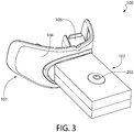
- the teeth whitening system 100 generally comprises a mouthpiece 101 and a housing 102.
- the mouthpiece 101 is sized and shaped so that it can be inserted into the user's oral cavity during use and, thus, can be considered to be intraoral in nature.
- the housing 102 is sized, shaped, and oriented so that it protrudes from the user's oral cavity during use of the teeth whitening system 100 and, thus, can be considered extraoral in nature.
- the housing 102 and the mouthpiece are configured such that the teeth whitening system 100 is a self-contained hands-free device that can put into the oral cavity and supported in the user's mouth simply using one's teeth.
- the housing 102 and the mouthpiece 101 are coupled together so that the mouthpiece 101 extends from the housing 102 in a direction generally opposite the direction in which light is emitted from the mouthpiece 101.
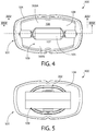
- the mouthpiece 101 (which as discussed below may be formed by a plurality of components) generally comprises a body that includes an arch-shaped wall 104 and a bite platform 105 extending horizontally from the arch-shaped wall 104.
- the arch-shaped wall 104 has a curvature that generally corresponds to the arch of the human dentiture.
- the arch-shaped wall 104 comprises a first light emitting surface 106 that is located above the bite platform 105 and a second light emitting surface 107 that is located below the bite platform 105.
- the first light emitting surface 106 has a concave curvature and is configured to emit light onto a user's maxillary teeth.
- the second light emitting surface 107 also has a concave curvature and is configured to emit light onto a user's mandibular teeth.
- the light emitted by the first and second light emitting surfaces 106, 107 is generated by first and second flexible lamps respectively, the details of which will be described in greater detail below with respect to FIGS. 6-7 and 17-19 .
- the light emitted by the first and second light emitting surfaces 106, 107 may be generated with other light sources that are either embedded in the arch-shaped wall 104 and/or transmitted to the first and second light emitting surfaces 106, 107 using light piping or other suitable techniques.
- the first and second light emitting surfaces 106, 107 are positioned and oriented within the mouthpiece 101 to be positioned close to and optimally oriented relative to the user's maxillary and mandibular teeth when the teeth whitening system 100 is being used.
- the arched wall 104 and the bite platform 105 collectively form a first channel 108 and a second channel 109 for receiving a user's teeth during a tooth whitening session. More specifically, in the illustrated embodiment, an upper portion of the arched wall 104 comprises the first light emitting surface 106 and extends upward from an upper surface of the bite platform 105, thereby forming the first channel 108. A lower portion of the arched wall 104 comprises the second light emitting surface 107 and extends downward from a lower surface of the bite platform 105, thereby forming the second channel 109.
- the mouthpiece 101 is inserted into a user's mouth such that the bite platform 105 is trapped or sandwiched between the user's maxillary and mandibular teeth.
- the first light emitting surface 106 is adjacent to the facial surfaces of the user's maxillary teeth and has a curvature such that the first light emitting surface 106 generally corresponds to at least the anterior portion of the arch of the maxillary teeth.
- the second light emitting surface 107 is adjacent the facial surfaces of the user's mandibular teeth and has a curvature such that the second light emitting surface 107 generally corresponds to at least the anterior portion of the arch of the mandibular teeth.
- the mouthpiece 101 may be designed such that the bite platform 105 is omitted.
- the first and second light emitting surfaces 106, 107 may be maintained as separate and distinct light emitting areas, each of which emits light only onto the facial surfaces of the maxillary teeth and the facial surfaces of the mandibular teeth respectively.
- the first and second light emitting surfaces 106, 107 may be merged into a single light emitting area that emits light onto the facial surfaces of both the maxillary and mandibular teeth.
- the bite platform 105 may be omitted and only a single light emitting surface may be provided that emits light only onto the facial surfaces of the maxillary teeth or only onto the facial surfaces of the mandibular teeth at any given time.
- the bite platform 105 can be included and only one of the first or second light emitting surfaces may be provided.
- the mouthpiece 101 may be formed as two separable components, wherein one component contains the first light emitting surface 106 for emitting light onto the upper teeth and the other component contains the second light emitting surface 107 for emitting light onto the user's lower teeth.
- the mouthpiece 101 (including all of the components thereof that come into contact with the oral cavity) is formed of a biocompatible material, such as a food grade polymer.
- a biocompatible material such as a food grade polymer.
- Suitable biocompatible materials include, without limitation, polyethylene terephthalate (PET), polypropylene (PP), polyethylene naphthalate (PEN), polyethylene (PE), silicone, ethylene propylene diene monomer (EPDM), polycarbonate (PC), thermoplastic elastomers (TPE), and other plastics.
- PET polyethylene terephthalate
- PP polypropylene
- PEN polyethylene naphthalate
- PE polyethylene
- EPDM ethylene propylene diene monomer
- PC polycarbonate
- TPE thermoplastic elastomers
- the invention is not to be so limited in all embodiments and other materials are possible for construction of the mouthpiece 101, and various components thereof.
- the mouthpiece 101, or at least portions thereof may be formed of an elast
- the housing 102 contains a control circuit 200 (see FIG. 25 ).
- the control circuit 200 generally comprises, among other components, a properly programmed processor, a memory device, a power source 201, a timer, and an actuator 202 that are operably coupled together.
- the control circuit 200 is operably and electrically coupled to each of the first and second lamps 300A-B so that the control circuit 200 can control the operation thereof.
- the properly programmed processor may be any suitable microprocessor based programmable logic controller, personal computer, or the like that has memory for storing various instructions to control the operation of the first and second lamps 300A-B.
- the processor is programmed with algorithms to receive data from the various other electrical components and sensors, analyze the data, and cause the electrical components to operate in a desired or predetermined manner based on instructions that are stored in the memory device or an integrated memory area of the processor.
- the power source 201 is operably and electrically coupled to the processor and to the first and second lamps 300A-B so that electrical energy can be provided thereto for powering the same.
- the power source 201 may be one or more batteries, battery cells, printed batteries, rechargeable batteries, super capacitors, or a control circuit that stores electrical energy.
- the power source may be omitted and instead the electronic components of the tooth whitening device 100 may be powered by a plug that is coupled to a power supply, such as a wall socket.
- the teeth whitening device 100 may be part of a larger system that includes a docking station that includes charging capabilities. In one such embodiment, the teeth whitening device 100 is part of a system including docking station that includes a charging circuit configured to charge a rechargeable battery of the teeth whitening device 100 by inductive charging.
- the actuator 202 is a depressible button.
- the invention is not to be so limited and the actuator 202 can be any type of device that upon actuation powers on and/or off one or more of the electrical components stored within the housing 102.
- the actuator 202 can be a slide switch, a touch pad, a knob, or any other component that upon actuation causes the teeth whitening device 100 to function as described herein.
- the actuator 202 can be a sensor or other device that is automatically activated upon the mouthpiece 101 of the teeth whitening device being inserted into the oral cavity, such as a temperature sensor, a water-activated sensor that is activated by saliva, a proximity sensor, a humidity sensor, or any other suitable sensor or switch.
- the actuator 202 is operably coupled to the processor so that upon depressing or otherwise actuating the actuator 202, the processor initiates operation of the teeth whitening system 100 as described in more detail below.
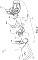
- the mouthpiece 101 of the teeth whitening device 100 is a multi-component structure that generally comprises a curved support plate 400, an anchor component 500, an electrical contact component 50, first and second flexible lamps 300A-B, a lamp retaining component 600, and a guard component 700.
- the mouthpiece 101 may simply comprises single component to which at least one of the first or second lamps 300A-B is mounted as discussed below.
- the first and second flexible lamps 300A-B can be electrically coupled to the control circuit 200 in series or in parallel.
- the housing 102 generally comprises an upper portion 150 and a lower portion 151.
- the upper and lower portions 150, 151 of the housing 150 form an internal chamber 109 in which the electrical components of the control circuit 200 are disposed.
- the internal chamber 109 is sealed so as to prevent the ingress of water and other fluids.
- the housing 102 can be formed of any suitable materials, including hard plastics such as PP or any other hard plastic material described herein. If desired, an elastomeric material, such as a thermoplastic elastomer, can be overmolded to the upper and lower portions 150, 151 of the housing 102. Such overmolding can be used to seal the interface between the upper and lower portions 150, 151 of the housing 102 and/or to provide a gripping surface to the user.
- the housing 101 extends from a proximal end 110 to a distal end 111.
- the distal end 111 is configured to have the mouthpiece 101 coupled thereto.
- the distal end 111 of the housing is flared and comprises an opening 113 through which the mouthpiece 101 extends for mounting to the housing 102.
- the opening 113 is defined by a closed-geometry edge 118 of the distal end 111 of the housing 102.
- the opening 113 forms a passageway into a mounting chamber 119.
- the mounting chamber 119 terminates in a housing wall 114.
- the housing wall 114 separates the mounting chamber 119 of the housing 102 from the internal chamber 109 of the housing 102.
- the housing wall 114 comprises a first anchor aperture 115, a second anchor aperture 116, and an electrical connection aperture 117.
- the housing wall 114 is formed by the combination of an upper wall portion 114A that is part of the upper portion 150 of the housing 102 and a lower wall portion 114B that is part of the lower portion 151 of the housing 102.
- the first and second anchor apertures 115, 116 provide a feature through which the anchor elements 521A-B of the mouthpiece 101 extend, thereby allowing the anchor elements 521A-B to mechanically mate with the housing 101 to fix the mouthpiece 110 to the housing 102.
- the electrical connection aperture 117 forms a passageway from the mounting chamber 119 into the internal chamber 109 so that electrical conductors (discussed in greater detail below) can be run that electrically couple the control circuit 200 to the first and second lamps 300A-B, thereby providing a mechanism through which electrical power from the power source 201 can be provided to the first and second lamps 300A-B.
- an electrical contact component 50 is illustrated according to an example useful for understanding the present invention.
- the electrical contact component 50 is mounted within the mouthpiece 101 and is configured to provide the necessary electrical energy from the power source 201 to each of the flexible lamps 300A-B so that the flexible lamps 300A-B can be activated.
- the electrical contact component 50 generally comprises an integrally formed monolithic base structure 51 formed of a dielectric material.
- the base structure 51 comprises a base section 52 and first, second, and third tabs 53A-C extending from the base section 52.
- Each of the first, second and third tabs 53A-C are elongated in nature and extend parallel to one another in a spaced apart manner.
- Each of the first, second, and third tabs 53A-C are provided with an electrically conductive material, thereby converting each of the first, second, and third tabs 53A-C into first, second, and third electrical contact elements 54A-C respectively.
- the electrically conductive material may in the form of a metallic coating layer, an embedded metallic trace, an embedded wire, or combinations thereof.
- first, second, and third electrical contact elements 54A-C are electrically isolated from one another in one example.
- the first and third electrical contact elements 54A, 54C may be in electrical communication due to the first and third electrical contact elements 54A, 54C carrying the same electrical charge when coupled to the control circuit 200.
- the first and third electrical contact elements 54A, 54C would still be electrically isolated from the second electrical contact element 54B, which carries an electrical charge that is opposite that which is carried by the first and third electrical contact elements 54A, 54C when coupled to the control circuit 200.
- the first electrical contact element 54A comprises a first contact surface 55A.
- the second electrical contact element 54B comprises a second contact surface 55B.
- the third electrical contact element 54C comprises a third contact surface 55C.
- the second contact surface 55B is a stepped surface comprising a first portion 56A and a second portion 56B that are horizontally offset from one another. As discussed below, the first portion 56A of the second contact surface 55B contacts a second electrical contact 312A of the first flexible lamp 300A while the second portion 56B of the second contact surface 55B contacts a second electrical contact 312B of the second flexible lamp 300B.
- the first contact surface 55A contacts only the first electrical contact 311A of the first flexible lamp 300A, while the third contact surface 55C contacts only the first electrical contact 311B of the second flexible lamp 300B.
- the second contact surface 55B may not be stepped and may simply be designed to contact a single electrical contact of one of the first or second lamps 300A-B.
- first, second, and third electrical contact elements 54A-C can be separate and distinct structures.
- each of the first, second, and third electrical contact elements 54A-C can be tabs that are separately mounted within the mouthpiece.
- electrical energy can be supplied to the first and second lamps 300A-B through simple electrical conductors, such as wires and/or trace lines that are embedded within the mouthpiece 101.
- the first electrical conductor is configured to have a first electrical charge
- the second electrical conductor is configured to have a second electrical charge that is opposite the first electrical charge
- the third electrical conductor is configured to have the first electrical charge.
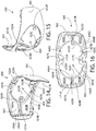
- the anchor component 500 generally comprises a curved plate section 510 and an anchor section 520.
- the anchor section 520 protrudes from a front surface 511 of the curved plate section 510.
- the curved plate section 510 further comprises a rear surface 512 which, as discussed below, forms a portion of a lamp mounting surface when the anchor component 500 and curved support plate 400 are assembled.
- the rear surface 512 of the curved plate section 510 has a concave curvature.
- the concave curvature of the curved plate section 510 is selected to generally correspond to the arch of a user's dentiture, and specifically to the anterior-most portion of said dentiture arch.
- the rear surface 512 of the curved plate section 510 is a stepped surface comprising a first surface portion 512A, a second surface portion 512B, and a tread surface portion 513 extending between the first and second surface portions 512A-B.
- the first surface portion 512A and the second surface portion 512B are horizontally offset from one another so that the first and second lamps 300A-B can be mounted within the mouthpiece 101 in a desired offset and inclined orientation.
- the anchor portion 520 of the anchor component provides a mechanism by which the mouthpiece 101 can be mounted to the housing 102, as is discussed in greater detail below.
- the anchor portion 520 comprises first and second anchor elements 521A, 521B.
- a single anchor element can be utilized to achieve fixation of the mouthpiece 101 to the housing 102.
- Each of the anchor elements 521A-B is illustrated as a peg member having a post portion 522A-B and a head portion 523A-B.
- the head portion 523A-B has an enlarged cross-section as compared to the post section 522A-B, thereby forming a flange (or shoulder) at the end of the post portion 522A-B.
- this flange or shoulder facilitates mechanical mating of the anchor elements 521A-B to the housing wall 114.
- the curved plate section 510 of the anchor component 500 further comprises a central aperture 530.
- the central aperture 530 provides a passageway through the curved plate section 510 through which the second electrical contact element 54B extends when the mouthpiece 101 is assembled.
- the curved plate section 510 further comprises first and second locking apertures 531A-B for receiving snap-fit tabs 630A-B of the lamp retaining component 600 (discussed in greater detail below).
- the locking apertures 531A-B are located along a horizontal centerline of the anchor component 500 which, in the illustrated embodiment extends along the tread surface portion 513.
- the anchor component 500 further comprises first and second lamp retaining features 535A-B.
- the first and second lamp retaining features 535A-B are in the form of angled protuberances that protrude from the upper and lower edges 536, 537 of the curved plate section 510, respectively.
- the first retaining feature 535A is provided to engage an edge of the first flexible lamp 300A while the second retaining feature 535B is provided to engage an edge of the second flexible lamp 300B.
- the anchor component 500 may be formed such that the first and second lamp retaining features 535A-B engage opposite edges of the same flexible lamp.
- the rear surface 512 may not be stepped but rather a continuous and smooth surface.
- the anchor component 500 further comprises a plurality of protuberances 540A-D protruding from the front surface 511 of the curved plate section 510.
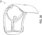
- the protuberances 540A-D are provided as mechanisms to ensure proper alignment and coupling between the anchor component 500 and the curved support plate 400 when these two components are coupled together to collectively form a lamp support structure 1000 (see FIG. 28 ).
- the anchor component 500 is formed of a rigid material, such as PP.
- the curved support plate 400 in combination with the anchor component 500, provides a lamp support structure 1000 that provides a degree of structural rigidity to the mouthpiece 101 for the flexible lamps 300A-B, especially during the manufacturing process.
- the curved support plate 400 is a thin curved plate structure having a front surface 401 and a rear surface 402.
- the curved support plate 400 is formed of a rigid material, such as a hard plastic, such as PP for example.
- the rear surface 402 of the curved support plate 400 forms a portion of the lamp support surface 1001.
- the rear surface 402 of the curved support plate 400 and the rear surface 512 of the anchor component 500 collectively define the lamp support surface 1001 to which the each of the first and second lamps 300A-B is mounted.
- either the anchor component 500 or the curved support plate 400 can be omitted such that the lamp support structure 1000 is formed only by the other one of the anchor component 500 or the curved support plate 400.
- the lamp support structure 1001 can simply be a component having a curved lamp support surface.
- the rear surface 402 of the curved support plate 400 has a concave curvature which, in certain embodiments, generally corresponds to the arch of a user's dentiture.
- the front surface 401 of the curved support plate 400 has a convex curvature.
- the concave curvature of the rear surface 402 matches the convex curvature of the front surface 401 so that the curved support plate has a generally constant thickness along its length.
- the curved support plate 400 comprises a central aperture 403 extending therethrough.
- the central aperture 403 is provided to allow the anchor portion 520 of the anchor component 500 to protrude from the front surface 401 of the curved support plate 400 when the curved support plate 400 and the anchor component 500 are coupled together.
- the front surface 402 of the curved support plate 400 further comprises a plurality of depressions 404A-D formed therein.
- Each of the depressions 404A-D comprises a floor 405A-D and a basin wall 406A-D.
- a channel 407A-D is provided in each of the basin walls 406A-D respectively that forms a passageway between the depressions 404A-D and the central aperture 403.
- the channels 407A-D allow for the flow of melted thermoplastic elastomer during the injection overmolding of the guard component 700 to flow into the depressions 404A-D, thereby forming elastomeric pad portions 770A-D in the depressions 404A-D.
- the curved support plate 400 further comprises a lamp registration feature that maintains the flexible lamps 300A-B in their selected positions relative to the curved support plate 400.
- the lamp registration feature comprises first and second ribs 421A-B that protrude from the rear surface 402 of the curved support plate 400.
- each of the first and second ribs 421A-B comprises two U-shaped rib sections that are designed to engage the corners of the first and second flexible lamps 300A-B.
- the lamp registration feature is illustrated as two ribs, the lamp registration feature can take on a wide variety of structures, such as, without limitation, posts, notches, tabs, overhangs, and combinations thereof
- the curved support plate 400 also comprises a plurality of apertures 422A-D that are provided to mate with the plurality of protuberances 540A-D of the anchor component 500 when the curved support plate 400 and the anchor component 500 are coupled together.
- the apertures 422A-D are located on tabs 423-D that extend into the central aperture 403. In other embodiments, the apertures 422A-D may be located elsewhere on the curved support plate 400.
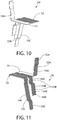
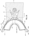
- first and second lamps 300A-B according to the present invention are illustrated. While only the cross-section of the first lamp 30A is shown in FIG.19 , it is to be understood that the second lamp 300b has the same laminate structure as that of the first lamp 300A.
- Each of the first and second lamps 300A-B comprise a flexible sheet body 301A-B respectively.
- the flexible sheet body 301A-B of each of the first and second lamps 300A-B is an elongated sheet that is sufficiently flexible such that it can be bent from a planar state into a contoured shape having a curvature that generally corresponds to the arch of a user's dentiture.
- the flexible sheet body 301A-B of each of the first and second lamps 300A-B is in a planar state when no bending force is applied to the lamp 300A-B.
- the flexible sheet body 301A-B of each of the first and second lamps 300A-B generally comprises a front surface 302A-B and a rear surface 303A-B.
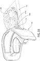
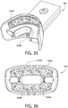
- Each of the first and second lamps 300A-B also comprises a plurality of light emitters 304A-B embedded within the flexible sheet body 301A-B that generate light which is emitted from the rear surface 303A-B of the flexible sheet body 301A-B (see FIGS. 34-35 also).
- the light emitted by the plurality of light emitters 304A-B has a wavelength in a range of 375 nm to 520 nm.
- the light emitted by the plurality of light emitters 304A-B has a wavelength in a range of 400 nm to 430 nm. In a further embodiment, the light emitted by the plurality of light emitters 304A-B has a wavelength in a range of 405 nm to 415 nm.
- the flexible sheet body 301A-B of each of the first and second lamps 300A-B comprises an upper edge 305A-B, a lower edge 306A-B, a first side edge 307A-B, and a second side edge 308A-B.
- the flexible sheet body 301A-B of each of the first and second lamps 300A-B also comprises a length measured from the first side edge 307A-B to the second side edge 308A-B.
- the flexible sheet body 301A-B of each of the first and second lamps 300A-B is a laminate structure that generally comprises a flexible lens plate 309A-B, a flexible reflective layer 310A-B, and first and second electrical contacts 311A-B, 312A-B.
- the plurality of light emitters 304A-B are disposed between the flexible lens plate 309A-B and the flexible reflective layer 310A-B.
- the plurality of light emitters 340A-B may be printed directly to the flexible lens plate 309A-B in certain embodiments.
- the flexible reflective layer 310A-B may also be printed onto the flexible lens plate 309A-B subsequent to the plurality of light emitters 340A-B.
- the flexible lens plate 309A-B of the flexible sheet body 301A-B of each of the first and second lamps 300A-B has a rear surface 313A-B and a front surface 314A-B.
- the rear surface 313A-B of the flexible lens plate 309A-B forms the rear surface 303A-B of the flexible sheet body 301A-B of each of the first and second lamps 300A-B.
- the flexible lens plate 309A-B may be formed of a transparent biocompatible material, such as transparent PET.
- the plurality of light emitters 304A-B are light emitting diodes ("LEDs") printed to the front surface 314A-B of the flexible lens plate 309A-B of the flexible sheet body 301A-B of each of the first and second lamps 300A-B.
- the LEDs may be printed to the front surface 314A-B with an electrically conductive ink 315A-B.
- Printed LEDs may be formed by depositing micro LED chips via a conductive ink formulation that can be printed in any shape to best conform to the teeth and jaw structure, which is ideal for optimized efficacy.
- gallium nitride may be used to form the LEDs in some embodiments, which may then be mixed with resin and binders to form an ink, and a standard screen printer may be used to deposit the resulting ink over a desired surface.
- the plurality of light emitters 304A-B may, in certain embodiments, be any type of light source, particularly solid state light sources, which may include LEDs, OLEDs, HBLEDs, electroluminescent elements, or the like.
- the plurality of light emitters 304A-B can be printed inorganic LEDs, micro conventional LEDs that are surface mounted to a flexible substrate/circuit, organic LEDs (OLEDs), or electroluminescence. In still other embodiments, the plurality of light emitters 304A-B can be any of the LEDs noted herein mounted to a rigid rather than a flexible substrate.
- the first electrical contact 311A-B has a first contact surface 316A-B that forms a first portion of the front surface 302A-B of the flexible sheet body 301A-B.
- the second electrical contact 312A-B has a second contact surface 317A-B that forms a second portion of the front surface 302A-B of the flexible sheet body 301A-B.
- each of the first and second electrical contacts 311A-B, 312A-B is in the form of an elongated strip that extends the entire length of the lamp 300A-B.
- the first electrical contact 311A is adjacent the upper edge 305A while the second electrical contact 312A is adjacent the lower edge 306A.
- the first electrical contact 311B is adjacent the lower edge 306B while the second electrical contact 312B is adjacent the upper edge 305B.
- the first electrical contact 311A-B extends generally parallel to and second electrical contact 312A-B.
- each of the first and second lamps 300A, 300B has an illumination area (i.e., area of the rear surface 303A-B that comprises plurality of light emitters 304A-B) that is in a range of 6 cm2 to 11 cm2, more preferably in a range of 7 cm2 to 10 cm2, and most preferably in a range of 8 cm2 to 9 cm2.
- the height of illumination area may be in a range of 0.5 cm2 to 3 cm2, and more preferably 0.5 cm2 to 2 cm2, with 1 cm2 being most preferred.
- the length of illumination area may be in a range of 6 cm to 11 cm, more preferably in a range of 7 cm to 10 cm, and most preferably in a range of 8 cm to 9 cm.
- a lamp retaining component 600 is illustrated according to an example useful for understanding the present invention.
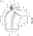
- the lamp retaining component 600 is used to retain the first and second lamps 300A-300B to the lamp support surface 1001 when the mouthpiece is assembled (and during the injection molding of the guard component 700 to the lamp assembly 2000).
- the lamp retaining component 600 in one example, is formed of a rigid material, such as a hard plastic.
- Suitable hard plastics include without limitation polymers and copolymers of ethylene (polyethylene), propylene (polypropylene), butadiene, polyamide, cellulosic, SAN, acrylic, ABS, vinyl compounds, and polyesters such as polyethylene terephthalate, or other commonly known thermoplastics used in oral hygiene device manufacture.
- the lamp retaining component 600 generally comprises a lamp engagement portion 610 and a plate portion 620.
- the lamp engagement portion 610 comprises a first arched surface 611 that contacts the lower portion of the first lamp 300A and a second arched surface 612 that contacts the upper portion of the second lamp 300B.
- the first and second arched surfaces 611, 612 of the lamp retaining component 600 are also horizontally offset from one another in certain examples.
- the lamp retaining component 600 further comprises a locking feature that locks the lamp retaining component 600 to the anchor component 500 to ensure that the lamps 300A-B are compressed therebetween and/or held in place.
- the locking feature of the lamp retaining component 600 comprises first and second locking tabs 630A-B, which are configured to snap-lock to the anchor component 500. More specifically, the lamp retaining component 600 is coupled to the anchor component by inserting the first and second locking tabs 630A-B through the locking apertures 531A-B of the anchor component 500.
- the chamfered surfaces 631A-B of the first and second locking tabs 630A-B contact the rear surface 512 of the curved plate section 510 of the anchor component 500 and deflect the first and second locking tabs 630A-B.
- the first and second locking tabs 630A-B snap back into their normal state, thereby causing locking surfaces 632A-B of the first and second locking tabs 630A-B to mate with and mechanically engage an edge portion of the curved plate section 510 of the anchor component 500 that defines the locking apertures 531A-B of the anchor component 500.
- the plate portion 620 is a flat plate structure that extends horizontally from the lamp engagement section 610.
- the plate portion 620 of the lamp retaining component 600 extends horizontally from the lamp support surface 1001 (see FIG. 30 ).
- the lamp retaining component 600 is embedded in the bite platform of the mouthpiece 101 when the mouthpiece is fully assembled in certain examples.
- the lamp retaining component 600 also assists with maintaining the proper contour of the arch-shaped wall 104 of the mouthpiece 101.
- the lamp retaining component 600 may be omitted all together. In such an embodiment, the function of the lamp retaining component 600 may be performed by the guard component. In other examples, the lamp retaining component 600 may be integrated into the lamp support structure. In another example, the lamp support structure may include a plat portion, similar to plat portion 620 that protrudes from the lamp support surface.
- the guard component 700 in the illustrated embodiment, is an integrally formed monolithic component.
- the guard component 700 is formed of a material so as to provide comfort to the user when the mouthpiece 101 is inserted into the oral cavity.
- the material of which the guard component 700 is formed has a hardness value that is less than the hardness value of the material (or materials) of which the lamp support structure 1000 is formed (in the illustrated embodiment the lamp support structure 1000 is formed by the combination of the anchor component 500 and the curved support plate 400, but may be a singular component in other embodiments).
- the guard component 700 is formed of an elastomeric material. Suitable elastomeric materials include, without limitation, thermoplastic elastomers, rubbers, silicones, or other biocompatible resilient materials suitable for uses in an oral hygiene apparatus including thermoset elastomers or the like.
- the guard component 700 generally comprises a wall portion 750 and a bite platform portion 760.
- the bite platform portion 760 extends horizontally from the wall portion 750.
- the wall portion 750 can conceptually be divided into an upper wall portion 751 and a lower wall portion 752.
- the bite platform portion 760 is located between the upper and lower wall portions 751-752. In other embodiments, the bite platform portion 760 may be omitted.
- the wall portion 750 comprises a central portion 710 and first and second wing portions 720A-B.
- the central portion 710 is arcuate in shape and has a curvature that corresponds to the anterior portion of the arch of the human dentiture.
- the first and second wing portions 720A-B extend from and are located on opposite sides of the central portion 710, thereby generally continuing the curvature that corresponds to the arch of the human dentiture.
- the first and second wing portions 720A-B in certain embodiments, are formed entirely out of the elastomeric material in order to ensure flexibility for user comfort. In certain such embodiments, the first and second wing portions 720A-B retain their flexible nature as the lamp support structure 1000 does not extend into the first and second wing portions 720A-B but rather are only located in the central portion 710.
- the central portion 710 comprises a first frame portion 711 and a second frame portion 712. More specifically, the upper wall portion 751 comprises the first frame portion 711 while the lower wall portion 752 comprises the second frame portion 712.
- the first frame portion 711 comprises a closed-geometry edge 713 that defines a first window 714 through which the rear surface 303A of the first lamp 300A remains exposed when the mouthpiece 101 is assembled.
- the second frame portion 712 comprises a closed-geometry edge 715 that defines a second window 716 through which the rear surface 303B of the second lamp 300B remains exposed when the mouthpiece 101 is assembled.
- the first frame portion 711 seals a perimeter of the rear surface 303A of the first lamp 300A while the second frame portion 712 seals a perimeter of the rear surface 303B of the second lamp 300B.
- the guard component 700 further comprises a plurality of pad portions 770A-D.
- the plurality of pad portions 770A-D are respectively disposed in the plurality of depressions 404A-D of the curved support plate 400. Allowing molten elastomeric material to flow into the depressions to form the plurality of pad portions 770A-D assists in equalizing pressure on the first and second lamps 300A-B during the injection molding process in which the guard component 700 is overmolded to the lamp support structure 1000.
- first and second pad portions 770A-B are located within the first window 714 while the third and fourth pad portions 770C-D are located within the second window 716.
- the first and second pad portions 770A-B are located within the first and second depressions 404A-B respectively and contact both the floors 405A-B of the first and second depressions 404A-B and the front surface 312A of the first lamp 300A.
- the third and fourth pad portions 770C-D are located within the third and fourth depressions 404C-D respectively and contact both the floors 405C-D of the third and fourth depressions 404C-D and the front surface 312B of the second lamp 300B.
- the curved support plate 400 is formed out of a first material, such as a hard plastic, using an injection molding or other suitable process.
- a first material such as a hard plastic
- Suitable hard plastics include without limitation polymers and copolymers of ethylene (polyethylene), propylene (polypropylene), butadiene, polyamide, cellulosic, SAN, acrylic, ABS, vinyl compounds, and polyesters such as polyethylene terephthalate, polycarbonate (or blends thereof) or other commonly known thermoplastics used in oral hygiene device manufacture.
- the first material may be another suitable rigid material that can properly support and protect the flexible lamps 300A-B during the injection molding process of the guard component 700 (discussed below).
- the anchor component 500 is provided and coupled to the curved support plate 400, thereby forming a lamp support structure 1000. Because the lamp support structure 1000 is formed by the combination of the anchor component 500 and the curved support plate 400, it should be noted that for purposes of this patent, it can be said that the lamp support structure 1000 comprises the various features of either of these components as described above for FIGS. 12-13 and 14-16 .
- the anchor section 510 of the anchor component 500 is inserted through the central aperture 403 of the curved support plate 400.
- the plurality of protuberances 540A-D protruding from the front surface 511 of the anchor component 500 respectively enter the plurality of apertures 422A-D of the curved support plate 400, thereby ensuring proper relative alignment and mating between the anchor component 500 and the curved support plate 400.
- the electrical contact component 50 has been previously mounted to the anchor component 500, prior to mounting to the curved support plate 400.
- the electrical contact component 50 is already mounted and integrated into the lamp support structure 1000.
- the lamp support structure 1000 in the illustrated embodiment, is formed by the combination of the anchor component 400 and the curved support plate 500, the lamp support structure 1000 may be an integrally-formed single component structure in other embodiments. In still other embodiments, more than two components can be used to form the lamp support structure 1000.
- the lamp support structure 1000 comprises a lamp support surface 1001 (which is formed by the combination of the rear surfaces 402, 512 of the curved support plate 400 and anchor component 500 in the illustrated embodiment).
- the lamp support surface 1001 has a concave curvature which, in one embodiment, generally corresponds to the arch of the human dentiture.
- the lamp support structure 1000 further comprises a front surface 1002 (which is formed by the combination of the front surfaces 401, 511 of the curved support plate 400 and anchor component 500 in the illustrated embodiment).
- the lamp support structure 1000 comprises a curved plate section 1010 that has a first thickness measured from the front surface 1002 to the lamp support surface 1001.
- each of the first and second lamps 300A-B have a second thickness measured from the rear surface 303A-B of the flexible sheet body 301A-B to the front surface 302A-B of the flexible sheet body 301A-B. In one embodiment, a ratio of the first thickness to the second thickness is in a range 0.5 to 2.5.
- the lamp support structure 1000 comprises an upper curved edge 1003, a lower curved edge 1004, a first side edge 1005 extending between the upper and lower curved edges 1003, 1004, and a second side edge 1006 extending between the upper and lower curved edges.
- the anchor elements 521A-B protrude from the front surface 1002 of the lamp support structure 1000.
- the lamp support structure 1000 further comprises the lamp registration feature 421A-B, the lamp retaining feature 535A-B, and the depressions 405A-D formed in the lamp support surface 1001, as described in greater detail above with respect to FIGS. 12-13 and 14-16 .
- the electrical contact component 50 is mounted to the lamp support structure 1000 so that electrical coupling of the first and second lamps 300A-B can be easily accomplished. Specifically, electrical contact component 50 is mounted to the lamp support structure 1000 so that: (1) the first contact surface 55A of the first electrical contact element 54A forms a portion of the lamp support surface 1001; (2) the second contact surface 55B of the second electrical contact element 54B forms a portion of the lamp support surface 1001; and (3) the third contact surface 55C of the third electrical contact element 54C forms a portion of the lamp support surface 1001. In one embodiment, the first, second and third contact surfaces 55A-C of the electrical contact component 50 are substantially flush with the remainder of the lamp support surface 1001.
- each of the first, second and third contact surfaces 55A-C of the electrical contact component 50 are located in a central portion (horizontally) of the lamp support structure, wherein the second contact surface 55B of the second electrical contact element 54B is centrally located (vertically) while the first contact surface 55A of the first electrical contact element 54A is located adjacent the upper curved edge 1003 and the third contact surface 55C of the third electrical contact element 54C is located adjacent the lower curved edge 1004.
- the lamp support structure 1000 is a stepped surface in the central region, with the tread surface portion 513 forming the step between the upper and lower surface portions 512A, 512B, which are horizontally offset from one another.
- the upper surface portion 512A can be considered a first riser portion of the lamp support surface 1001 while the lower surface portion 512B can be considered a second riser portion of the lamp support surface 1001.
- the second contact surface 55B is also a stepped surface comprising a first portion 56A and a second portion 56B that are horizontally offset from one another.
- the first portion 56A of the second contact surface 55B is in surface alignment with the upper surface portion 512A while the second portion 56B of the second contact surface 55B is in surface alignment with the lower surface portion 512B.
- the first and second lamps 300A-B are mounted to the lamp support surface 1001 of the lamp support structure 1000, thereby forming a lamp assembly 2000. Because the first and second lamps 300A-B are flexible, the lamps 300A-B flex to assume the curvature of the lamp mounting surface 1001, thereby resulting in the rear surfaces 313A-B of the flexible sheet bodies 301A-B of the first and second lamps 300A-B assuming a concave curvature. The first lamp 300A is mounted above the second lamp 300B.
- the first and second electrical contacts 311A-B, 312A-B of the lamps 300A-B come into surface contact with the contact surfaces 55A-C of the first, second, and third electrical contact elements 54A-C.
- the first contact surface 55A of the first electrical contact element 54A is in surface contact with the first electrical contact 311A of the first lamp 300A.
- the third contact surface 55C of the third electrical contact element 54C is in surface contact with the first electrical contact 311B of the second lamp 300B.
- the first portion 56A of the second contact surface 55B contacts a second electrical contact 112A of the first flexible lamp 300A while the second portion 56B of the second contact surface 55B contacts a second electrical contact 112B of the second flexible lamp 300B.
- the surface contact between the contact surfaces is sufficient to achieve the desired electrical coupling and, thus electrical coupling is achieved solely through surface contact.
- the contact surfaces may be soldered together to increase reliability.
- the electrical contact component 50 has a portion 75 that protrudes from the front surface 1002 of the lamp support structure 1000 adjacent the anchor elements 521A-B.
- the portion 75 comprises an exposed portion of each of the first, second, and third electrical conductors 54A-C to facilitate coupling to the control circuit 200 (discussed below).
- the lamp registration feature 421A-B and the lamp retaining feature 535A-B Proper positioning (and maintaining proper position) of the flexible lamps 300A-B to the lamp support structure 100 is achieved by the lamp registration feature 421A-B and the lamp retaining feature 535A-B.
- the lamp registration feature comprises first and second ribs 421A-B that protrudes from the lamps support surface 1001.
- the second rib 421A engages first and second corners of the flexible sheet bodies 301A-B of each of the first and second lamps 300A-B while the second rib 421B engages third and fourth corners of the flexible sheet bodies 301A-B of each of the first and second lamps 300A-B.
- first and second lamp retaining features 535A-B also protrude from the lamp support surface, wherein the first retaining feature 535A engages the upper edge 305A of the first flexible lamp 300A while the second retaining feature 535B engages the lower edge 306B of the second flexible lamp 300B.
- first retaining feature 535A extends through a notch 375A formed in the upper edge 305A of the first flexible lamp 300A while the second retaining feature 535B extends through a notch 375B formed in the lower edge 306B of the second flexible lamp 300B.
- the lamp retaining component 600 is aligned with the lamp support structure 1000 and coupled thereto. Specifically, the lamp retaining component 600 is aligned with the lamp support structure 1000 so that the first and second locking tabs 630A-B are aligned with the locking apertures 531A-B of the lamp support structure 1000. The lamp retaining component 600 is moved towards the lamp support surface 1001 so that the first and second locking tabs 630A-B are inserted through the locking apertures 531A-B of the anchor component 500.
- the chamfered surfaces 631A-B of the first and second locking tabs 630A-B contact the lamp support surface 1001 and deflect the first and second locking tabs 630A-B.
- the first and second locking tabs 630A-B snap back into their normal state, thereby causing locking surfaces 632A-B of the first and second locking tabs 630A-B to mate with and mechanically engage the front surface 1002 of the lamp support structure 1000.
- the first arched surface 611 of the lamp retaining component 600 contacts the lower portion of the first lamp 300A while the second arched surface 612 of the lamp retaining component 600 contacts the upper portion of the second lamp 300B.
- the lamps 300A-B are pressed against the lamp support surface 1001.
- the lower portion of the first lamp 300A may be compressed between the lamp retaining component 600 and the lamp support surface 1001 while the upper portion of the second lamp 300B is compressed between the lamp retaining component 600 and the lamp support surface 1001.
- the guard component 700 is overmolded to the lamp assembly 2000, thereby forming the mouthpiece 101.
- the guard component 700 comprises the first and second frame portions 711, 712.
- the first frame portion 711 comprises the closed-geometry edge 713 that defines the first window 714 through which the rear surface 303A of the first lamp 300A remains exposed.
- the rear surface 303A of the first lamp 300A (which is also the rear surface 313A of the flexible lens plate 309A) also acts as the first light emitting surface 106.
- the second frame portion 712 comprises the closed-geometry edge 715 that defines the second window 716 through which the rear surface 303B of the second lamp 300B remains exposed when the mouthpiece 101 is assembled.
- the rear surface 303B of the second lamp 300B (which is also the rear surface 313B of the flexible lens plate 309B) also acts as the second light emitting surface 107.
- the first frame portion 711 forms an annular seal about the perimeter of the rear surface 303A of the first lamp 300A.
- the second frame portion 712 forms an annular seal about the perimeter of the rear surface 303B of the second lamp 300B.
- molten elastomeric material flows into the depressions 405A-D of the lamps support surface 1001, thereby forming the pad portions 770A-D. Allowing molten elastomeric material to flow into the depressions 405A-D to form the plurality of pad portions 770A-D assists in equalizing pressure on the first and second lamps 300A-B during the injection molding process in which the guard component 700 is overmolded to the lamp support structure 1000.
- the first and second pad portions 770A-B are located within the first and second depressions 404A-B respectively and contact both the floors 405A-B of the first and second depressions 404A-B and the front surface 312A of the first lamp 300A.
- the third and fourth pad portions 770C-D are located within the third and fourth depressions 404C-D respectively and contact both the floors 405C-D of the third and fourth depressions 404C-D and the front surface 312B of the second lamp 300B.
- the guard component 700 further comprises the first wing portion 720A that extends beyond the first side edge 1005 of the lamp support structure 100 and the second wing portion 720B that extends beyond the second side edge 1006 of the lamp support structure 1000.
- the first and second wing portions 720A-B are formed entirely out of the elastomeric material, thereby providing flexibility at the end portions of the mouthpiece 101 for user comfort.
- the lamp support structure 1000 does not extend into the first and second wing portions 720A-B. However, as can be seen, once the guard component 700 is formed, at least a portion of the front surface 1002 of the lamp support structure 1000 remains exposed.
- the mouthpiece 101 is coupled to the housing 102, thereby fixing the mouthpiece 101 to the housing 102 and sealing all electrical components.
- the lower portion 151 of the housing 102 is provided with the control circuit 200 in position.
- the mouthpiece 101 is positioned so that the anchor elements 521A, 521B are above first and second open slots 198A-B formed into a lower section of the housing wall 114.
- the mouthpiece 101 is lowered so that the anchor elements 521A, 521B enter into the first and second open slots 198A-B, wherein the post sections 522A-B extend through the first and second open slots 198A-B and the head portions 523A-B are coated on the opposite side of the housing wall 114.
- the upper portion 150 of the housing 102 is then positioned atop the lower portion 151 of the housing 102.
- the upper portion 150 comprises an upper section of the housing wall that also includes open slots that, when coupled to the lower portion 151, complete the housing wall 114 and form the first and second anchor apertures 116, 117.
- the mouthpiece 101 is designed, in certain embodiments, such that the first light emitting surface 106 and the second light emitting surface 107 are located on opposite sides of a horizontal reference plane H-H.
- the first light emitting surface 106 is inclined so that a first acute angle ⁇ 1 is formed between with the first light emitting surface 106 and the horizontal reference plane H-H.
- the second light emitting surface 107 is inclined so that a second acute angle ⁇ 2 is formed between with the second light emitting surface 107 and the horizontal reference plane H-H.
- the bite platform 105 extends from the first and second light emitting surfaces 106, 107 along the horizontal reference plane H-H.
- the first and second acute angles ⁇ 1, ⁇ 2 are different from one another.
- the first and second acute angles ⁇ 1, ⁇ 2 are the same.
- Each of the first and second acute angles ⁇ 1, ⁇ 2 are in a range of 75° to 89°.
- the lower edge 306A of the first lamp 300A is horizontally offset from the upper edge 305B of the second lamp 300B.
- the first and second lamps 200A-B are horizontally offset from one another such that the first lamp 300A is closer to the housing 102 than the second lamp 300B when measured along the reference plane H-H.
- the body of the mouthpiece 101 can be formed of a singular component that comprises a lamps support surface to which the first and/or second lamps are mounted.
- ranges are used as shorthand for describing each and every value that is within the range. Any value within the range can be selected as the terminus of the range. In the event of a conflict in a definition in the present disclosure and that of a cited reference, the present disclosure controls.
Landscapes
- Health & Medical Sciences (AREA)
- General Health & Medical Sciences (AREA)
- Veterinary Medicine (AREA)
- Public Health (AREA)
- Life Sciences & Earth Sciences (AREA)
- Animal Behavior & Ethology (AREA)
- Biomedical Technology (AREA)
- Engineering & Computer Science (AREA)
- Epidemiology (AREA)
- Dentistry (AREA)
- Oral & Maxillofacial Surgery (AREA)
- Radiology & Medical Imaging (AREA)
- Nuclear Medicine, Radiotherapy & Molecular Imaging (AREA)
- Pathology (AREA)
- Dental Tools And Instruments Or Auxiliary Dental Instruments (AREA)
- Radiation-Therapy Devices (AREA)
- Non-Portable Lighting Devices Or Systems Thereof (AREA)
- Surgical Instruments (AREA)
- Apparatus For Radiation Diagnosis (AREA)
- Medicines That Contain Protein Lipid Enzymes And Other Medicines (AREA)
Claims (15)
- Orale Behandlungsvorrichtung, umfassend:
ein intraorales Mundstück (101), umfassend:eine Lampentragestruktur (1000), umfassend eine Lampentragefläche (1001) mit einer konkaven Krümmung und eine Vorderfläche (401) mit einer konvexen Krümmung, wobei die Lampentragestruktur (1000) aus einem ersten Material gebildet ist;eine Lampe (300A-B), umfassend: einen flexiblen Plattenkörper (301A-B) mit einer Vorderfläche (302A-B) und einer Rückfläche (303A-B); und eine Mehrzahl von Lichtabgabeelementen (304A-B), die in den flexiblen Plattenkörper (301A-B) eingebettet sind und Licht erzeugen, das von der Rückfläche (303A-B) des flexiblen Plattenkörpers (301A-B) abgegeben wird; wobei die Lampe (300A-B) an der Lampentragefläche (1001) der Lampentragestruktur (1000) befestigt ist, sodass die Rückfläche (303A-B) des flexiblen Plattenkörpers (301A-B) der Lampe (300A-B) eine konkave Krümmung annimmt, wodurch eine Lampenanordnung (2000) gebildet wird, wobei die Lampe (300A-B) mit einer Steuerschaltung mit einer Energiequelle wirkverbunden ist; undeine Schutzkomponente (700), die über die Lampenanordnung (2000) überspritzt ist, wobei:die Schutzkomponente (700) aus einem elastomeren Material mit einer Härte gebildet ist, die geringer als eine Härte des ersten Materials ist; dadurch gekennzeichnet, dassdie Schutzkomponente (700) einen Rahmenabschnitt (711) umfasst, der einen Umfang der Rückfläche (303A-B) des flexiblen Plattenkörpers (301A-B) der Lampe (300A-B) abdichtet, wobei der Rahmenabschnitt (711) der Schutzkomponente (700) ein Fenster (714, 716) definiert, durch das die Rückfläche des flexiblen Plattenkörpers (301A-B) der Lampe (300A-B) freigelegt bleibt. - Orale Behandlungsvorrichtung nach Anspruch 1, wobei die Lampentragestruktur (1000) eine Lampenregistrierungseinrichtung (421A-B) umfasst, die die Lampe (300A-B) in einer ausgewählten Position in Bezug auf die Lampentragestruktur (1000) hält.
- Orale Behandlungsvorrichtung nach Anspruch 2, wobei die Lampenregistrierungseinrichtung (421A-B) umfasst: eine erste Rippe (421A), die von der Lampentragefläche vorsteht und mit einer ersten und einer zweiten Ecke des flexiblen Plattenkörpers der Lampe in Eingriff steht; und eine zweite Rippe (421B), die von der Lampentragefläche (1001) vorsteht und mit einer dritten und einer vierten Ecke des flexiblen Plattenkörpers der Lampe (300A-B) in Eingriff steht.
- Orale Behandlungsvorrichtung nach einem der Ansprüche 1 bis 3, wobei die Lampentragestruktur (1000) ferner mindestens eine in der Lampentragefläche (1001) der Lampentragestruktur gebildete Vertiefung umfasst; und wobei die Schutzkomponente (700) einen Polsterabschnitt in der Vertiefung umfasst, der mit einem Boden der Vertiefung und der Vorderfläche des flexiblen Plattenkörpers (301A-B) der Lampe (300A-B) in Kontakt steht.
- Orale Behandlungsvorrichtung nach einem der Ansprüche 1 bis 4, wobei die Schutzkomponente (700) eine einstückig gebildete, monolithische Masse des elastomeren Materials ist.
- Orale Behandlungsvorrichtung nach einem der Ansprüche 1 bis 5, wobei die Lampentragestruktur (1000) eine obere gekrümmte Kante, eine untere gekrümmte Kante, eine sich zwischen der oberen und der unteren gekrümmten Kante erstreckende erste Seitenkante und eine sich zwischen der oberen und der unteren gekrümmten Kante erstreckende zweite Seitenkante umfasst; und wobei die Schutzkomponente (700) ferner einen ersten Flügelabschnitt (720A), der sich über die erste Seitenkante der Lampentragestruktur (1000) hinaus erstreckt, und einen zweiten Flügelabschnitt (720B), der sich über die zweite Seitenkante der Lampentragestruktur hinaus erstreckt, umfasst.
- Orale Behandlungsvorrichtung nach einem der Ansprüche 1 bis 6, wobei die Lampentragestruktur (1000) einen gekrümmten Plattenabschnitt mit einer von der Lampentragefläche (1001) zu der Vorderfläche der Lampentragestruktur (1000) gemessenen ersten Dicke umfasst; wobei die Lampe (300A-B) eine von der Rückfläche des flexiblen Plattenkörpers (301A-B) zu der Vorderfläche des flexiblen Plattenkörpers (301A-B) gemessene zweite Dicke aufweist; und wobei ein Verhältnis der ersten Dicke zu der zweiten Dicke in einem Bereich von 0,5 bis 2,5 liegt.
- Orale Behandlungsvorrichtung nach einem der Ansprüche 1 bis 7, wobei zumindest ein Abschnitt der Vorderfläche der Lampentragestruktur (1000) freigelegt bleibt.
- Orale Behandlungsvorrichtung nach einem der Ansprüche 1 bis 8, ferner umfassend:ein Gehäuse, das die Steuerschaltung enthält; undwobei das intraorale Mundstück mit dem Gehäuse verbunden ist und sich davon erstreckt; undwobei die Lampentragestruktur (1000) ein Ankerelement (521A-B) umfasst, das sich von der Vorderfläche des Lampentragestruktur (1000) erstreckt und sich mit dem Gehäuse zusammenfügt, um das intraorale Mundstück an dem Gehäuse zu befestigen.
- Orale Behandlungsvorrichtung nach einem der Ansprüche 1 bis 9, wobei die Lampentragestruktur (1000) eine Ankerkomponente (521A-B) und eine gekrümmte Trageplatte umfasst, die miteinander verbunden sind, um gemeinsam die Lampentragestruktur zu definieren.
- Orale Behandlungsvorrichtung nach einem der Ansprüche 1 bis 10, wobei die Lampentragestruktur (1000) ferner eine Lampenhalteeinrichtung (535A-B) umfasst, das mit einer oberen oder unteren Kante der Lampe (300A-B) in Eingriff steht, wobei sich die Lampenhalteeinrichtung (535A-B) durch einen Einschnitt in der oberen oder unteren Kante der Lampe erstreckt.
- Orale Behandlungsvorrichtung nach einem der Ansprüche 1 bis 11, wobei der flexible Plattenkörper (301A-B) der Lampe (300A-B) eine flexible Linsenplatte (309A-B) mit einer Vorderfläche und einer Rückfläche umfasst; und wobei die Mehrzahl von Lichtabgabeelementen (304A-B) auf die Vorderfläche der flexiblen Linsenplatte (309A-B) gedruckte Leuchtdioden sind, wobei die Rückfläche der Linsenplatte die Rückfläche des flexiblen Plattenkörpers (301A-B) der Lampe (300AB) bildet.
- Orale Behandlungsvorrichtung nach Anspruch 12, wobei die Leuchtdioden Licht mit einer Wellenlänge in einem Bereich von 375 nm bis 520 nm abgeben.
- Orale Behandlungsvorrichtung nach Anspruch 13, wobei die Leuchtdioden Licht mit einer Wellenlänge in einem Bereich von 405 nm bis 415 nm abgeben.
- Orale Behandlungsvorrichtung nach einem der Ansprüche 1 bis 14, wobei der flexible Plattenkörper (301A-B) der Lampe (300A-B) einen ersten und einen zweiten elektrischen Kontakt (311A-B, 312A-B) zum Zuführen von elektrischer Energie von der Energiequelle an die Mehrzahl von Lichtabgabeelementen umfasst,
wobei der erste elektrische Kontakt (311A-B, 312A-B) ein länglicher Streifen ist, der sich entlang einer Länge der Lampe neben einer oberen Kante der Lampe erstreckt und der zweite elektrische Kontakt (311A-B, 312A-B) ein länglicher Streifen ist, der sich entlang der Länge der Lampe neben einer unteren Kante der Lampe erstreckt, wobei der erste und der zweite elektrische Kontakt (311A-B, 312A-B) elektrisch voneinander getrennt sind, und
wobei jeder des ersten und des zweiten elektrischen Kontakts (311A-B, 312A-B) eine Kontaktfläche aufweist, die einen Abschnitt der Vorderfläche des flexiblen Plattenkörpers (301A-B) der Lampe (300A-B) bildet.
Priority Applications (3)
| Application Number | Priority Date | Filing Date | Title |
|---|---|---|---|
| EP25208809.1A EP4656158A3 (de) | 2015-12-22 | 2016-12-19 | Orale behandlungsvorrichtung |
| EP19188831.2A EP3583914B1 (de) | 2015-12-22 | 2016-12-19 | Orale behandlungsvorrichtung |
| EP21156747.4A EP3881798B1 (de) | 2015-12-22 | 2016-12-19 | Orale behandlungsvorrichtung |
Applications Claiming Priority (2)
| Application Number | Priority Date | Filing Date | Title |
|---|---|---|---|
| US14/979,064 US10369375B2 (en) | 2015-12-22 | 2015-12-22 | Oral treatment device |
| PCT/US2016/067573 WO2017112597A2 (en) | 2015-12-22 | 2016-12-19 | Oral treatment device |
Related Child Applications (4)
| Application Number | Title | Priority Date | Filing Date |
|---|---|---|---|
| EP19188831.2A Division EP3583914B1 (de) | 2015-12-22 | 2016-12-19 | Orale behandlungsvorrichtung |
| EP19188831.2A Division-Into EP3583914B1 (de) | 2015-12-22 | 2016-12-19 | Orale behandlungsvorrichtung |
| EP25208809.1A Division EP4656158A3 (de) | 2015-12-22 | 2016-12-19 | Orale behandlungsvorrichtung |
| EP21156747.4A Division EP3881798B1 (de) | 2015-12-22 | 2016-12-19 | Orale behandlungsvorrichtung |
Publications (2)
| Publication Number | Publication Date |
|---|---|
| EP3376993A2 EP3376993A2 (de) | 2018-09-26 |
| EP3376993B1 true EP3376993B1 (de) | 2019-10-09 |
Family
ID=57777713
Family Applications (4)
| Application Number | Title | Priority Date | Filing Date |
|---|---|---|---|
| EP16825633.7A Active EP3376993B1 (de) | 2015-12-22 | 2016-12-19 | Orale behandlungsvorrichtung |
| EP21156747.4A Active EP3881798B1 (de) | 2015-12-22 | 2016-12-19 | Orale behandlungsvorrichtung |
| EP25208809.1A Pending EP4656158A3 (de) | 2015-12-22 | 2016-12-19 | Orale behandlungsvorrichtung |
| EP19188831.2A Active EP3583914B1 (de) | 2015-12-22 | 2016-12-19 | Orale behandlungsvorrichtung |
Family Applications After (3)
| Application Number | Title | Priority Date | Filing Date |
|---|---|---|---|
| EP21156747.4A Active EP3881798B1 (de) | 2015-12-22 | 2016-12-19 | Orale behandlungsvorrichtung |
| EP25208809.1A Pending EP4656158A3 (de) | 2015-12-22 | 2016-12-19 | Orale behandlungsvorrichtung |
| EP19188831.2A Active EP3583914B1 (de) | 2015-12-22 | 2016-12-19 | Orale behandlungsvorrichtung |
Country Status (11)
| Country | Link |
|---|---|
| US (3) | US10369375B2 (de) |
| EP (4) | EP3376993B1 (de) |
| CN (3) | CN120053891A (de) |
| AU (3) | AU2016377495B2 (de) |
| BR (1) | BR112018011854B1 (de) |
| CA (2) | CA3007490C (de) |
| IL (1) | IL259419B (de) |
| MX (2) | MX2018007436A (de) |
| RU (1) | RU2737333C2 (de) |
| WO (1) | WO2017112597A2 (de) |
| ZA (1) | ZA201803101B (de) |
Families Citing this family (46)
| Publication number | Priority date | Publication date | Assignee | Title |
|---|---|---|---|---|
| US12109429B2 (en) | 2015-07-28 | 2024-10-08 | Know Bio, Llc | Phototherapeutic light for treatment of pathogens |
| US10569097B2 (en) | 2015-07-28 | 2020-02-25 | Photonmd, Inc. | Systems and methods for phototherapeutic modulation of nitric oxide |
| US10369375B2 (en) * | 2015-12-22 | 2019-08-06 | Colgate-Palmolive Company | Oral treatment device |
| DE102016123345B3 (de) * | 2016-12-02 | 2018-05-09 | Tilman Kraus | Vorrichtung zum Trocknen von Zahn- oder Knochenoberflächen |
| CN110337278B (zh) * | 2017-01-25 | 2022-07-15 | 登士柏希罗纳有限公司 | 光固化牙科系统 |
| USD849956S1 (en) | 2017-07-12 | 2019-05-28 | Colgate-Palmolive Company | Oral care device |
| USD849942S1 (en) * | 2017-07-12 | 2019-05-28 | Colgate-Palmolive Company | Illuminated oral care device |
| US12274597B2 (en) * | 2017-08-11 | 2025-04-15 | Align Technology, Inc. | Dental attachment template tray systems |
| CA3088106A1 (en) * | 2018-01-12 | 2019-07-18 | Sunstar Suisse S.A. | Light-emitting intraoral device |
| EP3793676A1 (de) * | 2018-05-16 | 2021-03-24 | Lumitex Inc. | Extraorale maske zur behandlung von oraler mukositis |
| FI129269B (en) * | 2018-06-08 | 2021-10-29 | Aalto Univ Foundation Sr | Mouthpiece and method for oral treatment |
| US11141254B2 (en) | 2018-08-10 | 2021-10-12 | Sdc U.S. Smilepay Spv | Mouthpiece for teeth whitening |
| US10716652B2 (en) | 2018-08-10 | 2020-07-21 | SDU U.S. SmilePay SPV | Mouthpiece for teeth whitening |
| USD877340S1 (en) | 2018-08-13 | 2020-03-03 | Oral Care Products, Llc | Dental mouthpiece for tooth whitening |
| US11040218B2 (en) * | 2018-10-11 | 2021-06-22 | Colgate-Palmolive Company | Oral treatment device, system and method |
| US11141603B2 (en) * | 2018-10-11 | 2021-10-12 | Colgate-Palmolive Company | Oral treatment device, system and method |
| US11110291B2 (en) | 2018-10-11 | 2021-09-07 | Colgate-Palmolive Company | Oral treatment device, system and method |
| US11090505B2 (en) | 2018-10-11 | 2021-08-17 | Colgate-Palmolive Company | Oral treatment device, system and method |
| WO2020182411A1 (en) * | 2019-03-08 | 2020-09-17 | Koninklijke Philips N.V. | Oral care appliance with light illumination for teeth whitening and gum health |
| USD912826S1 (en) * | 2019-04-23 | 2021-03-09 | Shanghai Vakker Medical Technology Co., Ltd. | Portable tooth whitening device |
| USD895808S1 (en) * | 2019-05-28 | 2020-09-08 | Llrn Personal Care(Shenzhen)Co., Ltd | Teeth whitening light |
| CN110393650B (zh) * | 2019-06-27 | 2021-05-04 | 中国人民解放军陆军军医大学第一附属医院 | 矫正张口器 |
| USD888961S1 (en) * | 2019-06-28 | 2020-06-30 | Jbl Radical Innovations, Llc | Wireless tooth whitening mouthpiece system |
| CN114340552B (zh) | 2019-09-19 | 2025-05-09 | 高露洁-棕榄公司 | 增白牙齿的方法 |
| CN114845663B (zh) * | 2019-09-20 | 2025-04-15 | 光动力公司 | 口腔卫生系统及其使用方法 |
| US10918470B1 (en) * | 2019-10-04 | 2021-02-16 | Jbl Radical Innovations, Llc | Wireless teeth whitening system |
| CN112120658A (zh) * | 2019-10-09 | 2020-12-25 | 中国人民解放军空军军医大学 | 一种符合咽喉生理曲度的支撑体 |
| FI129703B (en) * | 2019-10-11 | 2022-07-15 | Koite Health Oy | Mouthpiece and intraoral processing method |
| US10888153B1 (en) | 2020-01-21 | 2021-01-12 | Willo 32 Sas | Oral care mouthpiece with brushing elements |
| US10905534B1 (en) | 2020-01-21 | 2021-02-02 | Willo 32 Sas | Oral care mouthpiece with oral care elements |
| US11986666B2 (en) | 2020-03-19 | 2024-05-21 | Know Bio, Llc | Illumination devices for inducing biological effects |
| US12447354B2 (en) | 2020-03-19 | 2025-10-21 | Know Bio, Llc | Illumination devices for inducing biological effects |
| CN115666716A (zh) * | 2020-03-19 | 2023-01-31 | 诺欧生物有限责任公司 | 用于诱导生物效应的照明装置 |
| USD899600S1 (en) * | 2020-05-12 | 2020-10-20 | Llrn Personal Care(Shenzhen)Co., Ltd | Teeth whitening light |
| CN112451152A (zh) * | 2020-11-11 | 2021-03-09 | 中山旦邦光电科技有限公司 | 一种牙齿美白装置 |
| CN112549434A (zh) * | 2020-12-09 | 2021-03-26 | 扬州扬芯激光技术有限公司 | 光学透镜及其包胶方法 |
| USD965791S1 (en) * | 2021-02-08 | 2022-10-04 | Jiangxi Zhuichi Technology Co., Ltd. | Teeth whitening LED light |
| US20220265409A1 (en) * | 2021-02-22 | 2022-08-25 | Dustin Lee Cohen | Dental devices for simultaneous intra-oral and extra-oral treatments |
| USD952171S1 (en) * | 2021-04-27 | 2022-05-17 | Know Bio, Llc | Oral illumination device |
| RU207536U1 (ru) * | 2021-06-03 | 2021-11-01 | Федеральное государственное бюджетное образовательное учреждение высшего образования «Волгоградский государственный медицинский университет» Министерства здравоохранения Российской Федерации | Каппа с площадкой для позиционирования языка |
| MX2024005695A (es) | 2021-11-17 | 2024-05-24 | Colgate Palmolive Co | Dispositivo de tratamiento oral y metodos relacionados. |
| USD1021099S1 (en) | 2022-05-02 | 2024-04-02 | Colgate-Palmolive Company | Oral cavity treatment device |
| USD1037202S1 (en) * | 2022-06-23 | 2024-07-30 | Gary A. Pickrell, III | Snap on acoustic mirror |
| WO2024158390A1 (en) * | 2023-01-25 | 2024-08-02 | HYRA, Clifford Daniel | Morphogenetic bone accelerator |
| CN121712468A (zh) * | 2023-08-08 | 2026-03-20 | 日星美国公司 | 口腔内装置 |
| USD1082010S1 (en) * | 2024-11-15 | 2025-07-01 | Nature Lab Corporation | Teeth whitening device |
Family Cites Families (110)
| Publication number | Priority date | Publication date | Assignee | Title |
|---|---|---|---|---|
| US5316473A (en) * | 1988-06-17 | 1994-05-31 | Dentsply Research & Development Corp. | Light curing apparatus and method |
| US5487662A (en) * | 1994-03-22 | 1996-01-30 | Minnesota Mining And Manufacturing Company | Dental impression tray for photocurable impression material |
| US5713738A (en) | 1995-12-12 | 1998-02-03 | Britesmile, Inc. | Method for whitening teeth |
| ES2308833T3 (es) | 1998-02-13 | 2008-12-01 | Britesmile Professional, Llc | Composicion de blanqueamiento dental activada por luz y metodo de uso de la misma. |
| NZ518224A (en) | 1999-10-08 | 2006-01-27 | Britesmile Inc | Apparatus for simultaneous illumination of teeth |
| US6616447B1 (en) * | 2000-11-15 | 2003-09-09 | Biolase Technology, Inc. | Device for dental care and whitening |
| US20070054233A1 (en) | 2003-07-22 | 2007-03-08 | Biolase Technology, Inc. | Device for dental care and whitening |
| US20050202363A1 (en) * | 2002-02-21 | 2005-09-15 | Osterwalder J. M. | Dental imaging and treatment system |
| US6976841B1 (en) | 2002-02-21 | 2005-12-20 | Nova Ranger, Inc. | Intra oral dental irradiation device for material curing and dental imaging |
| FR2838328B1 (fr) | 2002-04-15 | 2005-01-21 | Lydie Tchouangang | Porte-empreinte dentaire a geometrie variable |
| US6650018B1 (en) | 2002-05-24 | 2003-11-18 | Axt, Inc. | High power, high luminous flux light emitting diode and method of making same |
| US8172570B2 (en) * | 2002-09-24 | 2012-05-08 | Twilight Teeth, Inc. | Mouthpiece devices and methods to allow UV whitening of teeth |
| FR2844719B1 (fr) | 2002-09-24 | 2004-11-19 | Francois Duret | Dispositif electro-chimique pour le blanchiment d'un corps |
| AU2003295578B2 (en) | 2002-11-15 | 2009-08-27 | Discus Dental, Llc. | Tooth bleaching process |
| US8602774B2 (en) | 2002-12-04 | 2013-12-10 | Bryan Wasylucha | Process of tooth whitening and apparatus therefor |
| US7645137B2 (en) | 2002-12-04 | 2010-01-12 | Bryan Wasyluch | Method and apparatus for bleaching teeth |
| US20090155740A1 (en) | 2004-08-06 | 2009-06-18 | Cao Group, Inc. | Ultrasonic Dental Treatment System |
| US20060141422A1 (en) * | 2004-04-20 | 2006-06-29 | K Philp Graham Jr | Method and apparatus for tooth whitening |
| EP1659974A2 (de) * | 2003-08-29 | 2006-05-31 | Milestone Scientific, Inc. | Zahnbleichzusammensetzung und verfahren |
| RU2352321C2 (ru) * | 2003-09-09 | 2009-04-20 | Дзе Проктер Энд Гэмбл Компани | Электрические зубные щетки с подсветкой и способы их использования |
| US7059858B2 (en) | 2004-02-19 | 2006-06-13 | Ultradent Products, Inc. | Universal tray design having anatomical features to enhance fit |
| US7094117B2 (en) | 2004-02-27 | 2006-08-22 | Micron Technology, Inc. | Electrical contacts with dielectric cores |
| US6893259B1 (en) * | 2004-03-08 | 2005-05-17 | Igor Reizenson | Oral hygiene device and method of use therefor |
| US20050244792A1 (en) | 2004-05-03 | 2005-11-03 | Verdi Anthony J | Ultrasonic tooth whitening system |
| WO2005107637A1 (en) | 2004-05-11 | 2005-11-17 | Remedent Nv | Method and device for enhancing the treatment of teeth and gums |
| US20080233541A1 (en) | 2004-05-11 | 2008-09-25 | Remedent, Inc. | Method and Device for Enhancing the Treatment of Teeth and Gums |
| JP2005342072A (ja) * | 2004-06-01 | 2005-12-15 | Futek Inc | マウスピース |
| WO2006005049A2 (en) | 2004-06-30 | 2006-01-12 | Professional Dental Technologies, Inc. | Tooth whitening device |
| US8613616B2 (en) | 2004-07-02 | 2013-12-24 | Discus Dental, Llc | Illumination system for dentistry applications |
| WO2006020128A2 (en) | 2004-07-16 | 2006-02-23 | Osborn Joyce A | Tooth whitening lens with bite plate |
| US20060019214A1 (en) * | 2004-07-26 | 2006-01-26 | Lawrence Eric S | Compact tooth whitening device |
| US20060040237A1 (en) | 2004-08-23 | 2006-02-23 | Hammond Wong | Teeth whitening device |
| US7247022B2 (en) | 2005-01-31 | 2007-07-24 | Ultradent Products, Inc. | Dental tray system with releasable hold inner and outer dental trays |
| US20080032253A1 (en) * | 2005-02-02 | 2008-02-07 | Montgomery R E | Device and method for improving oral health |
| US20060201520A1 (en) * | 2005-03-10 | 2006-09-14 | Christensen Robert W Iii | Multifunctional mouthpiece system |
| BRPI0610173A2 (pt) * | 2005-05-25 | 2010-06-01 | Biolase Tech Inc | dispositivo para tratar tecido oral |
| US20070003905A1 (en) | 2005-07-01 | 2007-01-04 | Novocal, Llc | Tooth whitening apparatus and methods for whitening teeth using an intra-oral light generating device |
| EP1741407A1 (de) * | 2005-07-06 | 2007-01-10 | TD Innovation | Lichtsystem und Verfahren zum Bleichen von Zähnen |
| US20080044796A1 (en) * | 2006-08-18 | 2008-02-21 | Beyond Technology Corp. | A teeth whitening system and a method for whitening teeth |
| US8007277B2 (en) | 2006-08-25 | 2011-08-30 | Ultradent Products, Inc. | Non-custom dental treatment trays and mouth guards having improved anatomical features |
| KR100773379B1 (ko) * | 2006-10-09 | 2007-11-05 | 안효석 | 치아 미백장치 |
| KR200442332Y1 (ko) | 2007-05-03 | 2008-10-31 | 강창현 | 치아미백용 광선조사기 |
| US20090017422A1 (en) * | 2007-07-13 | 2009-01-15 | Alan Austin Creamer | Method, system, and apparatus for dental appliance with active ingredients for multiple applications |
| IL187291A0 (en) | 2007-11-11 | 2008-02-09 | Abraham Eliyahou | Gingival massaging device |
| US8215954B2 (en) * | 2008-08-06 | 2012-07-10 | Levine Jonathan B | Methods for effecting oral treatment of teeth or gums |
| US8371853B2 (en) | 2008-10-06 | 2013-02-12 | Jbl Radical Innovations, Llc | Mouthpiece that adjusts to user arch sizes and seals from oxygen exposure and methods for effecting an oral treatment |
| US8591227B2 (en) * | 2008-10-06 | 2013-11-26 | Jbl Radical Innovations, Llc | Mouthpiece that adjusts to user arch sizes and seals from oxygen exposure |
| WO2010098764A1 (en) * | 2009-02-27 | 2010-09-02 | Leslie Cifuentes French | Mouthpiece that adjusts to user arch sizes and seals from oxygen exposure |
| WO2010098761A1 (en) | 2009-02-27 | 2010-09-02 | Leslie Cifuentes French | Intra-oral whitening device |
| US20110076636A1 (en) * | 2009-09-28 | 2011-03-31 | Andy Wolff | Device and method for dental whitening |
| JP5431985B2 (ja) * | 2010-01-25 | 2014-03-05 | パナソニック株式会社 | 歯科治療用マウスピース成形基材およびその予備成形方法 |
| US20110189626A1 (en) * | 2010-01-29 | 2011-08-04 | Engineered Cosmetic Solutions, LLC | Teeth whitening system, apparatus, and related method |
| CA2726322C (en) | 2010-03-18 | 2019-01-15 | Jonathan B. Levine | Mouthpiece that adjusts to user arch sizes and seals from oxygen exposure and methods for effecting an oral treatment |
| KR100993253B1 (ko) | 2010-04-28 | 2010-11-10 | 김선기 | 탄성 전기접촉단자 |
| KR20110132688A (ko) * | 2010-06-03 | 2011-12-09 | 메디럭스(주) | 이동식 치주질환 광치료장치 |
| US9642687B2 (en) | 2010-06-15 | 2017-05-09 | The Procter & Gamble Company | Methods for whitening teeth |
| MX2012014748A (es) | 2010-06-21 | 2013-05-17 | Gosmile Inc | Dispositivo de blanqueamiento dental con led y metodo de blanqueamiento dental al usar el dispositivo. |
| US8940033B2 (en) * | 2011-02-18 | 2015-01-27 | Whiten, LLC | Method and apparatus for whitening teeth |
| US20130052613A1 (en) * | 2011-05-25 | 2013-02-28 | Magicsmile Usa, Inc. | Mouth Tray for Teeth Whitening |
| US20130045457A1 (en) * | 2011-05-26 | 2013-02-21 | Magicsmile Usa, Inc. | Lighting Device for Teeth Whitening |
| US8905759B2 (en) | 2011-06-08 | 2014-12-09 | Massachusetts Institute Of Technology | Systems and methods for delivering substances into nanoporous mineralized tissues |
| CN103718293B (zh) * | 2011-07-27 | 2017-06-13 | 格罗特工业有限公司 | 使用具有设置在其中或设置在小厚度应用中的集成发光二极管的光活性片材的边缘照明装置 |
| US20130029291A1 (en) * | 2011-07-29 | 2013-01-31 | Williams Edward D | Dual use exercise whitener appliance |
| DE202011104169U1 (de) * | 2011-08-09 | 2011-10-10 | Bernd J. Johnki | Vorrichtung zur therapeutischen Behandlung des Biofilms von bzw. zwischen Zähnen und/oder Zahnfleisch des menschlichen oder tierischen Körpers |
| US20130175515A1 (en) * | 2011-09-02 | 2013-07-11 | The Procter & Gamble Company | Light emitting apparatus |
| BR112014005672B1 (pt) * | 2011-09-12 | 2021-01-12 | Mavrik Dental Systems Ltd. | dispositivo odontológico e método para tratamento dentárioe/ou de gengivas |
| WO2013093743A1 (en) | 2011-12-23 | 2013-06-27 | Koninklijke Philips Electronics N.V. | Dental whitening device |
| WO2013155366A1 (en) | 2012-04-13 | 2013-10-17 | Orthoaccel Technologies, Inc. | Laser orthodontic devices |
| CN104379087B (zh) * | 2012-04-19 | 2016-10-26 | 碧奥鲁克斯研究有限公司 | 口内光疗装置及其使用方法 |
| US20130280671A1 (en) * | 2012-04-19 | 2013-10-24 | Biolux Research Ltd. | Intra-oral light therapy apparatuses and methods for their use |
| KR101374255B1 (ko) * | 2012-05-18 | 2014-03-14 | 주식회사 아롱엘텍 | 치아 미백기 |
| US9968422B2 (en) | 2012-12-27 | 2018-05-15 | Orthoaccel Technologies, Inc. | Shapeable bite plates |
| US20140272770A1 (en) * | 2013-03-14 | 2014-09-18 | Edward P. Hurley | Phototherapy mouthpiece for enhancing the replication of gum cells |
| US9299887B2 (en) * | 2013-03-15 | 2016-03-29 | Nthdegree Technologies Worldwide Inc. | Ultra-thin printed LED layer removed from substrate |
| US9780270B2 (en) * | 2013-06-04 | 2017-10-03 | Nthdegree Technologies Worldwide Inc. | Molded LED light sheet |
| US20150004556A1 (en) | 2013-06-27 | 2015-01-01 | Dentsply International Inc. | Thin LED Film-based Curing Light System |
| US9839500B2 (en) * | 2013-08-12 | 2017-12-12 | Colgate-Palmolive Company | Apparatus for dental treatment |
| EP3041436A1 (de) * | 2013-09-03 | 2016-07-13 | Jasibo LLC | Photokatalytische zahnbleichung |
| JP6484235B2 (ja) * | 2013-10-22 | 2019-03-13 | バイオルックス リサーチ リミテッド | 口腔内光治療装置及びその使用方法 |
| US20150204490A1 (en) * | 2014-01-18 | 2015-07-23 | Nthdegree Technologies Worldwide Inc. | Printed led layer with diffusing dielectric and conductor layers |
| US20160035924A1 (en) * | 2014-01-23 | 2016-02-04 | Nthdegree Technologies Worldwide Inc. | Configurable backplane interconnecting led tiles |
| US20150360606A1 (en) * | 2014-06-12 | 2015-12-17 | Nthdegree Technologies Worldwide Inc. | Thin flexible led light sheet applications |
| KR101525123B1 (ko) * | 2014-08-29 | 2015-06-03 | 주식회사 비에스앤코 | 치아 미백 장치 |
| US20170189149A1 (en) * | 2014-10-27 | 2017-07-06 | TCD Consulting LLC | Ultrasonic tooth cleaning apparatus and method |
| CN204293299U (zh) * | 2014-11-13 | 2015-04-29 | 秦俊远 | 发光牙齿美白牙托 |
| ES2536591B1 (es) * | 2014-11-18 | 2016-03-17 | Sara PASTOR GÓMEZ | Dispositivo fotodinámico de tratamiento e higiene bucal |
| US9636198B2 (en) * | 2015-02-12 | 2017-05-02 | J-Network, Inc. | Dental whitening system |
| CA3213672A1 (en) * | 2015-02-27 | 2016-09-01 | Colgate-Palmolive Company | Oral treatment system |
| CN107530155A (zh) * | 2015-04-22 | 2018-01-02 | 碧奥鲁克斯研究有限公司 | 口腔内光疗法装置及其使用方法 |
| US20160331487A1 (en) * | 2015-05-15 | 2016-11-17 | The Procter & Gamble Company | Personal oral-care device |
| KR101728957B1 (ko) | 2015-09-04 | 2017-04-21 | 오스템임플란트 주식회사 | 치아 미백기 |
| US9889315B2 (en) * | 2015-12-22 | 2018-02-13 | Colgate-Palmolive Company | Oral treatment device |
| US10870014B2 (en) | 2015-12-22 | 2020-12-22 | Colgate-Palmolive Company | Oral treatment device |
| US9913992B2 (en) * | 2015-12-22 | 2018-03-13 | Colgate-Palmolive Company | Oral treatment device |
| TW201722368A (zh) | 2015-12-22 | 2017-07-01 | 臺北醫學大學 | 口內載具 |
| US10369375B2 (en) * | 2015-12-22 | 2019-08-06 | Colgate-Palmolive Company | Oral treatment device |
| US9901744B2 (en) * | 2015-12-22 | 2018-02-27 | Colgate-Palmolive Company | Oral treatment device |
| US10918882B2 (en) * | 2015-12-22 | 2021-02-16 | Colgate-Palmolive Company | Oral treatment device |
| US10646319B2 (en) | 2015-12-30 | 2020-05-12 | Colgate-Palmolive Company | Thin, flexible powered oral care device |
| EP3409238A1 (de) | 2017-06-02 | 2018-12-05 | Koninklijke Philips N.V. | Zahnbeleuchtungsvorrichtung |
| EP3610523A1 (de) | 2017-04-12 | 2020-02-19 | E-Seven Systems Technology Management Ltd | Kontakt mit einem verbundmaterial |
| US20190000601A1 (en) | 2017-06-29 | 2019-01-03 | Chao Huang | Bristle-Less Teeth Cleaning Device with Automatic Gel Dispensing for Combined Mechanical and Chemical Activation |
| EP3681435B1 (de) | 2017-09-11 | 2021-11-10 | Koninklijke Philips N.V. | Mundstück zur zahnärztlichen behandlung |
| US11229508B2 (en) | 2018-06-20 | 2022-01-25 | Foresold LLC | Self-disinfecting teeth-whitening device |
| US10716652B2 (en) | 2018-08-10 | 2020-07-21 | SDU U.S. SmilePay SPV | Mouthpiece for teeth whitening |
| US11642199B2 (en) | 2018-09-24 | 2023-05-09 | 3M Innovative Properties Company | Dental appliance with cosmetic therapeutic aqueous solution |
| US11090505B2 (en) | 2018-10-11 | 2021-08-17 | Colgate-Palmolive Company | Oral treatment device, system and method |
| US11040218B2 (en) | 2018-10-11 | 2021-06-22 | Colgate-Palmolive Company | Oral treatment device, system and method |
| US11110291B2 (en) | 2018-10-11 | 2021-09-07 | Colgate-Palmolive Company | Oral treatment device, system and method |
| US11141603B2 (en) | 2018-10-11 | 2021-10-12 | Colgate-Palmolive Company | Oral treatment device, system and method |
-
2015
- 2015-12-22 US US14/979,064 patent/US10369375B2/en active Active
-
2016
- 2016-12-19 CN CN202510164427.3A patent/CN120053891A/zh active Pending
- 2016-12-19 AU AU2016377495A patent/AU2016377495B2/en active Active
- 2016-12-19 RU RU2018122673A patent/RU2737333C2/ru active
- 2016-12-19 CA CA3007490A patent/CA3007490C/en active Active
- 2016-12-19 EP EP16825633.7A patent/EP3376993B1/de active Active
- 2016-12-19 CN CN202110942202.8A patent/CN113577573B/zh active Active
- 2016-12-19 EP EP21156747.4A patent/EP3881798B1/de active Active
- 2016-12-19 BR BR112018011854-0A patent/BR112018011854B1/pt active IP Right Grant
- 2016-12-19 CA CA3218229A patent/CA3218229A1/en active Pending
- 2016-12-19 EP EP25208809.1A patent/EP4656158A3/de active Pending
- 2016-12-19 MX MX2018007436A patent/MX2018007436A/es unknown
- 2016-12-19 CN CN201680074893.1A patent/CN108472113B/zh active Active
- 2016-12-19 EP EP19188831.2A patent/EP3583914B1/de active Active
- 2016-12-19 WO PCT/US2016/067573 patent/WO2017112597A2/en not_active Ceased
-
2018
- 2018-05-11 ZA ZA2018/03101A patent/ZA201803101B/en unknown
- 2018-05-16 IL IL259419A patent/IL259419B/en active IP Right Grant
- 2018-06-15 MX MX2023000643A patent/MX2023000643A/es unknown
-
2019
- 2019-06-25 AU AU2019204451A patent/AU2019204451B2/en not_active Ceased
- 2019-06-27 US US16/454,295 patent/US11517762B2/en active Active
-
2020
- 2020-10-27 AU AU2020260395A patent/AU2020260395A1/en not_active Abandoned
-
2022
- 2022-11-14 US US17/986,386 patent/US12539432B2/en active Active
Non-Patent Citations (1)
| Title |
|---|
| None * |
Also Published As
Similar Documents
| Publication | Publication Date | Title |
|---|---|---|
| AU2019204451B2 (en) | Oral treatment device | |
| US9913992B2 (en) | Oral treatment device | |
| US9901744B2 (en) | Oral treatment device | |
| US10918882B2 (en) | Oral treatment device | |
| US9889315B2 (en) | Oral treatment device | |
| EP3393398B1 (de) | Mundbehandlungsvorrichtung | |
| US11141603B2 (en) | Oral treatment device, system and method | |
| JP3093250U (ja) | 発光歯ブラシ |
Legal Events
| Date | Code | Title | Description |
|---|---|---|---|
| STAA | Information on the status of an ep patent application or granted ep patent |
Free format text: STATUS: UNKNOWN |
|
| STAA | Information on the status of an ep patent application or granted ep patent |
Free format text: STATUS: THE INTERNATIONAL PUBLICATION HAS BEEN MADE |
|
| PUAI | Public reference made under article 153(3) epc to a published international application that has entered the european phase |
Free format text: ORIGINAL CODE: 0009012 |
|
| STAA | Information on the status of an ep patent application or granted ep patent |
Free format text: STATUS: REQUEST FOR EXAMINATION WAS MADE |
|
| 17P | Request for examination filed |
Effective date: 20180619 |
|
| AK | Designated contracting states |
Kind code of ref document: A2 Designated state(s): AL AT BE BG CH CY CZ DE DK EE ES FI FR GB GR HR HU IE IS IT LI LT LU LV MC MK MT NL NO PL PT RO RS SE SI SK SM TR |
|
| AX | Request for extension of the european patent |
Extension state: BA ME |
|
| RIN1 | Information on inventor provided before grant (corrected) |
Inventor name: MOSBY, SCOTT Inventor name: TATU, FRANCIS Inventor name: LAVENDER, STACEY Inventor name: JOHANSSON, PATRIK Inventor name: LOWENTHAL, MARK Inventor name: DEMAREST, SCOTT Inventor name: BARTLETT, MARK |
|
| GRAP | Despatch of communication of intention to grant a patent |
Free format text: ORIGINAL CODE: EPIDOSNIGR1 |
|
| STAA | Information on the status of an ep patent application or granted ep patent |
Free format text: STATUS: GRANT OF PATENT IS INTENDED |
|
| DAV | Request for validation of the european patent (deleted) | ||
| DAX | Request for extension of the european patent (deleted) | ||
| INTG | Intention to grant announced |
Effective date: 20190328 |
|
| GRAS | Grant fee paid |
Free format text: ORIGINAL CODE: EPIDOSNIGR3 |
|
| GRAJ | Information related to disapproval of communication of intention to grant by the applicant or resumption of examination proceedings by the epo deleted |
Free format text: ORIGINAL CODE: EPIDOSDIGR1 |
|
| GRAL | Information related to payment of fee for publishing/printing deleted |
Free format text: ORIGINAL CODE: EPIDOSDIGR3 |
|
| STAA | Information on the status of an ep patent application or granted ep patent |
Free format text: STATUS: REQUEST FOR EXAMINATION WAS MADE |
|
| GRAR | Information related to intention to grant a patent recorded |
Free format text: ORIGINAL CODE: EPIDOSNIGR71 |
|
| STAA | Information on the status of an ep patent application or granted ep patent |
Free format text: STATUS: GRANT OF PATENT IS INTENDED |
|
| INTC | Intention to grant announced (deleted) | ||
| GRAA | (expected) grant |
Free format text: ORIGINAL CODE: 0009210 |
|
| STAA | Information on the status of an ep patent application or granted ep patent |
Free format text: STATUS: THE PATENT HAS BEEN GRANTED |
|
| AK | Designated contracting states |
Kind code of ref document: B1 Designated state(s): AL AT BE BG CH CY CZ DE DK EE ES FI FR GB GR HR HU IE IS IT LI LT LU LV MC MK MT NL NO PL PT RO RS SE SI SK SM TR |
|
| INTG | Intention to grant announced |
Effective date: 20190902 |
|
| REG | Reference to a national code |
Ref country code: GB Ref legal event code: FG4D |
|
| REG | Reference to a national code |
Ref country code: CH Ref legal event code: EP |
|
| REG | Reference to a national code |
Ref country code: IE Ref legal event code: FG4D |
|
| REG | Reference to a national code |
Ref country code: DE Ref legal event code: R096 Ref document number: 602016022316 Country of ref document: DE |
|
| REG | Reference to a national code |
Ref country code: AT Ref legal event code: REF Ref document number: 1187914 Country of ref document: AT Kind code of ref document: T Effective date: 20191115 |
|
| REG | Reference to a national code |
Ref country code: NL Ref legal event code: MP Effective date: 20191009 |
|
| REG | Reference to a national code |
Ref country code: LT Ref legal event code: MG4D |
|
| REG | Reference to a national code |
Ref country code: AT Ref legal event code: MK05 Ref document number: 1187914 Country of ref document: AT Kind code of ref document: T Effective date: 20191009 |
|
| PG25 | Lapsed in a contracting state [announced via postgrant information from national office to epo] |
Ref country code: ES Free format text: LAPSE BECAUSE OF FAILURE TO SUBMIT A TRANSLATION OF THE DESCRIPTION OR TO PAY THE FEE WITHIN THE PRESCRIBED TIME-LIMIT Effective date: 20191009 Ref country code: LV Free format text: LAPSE BECAUSE OF FAILURE TO SUBMIT A TRANSLATION OF THE DESCRIPTION OR TO PAY THE FEE WITHIN THE PRESCRIBED TIME-LIMIT Effective date: 20191009 Ref country code: SE Free format text: LAPSE BECAUSE OF FAILURE TO SUBMIT A TRANSLATION OF THE DESCRIPTION OR TO PAY THE FEE WITHIN THE PRESCRIBED TIME-LIMIT Effective date: 20191009 Ref country code: NL Free format text: LAPSE BECAUSE OF FAILURE TO SUBMIT A TRANSLATION OF THE DESCRIPTION OR TO PAY THE FEE WITHIN THE PRESCRIBED TIME-LIMIT Effective date: 20191009 Ref country code: PT Free format text: LAPSE BECAUSE OF FAILURE TO SUBMIT A TRANSLATION OF THE DESCRIPTION OR TO PAY THE FEE WITHIN THE PRESCRIBED TIME-LIMIT Effective date: 20200210 Ref country code: PL Free format text: LAPSE BECAUSE OF FAILURE TO SUBMIT A TRANSLATION OF THE DESCRIPTION OR TO PAY THE FEE WITHIN THE PRESCRIBED TIME-LIMIT Effective date: 20191009 Ref country code: LT Free format text: LAPSE BECAUSE OF FAILURE TO SUBMIT A TRANSLATION OF THE DESCRIPTION OR TO PAY THE FEE WITHIN THE PRESCRIBED TIME-LIMIT Effective date: 20191009 Ref country code: NO Free format text: LAPSE BECAUSE OF FAILURE TO SUBMIT A TRANSLATION OF THE DESCRIPTION OR TO PAY THE FEE WITHIN THE PRESCRIBED TIME-LIMIT Effective date: 20200109 Ref country code: FI Free format text: LAPSE BECAUSE OF FAILURE TO SUBMIT A TRANSLATION OF THE DESCRIPTION OR TO PAY THE FEE WITHIN THE PRESCRIBED TIME-LIMIT Effective date: 20191009 Ref country code: BG Free format text: LAPSE BECAUSE OF FAILURE TO SUBMIT A TRANSLATION OF THE DESCRIPTION OR TO PAY THE FEE WITHIN THE PRESCRIBED TIME-LIMIT Effective date: 20200109 Ref country code: GR Free format text: LAPSE BECAUSE OF FAILURE TO SUBMIT A TRANSLATION OF THE DESCRIPTION OR TO PAY THE FEE WITHIN THE PRESCRIBED TIME-LIMIT Effective date: 20200110 Ref country code: AT Free format text: LAPSE BECAUSE OF FAILURE TO SUBMIT A TRANSLATION OF THE DESCRIPTION OR TO PAY THE FEE WITHIN THE PRESCRIBED TIME-LIMIT Effective date: 20191009 |
|
| PG25 | Lapsed in a contracting state [announced via postgrant information from national office to epo] |
Ref country code: HR Free format text: LAPSE BECAUSE OF FAILURE TO SUBMIT A TRANSLATION OF THE DESCRIPTION OR TO PAY THE FEE WITHIN THE PRESCRIBED TIME-LIMIT Effective date: 20191009 Ref country code: RS Free format text: LAPSE BECAUSE OF FAILURE TO SUBMIT A TRANSLATION OF THE DESCRIPTION OR TO PAY THE FEE WITHIN THE PRESCRIBED TIME-LIMIT Effective date: 20191009 Ref country code: IS Free format text: LAPSE BECAUSE OF FAILURE TO SUBMIT A TRANSLATION OF THE DESCRIPTION OR TO PAY THE FEE WITHIN THE PRESCRIBED TIME-LIMIT Effective date: 20200224 |
|
| PG25 | Lapsed in a contracting state [announced via postgrant information from national office to epo] |
Ref country code: AL Free format text: LAPSE BECAUSE OF FAILURE TO SUBMIT A TRANSLATION OF THE DESCRIPTION OR TO PAY THE FEE WITHIN THE PRESCRIBED TIME-LIMIT Effective date: 20191009 |
|
| REG | Reference to a national code |
Ref country code: DE Ref legal event code: R097 Ref document number: 602016022316 Country of ref document: DE |
|
| PG2D | Information on lapse in contracting state deleted |
Ref country code: IS |
|
| PG25 | Lapsed in a contracting state [announced via postgrant information from national office to epo] |
Ref country code: RO Free format text: LAPSE BECAUSE OF FAILURE TO SUBMIT A TRANSLATION OF THE DESCRIPTION OR TO PAY THE FEE WITHIN THE PRESCRIBED TIME-LIMIT Effective date: 20191009 Ref country code: CZ Free format text: LAPSE BECAUSE OF FAILURE TO SUBMIT A TRANSLATION OF THE DESCRIPTION OR TO PAY THE FEE WITHIN THE PRESCRIBED TIME-LIMIT Effective date: 20191009 Ref country code: EE Free format text: LAPSE BECAUSE OF FAILURE TO SUBMIT A TRANSLATION OF THE DESCRIPTION OR TO PAY THE FEE WITHIN THE PRESCRIBED TIME-LIMIT Effective date: 20191009 Ref country code: DK Free format text: LAPSE BECAUSE OF FAILURE TO SUBMIT A TRANSLATION OF THE DESCRIPTION OR TO PAY THE FEE WITHIN THE PRESCRIBED TIME-LIMIT Effective date: 20191009 Ref country code: IS Free format text: LAPSE BECAUSE OF FAILURE TO SUBMIT A TRANSLATION OF THE DESCRIPTION OR TO PAY THE FEE WITHIN THE PRESCRIBED TIME-LIMIT Effective date: 20200209 |
|
| REG | Reference to a national code |
Ref country code: CH Ref legal event code: PL |
|
| PLBE | No opposition filed within time limit |
Free format text: ORIGINAL CODE: 0009261 |
|
| STAA | Information on the status of an ep patent application or granted ep patent |
Free format text: STATUS: NO OPPOSITION FILED WITHIN TIME LIMIT |
|
| REG | Reference to a national code |
Ref country code: BE Ref legal event code: MM Effective date: 20191231 |
|
| PG25 | Lapsed in a contracting state [announced via postgrant information from national office to epo] |
Ref country code: SK Free format text: LAPSE BECAUSE OF FAILURE TO SUBMIT A TRANSLATION OF THE DESCRIPTION OR TO PAY THE FEE WITHIN THE PRESCRIBED TIME-LIMIT Effective date: 20191009 Ref country code: SM Free format text: LAPSE BECAUSE OF FAILURE TO SUBMIT A TRANSLATION OF THE DESCRIPTION OR TO PAY THE FEE WITHIN THE PRESCRIBED TIME-LIMIT Effective date: 20191009 Ref country code: IT Free format text: LAPSE BECAUSE OF FAILURE TO SUBMIT A TRANSLATION OF THE DESCRIPTION OR TO PAY THE FEE WITHIN THE PRESCRIBED TIME-LIMIT Effective date: 20191009 Ref country code: MC Free format text: LAPSE BECAUSE OF FAILURE TO SUBMIT A TRANSLATION OF THE DESCRIPTION OR TO PAY THE FEE WITHIN THE PRESCRIBED TIME-LIMIT Effective date: 20191009 |
|
| 26N | No opposition filed |
Effective date: 20200710 |
|
| PG25 | Lapsed in a contracting state [announced via postgrant information from national office to epo] |
Ref country code: IE Free format text: LAPSE BECAUSE OF NON-PAYMENT OF DUE FEES Effective date: 20191219 Ref country code: LU Free format text: LAPSE BECAUSE OF NON-PAYMENT OF DUE FEES Effective date: 20191219 |
|
| PG25 | Lapsed in a contracting state [announced via postgrant information from national office to epo] |
Ref country code: LI Free format text: LAPSE BECAUSE OF NON-PAYMENT OF DUE FEES Effective date: 20191231 Ref country code: SI Free format text: LAPSE BECAUSE OF FAILURE TO SUBMIT A TRANSLATION OF THE DESCRIPTION OR TO PAY THE FEE WITHIN THE PRESCRIBED TIME-LIMIT Effective date: 20191009 Ref country code: BE Free format text: LAPSE BECAUSE OF NON-PAYMENT OF DUE FEES Effective date: 20191231 Ref country code: CH Free format text: LAPSE BECAUSE OF NON-PAYMENT OF DUE FEES Effective date: 20191231 |
|
| PG25 | Lapsed in a contracting state [announced via postgrant information from national office to epo] |
Ref country code: CY Free format text: LAPSE BECAUSE OF FAILURE TO SUBMIT A TRANSLATION OF THE DESCRIPTION OR TO PAY THE FEE WITHIN THE PRESCRIBED TIME-LIMIT Effective date: 20191009 |
|
| PG25 | Lapsed in a contracting state [announced via postgrant information from national office to epo] |
Ref country code: MT Free format text: LAPSE BECAUSE OF FAILURE TO SUBMIT A TRANSLATION OF THE DESCRIPTION OR TO PAY THE FEE WITHIN THE PRESCRIBED TIME-LIMIT Effective date: 20191009 Ref country code: HU Free format text: LAPSE BECAUSE OF FAILURE TO SUBMIT A TRANSLATION OF THE DESCRIPTION OR TO PAY THE FEE WITHIN THE PRESCRIBED TIME-LIMIT; INVALID AB INITIO Effective date: 20161219 |
|
| PG25 | Lapsed in a contracting state [announced via postgrant information from national office to epo] |
Ref country code: TR Free format text: LAPSE BECAUSE OF FAILURE TO SUBMIT A TRANSLATION OF THE DESCRIPTION OR TO PAY THE FEE WITHIN THE PRESCRIBED TIME-LIMIT Effective date: 20191009 |
|
| PG25 | Lapsed in a contracting state [announced via postgrant information from national office to epo] |
Ref country code: MK Free format text: LAPSE BECAUSE OF FAILURE TO SUBMIT A TRANSLATION OF THE DESCRIPTION OR TO PAY THE FEE WITHIN THE PRESCRIBED TIME-LIMIT Effective date: 20191009 |
|
| P01 | Opt-out of the competence of the unified patent court (upc) registered |
Effective date: 20230526 |
|
| PGFP | Annual fee paid to national office [announced via postgrant information from national office to epo] |
Ref country code: GB Payment date: 20251229 Year of fee payment: 10 |
|
| PGFP | Annual fee paid to national office [announced via postgrant information from national office to epo] |
Ref country code: FR Payment date: 20251226 Year of fee payment: 10 |
|
| PGFP | Annual fee paid to national office [announced via postgrant information from national office to epo] |
Ref country code: DE Payment date: 20251229 Year of fee payment: 10 |