EP3376588B1 - Temperature monitoring apparatus and method for battery pack - Google Patents
Temperature monitoring apparatus and method for battery pack Download PDFInfo
- Publication number
- EP3376588B1 EP3376588B1 EP17839722.0A EP17839722A EP3376588B1 EP 3376588 B1 EP3376588 B1 EP 3376588B1 EP 17839722 A EP17839722 A EP 17839722A EP 3376588 B1 EP3376588 B1 EP 3376588B1
- Authority
- EP
- European Patent Office
- Prior art keywords
- temperature
- time
- bms
- wake
- slave
- Prior art date
- Legal status (The legal status is an assumption and is not a legal conclusion. Google has not performed a legal analysis and makes no representation as to the accuracy of the status listed.)
- Active
Links
- 238000012544 monitoring process Methods 0.000 title claims description 45
- 238000000034 method Methods 0.000 title claims description 14
- 206010068065 Burning mouth syndrome Diseases 0.000 description 136
- 238000001816 cooling Methods 0.000 description 12
- 238000010586 diagram Methods 0.000 description 10
- 238000004891 communication Methods 0.000 description 6
- 238000013021 overheating Methods 0.000 description 6
- PXHVJJICTQNCMI-UHFFFAOYSA-N Nickel Chemical compound [Ni] PXHVJJICTQNCMI-UHFFFAOYSA-N 0.000 description 4
- 230000006870 function Effects 0.000 description 4
- WHXSMMKQMYFTQS-UHFFFAOYSA-N Lithium Chemical compound [Li] WHXSMMKQMYFTQS-UHFFFAOYSA-N 0.000 description 3
- 230000007423 decrease Effects 0.000 description 3
- 238000007599 discharging Methods 0.000 description 3
- 230000000694 effects Effects 0.000 description 3
- 238000002474 experimental method Methods 0.000 description 3
- 229910052744 lithium Inorganic materials 0.000 description 3
- 238000012986 modification Methods 0.000 description 3
- 230000004048 modification Effects 0.000 description 3
- 230000015556 catabolic process Effects 0.000 description 2
- 229910052759 nickel Inorganic materials 0.000 description 2
- UFHFLCQGNIYNRP-UHFFFAOYSA-N Hydrogen Chemical compound [H][H] UFHFLCQGNIYNRP-UHFFFAOYSA-N 0.000 description 1
- XUIMIQQOPSSXEZ-UHFFFAOYSA-N Silicon Chemical compound [Si] XUIMIQQOPSSXEZ-UHFFFAOYSA-N 0.000 description 1
- 238000003491 array Methods 0.000 description 1
- 238000009529 body temperature measurement Methods 0.000 description 1
- OJIJEKBXJYRIBZ-UHFFFAOYSA-N cadmium nickel Chemical compound [Ni].[Cd] OJIJEKBXJYRIBZ-UHFFFAOYSA-N 0.000 description 1
- 238000004364 calculation method Methods 0.000 description 1
- 239000002826 coolant Substances 0.000 description 1
- 239000000498 cooling water Substances 0.000 description 1
- 238000006731 degradation reaction Methods 0.000 description 1
- 230000003111 delayed effect Effects 0.000 description 1
- 238000003487 electrochemical reaction Methods 0.000 description 1
- 230000036541 health Effects 0.000 description 1
- 229910052739 hydrogen Inorganic materials 0.000 description 1
- 239000001257 hydrogen Substances 0.000 description 1
- 230000003446 memory effect Effects 0.000 description 1
- QELJHCBNGDEXLD-UHFFFAOYSA-N nickel zinc Chemical compound [Ni].[Zn] QELJHCBNGDEXLD-UHFFFAOYSA-N 0.000 description 1
- 230000001151 other effect Effects 0.000 description 1
- 230000008569 process Effects 0.000 description 1
- 238000012545 processing Methods 0.000 description 1
- 238000011160 research Methods 0.000 description 1
- 230000004044 response Effects 0.000 description 1
- 229910052710 silicon Inorganic materials 0.000 description 1
- 239000010703 silicon Substances 0.000 description 1
- 239000007787 solid Substances 0.000 description 1
- 230000003068 static effect Effects 0.000 description 1
- 230000002618 waking effect Effects 0.000 description 1
Images


Classifications
-
- B—PERFORMING OPERATIONS; TRANSPORTING
- B60—VEHICLES IN GENERAL
- B60L—PROPULSION OF ELECTRICALLY-PROPELLED VEHICLES; SUPPLYING ELECTRIC POWER FOR AUXILIARY EQUIPMENT OF ELECTRICALLY-PROPELLED VEHICLES; ELECTRODYNAMIC BRAKE SYSTEMS FOR VEHICLES IN GENERAL; MAGNETIC SUSPENSION OR LEVITATION FOR VEHICLES; MONITORING OPERATING VARIABLES OF ELECTRICALLY-PROPELLED VEHICLES; ELECTRIC SAFETY DEVICES FOR ELECTRICALLY-PROPELLED VEHICLES
- B60L58/00—Methods or circuit arrangements for monitoring or controlling batteries or fuel cells, specially adapted for electric vehicles
- B60L58/10—Methods or circuit arrangements for monitoring or controlling batteries or fuel cells, specially adapted for electric vehicles for monitoring or controlling batteries
-
- H—ELECTRICITY
- H01—ELECTRIC ELEMENTS
- H01M—PROCESSES OR MEANS, e.g. BATTERIES, FOR THE DIRECT CONVERSION OF CHEMICAL ENERGY INTO ELECTRICAL ENERGY
- H01M10/00—Secondary cells; Manufacture thereof
- H01M10/42—Methods or arrangements for servicing or maintenance of secondary cells or secondary half-cells
- H01M10/48—Accumulators combined with arrangements for measuring, testing or indicating the condition of cells, e.g. the level or density of the electrolyte
- H01M10/486—Accumulators combined with arrangements for measuring, testing or indicating the condition of cells, e.g. the level or density of the electrolyte for measuring temperature
-
- B—PERFORMING OPERATIONS; TRANSPORTING
- B60—VEHICLES IN GENERAL
- B60L—PROPULSION OF ELECTRICALLY-PROPELLED VEHICLES; SUPPLYING ELECTRIC POWER FOR AUXILIARY EQUIPMENT OF ELECTRICALLY-PROPELLED VEHICLES; ELECTRODYNAMIC BRAKE SYSTEMS FOR VEHICLES IN GENERAL; MAGNETIC SUSPENSION OR LEVITATION FOR VEHICLES; MONITORING OPERATING VARIABLES OF ELECTRICALLY-PROPELLED VEHICLES; ELECTRIC SAFETY DEVICES FOR ELECTRICALLY-PROPELLED VEHICLES
- B60L58/00—Methods or circuit arrangements for monitoring or controlling batteries or fuel cells, specially adapted for electric vehicles
- B60L58/10—Methods or circuit arrangements for monitoring or controlling batteries or fuel cells, specially adapted for electric vehicles for monitoring or controlling batteries
- B60L58/12—Methods or circuit arrangements for monitoring or controlling batteries or fuel cells, specially adapted for electric vehicles for monitoring or controlling batteries responding to state of charge [SoC]
-
- B—PERFORMING OPERATIONS; TRANSPORTING
- B60—VEHICLES IN GENERAL
- B60L—PROPULSION OF ELECTRICALLY-PROPELLED VEHICLES; SUPPLYING ELECTRIC POWER FOR AUXILIARY EQUIPMENT OF ELECTRICALLY-PROPELLED VEHICLES; ELECTRODYNAMIC BRAKE SYSTEMS FOR VEHICLES IN GENERAL; MAGNETIC SUSPENSION OR LEVITATION FOR VEHICLES; MONITORING OPERATING VARIABLES OF ELECTRICALLY-PROPELLED VEHICLES; ELECTRIC SAFETY DEVICES FOR ELECTRICALLY-PROPELLED VEHICLES
- B60L58/00—Methods or circuit arrangements for monitoring or controlling batteries or fuel cells, specially adapted for electric vehicles
- B60L58/10—Methods or circuit arrangements for monitoring or controlling batteries or fuel cells, specially adapted for electric vehicles for monitoring or controlling batteries
- B60L58/18—Methods or circuit arrangements for monitoring or controlling batteries or fuel cells, specially adapted for electric vehicles for monitoring or controlling batteries of two or more battery modules
- B60L58/21—Methods or circuit arrangements for monitoring or controlling batteries or fuel cells, specially adapted for electric vehicles for monitoring or controlling batteries of two or more battery modules having the same nominal voltage
-
- B—PERFORMING OPERATIONS; TRANSPORTING
- B60—VEHICLES IN GENERAL
- B60L—PROPULSION OF ELECTRICALLY-PROPELLED VEHICLES; SUPPLYING ELECTRIC POWER FOR AUXILIARY EQUIPMENT OF ELECTRICALLY-PROPELLED VEHICLES; ELECTRODYNAMIC BRAKE SYSTEMS FOR VEHICLES IN GENERAL; MAGNETIC SUSPENSION OR LEVITATION FOR VEHICLES; MONITORING OPERATING VARIABLES OF ELECTRICALLY-PROPELLED VEHICLES; ELECTRIC SAFETY DEVICES FOR ELECTRICALLY-PROPELLED VEHICLES
- B60L58/00—Methods or circuit arrangements for monitoring or controlling batteries or fuel cells, specially adapted for electric vehicles
- B60L58/10—Methods or circuit arrangements for monitoring or controlling batteries or fuel cells, specially adapted for electric vehicles for monitoring or controlling batteries
- B60L58/24—Methods or circuit arrangements for monitoring or controlling batteries or fuel cells, specially adapted for electric vehicles for monitoring or controlling batteries for controlling the temperature of batteries
-
- H—ELECTRICITY
- H01—ELECTRIC ELEMENTS
- H01M—PROCESSES OR MEANS, e.g. BATTERIES, FOR THE DIRECT CONVERSION OF CHEMICAL ENERGY INTO ELECTRICAL ENERGY
- H01M10/00—Secondary cells; Manufacture thereof
- H01M10/42—Methods or arrangements for servicing or maintenance of secondary cells or secondary half-cells
- H01M10/425—Structural combination with electronic components, e.g. electronic circuits integrated to the outside of the casing
-
- H—ELECTRICITY
- H01—ELECTRIC ELEMENTS
- H01M—PROCESSES OR MEANS, e.g. BATTERIES, FOR THE DIRECT CONVERSION OF CHEMICAL ENERGY INTO ELECTRICAL ENERGY
- H01M10/00—Secondary cells; Manufacture thereof
- H01M10/42—Methods or arrangements for servicing or maintenance of secondary cells or secondary half-cells
- H01M10/48—Accumulators combined with arrangements for measuring, testing or indicating the condition of cells, e.g. the level or density of the electrolyte
- H01M10/482—Accumulators combined with arrangements for measuring, testing or indicating the condition of cells, e.g. the level or density of the electrolyte for several batteries or cells simultaneously or sequentially
-
- H—ELECTRICITY
- H01—ELECTRIC ELEMENTS
- H01M—PROCESSES OR MEANS, e.g. BATTERIES, FOR THE DIRECT CONVERSION OF CHEMICAL ENERGY INTO ELECTRICAL ENERGY
- H01M10/00—Secondary cells; Manufacture thereof
- H01M10/60—Heating or cooling; Temperature control
- H01M10/63—Control systems
- H01M10/633—Control systems characterised by algorithms, flow charts, software details or the like
-
- B—PERFORMING OPERATIONS; TRANSPORTING
- B60—VEHICLES IN GENERAL
- B60L—PROPULSION OF ELECTRICALLY-PROPELLED VEHICLES; SUPPLYING ELECTRIC POWER FOR AUXILIARY EQUIPMENT OF ELECTRICALLY-PROPELLED VEHICLES; ELECTRODYNAMIC BRAKE SYSTEMS FOR VEHICLES IN GENERAL; MAGNETIC SUSPENSION OR LEVITATION FOR VEHICLES; MONITORING OPERATING VARIABLES OF ELECTRICALLY-PROPELLED VEHICLES; ELECTRIC SAFETY DEVICES FOR ELECTRICALLY-PROPELLED VEHICLES
- B60L2240/00—Control parameters of input or output; Target parameters
- B60L2240/40—Drive Train control parameters
- B60L2240/54—Drive Train control parameters related to batteries
- B60L2240/545—Temperature
-
- B—PERFORMING OPERATIONS; TRANSPORTING
- B60—VEHICLES IN GENERAL
- B60L—PROPULSION OF ELECTRICALLY-PROPELLED VEHICLES; SUPPLYING ELECTRIC POWER FOR AUXILIARY EQUIPMENT OF ELECTRICALLY-PROPELLED VEHICLES; ELECTRODYNAMIC BRAKE SYSTEMS FOR VEHICLES IN GENERAL; MAGNETIC SUSPENSION OR LEVITATION FOR VEHICLES; MONITORING OPERATING VARIABLES OF ELECTRICALLY-PROPELLED VEHICLES; ELECTRIC SAFETY DEVICES FOR ELECTRICALLY-PROPELLED VEHICLES
- B60L2240/00—Control parameters of input or output; Target parameters
- B60L2240/80—Time limits
-
- B—PERFORMING OPERATIONS; TRANSPORTING
- B60—VEHICLES IN GENERAL
- B60Y—INDEXING SCHEME RELATING TO ASPECTS CROSS-CUTTING VEHICLE TECHNOLOGY
- B60Y2200/00—Type of vehicle
- B60Y2200/90—Vehicles comprising electric prime movers
- B60Y2200/91—Electric vehicles
-
- H—ELECTRICITY
- H01—ELECTRIC ELEMENTS
- H01M—PROCESSES OR MEANS, e.g. BATTERIES, FOR THE DIRECT CONVERSION OF CHEMICAL ENERGY INTO ELECTRICAL ENERGY
- H01M10/00—Secondary cells; Manufacture thereof
- H01M10/42—Methods or arrangements for servicing or maintenance of secondary cells or secondary half-cells
- H01M10/425—Structural combination with electronic components, e.g. electronic circuits integrated to the outside of the casing
- H01M2010/4271—Battery management systems including electronic circuits, e.g. control of current or voltage to keep battery in healthy state, cell balancing
-
- H—ELECTRICITY
- H01—ELECTRIC ELEMENTS
- H01M—PROCESSES OR MEANS, e.g. BATTERIES, FOR THE DIRECT CONVERSION OF CHEMICAL ENERGY INTO ELECTRICAL ENERGY
- H01M2220/00—Batteries for particular applications
- H01M2220/20—Batteries in motive systems, e.g. vehicle, ship, plane
-
- H—ELECTRICITY
- H01—ELECTRIC ELEMENTS
- H01M—PROCESSES OR MEANS, e.g. BATTERIES, FOR THE DIRECT CONVERSION OF CHEMICAL ENERGY INTO ELECTRICAL ENERGY
- H01M50/00—Constructional details or processes of manufacture of the non-active parts of electrochemical cells other than fuel cells, e.g. hybrid cells
- H01M50/20—Mountings; Secondary casings or frames; Racks, modules or packs; Suspension devices; Shock absorbers; Transport or carrying devices; Holders
- H01M50/204—Racks, modules or packs for multiple batteries or multiple cells
-
- H—ELECTRICITY
- H01—ELECTRIC ELEMENTS
- H01M—PROCESSES OR MEANS, e.g. BATTERIES, FOR THE DIRECT CONVERSION OF CHEMICAL ENERGY INTO ELECTRICAL ENERGY
- H01M50/00—Constructional details or processes of manufacture of the non-active parts of electrochemical cells other than fuel cells, e.g. hybrid cells
- H01M50/20—Mountings; Secondary casings or frames; Racks, modules or packs; Suspension devices; Shock absorbers; Transport or carrying devices; Holders
- H01M50/249—Mountings; Secondary casings or frames; Racks, modules or packs; Suspension devices; Shock absorbers; Transport or carrying devices; Holders specially adapted for aircraft or vehicles, e.g. cars or trains
-
- Y—GENERAL TAGGING OF NEW TECHNOLOGICAL DEVELOPMENTS; GENERAL TAGGING OF CROSS-SECTIONAL TECHNOLOGIES SPANNING OVER SEVERAL SECTIONS OF THE IPC; TECHNICAL SUBJECTS COVERED BY FORMER USPC CROSS-REFERENCE ART COLLECTIONS [XRACs] AND DIGESTS
- Y02—TECHNOLOGIES OR APPLICATIONS FOR MITIGATION OR ADAPTATION AGAINST CLIMATE CHANGE
- Y02E—REDUCTION OF GREENHOUSE GAS [GHG] EMISSIONS, RELATED TO ENERGY GENERATION, TRANSMISSION OR DISTRIBUTION
- Y02E60/00—Enabling technologies; Technologies with a potential or indirect contribution to GHG emissions mitigation
- Y02E60/10—Energy storage using batteries
-
- Y—GENERAL TAGGING OF NEW TECHNOLOGICAL DEVELOPMENTS; GENERAL TAGGING OF CROSS-SECTIONAL TECHNOLOGIES SPANNING OVER SEVERAL SECTIONS OF THE IPC; TECHNICAL SUBJECTS COVERED BY FORMER USPC CROSS-REFERENCE ART COLLECTIONS [XRACs] AND DIGESTS
- Y02—TECHNOLOGIES OR APPLICATIONS FOR MITIGATION OR ADAPTATION AGAINST CLIMATE CHANGE
- Y02T—CLIMATE CHANGE MITIGATION TECHNOLOGIES RELATED TO TRANSPORTATION
- Y02T10/00—Road transport of goods or passengers
- Y02T10/60—Other road transportation technologies with climate change mitigation effect
- Y02T10/70—Energy storage systems for electromobility, e.g. batteries
-
- Y—GENERAL TAGGING OF NEW TECHNOLOGICAL DEVELOPMENTS; GENERAL TAGGING OF CROSS-SECTIONAL TECHNOLOGIES SPANNING OVER SEVERAL SECTIONS OF THE IPC; TECHNICAL SUBJECTS COVERED BY FORMER USPC CROSS-REFERENCE ART COLLECTIONS [XRACs] AND DIGESTS
- Y02—TECHNOLOGIES OR APPLICATIONS FOR MITIGATION OR ADAPTATION AGAINST CLIMATE CHANGE
- Y02T—CLIMATE CHANGE MITIGATION TECHNOLOGIES RELATED TO TRANSPORTATION
- Y02T10/00—Road transport of goods or passengers
- Y02T10/80—Technologies aiming to reduce greenhouse gasses emissions common to all road transportation technologies
- Y02T10/92—Energy efficient charging or discharging systems for batteries, ultracapacitors, supercapacitors or double-layer capacitors specially adapted for vehicles
-
- Y—GENERAL TAGGING OF NEW TECHNOLOGICAL DEVELOPMENTS; GENERAL TAGGING OF CROSS-SECTIONAL TECHNOLOGIES SPANNING OVER SEVERAL SECTIONS OF THE IPC; TECHNICAL SUBJECTS COVERED BY FORMER USPC CROSS-REFERENCE ART COLLECTIONS [XRACs] AND DIGESTS
- Y02—TECHNOLOGIES OR APPLICATIONS FOR MITIGATION OR ADAPTATION AGAINST CLIMATE CHANGE
- Y02T—CLIMATE CHANGE MITIGATION TECHNOLOGIES RELATED TO TRANSPORTATION
- Y02T90/00—Enabling technologies or technologies with a potential or indirect contribution to GHG emissions mitigation
- Y02T90/10—Technologies relating to charging of electric vehicles
- Y02T90/16—Information or communication technologies improving the operation of electric vehicles
Definitions
- the present disclosure relates to an apparatus and method of optimally managing temperature of a battery pack used in an electric vehicle, etc.
- Nickel cadmium batteries, nickel hydrogen batteries, nickel zinc batteries, lithium secondary batteries, etc. are currently commercialized, and the lithium secondary batteries among those batteries are highlighted due to such advantages as free charging/discharging because a memory effect rarely occurs in the lithium secondary batteries when being compared with nickel-based secondary batteries, very low self-discharging rate, and high energy density.
- a minimum unit of a battery may be referred to as a battery cell, and a plurality of battery cells connected in series may configure a battery module. Also, a plurality of battery modules are connected in series or in parallel with one another to form a battery pack.
- a battery pack mounted in an electric vehicle, etc. generally includes a plurality of battery modules connected in series or in parallel with one another. States of each battery module included in the battery pack and battery cells included in each battery module are generally monitored by at least one battery management system (BMS).
- BMS battery management system
- the BMS waits for a driving command from outside (e.g., ECU of a vehicle) while consuming low power in a sleep mode, and performs a monitoring operation, a balancing operation, a cooling operation, a charging operation, and a discharging operation in a wake-up mode.
- the battery pack has to be cooled down appropriately in order to ensure stabilized operation of the battery pack.
- the BMS has to repeatedly check a temperature of the battery pack or the battery module included in the battery pack according to lapse of time.
- the BMS is also operated by electric energy supplied from the battery pack, and thus, in a case where the BMS unnecessarily switches to a wake-up mode to perform monitoring of a temperature of the battery pack even when the temperature of the battery pack is within an appropriate temperature range, over-discharge may occur due to degradation in a charging amount of the battery pack.
- EP 2 685 550 relates to temperature measurement and the EP 2 797 336 deals with master-slave architecture.
- the present disclosure is designed to solve the problems of the related art, and therefore the present disclosure is directed to providing a temperature monitoring apparatus and method for a battery pack, in which times for switching a plurality of BMSs that manage the battery pack from a sleep mode to a wake-up mode, according to temperatures of a plurality of battery modules included in the battery pack are set individually.
- a temperature monitoring apparatus for a battery pack, the temperature monitoring apparatus including: a plurality of slave battery management systems (BMSs) including a first slave BMS and a second slave BMS; and a master BMS connected to the plurality of slave BMSs to communicate with the plurality of slave BMSs, wherein each of the plurality of slave BMSs is configured to switch from a sleep mode to a wake-up mode when a wake-up time set in advance thereto by the master BMS is reached, to measure a temperature of a battery module set thereto from among the plurality of battery modules included in the battery pack, during a wake-up period that is defined as a period from a latest time point of switching to the wake-up mode to a time point of re-switching to the sleep mode, and to transmit to the master BMS temperature data indicating the temperature measured during the wake-up period, and the master BMS is configured to set a next wake-up time of the second slave BMS based on first temperature data
- BMSs slave battery management systems
- the master BMS may be configured to receive driving data notifying a driving state of an electric vehicle from the electric vehicle including the battery pack, to determine whether an event set in advance is being performed, based on the driving data, and to set a next wake-up time of the second slave BMS based on the first temperature data transmitted from the first slave BMS, while the event set in advance is being performed.
- the master BMS may be configured to set a wake-up time, different from a wake-up time set to one of the plurality of slave BMSs, to at least one of the other slave BMSs.
- the master BMS may be configured to set a time equivalent to a sum of a current time and a first set time period as a next wake-up time of the second slave BMS, when the temperature of the first battery module is lower than a first set temperature.
- the second slave BMS may be configured to transmit to the master BMS second temperature data indicating a temperature of the second battery module from among the plurality of battery modules.
- the master BMS may be configured to set a time equivalent to a sum of a current time and a second set time period as a next wake-up time of the second slave BMS, when the temperature of the first battery module is equal to or higher than the first set temperature and lower than a second set temperature.
- the second set time period may be shorter than the first set time period.
- the plurality of slave BMSs may further include a third slave BMS configured to transmit to the master BMS third temperature data indicating a temperature of a third battery module from among the plurality of battery modules.
- the master BMS may be configured to calculate a difference value by subtracting the temperature of the second battery module from the temperature of the first battery module, and to set a next wake-up time of the third slave BMS based on the second temperature data and the difference value.
- the master BMS may be configured to set a time equivalent to a sum of a current time and a third set time period as a next wake-up time of the second slave BMS when the difference value is a negative value, and to set a time equivalent to a sum of the current time and a fourth set time period as a next wake-up time of the second slave BMS when the difference value is a positive value.
- the fourth set time period may be longer than the third set time period.
- the first temperature data may include a plurality of temperature values of the first battery module measured at a plurality of different time points during the wake-up period of the first slave BMS.
- the master BMS may be configured to analyze a variation pattern in a temperature of the first battery module shown in the wake-up period, based on the plurality of temperature values included in the first temperature data, and to set a next wake-up time of the second slave BMS further based on the variation pattern.
- a battery pack including the temperature monitoring apparatus for the battery pack.
- an electric vehicle comprising the battery pack.
- a temperature monitoring method for a battery pack including: a first slave battery management system (BMS) switching from a sleep mode to a wake-up mode when a wake-up time set to the first slave BMS in advance is reached; the first slave BMS measuring a temperature of a first battery module from among a plurality of battery modules included in a battery pack, during a wake-up period that is defined as a period from a latest time point of switching to the wake-up mode to a time point of re-switching to the sleep mode; the first slave BMS transmitting to a master BMS first temperature data indicating the temperature of the first battery module measured during the wake-up period; the master BMS setting a next wake-up time of a second slave BMS based on the first temperature data; the second slave BMS switching from the sleep mode to the wake-up mode when a wake-up time set thereto by the master BMS is reached; and the second slave BMS measuring a temperature of a
- the setting of the next wake-up time of the second slave BMS may include setting a time equivalent to a sum of a current time and a first set time period as a next wake-up time of the second slave BMS, when the temperature of the first battery module is lower than a first set temperature.
- the setting of the next wake-up time of the second slave BMS may include setting a time equivalent to a sum of a current time and a second set time period as a next wake-up time of the second slave BMS, when the temperature of the first battery module is equal to or higher than the first set temperature and lower than a second set temperature.
- the second set time period may be shorter than the first set time period.
- times for switching a plurality of BMSs that manage a state of a battery pack from a sleep mode to a wake-up mode may be set individually according to a temperature of each of a plurality of battery modules included in the battery pack. As such, power consumption that occurs when a BMS unnecessarily enters the wake-up mode may be reduced.
- a time point for switching each BMS from the sleep mode to the wake-up mode may be adaptively adjusted according to a temperature of the battery pack, and thus, the battery pack may be efficiently cooled down.
- control unit> indicates a unit performing at least one function or operation, and may be realized by hardware, software, or a combination of hardware and software.
- FIG. 1 is a block diagram of a functional configuration of an electric vehicle 1 according to an embodiment of the present disclosure.
- the electric vehicle 1 may include a motor 10, a battery pack 100, a temperature monitoring apparatus 200, a controller 300, and a cooling device 400.
- the motor 10 is configured to transform electric energy supplied from the battery pack 100 into rotating energy.
- the rotating energy of the motor 10 is transferred to wheels, etc. of the electric vehicle 1 to move the electric vehicle 1.
- the battery pack 100 may include n battery modules 110-1 to 110-n.
- the battery modules 110-1 to 110-n may be connected in series and/or in parallel with one another in the battery pack 100.
- Each of the battery modules 110 may include at least one battery cell.
- the battery cell may denote a minimum unit that may be repeatedly charged and discharged via electrochemical reaction.
- the temperature monitoring apparatus 200 includes a plurality of slave battery management systems (BMSs) 210-1 to 210-n, and a master BMS 220.
- BMSs slave battery management systems
- Each of the slave BMSs (hereinafter, referred to as 'S-BMS') 210 may be coupled to at least one battery module 110.
- FIG. 1 shows that one battery module 110 and one S-BMS 210 are connected to each other in one-to-one correspondence, but the present disclosure is not limited thereto.
- Each of the S-BMSs 210 may operate in a sleep mode and a wake-up mode. In the sleep mode, the S-BMS 210 waits for a control signal from the master BMS 220 while consuming low power. In the wake-up mode, each S-BMS 210 is configured to monitor a status of one battery module 110 coupled thereto, and to generate monitoring data notifying the status of the battery module 110 based on a monitoring result.
- the monitoring data indicates an independent operating status of the battery module 110, basically includes information about the temperature of the battery module 110, and may additionally include information related to at least one of a voltage, a current, an internal resistance, a state of charge (SOC), and a state of health (SOH).
- data indicating the temperature of the battery module 110 may be referred to as 'temperature data'.
- Each S-BMS 210 may generate temperature data indicating a temperature value measured from a battery module 110 managed by the S-BMS 210 itself, according to a control command from the master BMS 220 that will be described later or according to a predetermined period, and may provide the temperature data to the master BMS 220 connected thereto via a communication network.
- the communication network may be a wired communication network such as a controller area network (CAN), or a wireless communication network such as Bluetooth.
- the temperature data may include an identifier of each of the plurality of S-BMSs 210-1 to 210-n.
- each identifier may be individually associated with a temperature value monitored from each of the battery modules 110-1 to 110-n.
- the master BMS 220 may receive temperature data provided from the plurality of S-BMSs 210-1 to 210-n.
- the M-BMS 220 may identify that each temperature value included in the temperature data is monitored from which one of the S-BMSs 210-1 to 210-n, based on the identifiers of the S-BMSs 210-1 to 210-n included in the temperature data.
- the M-BMS 220 is configured to generate setting data that individually sets wake-up times of the plurality of S-BMSs 210-1 to 210-n based on the temperature data.
- the setting data may be transferred to at least one of the S-BMSs 210-1 to 210-n through the communication network.
- the wake-up time may denote a time for waking up each S-BMS 210.
- each S-BMS 210 is switched from the sleep mode to the wake-up mode at a wake-up time set by the setting data.
- Each S-BMS 210 may switch to the sleep mode automatically after a predetermined time period has passed from a time point of entering the wake-up mode at the set wake-up time.
- the S-BMS 210-1 to 210-n and the M-BMS 220 may each include a real-time clock therein.
- the wake-up time set for each of the S-BMS 210-1 to 210-n may be equal to or different from the others.
- the M-BMS 220 collects data notifying the state of the battery pack transmitted from the S-BMSs 210-1 to 210-n, and transmits the collected data to the controller 300.
- the controller 300 is configured to generate driving data notifying a driving status of the electric vehicle 1.
- the driving data may include information indicating driving velocity, a geographical location, outside temperature, rotating speed of the motor 10, location of an accelerator pedal, location of a brake pedal, and whether there is a passenger in the electric vehicle 1.
- the M-BMS 220 may receive the driving data from the controller 300 via the communication network.
- the M-BMS 220 may determine whether a predetermined event is happening based on the driving data.
- the event is determined in advance through a preliminary experiment, etc., to be appropriate for the S-BMS 210 to enter the wake-up mode.
- a state in which the rotation of the motor 10 is completely stopped or the electric vehicle 1 is turned off may be one example of the event.
- the M-BMS 220 may identify whether the electric vehicle 1 is turned off based on the driving data.
- the M-BMS 220 may generate the setting data during the predetermined event is happening.
- the controller 300 is configured to generate a control signal for driving the cooling device 400 based on the data provided from the M-BMS 220. For example, when the data provided from the M-BMS 220 notifies that the battery pack 100 is overheated, the controller 300 may output a control signal for supplying electric energy to the cooling device 400.
- the above-described controller 300 may be implemented by at least one of application specific integrated circuits (ASICs), digital signal processors (DSPs), digital signal processing devices (DSPDs), programmable logic devices (PLDs), field programmable gate arrays (FPGAs), microcontrollers, microprocessors, and electric units for performing other functions, as hardware.
- ASICs application specific integrated circuits
- DSPs digital signal processors
- DSPDs digital signal processing devices
- PLDs programmable logic devices
- FPGAs field programmable gate arrays
- microcontrollers microprocessors
- electric units for performing other functions as hardware.
- the controller 300 may be implemented as a programmable logic controller (PLC).
- PLC programmable logic controller
- the controller 300 may include a memory 310.
- the memory 310 may store various data and commands required in overall operations regarding the electric vehicle 1.
- the memory 310 may include a storage medium of at least one of a flash memory type, a hard disk type, a solid state disk (SSD) type, a silicon disk drive (SDD) type, a multimedia card micro type, a random access memory (RAM), a static RAM (SRAM), a read-only memory (ROM), an electrically erasable programmable read-only memory (EEPROM), and a programmable ROM (PROM).
- the memory 310 may temporarily or permanently store information processed by other elements directly or indirectly connected to the controller 300 or data related to the other elements.
- the cooling device 400 is configured to perform operations for cooling down the battery pack 100 in response to the control signal provided from the controller 300.
- the cooling device 400 drives a cooling fan 410 so that heat generated by the battery pack 100 may be discharged outside via a predetermined cooling medium (e.g., air and cooling water).
- a predetermined cooling medium e.g., air and cooling water.
- the controller 300 may adjust a rotating speed of the cooling fan 410 included in the cooling device 400 based on a difference between the temperature value of the battery pack 100 and the critical value.
- the temperature value of the battery pack 100 may be determined by the M-BMS 220 based on the temperature value of at least one of the battery modules 110-1 to 110-n included in the sensing data. For example, a maximum temperature value from among the temperature values included in the sensing data may be determined as the temperature value of the battery pack 100. As another example, an average temperature value of two or more temperature values included in the sensing data may be determined as the temperature value of the battery pack 100.
- FIG. 1 shows that the battery pack 100 only includes the plurality of battery modules 110-1 to 110-n, but the battery pack 100 may include the managing device 200 and/or the cooling device 400.
- the cooling device 400 may be integrally coupled to a case of the battery pack 100.
- first battery module 110-1 a first battery module 110-1
- second battery module 110-2 a second battery module 110-2
- third battery module 110-3 a third battery module 110-3
- temperatures of the first battery module 110-1, the second battery module 110-2, and the third battery module 110-3 are repeatedly monitored by the first S-BMS 210-1, the second S-BMS 210-2, and the third S-BMS 210-3.
- FIG. 2 is a reference diagram for illustrating operations of a temperature monitoring apparatus 200 according to an embodiment of the present disclosure.
- the temperature monitoring apparatus 200 may individually monitor the temperatures of the battery modules 110-1 to 110-3 according to a predetermined order.
- the temperature monitoring apparatus 200 may be configured to monitor the temperature of only one of the battery modules at a certain time point.
- temperatures of the battery modules may be sequentially monitored in an order of the first battery module 110-1, the second battery module 110-2, the third battery module 110-3, and the first battery module 110-1.
- the battery modules 110-1 to 110-3 are commonly accommodated in the case of the battery pack 100, and thus, a temperature variation among the battery modules at the same time point would be very small, except for a certain circumstance (e.g., breakdown). In other words, the temperature measured from one of the battery modules may reflect the temperatures of the other battery modules. Therefore, it would be very inefficient to switch all S-BMSs 210-1 to 210-3 managing the state of the battery pack 100 simultaneously from the sleep mode to the wake-up mode in order to monitor the temperature of the battery pack 100.
- the M-BMS 220 of the temperature monitoring apparatus 200 may be configured to set a wake-up time that is different from a wake-up time set for one of the S-BMSs 210-1 to 210-3, for at least one of the other S-BMSs. For example, when a wake-up time for the first S-BMS 210-1 is set in advance as 1 PM, May 10, 2016, the M-BMS 220 may set a time different from 1 PM, May 10, 2016 as a wake-up time for at least one of the second S-BMS 210-2 and the third S-BMS 210-3.
- the M-BMS 220 may determine the next wake-up time of at least one of the S-BMSs 210-2 and 210-3 based on first temperature data transmitted from the first S-BMS 210-1.
- a first set temperature Tsi may be a lower limit that is set in advance through a preliminary experiment in order to determine whether there is a concern about overheating of the battery pack 100.
- a second set temperature T S2 may be an upper limit that is set in advance through a preliminary experiment in order to determine whether the battery pack 100 is already overheated. That is, that the temperature of the battery pack 100 is lower than the first set temperature Tsi denotes there is no possibility of overheating the battery pack 100. Also, that the temperature of the battery pack 100 is equal to or higher than the second set temperature T S2 denotes that the battery pack 100 is already overheated. Also, that the temperature of the battery pack 100 is equal to or greater than the first set temperature Tsi and lower than the second set temperature T S2 denotes that there is a sign indicating that the battery pack 100 will be overheated soon.
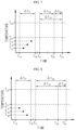
- FIGS. 3 and 4 are reference diagrams for illustrating operations of the temperature monitoring apparatus 200 according to an embodiment of the present disclosure.
- FIG. 3 exemplarily shows a case in which a temperature T 1A of the first battery module 110-1 measured by the first S-BMS 210-1 is lower than the first set temperature Tsi.
- the first S-BMS 210-1 switches to the wake-up mode at a wake-up time t 1A that is notified last by the M-BMS 220. That is, the first S-BMS 210-1 remains in the sleep mode until the wake-up time t 1A is reached from the last time point of switching to the sleep mode, and then, when the wake-up time t 1A set thereto in advance is reached, the first S-BMS 210-1 maintains in the wake-up mode during a predetermined maintaining time period ⁇ t p .
- the first S-BMS 210-1 switches to the sleep mode again when the maintaining time period ⁇ t p has passed from the wake-up time t 1A .
- a period from the latest wake-up time t 1A to a time point t 1B of switching to the sleep mode again may be referred to as a wake-up period. That is, the maintaining time period ⁇ t p denotes a time length of each wake-up period.
- the wake-up time of the second S-BMS 210-2 for measuring the temperature of the second battery module 110-2 may be delayed from the wake-up time of a case where the temperature T 1A of the first battery module 110-1 is equal to or higher than the first set temperature Tsi.
- the M-BMS 220 may set a time equivalent to a sum of a current time t C1 and a first set time period ⁇ t S1 as a next wake-up time t 2A of the second S-BMS 210-2. That is, the next wake-up time t 2A of the second S-BMS 210-2 is a time when the first set time period ⁇ t S1 passes from the current time tci.
- the current time t C1 is equal to the time t 1B or after the time tie.
- the second S-BMS 210-2 and the third S-BMS 210-3 may be in the sleep mode at least from the time t 1A to the time t 2A .
- FIG. 4 exemplarily shows a case in which the temperature T 1B of the first battery module 110-1 measured in the wake-up period by the first S-BMS 210-1 is equal to or higher than the first set temperature Tsi and lower than the second set temperature T S2 . That is, the temperature T 1B of the first battery module 110-1 is higher than the temperature T 1A in FIG. 3 .
- the M-BMS 220 may set a time equivalent to a sum of the current time t C1 and a second set time period ⁇ t S2 as a next wake-up time t 2A ' of the second S-BMS 210-2. That is, the next wake-up time t 2A ' of the second S-BMS 210-2 is a time when the second set time period ⁇ t S2 passes from the current time t C1 .
- the second set time period ⁇ t S2 is shorter than the first set time period ⁇ t S1 .
- the second S-BMS 210-2 may switch to the wake-up mode faster by a time period ⁇ t S1 - ⁇ t S2 than a case where the temperature T 1A of the first battery module 110-1 is lower than the first set temperature T S1 .
- the second S-BMS 210-2 and the third S-BMS 210-3 may be in the sleep mode at least from the time t 1A to the time t 2A' .
- FIGS. 5 and 6 are reference diagrams for illustrating operations of a temperature monitoring apparatus 200 according to another embodiment of the present disclosure.
- FIGS. 5 and 6 exemplarily show a case in which the second S-BMS 210-2 is switched to the wake-up mode at a wake-up time t 2A set by the M-BMS 220, like in FIG. 3 .
- the second S-BMS 210-2 may be switched to the sleep mode again at a time point t 2B when a maintaining time period ⁇ t p has passed from the wake-up time t 2A . That is, the second S-BMS 210-2 may operate in the wake-up mode during the maintaining time period ⁇ t p from the wake-up time t 2A .
- the second S-BMS 210-2 measures the temperature T 2A of the second battery module 110-2 and transmits second temperature data indicating the temperature of the second battery module 110-2 to the M-BMS 220.
- the temperature T 2A of the second battery module 110-2 may be equal to or higher than the first set temperature T S1 and lower than the second set temperature T S2 .
- the M-BMS 220 may set a time equivalent to a sum of a current time t C2 and a first set time period ⁇ t S1 as a next wake-up time of the third S-BMS 210-3, like the above-described manner with reference to FIG. 3 .
- the M-BMS 220 may set the next wake-up time of the third S-BMS 210-3 through a different calculation process.
- the M-BMS 220 may set a next wake-up time of the third S-BMS 210-3 further based on a result of comparing the temperature T 1A of the first battery module 110-1 with the temperature T 2A of the second battery module 110-2.
- the M-BMS 220 may calculate a difference value by subtracting the temperature T 2A of the second battery module 110-2 from the temperature T 1A of the first battery module 110-1, which is measured latest by the first S-BMS 210-1, that is, T 1A - T 2A .
- the difference value is a positive value, it denotes that the temperature T 2A of the second battery module 110-2 is lower than the temperature T 1A of the first battery module 110-1.
- the difference value is a negative value, it denotes that the temperature T 2A of the second battery module 110-2 is higher than the temperature T 1A of the first battery module 110-1.
- the difference value T 1A - T 2A would be a negative value.
- the temperature T 2A of the second battery module 110-2 that is measured after measuring the temperature T 1A of the first battery module 110-1 is higher than the temperature T 1A of the first battery module 110-1, it implies that the temperature of the battery pack 100 is increasing.
- the third S-BMS 210-3 is switched to the wake-up mode faster than a time equivalent to a sum of the current time t C2 and the first set time period ⁇ t S1 .
- the M-BMS 220 may set a time corresponding to the sum of the current time t C2 and a third set time period ⁇ t S3 as a next wake-up time of the third S-BMS 210-3.
- the third set time period ⁇ t S3 may be obtained by subtracting a compensation time period ⁇ t K1 from the first set time period ⁇ t S1 .
- the M-BMS 220 may determine the compensation time period ⁇ t K1 corresponding to the difference value T 1A - T 2A by using a predetermined algorithm, etc.
- the first S-BMS 210-1 and the third S-BMS 210-3 may be in the sleep mode at least from the time t 2A to the time t 3A .
- the M-BMS 220 may calculate a difference value by subtracting the temperature T 2B of the second battery module 110-2 from the temperature T 1A of the first battery module 110-1 that is measured latest by the first S-BMS 210-1, that is, T 1A - T 2B .
- the difference value T 1A - T 2B would be a positive value.
- the difference value T 1A - T 2B has a positive value, it implies that the battery pack 100 is being cooled down well. That is, a probability of overheating the battery pack 100 is relatively lowered.
- a time t 3A' equivalent to a sum of the current time t C2 and a fourth set time period ⁇ t S4 may be set as a next wake-up time of the third S-BMS 210-3.
- the fourth set time period ⁇ t S4 may be longer than the third set time period ⁇ t S3 .
- the fourth set time period ⁇ t S4 may be obtained by adding a compensation time period ⁇ t K2 with the first set time period ⁇ t S1 .
- the compensation time period ⁇ tK2 may have a time length corresponding to the difference value T 1A - T 2B .
- the M-BMS 220 may determine the compensation time period ⁇ t K2 corresponding to the difference value T 1A - T 2B by using a predetermined algorithm, etc.
- the first S-BMS 210-1 and the third S-BMS 210-3 may be in the sleep mode at least from the time t 2A to the time t 3A' .
- FIGS. 7 and 8 are reference diagrams for illustrating operations of a temperature monitoring apparatus 200 according to another embodiment of the present disclosure.
- the embodiment of FIG. 7 is different from that of FIG. 3 in that the temperature of the first battery module 110-1 is measured a plurality of times by the first S-BMS 210-1 during a single wake-up period, that is, from the time t 1A to the time t 1B .
- the first S-BMS 210-1 remains in the wake-up mode during the predetermined maintaining time period ⁇ t p from the wake-up time t 1A that is notified last by the M-BMS 220 and then switches to the sleep mode again.
- the present embodiment is different from the embodiment illustrated with reference to FIG.
- the first S-BMS 210-1 may transmit to the M-BMS 220 first temperature data including a plurality of temperature values of the first battery module 110-1 measured at the plurality of different time points within the single wake-up period.
- the M-BMS 220 may analyze a temperature variation pattern of the first battery module 110-1 during the wake-up period based on the first temperature data transmitted from the first S-BMS 210-1. For example, the M-BMS 220 may determine whether the temperature of the first battery module 110-1 increases or decreases according to time lapse.
- the M-BMS 220 may set a next wake-up time of the second S-BMS 210-2 based on the temperature of the first battery module 110-1 and the temperature variation pattern.
- the temperature of the first battery module 110-1 may gradually rise during the single wake-up period. That is, a temperature inclination of the first battery module 110-1 may have a positive value.
- a temperature inclination of the first battery module 110-1 may have a positive value.
- three temperature values of the first battery module 110-1 measured during the single wake-up period increase with a constant inclination so as to satisfy a condition T 1C ⁇ T ID ⁇ T 1E ⁇ T S1 .
- the M-BMS 220 may set a time t 2A " equivalent to a sum of the current time t C1 and a fifth set time period ⁇ t S5 as a next wake-up time of the second S-BMS 210-2.
- the compensation time ⁇ t K3 may have a time length corresponding to the temperature inclination of the first battery module 110-1 having a positive value.
- FIG. 8 exemplarily shows operations of the temperature monitoring apparatus 200 in a case where a temperature of the first battery module 110-1 gradually decreases during a single wake-up period.
- a temperature inclination of the first battery module 110-1 may have a negative value.
- three temperature values of the first battery module 110-1 measured during the single wake-up period decrease with a constant inclination so as to satisfy a condition T 1H ⁇ T 1G ⁇ T 1F ⁇ Tsi.
- the M-BMS 220 may set a time t 2A ′′′ equivalent to a sum of the current time t C1 and a sixth set time period ⁇ t S6 as a next wake-up time of the second S-BMS 210-2.
- the compensation time ⁇ t K4 may have a time length corresponding to the temperature inclination of the first battery module 110-1 having a negative value.
- FIGS. 7 and 8 illustrate that the M-BMS 220 of the temperature monitoring apparatus 200 sets a next wake-up time of the second S-BMS 210-2 according to a temperature variation pattern of the first battery module 110-1, but the same manner may be applied to another battery module.
- the M-BMS 220 may set a next wake-up time of the third S-BMS 210-3 according to a temperature variation pattern of the second battery module 110-2.
- the M-BMS 220 may set a next wake-up time of the first S-BMS 210-1 according to a temperature variation pattern of the third battery module 110-3.
- FIGS. 7 and 8 show the example in which the temperature of first battery module 110-1 is lower than the first set temperature T S1 , but the example may be also applied in a case where the temperature of first battery module 110-1 is equal to or higher than the first set temperature T S1 in a similar manner.
- FIG. 9 is a flowchart illustrating a method of monitoring a temperature of the battery pack 100, according to an embodiment of the present disclosure.
- step S910 the first S-BMS 210-1 switches from the sleep mode to the wake-up mode when a wake-up time set thereto by the M-BMS 220 is reached.
- step S920 is performed.
- the first S-BMS 210-1 measures a temperature of the first battery module 110-1 from among a plurality of battery modules included in the battery pack at least once during a wake-up period.
- the wake-up period may be defined as a period from the latest time point of switching to the wake-up mode to a time point of re-switching the sleep mode.
- the first S-BMS 210-1 transmits to the M-BMS 220 first temperature data indicating the temperature of the first battery module 110-1 measured during the wake-up period. After step S930, step S940 is performed.
- the M-BMS 220 sets a next wake-up time of the second S-BMS 210-2 based on the first temperature data transmitted from the first S-BMS 210-1 at step S930. For example, in a case where the temperature of the first battery module 110-1 corresponding to the first temperature data is lower than a first set temperature, the M-BMS 220 may set a time equivalent to a sum of the current time and a first set time period as a next wake-up time of the second S-BMS 210-2.
- the M-BMS 220 may set a time equivalent to a sum of the current time and a second set time period as a next wake-up time of the second S-BMS 210-2.
- the second set time period may be shorter than the first set time period.
- step S950 the second S-BMS 210-2 switches from the sleep mode to the wake-up mode when a wake-up time set thereto at step S940 by the M-BMS 220 is reached.
- step S960 is performed.
- the second S-BMS 210-2 measures a temperature of the second battery module 110-2 from among the plurality of battery modules, during the wake-up period that is defined as a period from the latest time point of switching to the wake-up mode to the time point of re-switching to the sleep mode. After step S960, step S970 is performed.
- the second S-BMS 210-2 transmits to the M-BMS 220 second temperature data indicating the temperature of the second battery module 110-2 measured during the wake-up period.
- the M-BMS 220 may set a next wake-up time of other S-BMSs than the second S-BMS 210-2, based on the second temperature data transmitted from the second S-BMS 210-2 at step S970.
- the above-described embodiments of the present disclosure are not embodied only by an apparatus and/or method.
- the above-described embodiments may be embodied by a program performing functions, which correspond to the configuration of the exemplary embodiments of the present disclosure, or a recording medium on which the program is recorded, and these embodiments may be easily devised from the description of the above embodiments by one of ordinary skill in the art to which the present invention pertains.
Landscapes
- Engineering & Computer Science (AREA)
- Chemical & Material Sciences (AREA)
- Chemical Kinetics & Catalysis (AREA)
- Electrochemistry (AREA)
- General Chemical & Material Sciences (AREA)
- Manufacturing & Machinery (AREA)
- Sustainable Development (AREA)
- Life Sciences & Earth Sciences (AREA)
- Sustainable Energy (AREA)
- Power Engineering (AREA)
- Transportation (AREA)
- Mechanical Engineering (AREA)
- Microelectronics & Electronic Packaging (AREA)
- Automation & Control Theory (AREA)
- Aviation & Aerospace Engineering (AREA)
- Secondary Cells (AREA)
- Electric Propulsion And Braking For Vehicles (AREA)
- Arrangement Or Mounting Of Propulsion Units For Vehicles (AREA)
Applications Claiming Priority (2)
| Application Number | Priority Date | Filing Date | Title |
|---|---|---|---|
| KR1020160102925A KR102046608B1 (ko) | 2016-08-12 | 2016-08-12 | 배터리 팩을 위한 온도 모니터링 장치 및 방법 |
| PCT/KR2017/008355 WO2018030704A1 (ko) | 2016-08-12 | 2017-08-02 | 배터리 팩을 위한 온도 모니터링 장치 및 방법 |
Publications (3)
| Publication Number | Publication Date |
|---|---|
| EP3376588A1 EP3376588A1 (en) | 2018-09-19 |
| EP3376588A4 EP3376588A4 (en) | 2019-01-02 |
| EP3376588B1 true EP3376588B1 (en) | 2023-10-04 |
Family
ID=61162337
Family Applications (1)
| Application Number | Title | Priority Date | Filing Date |
|---|---|---|---|
| EP17839722.0A Active EP3376588B1 (en) | 2016-08-12 | 2017-08-02 | Temperature monitoring apparatus and method for battery pack |
Country Status (6)
| Country | Link |
|---|---|
| US (1) | US10991994B2 (ko) |
| EP (1) | EP3376588B1 (ko) |
| JP (1) | JP6580790B2 (ko) |
| KR (1) | KR102046608B1 (ko) |
| CN (1) | CN108432030B (ko) |
| WO (1) | WO2018030704A1 (ko) |
Families Citing this family (25)
| Publication number | Priority date | Publication date | Assignee | Title |
|---|---|---|---|---|
| KR102204301B1 (ko) * | 2017-07-20 | 2021-01-15 | 주식회사 엘지화학 | 무선 배터리 관리 시스템 및 이를 포함하는 배터리팩 |
| US11260762B2 (en) * | 2018-04-30 | 2022-03-01 | Ford Global Technologies, Llc | Auxiliary battery charging systems and methods for electrified vehicles |
| CN117996236A (zh) | 2018-07-27 | 2024-05-07 | 奥动新能源汽车科技有限公司 | 智能电池箱及检测方法 |
| CN111044912B (zh) * | 2018-10-12 | 2021-10-01 | 宁德时代新能源科技股份有限公司 | 休眠监测系统和方法 |
| KR102029422B1 (ko) | 2018-10-16 | 2019-10-07 | 주식회사 담우광학전자기술 | 배터리팩 온도검출용 센서유닛 및 이를 구비한 에너지저장시스템의 배터리팩 모니터링 장치 |
| US10481623B1 (en) * | 2018-12-17 | 2019-11-19 | Chongqing Jinkang New Energy Automobile Co., Ltd. | Optimizing a temperature profile in a thermal management system of an electric vehicle |
| KR20210016797A (ko) | 2019-08-05 | 2021-02-17 | 주식회사 엘지화학 | 배터리의 성능 예측 장치 및 애플리케이션 |
| CN110481383B (zh) * | 2019-08-29 | 2020-10-23 | 华人运通(江苏)技术有限公司 | 基于电池管理系统的数据处理方法及电池管理系统 |
| KR102640095B1 (ko) * | 2019-09-09 | 2024-02-26 | 주식회사 엘지에너지솔루션 | 절전형 배터리 관리 장치 및 방법 |
| CN112874303B (zh) * | 2019-11-29 | 2022-09-13 | 中车时代电动汽车股份有限公司 | 一种新能源汽车安全监控方法 |
| CN111537901B (zh) * | 2020-04-09 | 2022-06-17 | 浙江南都电源动力股份有限公司 | 一种电池电量状态测算方法、电池组以及交通工具 |
| CN113933719A (zh) * | 2020-06-29 | 2022-01-14 | 比亚迪股份有限公司 | 监测电芯故障的系统、方法及车辆 |
| CN112319305A (zh) * | 2020-10-10 | 2021-02-05 | 蔚来汽车科技(安徽)有限公司 | 车辆的安全监控方法、监控系统和装置 |
| EP4099474A4 (en) * | 2020-11-03 | 2024-01-10 | LG Energy Solution, Ltd. | BATTERY RACK MANAGEMENT DEVICE |
| DE102021001217A1 (de) * | 2021-03-08 | 2022-09-08 | Mercedes-Benz Group AG | Verfahren zur Überwachung eines Batteriesystems |
| US20220329358A1 (en) * | 2021-04-07 | 2022-10-13 | Marvell Asia Pte Ltd | Automatic resending of wup by slave device |
| KR20220167988A (ko) * | 2021-06-15 | 2022-12-22 | 주식회사 엘지에너지솔루션 | 마이크로 컨트롤러의 온도 측정을 위한 배터리 관리장치의 구성 및 그 제어방법 |
| CN113978311B (zh) * | 2021-10-15 | 2024-05-17 | 潍柴动力股份有限公司 | 一种电池温度修正方法、装置及电子设备 |
| DE102021133462A1 (de) * | 2021-12-16 | 2023-06-22 | Webasto SE | Batterie und Batteriesteuerungsverfahren |
| FR3131565A1 (fr) * | 2022-01-03 | 2023-07-07 | Psa Automobiles Sa | Contrôle de la température interne d’une batterie principale dans un véhicule endormi |
| CN114559819B (zh) * | 2022-01-25 | 2023-10-13 | 重庆标能瑞源储能技术研究院有限公司 | 一种基于信号处理的电动汽车电池安全预警方法 |
| CN114844191B (zh) * | 2022-04-21 | 2024-08-13 | 中国第一汽车股份有限公司 | 智能补电方法、装置、存储介质及电子装置 |
| US11584254B1 (en) | 2022-04-29 | 2023-02-21 | Beta Air, Llc | System and method for energy tracking in an electric aircraft |
| KR20240020590A (ko) * | 2022-08-08 | 2024-02-15 | 주식회사 엘지에너지솔루션 | 배터리 화재 예측 방법 및 그 방법을 제공하는 배터리 시스템 |
| KR20240101170A (ko) * | 2022-12-23 | 2024-07-02 | 주식회사 엘지에너지솔루션 | 배터리의 출력 예측 방법 및 그 방법을 제공하는 배터리 시스템 |
Family Cites Families (24)
| Publication number | Priority date | Publication date | Assignee | Title |
|---|---|---|---|---|
| JP3939546B2 (ja) * | 2001-12-06 | 2007-07-04 | パナソニック・イーブイ・エナジー株式会社 | 電動車両の電池電源装置 |
| JP4929597B2 (ja) * | 2005-01-31 | 2012-05-09 | トヨタ自動車株式会社 | 電池モジュールの暖機装置 |
| KR100680901B1 (ko) | 2006-02-28 | 2007-02-09 | 김금수 | 배터리 관리 시스템 및 그 제어 방법 |
| JP4432985B2 (ja) | 2007-03-12 | 2010-03-17 | ソニー株式会社 | 電池パック |
| JP5699702B2 (ja) * | 2011-03-11 | 2015-04-15 | 日産自動車株式会社 | 車両の充電制御装置 |
| JP5708070B2 (ja) * | 2011-03-11 | 2015-04-30 | 日産自動車株式会社 | バッテリ温度制御装置 |
| JP5720322B2 (ja) * | 2011-03-11 | 2015-05-20 | 日産自動車株式会社 | バッテリ温度制御装置 |
| KR101245285B1 (ko) | 2011-04-15 | 2013-03-19 | 주식회사 엘지화학 | 배터리 모듈의 온도 감지장치 및 배터리 팩 관리장치와 방법 |
| KR101264020B1 (ko) * | 2011-05-16 | 2013-05-14 | 삼성전기주식회사 | 에너지 저장 시스템 및 에너지 저장 시스템 제어방법 |
| KR101300109B1 (ko) * | 2011-05-31 | 2013-09-02 | 주식회사 엘지화학 | 모듈화된 bms 연결 구조를 포함하는 전력 저장 시스템 및 그 제어 방법 |
| EP2717423B1 (en) | 2011-05-31 | 2020-01-22 | LG Chem, Ltd. | Power storage system having modularized bms connection structure and method for controlling the system |
| WO2013005286A1 (ja) * | 2011-07-04 | 2013-01-10 | 三菱電機株式会社 | 温度監視装置および温度監視方法 |
| WO2013079983A1 (en) * | 2011-12-02 | 2013-06-06 | Rimac Automobili D.O.O. | System and process for mantaining of working temeperature of battery cells for starter accumulators in vehicles |
| JP6040684B2 (ja) * | 2012-09-28 | 2016-12-07 | 富士通株式会社 | 二次電池の状態評価装置、二次電池の状態評価方法、及び、二次電池の状態評価プログラム |
| KR101768251B1 (ko) * | 2013-04-05 | 2017-08-30 | 삼성에스디아이 주식회사 | 배터리 모듈의 정상 연결 상태 확인을 제공하는 배터리 팩 |
| KR20150071194A (ko) * | 2013-12-18 | 2015-06-26 | 현대자동차주식회사 | 자동차용 배터리 모듈간 온도 밸런싱 제어 시스템 |
| JP6090265B2 (ja) | 2014-08-29 | 2017-03-08 | トヨタ自動車株式会社 | 車両 |
| WO2016047095A1 (ja) * | 2014-09-26 | 2016-03-31 | パナソニックIpマネジメント株式会社 | 電源装置 |
| JP6471463B2 (ja) * | 2014-11-06 | 2019-02-20 | 日立化成株式会社 | 蓄電池状態監視システム、蓄電池状態監視方法、および蓄電池状態監視プログラム |
| JP6392088B2 (ja) * | 2014-11-13 | 2018-09-19 | 株式会社日立製作所 | 無線電池システム並びにこれに用いるセルコントローラ及びバッテリコントローラ |
| KR101826895B1 (ko) * | 2014-12-23 | 2018-02-07 | 주식회사 엘지화학 | 모듈 내외부로 인출입이 가능하며 모듈 내부에서 온도 센서의 고정력이 강화된 구조를 갖는 배터리 모듈 및 이를 포함하는 배터리 팩 |
| KR102357351B1 (ko) * | 2015-01-07 | 2022-01-28 | 삼성전자주식회사 | 복수의 배터리 셀들을 포함하는 배터리 팩의 상태를 추정하는 장치 및 방법 |
| JP6759200B2 (ja) * | 2015-07-06 | 2020-09-23 | 三洋電機株式会社 | 電池パック及び二次電池の放電制御方法 |
| US9931956B2 (en) * | 2015-12-30 | 2018-04-03 | Thunder Power New Energy Vehicle Development Company Limited | Battery management system |
-
2016
- 2016-08-12 KR KR1020160102925A patent/KR102046608B1/ko active IP Right Grant
-
2017
- 2017-08-02 CN CN201780005222.4A patent/CN108432030B/zh active Active
- 2017-08-02 US US16/060,829 patent/US10991994B2/en active Active
- 2017-08-02 WO PCT/KR2017/008355 patent/WO2018030704A1/ko active Application Filing
- 2017-08-02 JP JP2018533791A patent/JP6580790B2/ja active Active
- 2017-08-02 EP EP17839722.0A patent/EP3376588B1/en active Active
Also Published As
| Publication number | Publication date |
|---|---|
| CN108432030A (zh) | 2018-08-21 |
| EP3376588A1 (en) | 2018-09-19 |
| KR20180018040A (ko) | 2018-02-21 |
| WO2018030704A1 (ko) | 2018-02-15 |
| CN108432030B (zh) | 2021-02-12 |
| EP3376588A4 (en) | 2019-01-02 |
| US20190006724A1 (en) | 2019-01-03 |
| US10991994B2 (en) | 2021-04-27 |
| JP6580790B2 (ja) | 2019-09-25 |
| KR102046608B1 (ko) | 2019-11-19 |
| JP2019504450A (ja) | 2019-02-14 |
Similar Documents
| Publication | Publication Date | Title |
|---|---|---|
| EP3376588B1 (en) | Temperature monitoring apparatus and method for battery pack | |
| EP3540844B1 (en) | Battery management aparatus and battery pack including same | |
| KR101998069B1 (ko) | 전기자동차용 배터리의 열화 발생을 저감하면서 고속충전과 최대방전을 수행하기 위한 방법 및 그 장치 | |
| KR102014451B1 (ko) | 이차 전지의 출력 파라미터를 조정하는 시스템 및 그 방법 | |
| EP3252918B1 (en) | Apparatus and method for adjusting charging condition of secondary battery | |
| CN106469927B (zh) | 基于电压的电池热状态的早期警告 | |
| KR101648893B1 (ko) | 배터리 팩 및 이의 제어방법 | |
| EP2769872B1 (en) | Hybrid battery system for an electric vehicle | |
| EP2908378B1 (en) | Battery system with selective thermal management group | |
| KR101813461B1 (ko) | 배터리 관리 시스템 내의 데이터 전송 방법 | |
| JP2015522899A5 (ko) | ||
| CN202616826U (zh) | 电池的主动平衡测试装置 | |
| CN108666713A (zh) | 用于双车加热的电池组加热装置与控制方法 | |
| KR20210048319A (ko) | 차량용 배터리 시스템 및 그 제어방법 | |
| CN105048010A (zh) | 一种电动汽车电池包的监控方法及系统 | |
| CN113412208B (zh) | 用于管理车辆的能量储存系统的方法 | |
| KR101741303B1 (ko) | 배터리 랙 간 전압 밸런싱 장치 및 방법 | |
| EP3974850A1 (en) | Parallel battery relay diagnosis device and method | |
| EP4002553A1 (en) | Battery temperature control apparatus, battery system, energy storage system and battery temperature control method | |
| JP2017118741A (ja) | 制御装置 | |
| US20190312314A1 (en) | System and method for storing a battery | |
| Buretea et al. | Hybrid car battery management | |
| KR20200025496A (ko) | 알람 설정 장치 |
Legal Events
| Date | Code | Title | Description |
|---|---|---|---|
| STAA | Information on the status of an ep patent application or granted ep patent |
Free format text: STATUS: THE INTERNATIONAL PUBLICATION HAS BEEN MADE |
|
| PUAI | Public reference made under article 153(3) epc to a published international application that has entered the european phase |
Free format text: ORIGINAL CODE: 0009012 |
|
| STAA | Information on the status of an ep patent application or granted ep patent |
Free format text: STATUS: REQUEST FOR EXAMINATION WAS MADE |
|
| 17P | Request for examination filed |
Effective date: 20180613 |
|
| AK | Designated contracting states |
Kind code of ref document: A1 Designated state(s): AL AT BE BG CH CY CZ DE DK EE ES FI FR GB GR HR HU IE IS IT LI LT LU LV MC MK MT NL NO PL PT RO RS SE SI SK SM TR |
|
| AX | Request for extension of the european patent |
Extension state: BA ME |
|
| A4 | Supplementary search report drawn up and despatched |
Effective date: 20181204 |
|
| RIC1 | Information provided on ipc code assigned before grant |
Ipc: H01M 10/42 20060101ALI20181128BHEP Ipc: H01M 10/633 20140101ALI20181128BHEP Ipc: H01M 10/48 20060101AFI20181128BHEP Ipc: B60L 11/18 20060101ALI20181128BHEP Ipc: H01M 2/10 20060101ALI20181128BHEP |
|
| DAV | Request for validation of the european patent (deleted) | ||
| DAX | Request for extension of the european patent (deleted) | ||
| RAP1 | Party data changed (applicant data changed or rights of an application transferred) |
Owner name: LG ENERGY SOLUTION LTD. |
|
| RAP3 | Party data changed (applicant data changed or rights of an application transferred) |
Owner name: LG ENERGY SOLUTION, LTD. |
|
| REG | Reference to a national code |
Ref country code: DE Ref legal event code: R079 Ref document number: 602017074992 Country of ref document: DE Free format text: PREVIOUS MAIN CLASS: H01M0010480000 Ipc: H01M0010420000 Free format text: PREVIOUS MAIN CLASS: H01M0010480000 |
|
| GRAP | Despatch of communication of intention to grant a patent |
Free format text: ORIGINAL CODE: EPIDOSNIGR1 |
|
| STAA | Information on the status of an ep patent application or granted ep patent |
Free format text: STATUS: GRANT OF PATENT IS INTENDED |
|
| INTG | Intention to grant announced |
Effective date: 20230519 |
|
| RIC1 | Information provided on ipc code assigned before grant |
Ipc: B60L 58/21 20190101ALI20230505BHEP Ipc: B60L 58/24 20190101ALI20230505BHEP Ipc: B60L 58/12 20190101ALI20230505BHEP Ipc: B60L 58/10 20190101ALI20230505BHEP Ipc: H01M 10/48 20060101ALI20230505BHEP Ipc: H01M 10/633 20140101ALI20230505BHEP Ipc: H01M 10/42 20060101AFI20230505BHEP |
|
| GRAS | Grant fee paid |
Free format text: ORIGINAL CODE: EPIDOSNIGR3 |
|
| P01 | Opt-out of the competence of the unified patent court (upc) registered |
Effective date: 20230530 |
|
| GRAA | (expected) grant |
Free format text: ORIGINAL CODE: 0009210 |
|
| STAA | Information on the status of an ep patent application or granted ep patent |
Free format text: STATUS: THE PATENT HAS BEEN GRANTED |
|
| AK | Designated contracting states |
Kind code of ref document: B1 Designated state(s): AL AT BE BG CH CY CZ DE DK EE ES FI FR GB GR HR HU IE IS IT LI LT LU LV MC MK MT NL NO PL PT RO RS SE SI SK SM TR |
|
| REG | Reference to a national code |
Ref country code: GB Ref legal event code: FG4D |
|
| REG | Reference to a national code |
Ref country code: CH Ref legal event code: EP |
|
| REG | Reference to a national code |
Ref country code: IE Ref legal event code: FG4D |
|
| REG | Reference to a national code |
Ref country code: DE Ref legal event code: R096 Ref document number: 602017074992 Country of ref document: DE |
|
| REG | Reference to a national code |
Ref country code: LT Ref legal event code: MG9D |
|
| REG | Reference to a national code |
Ref country code: NL Ref legal event code: MP Effective date: 20231004 |
|
| REG | Reference to a national code |
Ref country code: AT Ref legal event code: MK05 Ref document number: 1618684 Country of ref document: AT Kind code of ref document: T Effective date: 20231004 |
|
| PG25 | Lapsed in a contracting state [announced via postgrant information from national office to epo] |
Ref country code: NL Free format text: LAPSE BECAUSE OF FAILURE TO SUBMIT A TRANSLATION OF THE DESCRIPTION OR TO PAY THE FEE WITHIN THE PRESCRIBED TIME-LIMIT Effective date: 20231004 |
|
| PG25 | Lapsed in a contracting state [announced via postgrant information from national office to epo] |
Ref country code: GR Free format text: LAPSE BECAUSE OF FAILURE TO SUBMIT A TRANSLATION OF THE DESCRIPTION OR TO PAY THE FEE WITHIN THE PRESCRIBED TIME-LIMIT Effective date: 20240105 |
|
| PG25 | Lapsed in a contracting state [announced via postgrant information from national office to epo] |
Ref country code: IS Free format text: LAPSE BECAUSE OF FAILURE TO SUBMIT A TRANSLATION OF THE DESCRIPTION OR TO PAY THE FEE WITHIN THE PRESCRIBED TIME-LIMIT Effective date: 20240204 |
|
| PG25 | Lapsed in a contracting state [announced via postgrant information from national office to epo] |
Ref country code: LT Free format text: LAPSE BECAUSE OF FAILURE TO SUBMIT A TRANSLATION OF THE DESCRIPTION OR TO PAY THE FEE WITHIN THE PRESCRIBED TIME-LIMIT Effective date: 20231004 |
|
| PG25 | Lapsed in a contracting state [announced via postgrant information from national office to epo] |
Ref country code: AT Free format text: LAPSE BECAUSE OF FAILURE TO SUBMIT A TRANSLATION OF THE DESCRIPTION OR TO PAY THE FEE WITHIN THE PRESCRIBED TIME-LIMIT Effective date: 20231004 |
|
| PG25 | Lapsed in a contracting state [announced via postgrant information from national office to epo] |
Ref country code: ES Free format text: LAPSE BECAUSE OF FAILURE TO SUBMIT A TRANSLATION OF THE DESCRIPTION OR TO PAY THE FEE WITHIN THE PRESCRIBED TIME-LIMIT Effective date: 20231004 |
|
| PG25 | Lapsed in a contracting state [announced via postgrant information from national office to epo] |
Ref country code: LT Free format text: LAPSE BECAUSE OF FAILURE TO SUBMIT A TRANSLATION OF THE DESCRIPTION OR TO PAY THE FEE WITHIN THE PRESCRIBED TIME-LIMIT Effective date: 20231004 Ref country code: IS Free format text: LAPSE BECAUSE OF FAILURE TO SUBMIT A TRANSLATION OF THE DESCRIPTION OR TO PAY THE FEE WITHIN THE PRESCRIBED TIME-LIMIT Effective date: 20240204 Ref country code: GR Free format text: LAPSE BECAUSE OF FAILURE TO SUBMIT A TRANSLATION OF THE DESCRIPTION OR TO PAY THE FEE WITHIN THE PRESCRIBED TIME-LIMIT Effective date: 20240105 Ref country code: ES Free format text: LAPSE BECAUSE OF FAILURE TO SUBMIT A TRANSLATION OF THE DESCRIPTION OR TO PAY THE FEE WITHIN THE PRESCRIBED TIME-LIMIT Effective date: 20231004 Ref country code: BG Free format text: LAPSE BECAUSE OF FAILURE TO SUBMIT A TRANSLATION OF THE DESCRIPTION OR TO PAY THE FEE WITHIN THE PRESCRIBED TIME-LIMIT Effective date: 20240104 Ref country code: AT Free format text: LAPSE BECAUSE OF FAILURE TO SUBMIT A TRANSLATION OF THE DESCRIPTION OR TO PAY THE FEE WITHIN THE PRESCRIBED TIME-LIMIT Effective date: 20231004 Ref country code: PT Free format text: LAPSE BECAUSE OF FAILURE TO SUBMIT A TRANSLATION OF THE DESCRIPTION OR TO PAY THE FEE WITHIN THE PRESCRIBED TIME-LIMIT Effective date: 20240205 |
|
| PG25 | Lapsed in a contracting state [announced via postgrant information from national office to epo] |
Ref country code: SE Free format text: LAPSE BECAUSE OF FAILURE TO SUBMIT A TRANSLATION OF THE DESCRIPTION OR TO PAY THE FEE WITHIN THE PRESCRIBED TIME-LIMIT Effective date: 20231004 Ref country code: RS Free format text: LAPSE BECAUSE OF FAILURE TO SUBMIT A TRANSLATION OF THE DESCRIPTION OR TO PAY THE FEE WITHIN THE PRESCRIBED TIME-LIMIT Effective date: 20231004 Ref country code: PL Free format text: LAPSE BECAUSE OF FAILURE TO SUBMIT A TRANSLATION OF THE DESCRIPTION OR TO PAY THE FEE WITHIN THE PRESCRIBED TIME-LIMIT Effective date: 20231004 Ref country code: NO Free format text: LAPSE BECAUSE OF FAILURE TO SUBMIT A TRANSLATION OF THE DESCRIPTION OR TO PAY THE FEE WITHIN THE PRESCRIBED TIME-LIMIT Effective date: 20240104 Ref country code: LV Free format text: LAPSE BECAUSE OF FAILURE TO SUBMIT A TRANSLATION OF THE DESCRIPTION OR TO PAY THE FEE WITHIN THE PRESCRIBED TIME-LIMIT Effective date: 20231004 Ref country code: HR Free format text: LAPSE BECAUSE OF FAILURE TO SUBMIT A TRANSLATION OF THE DESCRIPTION OR TO PAY THE FEE WITHIN THE PRESCRIBED TIME-LIMIT Effective date: 20231004 |
|
| REG | Reference to a national code |
Ref country code: DE Ref legal event code: R097 Ref document number: 602017074992 Country of ref document: DE |
|
| PG25 | Lapsed in a contracting state [announced via postgrant information from national office to epo] |
Ref country code: DK Free format text: LAPSE BECAUSE OF FAILURE TO SUBMIT A TRANSLATION OF THE DESCRIPTION OR TO PAY THE FEE WITHIN THE PRESCRIBED TIME-LIMIT Effective date: 20231004 |
|
| PG25 | Lapsed in a contracting state [announced via postgrant information from national office to epo] |
Ref country code: CZ Free format text: LAPSE BECAUSE OF FAILURE TO SUBMIT A TRANSLATION OF THE DESCRIPTION OR TO PAY THE FEE WITHIN THE PRESCRIBED TIME-LIMIT Effective date: 20231004 |
|
| PG25 | Lapsed in a contracting state [announced via postgrant information from national office to epo] |
Ref country code: SK Free format text: LAPSE BECAUSE OF FAILURE TO SUBMIT A TRANSLATION OF THE DESCRIPTION OR TO PAY THE FEE WITHIN THE PRESCRIBED TIME-LIMIT Effective date: 20231004 |
|
| PG25 | Lapsed in a contracting state [announced via postgrant information from national office to epo] |
Ref country code: SM Free format text: LAPSE BECAUSE OF FAILURE TO SUBMIT A TRANSLATION OF THE DESCRIPTION OR TO PAY THE FEE WITHIN THE PRESCRIBED TIME-LIMIT Effective date: 20231004 Ref country code: SK Free format text: LAPSE BECAUSE OF FAILURE TO SUBMIT A TRANSLATION OF THE DESCRIPTION OR TO PAY THE FEE WITHIN THE PRESCRIBED TIME-LIMIT Effective date: 20231004 Ref country code: RO Free format text: LAPSE BECAUSE OF FAILURE TO SUBMIT A TRANSLATION OF THE DESCRIPTION OR TO PAY THE FEE WITHIN THE PRESCRIBED TIME-LIMIT Effective date: 20231004 Ref country code: IT Free format text: LAPSE BECAUSE OF FAILURE TO SUBMIT A TRANSLATION OF THE DESCRIPTION OR TO PAY THE FEE WITHIN THE PRESCRIBED TIME-LIMIT Effective date: 20231004 Ref country code: EE Free format text: LAPSE BECAUSE OF FAILURE TO SUBMIT A TRANSLATION OF THE DESCRIPTION OR TO PAY THE FEE WITHIN THE PRESCRIBED TIME-LIMIT Effective date: 20231004 Ref country code: DK Free format text: LAPSE BECAUSE OF FAILURE TO SUBMIT A TRANSLATION OF THE DESCRIPTION OR TO PAY THE FEE WITHIN THE PRESCRIBED TIME-LIMIT Effective date: 20231004 Ref country code: CZ Free format text: LAPSE BECAUSE OF FAILURE TO SUBMIT A TRANSLATION OF THE DESCRIPTION OR TO PAY THE FEE WITHIN THE PRESCRIBED TIME-LIMIT Effective date: 20231004 |
|
| PLBE | No opposition filed within time limit |
Free format text: ORIGINAL CODE: 0009261 |
|
| STAA | Information on the status of an ep patent application or granted ep patent |
Free format text: STATUS: NO OPPOSITION FILED WITHIN TIME LIMIT |
|
| 26N | No opposition filed |
Effective date: 20240705 |