EP3376439B1 - Method, apparatus for image analyzation, and non-transitory computer-readable storage medium - Google Patents
Method, apparatus for image analyzation, and non-transitory computer-readable storage medium Download PDFInfo
- Publication number
- EP3376439B1 EP3376439B1 EP18156661.3A EP18156661A EP3376439B1 EP 3376439 B1 EP3376439 B1 EP 3376439B1 EP 18156661 A EP18156661 A EP 18156661A EP 3376439 B1 EP3376439 B1 EP 3376439B1
- Authority
- EP
- European Patent Office
- Prior art keywords
- range
- image
- area
- saturation
- computer
- Prior art date
- Legal status (The legal status is an assumption and is not a legal conclusion. Google has not performed a legal analysis and makes no representation as to the accuracy of the status listed.)
- Active
Links
- 238000000034 method Methods 0.000 title claims description 34
- 238000001514 detection method Methods 0.000 claims description 26
- 241001465754 Metazoa Species 0.000 claims description 10
- 238000003384 imaging method Methods 0.000 claims description 2
- 238000010191 image analysis Methods 0.000 claims 2
- 238000004458 analytical method Methods 0.000 description 57
- 238000012544 monitoring process Methods 0.000 description 39
- 241000283690 Bos taurus Species 0.000 description 12
- 238000010586 diagram Methods 0.000 description 12
- 238000004891 communication Methods 0.000 description 7
- 230000006870 function Effects 0.000 description 5
- 230000011218 segmentation Effects 0.000 description 4
- 230000035606 childbirth Effects 0.000 description 3
- 230000001747 exhibiting effect Effects 0.000 description 3
- 235000013365 dairy product Nutrition 0.000 description 2
- 230000000694 effects Effects 0.000 description 2
- 230000001419 dependent effect Effects 0.000 description 1
- 238000005516 engineering process Methods 0.000 description 1
- 230000007613 environmental effect Effects 0.000 description 1
- 230000005484 gravity Effects 0.000 description 1
- 239000004973 liquid crystal related substance Substances 0.000 description 1
- 239000003550 marker Substances 0.000 description 1
- 239000008267 milk Substances 0.000 description 1
- 235000013336 milk Nutrition 0.000 description 1
- 210000004080 milk Anatomy 0.000 description 1
- 239000004065 semiconductor Substances 0.000 description 1
- 230000003068 static effect Effects 0.000 description 1
- 208000002254 stillbirth Diseases 0.000 description 1
- 231100000537 stillbirth Toxicity 0.000 description 1
Images


Classifications
-
- A—HUMAN NECESSITIES
- A61—MEDICAL OR VETERINARY SCIENCE; HYGIENE
- A61D—VETERINARY INSTRUMENTS, IMPLEMENTS, TOOLS, OR METHODS
- A61D17/00—Devices for indicating trouble during labour of animals ; Methods or instruments for detecting pregnancy-related states of animals
- A61D17/008—Devices for indicating trouble during labour of animals ; Methods or instruments for detecting pregnancy-related states of animals for detecting birth of animals, e.g. parturition alarm
-
- G06T5/90—
-
- G—PHYSICS
- G06—COMPUTING; CALCULATING OR COUNTING
- G06T—IMAGE DATA PROCESSING OR GENERATION, IN GENERAL
- G06T7/00—Image analysis
- G06T7/90—Determination of colour characteristics
-
- G—PHYSICS
- G06—COMPUTING; CALCULATING OR COUNTING
- G06V—IMAGE OR VIDEO RECOGNITION OR UNDERSTANDING
- G06V10/00—Arrangements for image or video recognition or understanding
- G06V10/20—Image preprocessing
- G06V10/22—Image preprocessing by selection of a specific region containing or referencing a pattern; Locating or processing of specific regions to guide the detection or recognition
- G06V10/235—Image preprocessing by selection of a specific region containing or referencing a pattern; Locating or processing of specific regions to guide the detection or recognition based on user input or interaction
-
- G—PHYSICS
- G06—COMPUTING; CALCULATING OR COUNTING
- G06V—IMAGE OR VIDEO RECOGNITION OR UNDERSTANDING
- G06V20/00—Scenes; Scene-specific elements
- G06V20/40—Scenes; Scene-specific elements in video content
- G06V20/46—Extracting features or characteristics from the video content, e.g. video fingerprints, representative shots or key frames
-
- G—PHYSICS
- G06—COMPUTING; CALCULATING OR COUNTING
- G06V—IMAGE OR VIDEO RECOGNITION OR UNDERSTANDING
- G06V20/00—Scenes; Scene-specific elements
- G06V20/50—Context or environment of the image
- G06V20/52—Surveillance or monitoring of activities, e.g. for recognising suspicious objects
-
- G—PHYSICS
- G06—COMPUTING; CALCULATING OR COUNTING
- G06T—IMAGE DATA PROCESSING OR GENERATION, IN GENERAL
- G06T2207/00—Indexing scheme for image analysis or image enhancement
- G06T2207/10—Image acquisition modality
- G06T2207/10024—Color image
-
- G—PHYSICS
- G06—COMPUTING; CALCULATING OR COUNTING
- G06T—IMAGE DATA PROCESSING OR GENERATION, IN GENERAL
- G06T2207/00—Indexing scheme for image analysis or image enhancement
- G06T2207/20—Special algorithmic details
- G06T2207/20004—Adaptive image processing
- G06T2207/20008—Globally adaptive
-
- G—PHYSICS
- G06—COMPUTING; CALCULATING OR COUNTING
- G06T—IMAGE DATA PROCESSING OR GENERATION, IN GENERAL
- G06T2207/00—Indexing scheme for image analysis or image enhancement
- G06T2207/30—Subject of image; Context of image processing
- G06T2207/30108—Industrial image inspection
-
- G—PHYSICS
- G06—COMPUTING; CALCULATING OR COUNTING
- G06T—IMAGE DATA PROCESSING OR GENERATION, IN GENERAL
- G06T7/00—Image analysis
- G06T7/20—Analysis of motion
Definitions
- the embodiment discussed herein is related to a method, an apparatus for image analyzation, and a non-transitory computer-readable storage medium.
- the accuracy of analyzing images undesirably tends to be low since the technique proposed in the related art attempts to detect a target from image information in accordance with a static pattern.
- a target e.g., a collar worn by a subject animal
- an image capture environment such as time of a day, lighting conditions, and the like
- the color saturation of the target to be extracted from the image information may not matches with a supposed condition regarding the color saturation of the target, and then the collar worn by the subject animal may not be detected correctly from the image information.
- the collar worn by the subject animal is merely one example of a target to be detected from an image captured by an imaging device. The problem mentioned above may arise even when a target object, which is other than a collar, is attached to a subject animal.
- the accuracy of analyzing images improves.
- FIG. 1 is a diagram illustrating an example of a system according to the present embodiment. As illustrated in FIG. 1 , the system includes a camera 10 and an analysis apparatus 100. The camera 10 and the analysis apparatus 100 are connected to each other through a network 50.
- the camera 10 is installed in an intended place such as a cowshed 1.
- a cow 5 with a collar 5a in a certain color is bred and farmed.
- An image capture range of the camera 10 includes an area in the cowshed 1 in which the cow 5 can move.
- the camera 10 transmits information regarding a captured image to the analysis apparatus 100.
- the information regarding a captured image is information regarding a plurality of successive image frames. In the following description, image frames will also be referred to as "monitoring images”.
- the analysis apparatus 100 analyzes monitoring images transmitted from the camera 10 to identify coordinates of the collar 5a in the monitoring images and calculate the amount of movement of the cow 5.
- the analysis apparatus 100 determines whether an environment in which the monitoring image has been captured conforms with a first image capture environment (e.g., at night) and a second image capture environment (e.g., a fluorescent light 6 is on). If the environment in which the monitoring image has been captured conforms with both of the first image capture environment (e.g., at night) and the second image capture environment (e.g., the fluorescent light 6 is on), the analysis apparatus 100 extends a range of color saturation in detection parameters for detecting the collar 5a.
- a first image capture environment e.g., at night
- a second image capture environment e.g., a fluorescent light 6 is on
- the collar 5a can be detected even if the color saturation of the collar 5a in the monitoring image is low due to the image capture environment (e.g., at night and the fluorescent light 6 is on). Analysis accuracy, therefore, may be improved even when the color saturation of the target object to be extracted from the image information is varied due to the image capture environment. As a result, the accuracy of detecting a target in monitoring images is improved, and the amount of movement of a subject (e.g., a cow) can be accurately estimated based on changes in a position of the target (e.g., a collar) detected from the monitoring images.
- a subject e.g., a cow
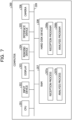
- FIG. 2 is a functional block diagram illustrating the configuration of the analysis apparatus 100 according to the present embodiment.
- the analysis apparatus 100 includes a communication unit 110, an input unit 120, a display unit 130, a storage unit 140, and a control unit 150.
- the communication unit 110 is a processing unit that communicates data with the camera 10 illustrated in FIG. 1 through the network 50.
- the control unit 150 which will be described later, receives information regarding images of the cowshed 1 from the camera 10 through the communication unit 110.
- the communication unit 110 may communicate with another external apparatus through the network 50.
- the communication unit 110 corresponds to a communication device.
- the input unit 120 is an input device for inputting various pieces of information to the analysis apparatus 100.
- the input unit 120 corresponds to, for example, a keyboard, a mouse, a touch panel, or the like.
- An operator operates the input unit 120 to set detection parameters 140b, specified area information 140c, and threshold information 140d, which will be described later.
- the display unit 130 is a display device that displays various pieces of information output from the control unit 150.
- the display unit 130 corresponds to, for example, a liquid crystal display, a touch panel, or the like.
- the storage unit 140 includes a buffer 140a, the detection parameters 140b, the specified area information 140c, the threshold information 140d, and analysis result information 140e.
- the storage unit 140 corresponds to a semiconductor memory device such as a random-access memory (RAM), a read-only memory (ROM), or a flash memory or a storage device such as a hard disk drive (HDD).
- RAM random-access memory
- ROM read-only memory
- HDD hard disk drive
- the buffer 140a stores information regarding images transmitted from the camera 10. As described above, the information regarding images is information regarding a plurality of successive monitoring images associated with time.
- the detection parameters 140b are information that defines features of the color of the collar 5a, which is a detection target, in a hue, saturation, value (HSV) color space.
- FIG. 3 is a diagram illustrating an example of the HSV color space.
- the HSV color space includes hue, saturation, and brightness.
- hue indicates a type of color and is defined in a range of 0° to 360°.
- Saturation indicates the vividness of a color and is set in a range of 0 to 255.
- Brightness indicates how bright a color is, and is set in a range of 0 to 255.
- FIG. 4 is a diagram illustrating an example of the data structure of the detection parameters 140b.
- the detection parameters 140b are information indicating the ranges of hue, saturation, and brightness corresponding to the features of the color of the collar 5a.
- the range of hue is H1° to H2°
- the range of saturation is 140 to 200
- the range of brightness is B1 to B2.
- the specified area information 140c specifies, in an area of a monitoring image, coordinates of a first area for determining whether an environment in which the monitoring image has been captured is the first image capture environment (e.g., at night) and coordinates of a second area for determining whether the environment in which the monitoring image has been captured is the second image capture environment (e.g., the fluorescent light 6 is on).
- FIG. 5 is a diagram illustrating an example of the first and second areas. In the example illustrated in FIG. 5 , first and second areas 60a and 60b are set in a monitoring image 60.
- the first and second areas 60a and 60b are assumed to be set in advance by the operator or the like.
- the first area 60a is set in the monitoring image 60 at coordinates a certain distance away from an area in which the fluorescent light 6 exists.
- the second area 60b is set in the monitoring image 60 at coordinates within a certain distance from the area in which the fluorescent light 6 exists.
- first and second areas 60a and 60b to be set in the monitoring image 60 have been described here, first and second areas can also be set in other monitoring images at similar positions.
- the threshold information 140d includes first and second thresholds.
- the first threshold is compared with a luminance value of the first area 60a. If the luminance value of the first area 60a is smaller than the first threshold, it is determined that an environment in which a monitoring image has been captured is the first image capture environment (e.g., at night).
- the second threshold is compared with the luminance value of the second area 60b. If the luminance value of the second area 60b is equal to or larger than the second threshold, it is determined that an environment in which a monitoring image has been captured is the second image capture environment (e.g., the fluorescent light 6 is on).
- the analysis result information 140e is information regarding results of analyses conducted by an analysis section 150c, which will be described later.
- the analysis result information 140e is information in which coordinates of the collar 5a in the monitoring image 60 are associated with a time point.
- the control unit 150 includes a registration section 150a, a reception section 150b, and the analysis section 150c.
- the control unit 150 can be achieved by a central processing unit (CPU), a microprocessor unit (MPU), or the like.
- the control unit 150 can also be achieved by a hardwired logic circuit such as an application-specific integrated circuit (ASIC) or a field-programmable gate array (FPGA).
- ASIC application-specific integrated circuit
- FPGA field-programmable gate array
- the registration section 150a is a processing section that receives information regarding images from the camera 10 and that registers the received information regarding images to the buffer 140a.
- the reception section 150b is a processing section that receives the detection parameters 140b, the specified area information 140c, and the threshold information 140d through the input unit 120.
- the reception section 150b stores the received detection parameters 140b, specified area information 140c, and threshold information 140d in the storage unit 140.
- the analysis section 150c obtains monitoring images from the buffer 140a and performs an adjustment process and a detection process, which will be described hereinafter.
- the analysis section 150c sets first and second areas in a monitoring image based on the specified area information 140c.
- the analysis section 150c compares a luminance value of the first area with the first threshold and a luminance value of the second area with the second threshold based on the threshold information 140d. For example, the analysis section 150c determines an average of luminance values of pixels included in the first area as the luminance value of the first area.
- the analysis section 150c determines an average of luminance values of pixels included in the second area as the luminance value of the second area.
- the analysis section 150c adjusts the detection parameters 140b.
- a condition that the luminance value of the first area be smaller than the first threshold and the luminance value of the second area be equal to or larger than the second threshold will be referred to as an "adjustment condition”.
- the analysis section 150c accesses the detection parameters 140b and extends the range of saturation. For example, the analysis section 150c changes the range of saturation "140 to 200" to "70 to 200".
- the analysis section 150c may reset the range of saturation to "140 to 200".
- the analysis section 150c compares a monitoring image with the detection parameters 140b to identify an area in the monitoring image whose hue, saturation, and brightness are included in the ranges of hue, saturation, and brightness defined as the detection parameters 140b.
- the analysis section 150c determines coordinates of the center of gravity of the identified area as coordinates of the collar 5a.
- the analysis section 150c registers information in which a time point of the monitoring image and the coordinates of the collar 5a are associated with each other to the analysis result information 140e.
- the analysis section 150c repeats the above processes for all monitoring images included in the buffer 140a.
- FIG. 6 is a flowchart illustrating a processing procedure performed by the analysis apparatus 100 according to the present embodiment. As illustrated in FIG. 6 , the reception section 150b of the analysis apparatus 100 receives the specified area information 140c (step S101).
- the analysis section 150c of the analysis apparatus 100 identifies first and second areas in a monitoring image (step S102).
- the analysis section 150c detects a first luminance value of the first area and a second luminance value of the second area (step S103).
- the analysis section 150c determines whether the adjustment condition that the first luminance value be smaller than the first threshold and the second luminance value be equal to or larger than the second threshold is satisfied (step S104). If the adjustment condition is not satisfied (NO in step S105), the analysis section 150c proceeds to step S107.
- step S105 If the adjustment condition is satisfied (YES in step S105), on the other hand, the analysis section 150c extends the range of saturation in the detection parameters 140b (step S106). The analysis section 150c performs the detection process (step S107).
- the analysis apparatus 100 extends the range of saturation in the detection parameters 140b and conducts an analysis of a color of a target included in a monitoring image.
- the analysis apparatus 100 extends, in the process for analyzing the monitoring image, the range of saturation in the detection parameters 140b.
- An object attached to an animal may be an object other than a collar, such as a marker.
- FIG. 7 is a diagram illustrating an example of the hardware configuration of a computer that achieves the same functions as the analysis apparatus 100.
- a computer 200 includes a CPU 201 that performs various type of arithmetic processing, an input device 202 that receives data input by a user, and a display 203.
- the computer 200 also includes a reading device 204 that reads a program or the like from a storage medium and an interface device 205 that communicates data with other computers through a network.
- the computer 200 includes a camera 206.
- the computer 200 includes a RAM 207 that temporarily stores various pieces of information and a hard disk device 208.
- the devices 201 to 208 are connected to a bus 209.
- the hard disk device 208 includes a reception program 208a and an analysis program 208b.
- the CPU 201 reads the reception program 208a and the analysis program 208b and loads the reception program 208a and the analysis program 208b into the RAM 207.
- the reception program 208a functions as a reception process 207a.
- the analysis program 208b functions as an analysis process 207b.
- the reception process 207a corresponds to the process performed by the reception section 150b.
- the analysis process 207b corresponds to the process performed by the analysis section 150c.
- the programs 208a and 208b do not have to be stored in the hard disk device 208 in advance.
- the programs 208a and 208b may be stored in a portable physical medium such as a flexible disk (FD), a compact disc read-only memory (CD-ROM), a digital versatile disc (DVD), a magneto-optical (MO) disk, or an integrated circuit (IC) card to be inserted into the computer 200.
- the computer 200 may then read the programs 208a and 208b from the portable physical medium and execute the programs 208a and 208b.
Applications Claiming Priority (1)
| Application Number | Priority Date | Filing Date | Title |
|---|---|---|---|
| JP2017047811A JP6825432B2 (ja) | 2017-03-13 | 2017-03-13 | 解析プログラム、解析方法および解析装置 |
Publications (2)
| Publication Number | Publication Date |
|---|---|
| EP3376439A1 EP3376439A1 (en) | 2018-09-19 |
| EP3376439B1 true EP3376439B1 (en) | 2023-06-14 |
Family
ID=61249489
Family Applications (1)
| Application Number | Title | Priority Date | Filing Date |
|---|---|---|---|
| EP18156661.3A Active EP3376439B1 (en) | 2017-03-13 | 2018-02-14 | Method, apparatus for image analyzation, and non-transitory computer-readable storage medium |
Country Status (4)
| Country | Link |
|---|---|
| US (1) | US10643075B2 (ja) |
| EP (1) | EP3376439B1 (ja) |
| JP (1) | JP6825432B2 (ja) |
| PL (1) | PL3376439T3 (ja) |
Families Citing this family (4)
| Publication number | Priority date | Publication date | Assignee | Title |
|---|---|---|---|---|
| US10635541B2 (en) * | 2017-10-23 | 2020-04-28 | Vmware, Inc. | Fine-grained conflict resolution in a shared log |
| US10649981B2 (en) | 2017-10-23 | 2020-05-12 | Vmware, Inc. | Direct access to object state in a shared log |
| US11392567B2 (en) | 2017-10-30 | 2022-07-19 | Vmware, Inc. | Just-in-time multi-indexed tables in a shared log |
| WO2020158307A1 (ja) * | 2019-01-30 | 2020-08-06 | パナソニックIpマネジメント株式会社 | 畜舎監視方法、及び、畜舎監視システム |
Family Cites Families (24)
| Publication number | Priority date | Publication date | Assignee | Title |
|---|---|---|---|---|
| JP2003259137A (ja) | 2002-02-28 | 2003-09-12 | Seiko Epson Corp | 画像色修正装置およびその方法並びにコンピュータプログラム |
| US7428333B2 (en) * | 2004-01-23 | 2008-09-23 | Old Dominion University | Visibility improvement in color video stream |
| JP4867365B2 (ja) * | 2006-01-30 | 2012-02-01 | ソニー株式会社 | 撮像制御装置、撮像装置および撮像制御方法 |
| JP4567630B2 (ja) * | 2006-05-26 | 2010-10-20 | 富士通株式会社 | 車種判別プログラムおよび車種判別装置 |
| KR20080022633A (ko) * | 2006-09-07 | 2008-03-12 | 삼성전자주식회사 | 영상처리장치, 영상처리장치를 포함한 디스플레이장치 및영상처리방법 |
| KR100860965B1 (ko) * | 2006-12-11 | 2008-09-30 | 삼성전자주식회사 | 노이즈 저감기능을 갖는 적응적 채도 향상 장치 및 방법 |
| TWI351212B (en) * | 2006-12-28 | 2011-10-21 | Altek Corp | Brightness adjusting method |
| US8346002B2 (en) * | 2007-07-20 | 2013-01-01 | Microsoft Corporation | High dynamic range image hallucination |
| US8462171B2 (en) * | 2009-02-06 | 2013-06-11 | Micrososft Corporation | Saturation contrast image enhancement |
| TWI410737B (zh) * | 2009-08-25 | 2013-10-01 | Acer Inc | 投影畫面的光反射補償方法及投影裝置 |
| US9159112B2 (en) * | 2010-09-16 | 2015-10-13 | Hewlett-Packard Development Company, L.P. | Digital watermarking using saturation patterns |
| FR2977054A1 (fr) * | 2011-06-23 | 2012-12-28 | St Microelectronics Grenoble 2 | Procede d'amelioration de la perception visuelle d'une image numerique |
| JP5895720B2 (ja) * | 2012-06-06 | 2016-03-30 | 富士通株式会社 | 被写体追跡装置、被写体追跡方法及び被写体追跡用コンピュータプログラム |
| US8861847B2 (en) * | 2012-12-21 | 2014-10-14 | Intel Corporation | System and method for adaptive skin tone detection |
| JP5406998B1 (ja) * | 2013-03-07 | 2014-02-05 | Eizo株式会社 | 色調整装置、画像表示装置、及び色調整方法 |
| PT2983465T (pt) | 2013-04-10 | 2021-01-19 | Viking Genetics Fmba | Sistema para determinar o consumo de ração de pelo menos um animal |
| US9262690B2 (en) * | 2013-08-27 | 2016-02-16 | Htc Corporation | Method and device for detecting glare pixels of image |
| JP2015184906A (ja) * | 2014-03-24 | 2015-10-22 | 富士通株式会社 | 肌色検出条件決定装置、肌色検出条件決定方法及び肌色検出条件決定用コンピュータプログラム |
| CN104468578B (zh) * | 2014-12-10 | 2017-12-26 | 怀效宁 | 一种无线通讯的优先通讯系统和通讯方法 |
| US9455908B2 (en) * | 2014-07-07 | 2016-09-27 | Cisco Technology, Inc. | Bi-directional flow stickiness in a network environment |
| JP6262644B2 (ja) | 2014-12-19 | 2018-01-17 | 日立建機株式会社 | 作業機械の周囲監視装置 |
| JP6543050B2 (ja) * | 2015-03-06 | 2019-07-10 | 株式会社デンソーテン | 障害物検出装置および障害物検出方法 |
| TWI554108B (zh) * | 2015-08-04 | 2016-10-11 | 緯創資通股份有限公司 | 電子裝置及影像處理方法 |
| DE102016107624A1 (de) * | 2016-03-22 | 2017-09-28 | Förster Technik GmbH | Verfahren zur Informationsanzeige an einem Tier und zum Auffinden eines Tieres |
-
2017
- 2017-03-13 JP JP2017047811A patent/JP6825432B2/ja active Active
-
2018
- 2018-02-14 US US15/896,234 patent/US10643075B2/en active Active
- 2018-02-14 PL PL18156661.3T patent/PL3376439T3/pl unknown
- 2018-02-14 EP EP18156661.3A patent/EP3376439B1/en active Active
Also Published As
| Publication number | Publication date |
|---|---|
| EP3376439A1 (en) | 2018-09-19 |
| US10643075B2 (en) | 2020-05-05 |
| US20180260631A1 (en) | 2018-09-13 |
| JP6825432B2 (ja) | 2021-02-03 |
| PL3376439T3 (pl) | 2023-09-11 |
| JP2018152733A (ja) | 2018-09-27 |
Similar Documents
| Publication | Publication Date | Title |
|---|---|---|
| EP3376439B1 (en) | Method, apparatus for image analyzation, and non-transitory computer-readable storage medium | |
| EP3375282A1 (en) | Method, information processing apparatus and program | |
| EP3163543B1 (en) | Alarming method and device | |
| EP3785603B1 (en) | Machine learning-based fundus image detection method, apparatus, and system | |
| CN101599175B (zh) | 确定拍摄背景发生改变的检测方法及图像处理设备 | |
| JP6265588B2 (ja) | 画像処理装置、画像処理装置の作動方法、及び画像処理プログラム | |
| US20190188488A1 (en) | Image processing device, image processing method and program recording medium | |
| EP3430897A1 (en) | Monitoring device, monitoring method, and monitoring program | |
| CN111709421B (zh) | 鸟类识别方法、装置、计算机设备及存储介质 | |
| US11594060B2 (en) | Animal information management system and animal information management method | |
| US10395091B2 (en) | Image processing apparatus, image processing method, and storage medium identifying cell candidate area | |
| US10796141B1 (en) | Systems and methods for capturing and processing images of animals for species identification | |
| JP6552601B2 (ja) | 画像処理装置、画像処理装置の作動方法および画像処理プログラム | |
| US10540546B2 (en) | Image processing apparatus, control method, and storage medium | |
| EP3282387A1 (en) | Fire detection method, fire detection apparatus and electronic equipment | |
| CN112115803B (zh) | 口罩状态提醒方法、装置及移动终端 | |
| Adal et al. | Automated detection of microaneurysms using robust blob descriptors | |
| EP2584526B1 (en) | Image processing device, image processing method, and image processing program | |
| US20200380678A1 (en) | Computer system, and method and program for diagnosing animals | |
| US11227152B2 (en) | Recognition apparatus, recognition method, and recognition program | |
| WO2013022688A1 (en) | Automated detection of diagnostically relevant regions in pathology images | |
| WO2017164239A1 (ja) | 個体計数装置、個体計数方法、およびコンピュータ読み取り可能な記録媒体 | |
| US20220354091A1 (en) | Animal information management system and animal information management method | |
| CN112926558A (zh) | 动物识别方法和装置 | |
| KR101556751B1 (ko) | 옵티컬 플로우와 가우시안 혼합 모델을 이용한 동물의 승가 행위 탐지 시스템 및 그 탐지 방법 |
Legal Events
| Date | Code | Title | Description |
|---|---|---|---|
| PUAI | Public reference made under article 153(3) epc to a published international application that has entered the european phase |
Free format text: ORIGINAL CODE: 0009012 |
|
| STAA | Information on the status of an ep patent application or granted ep patent |
Free format text: STATUS: THE APPLICATION HAS BEEN PUBLISHED |
|
| AK | Designated contracting states |
Kind code of ref document: A1 Designated state(s): AL AT BE BG CH CY CZ DE DK EE ES FI FR GB GR HR HU IE IS IT LI LT LU LV MC MK MT NL NO PL PT RO RS SE SI SK SM TR |
|
| AX | Request for extension of the european patent |
Extension state: BA ME |
|
| STAA | Information on the status of an ep patent application or granted ep patent |
Free format text: STATUS: REQUEST FOR EXAMINATION WAS MADE |
|
| 17P | Request for examination filed |
Effective date: 20190115 |
|
| RBV | Designated contracting states (corrected) |
Designated state(s): AL AT BE BG CH CY CZ DE DK EE ES FI FR GB GR HR HU IE IS IT LI LT LU LV MC MK MT NL NO PL PT RO RS SE SI SK SM TR |
|
| STAA | Information on the status of an ep patent application or granted ep patent |
Free format text: STATUS: REQUEST FOR EXAMINATION WAS MADE |
|
| STAA | Information on the status of an ep patent application or granted ep patent |
Free format text: STATUS: EXAMINATION IS IN PROGRESS |
|
| 17Q | First examination report despatched |
Effective date: 20210406 |
|
| STAA | Information on the status of an ep patent application or granted ep patent |
Free format text: STATUS: EXAMINATION IS IN PROGRESS |
|
| REG | Reference to a national code |
Ref country code: DE Ref legal event code: R079 Ref document number: 602018051755 Country of ref document: DE Free format text: PREVIOUS MAIN CLASS: G06K0009460000 Ipc: G06V0020520000 Ref country code: DE Ref legal event code: R079 Free format text: PREVIOUS MAIN CLASS: G06K0009460000 Ipc: G06V0020520000 |
|
| RIC1 | Information provided on ipc code assigned before grant |
Ipc: A61D 17/00 20060101ALI20221216BHEP Ipc: G06T 5/00 20060101ALI20221216BHEP Ipc: G06T 7/90 20170101ALI20221216BHEP Ipc: G06V 10/22 20220101ALI20221216BHEP Ipc: G06V 20/52 20220101AFI20221216BHEP |
|
| GRAP | Despatch of communication of intention to grant a patent |
Free format text: ORIGINAL CODE: EPIDOSNIGR1 |
|
| STAA | Information on the status of an ep patent application or granted ep patent |
Free format text: STATUS: GRANT OF PATENT IS INTENDED |
|
| INTG | Intention to grant announced |
Effective date: 20230206 |
|
| GRAS | Grant fee paid |
Free format text: ORIGINAL CODE: EPIDOSNIGR3 |
|
| GRAA | (expected) grant |
Free format text: ORIGINAL CODE: 0009210 |
|
| STAA | Information on the status of an ep patent application or granted ep patent |
Free format text: STATUS: THE PATENT HAS BEEN GRANTED |
|
| AK | Designated contracting states |
Kind code of ref document: B1 Designated state(s): AL AT BE BG CH CY CZ DE DK EE ES FI FR GB GR HR HU IE IS IT LI LT LU LV MC MK MT NL NO PL PT RO RS SE SI SK SM TR |
|
| REG | Reference to a national code |
Ref country code: CH Ref legal event code: EP |
|
| REG | Reference to a national code |
Ref country code: DE Ref legal event code: R096 Ref document number: 602018051755 Country of ref document: DE |
|
| REG | Reference to a national code |
Ref country code: AT Ref legal event code: REF Ref document number: 1579778 Country of ref document: AT Kind code of ref document: T Effective date: 20230715 |
|
| REG | Reference to a national code |
Ref country code: LT Ref legal event code: MG9D |
|
| REG | Reference to a national code |
Ref country code: NL Ref legal event code: MP Effective date: 20230614 |
|
| PG25 | Lapsed in a contracting state [announced via postgrant information from national office to epo] |
Ref country code: SE Free format text: LAPSE BECAUSE OF FAILURE TO SUBMIT A TRANSLATION OF THE DESCRIPTION OR TO PAY THE FEE WITHIN THE PRESCRIBED TIME-LIMIT Effective date: 20230614 Ref country code: NO Free format text: LAPSE BECAUSE OF FAILURE TO SUBMIT A TRANSLATION OF THE DESCRIPTION OR TO PAY THE FEE WITHIN THE PRESCRIBED TIME-LIMIT Effective date: 20230914 Ref country code: ES Free format text: LAPSE BECAUSE OF FAILURE TO SUBMIT A TRANSLATION OF THE DESCRIPTION OR TO PAY THE FEE WITHIN THE PRESCRIBED TIME-LIMIT Effective date: 20230614 |
|
| REG | Reference to a national code |
Ref country code: AT Ref legal event code: MK05 Ref document number: 1579778 Country of ref document: AT Kind code of ref document: T Effective date: 20230614 |
|
| PG25 | Lapsed in a contracting state [announced via postgrant information from national office to epo] |
Ref country code: RS Free format text: LAPSE BECAUSE OF FAILURE TO SUBMIT A TRANSLATION OF THE DESCRIPTION OR TO PAY THE FEE WITHIN THE PRESCRIBED TIME-LIMIT Effective date: 20230614 Ref country code: NL Free format text: LAPSE BECAUSE OF FAILURE TO SUBMIT A TRANSLATION OF THE DESCRIPTION OR TO PAY THE FEE WITHIN THE PRESCRIBED TIME-LIMIT Effective date: 20230614 Ref country code: LV Free format text: LAPSE BECAUSE OF FAILURE TO SUBMIT A TRANSLATION OF THE DESCRIPTION OR TO PAY THE FEE WITHIN THE PRESCRIBED TIME-LIMIT Effective date: 20230614 Ref country code: LT Free format text: LAPSE BECAUSE OF FAILURE TO SUBMIT A TRANSLATION OF THE DESCRIPTION OR TO PAY THE FEE WITHIN THE PRESCRIBED TIME-LIMIT Effective date: 20230614 Ref country code: HR Free format text: LAPSE BECAUSE OF FAILURE TO SUBMIT A TRANSLATION OF THE DESCRIPTION OR TO PAY THE FEE WITHIN THE PRESCRIBED TIME-LIMIT Effective date: 20230614 Ref country code: GR Free format text: LAPSE BECAUSE OF FAILURE TO SUBMIT A TRANSLATION OF THE DESCRIPTION OR TO PAY THE FEE WITHIN THE PRESCRIBED TIME-LIMIT Effective date: 20230915 |
|
| PG25 | Lapsed in a contracting state [announced via postgrant information from national office to epo] |
Ref country code: FI Free format text: LAPSE BECAUSE OF FAILURE TO SUBMIT A TRANSLATION OF THE DESCRIPTION OR TO PAY THE FEE WITHIN THE PRESCRIBED TIME-LIMIT Effective date: 20230614 |
|
| PG25 | Lapsed in a contracting state [announced via postgrant information from national office to epo] |
Ref country code: SK Free format text: LAPSE BECAUSE OF FAILURE TO SUBMIT A TRANSLATION OF THE DESCRIPTION OR TO PAY THE FEE WITHIN THE PRESCRIBED TIME-LIMIT Effective date: 20230614 |
|
| PG25 | Lapsed in a contracting state [announced via postgrant information from national office to epo] |
Ref country code: IS Free format text: LAPSE BECAUSE OF FAILURE TO SUBMIT A TRANSLATION OF THE DESCRIPTION OR TO PAY THE FEE WITHIN THE PRESCRIBED TIME-LIMIT Effective date: 20231014 |
|
| PG25 | Lapsed in a contracting state [announced via postgrant information from national office to epo] |
Ref country code: SM Free format text: LAPSE BECAUSE OF FAILURE TO SUBMIT A TRANSLATION OF THE DESCRIPTION OR TO PAY THE FEE WITHIN THE PRESCRIBED TIME-LIMIT Effective date: 20230614 Ref country code: SK Free format text: LAPSE BECAUSE OF FAILURE TO SUBMIT A TRANSLATION OF THE DESCRIPTION OR TO PAY THE FEE WITHIN THE PRESCRIBED TIME-LIMIT Effective date: 20230614 Ref country code: PT Free format text: LAPSE BECAUSE OF FAILURE TO SUBMIT A TRANSLATION OF THE DESCRIPTION OR TO PAY THE FEE WITHIN THE PRESCRIBED TIME-LIMIT Effective date: 20231016 Ref country code: IS Free format text: LAPSE BECAUSE OF FAILURE TO SUBMIT A TRANSLATION OF THE DESCRIPTION OR TO PAY THE FEE WITHIN THE PRESCRIBED TIME-LIMIT Effective date: 20231014 Ref country code: EE Free format text: LAPSE BECAUSE OF FAILURE TO SUBMIT A TRANSLATION OF THE DESCRIPTION OR TO PAY THE FEE WITHIN THE PRESCRIBED TIME-LIMIT Effective date: 20230614 Ref country code: CZ Free format text: LAPSE BECAUSE OF FAILURE TO SUBMIT A TRANSLATION OF THE DESCRIPTION OR TO PAY THE FEE WITHIN THE PRESCRIBED TIME-LIMIT Effective date: 20230614 Ref country code: AT Free format text: LAPSE BECAUSE OF FAILURE TO SUBMIT A TRANSLATION OF THE DESCRIPTION OR TO PAY THE FEE WITHIN THE PRESCRIBED TIME-LIMIT Effective date: 20230614 |
|
| REG | Reference to a national code |
Ref country code: DE Ref legal event code: R097 Ref document number: 602018051755 Country of ref document: DE |
|
| PLBE | No opposition filed within time limit |
Free format text: ORIGINAL CODE: 0009261 |
|
| STAA | Information on the status of an ep patent application or granted ep patent |
Free format text: STATUS: NO OPPOSITION FILED WITHIN TIME LIMIT |
|
| PG25 | Lapsed in a contracting state [announced via postgrant information from national office to epo] |
Ref country code: DK Free format text: LAPSE BECAUSE OF FAILURE TO SUBMIT A TRANSLATION OF THE DESCRIPTION OR TO PAY THE FEE WITHIN THE PRESCRIBED TIME-LIMIT Effective date: 20230614 |
|
| PG25 | Lapsed in a contracting state [announced via postgrant information from national office to epo] |
Ref country code: SI Free format text: LAPSE BECAUSE OF FAILURE TO SUBMIT A TRANSLATION OF THE DESCRIPTION OR TO PAY THE FEE WITHIN THE PRESCRIBED TIME-LIMIT Effective date: 20230614 |