EP3376271B1 - Faseroptischer adapter - Google Patents
Faseroptischer adapter Download PDFInfo
- Publication number
- EP3376271B1 EP3376271B1 EP15910552.7A EP15910552A EP3376271B1 EP 3376271 B1 EP3376271 B1 EP 3376271B1 EP 15910552 A EP15910552 A EP 15910552A EP 3376271 B1 EP3376271 B1 EP 3376271B1
- Authority
- EP
- European Patent Office
- Prior art keywords
- dustproof cover
- adapter
- adapter body
- inclined block
- projection
- Prior art date
- Legal status (The legal status is an assumption and is not a legal conclusion. Google has not performed a legal analysis and makes no representation as to the accuracy of the status listed.)
- Active
Links
Images



Classifications
-
- G—PHYSICS
- G02—OPTICS
- G02B—OPTICAL ELEMENTS, SYSTEMS OR APPARATUS
- G02B6/00—Light guides; Structural details of arrangements comprising light guides and other optical elements, e.g. couplings
- G02B6/24—Coupling light guides
- G02B6/36—Mechanical coupling means
- G02B6/38—Mechanical coupling means having fibre to fibre mating means
-
- G—PHYSICS
- G02—OPTICS
- G02B—OPTICAL ELEMENTS, SYSTEMS OR APPARATUS
- G02B6/00—Light guides; Structural details of arrangements comprising light guides and other optical elements, e.g. couplings
- G02B6/24—Coupling light guides
- G02B6/36—Mechanical coupling means
- G02B6/38—Mechanical coupling means having fibre to fibre mating means
- G02B6/3807—Dismountable connectors, i.e. comprising plugs
- G02B6/381—Dismountable connectors, i.e. comprising plugs of the ferrule type, e.g. fibre ends embedded in ferrules, connecting a pair of fibres
- G02B6/3825—Dismountable connectors, i.e. comprising plugs of the ferrule type, e.g. fibre ends embedded in ferrules, connecting a pair of fibres with an intermediate part, e.g. adapter, receptacle, linking two plugs
-
- G—PHYSICS
- G02—OPTICS
- G02B—OPTICAL ELEMENTS, SYSTEMS OR APPARATUS
- G02B6/00—Light guides; Structural details of arrangements comprising light guides and other optical elements, e.g. couplings
- G02B6/44—Mechanical structures for providing tensile strength and external protection for fibres, e.g. optical transmission cables
Definitions
- the present invention relates to the field of optical communications devices, and in particular, to a fiber adapter.
- a fiber adapter is a passive component implementing an active connection between two optical fiber connectors.
- dustproof caps are respectively added to two ends of the fiber adapter.
- Conventional dustproof caps are directly inserted at two ends of a fiber adapter.
- the dustproof caps need to be first removed, and then an optical fiber connector is inserted.
- the dustproof caps need to be manually mounted. In this way, the dustproof caps need to be separately managed, causing inconvenience in use.
- US6702475 describes a system for releasing an optical connector adapter from an optical connector.
- the present invention provides a fiber adapter, which is convenient in management while having a dustproof effect, and is more practical.
- the present invention provides a fiber adapter according to claim 1 of the appended claims.
- the dustproof cover of the fiber adapter provided in the embodiments of the present invention can be locked when being turned over to a horizontal position.
- the locked dustproof cover can be unlocked.
- the dustproof cover can be further automatically closed, so that an operation can be performed with one hand during actual insertion and pull-out operations.
- the fiber adapter is simple and easy to use. located outside a protruding portion of the claw (8d).
- a base (5a) on a bottom portion of the second adapter body (5) is provided with two circular holes; the first circular hole is used to adapt to the rotating shaft (8b) disposed on the dustproof cover, so that the dustproof cover (8) can be turned over relative to the second adapter body (5); and the second circular hole is used to adapt to the projection (8c) disposed on the dustproof cover (8), and when the dustproof cover (8) is turned over, the projection (8c) can be jammed in the second circular hole, so that the dustproof cover (8) is turned over to a horizontal plane and does not rebound.
- the dustproof cover of the fiber adapter provided in the embodiments of the present invention can be locked when being turned over to a horizontal position.
- the locked dustproof cover When an optical fiber connector is inserted, the locked dustproof cover can be unlocked. After the connector is pulled out, the dustproof cover can be further automatically closed, so that an operation can be performed with one hand during actual insertion and pull-out operations.
- the fiber adapter is simple and easy to use.
- the inclined block (6) includes an upper component and a lower component, the upper component is a trapezoid, the lower component is a cuboid, a surface (6a) of the upper component is a bevel, and the cuboid is larger than the hole (5b), so that the cuboid cannot slide into inside of the second adapter body (5) through the hole (5b).
- the bottom surface of the second adapter body (5) is provided with buckles (5c) between two bases (5a), and a top end of the buckle (5c) is hook-shaped and is used to prevent the inclined block (6) from sliding out of the hole (5b).
- the pin shaft (8e) is used to fasten the rotary spring (7) to apply a torsion force enabling the dustproof cover (8) to be automatically closed.
- the optical fiber connector presses the inclined block (6), so that another end (6b) of the inclined block (6) presses the projection (8c) of the dustproof cover (8) outward, and the projection (8c) bounces out of the second circular hole of the base (5a).
- the dustproof cover (8) when the optical fiber connector is pulled out, the dustproof cover (8) is automatically closed under an action of the rotary spring (7).
- the dustproof cover may be added to an end of an existing universal fiber adapter to form a novel fiber adapter.
- the novel fiber adapter is convenient in management while having a dustproof effect, and is more practical.
- a body structure and a production technology of the fiber adapter applied to the solution are consistent with those of the existing universal adapter, optical performance and mechanical performance of the fiber adapter are ensured not to be affected.
- the present invention provides a fiber adapter.
- the fiber adapter includes a dustproof cap 1, a first adapter body 2, a second adapter body 5, and a dustproof cover 8.
- a structure and an assembly manner of the dustproof cap 1, the first adapter body 2, and the second adapter body 5 are consistent with those of an existing SC (Square Connector, square connector) type fiber adapter. Therefore, a specific structure and connection manner of the three components are not described herein.
- SC Square Connector, square connector
- an LC (Lucent Connector, Lucent connector) type fiber adapter an FC type fiber adapter, an ST type fiber adapter, an MU type fiber adapter, an MT type fiber adapter, or an existing fiber adapter in the prior art may alternatively be used as the fiber adapter provided in the present invention.
- FC Universal Connector, Lucent connector
- FC FC type fiber adapter
- ST type fiber adapter ST type fiber adapter
- MU type fiber adapter MU type fiber adapter
- an MT type fiber adapter or an existing fiber adapter in the prior art
- an existing fiber adapter in the present invention.
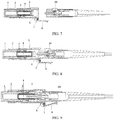
- FIG. 1b is a schematic structural diagram showing that the dustproof cover of the fiber adapter is not turned over according to this embodiment of the present invention.
- the dustproof cover 8 is mounted at one end of the second adapter body 5 by using the rotary spring 7.
- FIG. 1c is a schematic structural diagram when the dustproof cover 8 of the fiber adapter is turned over to a horizontal position according to this embodiment of the present invention.
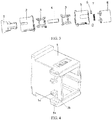
- FIG. 3 is a schematic exploded view of a fiber adapter according to an embodiment of the present invention.
- the fiber adapter includes a dustproof cap 1, a first adapter body 2, locks 3, a ceramic socket 4, a second adapter body 5, inclined blocks 6, a rotary spring 7, and a dustproof cover 8.
- the dustproof cap 1, the first adapter body 2, the locks 3, and the ceramic socket 4 are consistent with components of a common SC (Square Connector, square connector), and other description is not provided herein.
- SC Square Connector, square connector
- the dustproof cover 8 is provided with a hand-clasping position 8a used to turn over the dustproof cover 8.
- the hand-clasping position 8a may be a groove provided at a top end of the dustproof cover, may be a handle disposed on the dustproof cover, may be a circular hole provided on the dustproof cover, or may be a tether tied on the dustproof cover.
- the hand-clasping position 8a in this embodiment of the present invention may alternatively be another handle that is seen in daily life and that is used to facilitate opening of a component.
- an end that is of the dustproof cover 8 and that is connected to the second adapter body 5 is provided with a claw 8d.
- the claw 8d is fastened on the dustproof cover 8, and the claw 8d includes a protruding portion (not shown in the figure).
- the claw 8d is provided with a rotating shaft 8b, a pin shaft 8e, and a projection 8c, and the projection 8c is located outside the protruding portion of the claw 8d.
- the claw 8d may also be referred to as a connecting piece, used to connect to the second adapter body 5.
- the projection 8c may be a projection of any shape, and is preferably of a cylindrical shape.
- the rotating shaft 8b is of a cylindrical shape, and the rotating shaft 8b is used to be inserted into a first circular hole (as shown in FIG. 4 ) provided in a base 5a on a bottom portion of the second adapter body 5, so that the dustproof cover can be turned over relative to the second adapter body 5.
- the first circular hole may alternatively be referred to as a coupling portion, used to couple to the rotating shaft 8b.
- the pin shaft 8e is preferably of a cylindrical shape, and is mounted on a side that is of the claw 8d and that is opposite to the rotating shaft 8b. There are two pin shafts symmetrically disposed inside the two claws 8d of the dustproof cover.
- the two pin shafts 8e are used to mount the rotary spring 7. One end of the rotary spring 7 sleeves on a first pin shaft 8e and abuts against a first claw 8d, and another end of the rotary spring is used to sleeve on a second pin shaft 8e and abuts against a second claw 8d, so that the rotary spring 7 is mounted on the two pin shafts 8e, to apply a torsion force.
- the projection 8c is disposed outside the protruding portion of the claw 8d, and is preferably of a cylindrical shape, or may be of another column shape. When the dustproof cover is turned over, the projection 8c can be jammed in a second circular hole provided in the base 5a on the bottom portion of the second adapter body 5, so that the dustproof cover can remain horizontal. Details are shown in FIG. 1c .
- FIG. 4 is a schematic enlarged view of a bottom surface of the second adapter body 5.
- Two ends of the bottom surface of the second adapter body 5 are respectively provided with two bases 5a, and each base 5a is provided with two circular holes.
- the two circular holes are referred to as a first circular hole and a second circular hole.
- the bottom surface of the second adapter body 5 is provided, between the two bases 5a, with two opposite buckles 5c and holes 5b for the inclined block 6 to vertically slide.
- a shape of the hole 5b may be a circular shape, a square shape, or another shape, and is not limited herein.
- the buckle 5c has a height relative to the bottom surface of the second adapter body 5.
- a top end of the buckle 5c is formed into a hook shape bent toward a side, and is used to prevent the inclined block 6 from sliding out of the hole 5b.
- the height of the buckle 5c is less than a height of the inclined block 6.
- the first circular hole is used to adapt to the rotating shaft 8b disposed on the dustproof cover, so that the dustproof cover 8 can be turned over relative to the second adapter body 5.
- the second circular hole is used to adapt to the projection 8c disposed on the dustproof cover 8, and when the dustproof cover 8 is turned over, the projection 8c can be jammed in the second circular hole, so that the dustproof cover 8 is turned over to a horizontal plane and does not rebound.
- FIG. 6 is a schematic structural diagram of the inclined block 6.
- the inclined block 6 is embedded into the bottom surface of the second adapter body through the hole provided in the bottom surface of the second adapter body 5.
- the inclined block 6 includes a trapezoid and a cuboid.
- the trapezoid of the inclined block 6 is referred to as an upper component, and the cuboid of the inclined block 6 is referred to as a lower component.
- An end 6a of the upper component is a bevel, and the end 6a is located inside the second adapter body 5.
- the lower component of the inclined block 6 is a cuboid block.
- the cuboid block should be larger than the hole 5b, so that the cuboid block cannot slide into inside of the second adapter body 5 through the hole 5b.
- a length of the inclined block 6 (a length form the bevel 6a to a bottom end 6b) should be greater than the height of the buckle 5c, so that the bevel 6a of the inclined block 6 protrudes from an inner side of the bottom surface of the second adapter body 5.
- FIG. 1c it can be learned from FIG. 1c that the bevel 6a protrudes from the inner side of the bottom surface of the second adapter body 5.
- the dustproof cover 8 When the dustproof cover 8 is turned over to a horizontal direction and remains in the horizontal direction, in this case, if an optical fiber connector is inserted into the fiber adapter provided the optical fiber connector presses the bevel 6a of the inclined block 6, so that another end 6b of the inclined block presses the projection 8c of the dustproof cover 8 outward, the projection 8c bounces out of the second circular hole of the base 5a, and the dustproof cover 8 bounces, under an action of the rotary spring 7, to be of a shape shown in FIG. 9 .
- the dustproof cover 8 abuts against a side wall of the optical fiber connector. When the optical fiber connector is pulled out from the fiber adapter the dustproof cover recovers back to an initial state under the action of the rotary spring 7, as shown in FIG. 1a .
- the fiber adapter provided in the present invention can implement a one-hand operation. Details are as follows: The dustproof cover in the initial state shown in FIG. 1a is manually turned over to the horizontal position shown in FIG. 1c . Because under an action of a hand, the projection 8c on the dustproof cover slides into the second circular hole in the base 5a on the bottom portion of the second adapter body 5, a torsion force of the rotary spring 7 is counterbalanced and the dustproof cover remains at the position. In addition, the inclined block 6 is lifted by the claw 8d of the dustproof cover 8, and is higher than a bottom surface of an inner cavity of the adapter, so that the dustproof cover can remain at the horizontal position.
- the optical fiber connector can be inserted into the adapter with one hand, which is simple and convenient, and improves operation efficiency.
- the dustproof cover 8 rotates anticlockwise under the action of the rotary spring 7 and is automatically closed.
- the dustproof cover 8 automatically recovers back to the initial state shown in FIG. 1a .
- Limiting of the inclined block 6 between positions at upper and lower ends is implemented by using the buckle 5c of the second adapter body 5 and a boss 6b on the bottom surface, and the inclined block 6 does not fall out.
- the inclined block 6 is lifted upward by the claw 8d, the boss 6b on the bottom surface of the inclined block 6 comes into contact with the bottom surface of the second adapter body 5, to implement the limiting.
- the inclined block 6 is pressed downward by the optical fiber connector 20, the bottom surface of the inclined block 6 comes into contact with the buckle 5c, to implement the limiting.
- the dustproof cover of the fiber adapter provided in the present invention can be locked when being turned over to the horizontal position.
- the locked dustproof cover can be unlocked.
- the dustproof cover can be further automatically closed, so that an operation can be performed with one hand during actual insertion and pull-out operations.
- the fiber adapter is simple and easy to use.
Landscapes
- Physics & Mathematics (AREA)
- General Physics & Mathematics (AREA)
- Optics & Photonics (AREA)
- Mechanical Coupling Of Light Guides (AREA)
Claims (5)
- Faseradapter, umfassend eine staubdichte Kappe (1), ein erstes Adaptergehäuse (2) und ein zweites Adaptergehäuse (5), wobei der Faseradapter ferner eine staubdichte Abdeckung (8), eine Drehfeder (7) und Schrägblöcke (6) umfasst, wobei die staubdichte Abdeckung (8) durch Verwenden der Drehfeder (7) an einem Ende des zweiten Adaptergehäuses (5) befestigt ist; und
wobei der Schrägblock (6) durch ein Loch (5b), das in der Unterseite des zweiten Adaptergehäuses (5) bereitgestellt ist, in eine Unterseite des zweiten Adaptergehäuses (5) eingebettet ist und der Schrägblock (6) vertikal durch das Loch (5b) gleiten kann; wobei ein Ende der staubdichten Abdeckung (8), das mit dem zweiten Adaptergehäuse (5) verbunden ist, mit einer Klaue (8d) versehen ist; die Klaue (8d) an der staubdichten Abdeckung (8) befestigt ist; die Klaue (8d) mit einer Drehwelle (8b), einer Stiftwelle (8e) und einem Vorsprung (8c) versehen ist und sich der Vorsprung (8c) außerhalb eines vorstehenden Abschnitts der Klaue (8d) befindet;
wobei eine Basis (5a) an einem unteren Abschnitt des zweiten Adaptergehäuses (5) mit einem ersten Kreisloch und einem zweiten Kreisloch versehen ist; das erste Kreisloch zum Anpassen an die Drehwelle (8b), die an der staubdichten Abdeckung angeordnet ist, verwendet wird, sodass die staubdichte Abdeckung (8) bezogen auf das zweite Adaptergehäuse (5) umgeklappt werden kann; und das zweite Kreisloch zum Anpassen an den Vorsprung (8c), der an der staubdichten Abdeckung (8) angeordnet ist, verwendet wird, und wenn die staubdichte Abdeckung (8) umgeklappt wird, der Vorsprung (8c) in das zweite Kreisloch geklemmt werden kann, sodass die staubdichte Abdeckung (8) in eine horizontale Ebene umgeklappt wird und nicht zurückfedert; wobei der Faseradapter ferner derart angeordnet ist, dass, wenn ein faseroptischer Steckverbinder eingeführt wird, der faseroptische Steckverbinder derart gegen den Schrägblock (6) drückt, dass ein anderes Ende (6b) des Schrägblocks (6) den Vorsprung (8c) der staubdichten Abdeckung (8) nach außen drückt und der Vorsprung (8c) aus dem zweiten Kreisloch der Basis (5a) springt. - Faseradapter nach Anspruch 1, wobei der Schrägblock (6) eine obere Komponente und eine untere Komponente umfasst, die obere Komponente ein Trapezoid ist, die untere Komponente ein Quader ist, eine Oberfläche (6a) der oberen Komponente eine Schrägkante ist und der Quader größer als das Loch (5b) ist, sodass der Quader nicht durch das Loch (5b) in das zweite Adaptergehäuse (5) gleiten kann.
- Faseradapter nach einem der Ansprüche 1 oder Anspruch 2, wobei die Unterseite des zweiten Adaptergehäuses (5) mit Klammern (5c) zwischen zwei Basen (5a) versehen ist und ein oberes Ende der Klammer (5c) hakenförmig ist und zum Verhindern, dass der Schrägblock (6) aus dem Loch (5b) gleitet, verwendet wird.
- Faseradapter nach einem der Ansprüche 1 bis 3, wobei die Stiftwelle (8e) zum Befestigen der Drehfeder (7) zum Aufbringen einer Torsionskraft, die es ermöglicht, dass die staubdichte Abdeckung (8) automatisch geschlossen wird, verwendet wird.
- Faseradapter nach einem der Ansprüche 1 bis 4, wobei, wenn der faseroptische Steckverbinder herausgezogen wird, die staubdichte Abdeckung (8) unter einer Wirkung der Drehfeder (7) automatisch geschlossen wird.
Applications Claiming Priority (1)
| Application Number | Priority Date | Filing Date | Title |
|---|---|---|---|
| PCT/CN2015/097743 WO2017101081A1 (zh) | 2015-12-17 | 2015-12-17 | 一种光纤适配器 |
Publications (3)
| Publication Number | Publication Date |
|---|---|
| EP3376271A1 EP3376271A1 (de) | 2018-09-19 |
| EP3376271A4 EP3376271A4 (de) | 2018-11-14 |
| EP3376271B1 true EP3376271B1 (de) | 2021-09-01 |
Family
ID=59055482
Family Applications (1)
| Application Number | Title | Priority Date | Filing Date |
|---|---|---|---|
| EP15910552.7A Active EP3376271B1 (de) | 2015-12-17 | 2015-12-17 | Faseroptischer adapter |
Country Status (3)
| Country | Link |
|---|---|
| EP (1) | EP3376271B1 (de) |
| CN (1) | CN108292019B (de) |
| WO (1) | WO2017101081A1 (de) |
Families Citing this family (5)
| Publication number | Priority date | Publication date | Assignee | Title |
|---|---|---|---|---|
| CN109212677A (zh) * | 2017-07-06 | 2019-01-15 | 科大国盾量子技术股份有限公司 | 一种光纤法兰保护装置 |
| WO2021021575A1 (en) | 2019-07-26 | 2021-02-04 | Commscope Technologies Llc | Fiber optic adapters convertible between different polarity types |
| CN113176636B (zh) * | 2021-05-06 | 2023-08-11 | 四川天邑康和通信股份有限公司 | 一种通用型端面检测ec型光纤活动连接器 |
| CN114706171B (zh) * | 2022-03-31 | 2023-04-07 | 江西明鸿光电科技有限公司 | 一种防脱落多芯保偏光纤连接器 |
| CN120028920B (zh) * | 2025-04-23 | 2025-06-27 | 江苏通鼎宽带有限公司 | 快捷插拔的光纤活动连接器 |
Citations (2)
| Publication number | Priority date | Publication date | Assignee | Title |
|---|---|---|---|---|
| US20130108233A1 (en) * | 2011-10-27 | 2013-05-02 | Ezontek Technologies Co., Ltd. | Protection cap for optical fiber adapter |
| US20130272671A1 (en) * | 2012-04-13 | 2013-10-17 | Ashley W. Jones | Adapter for fiber optic connectors |
Family Cites Families (13)
| Publication number | Priority date | Publication date | Assignee | Title |
|---|---|---|---|---|
| EP1338909B1 (de) * | 2000-07-03 | 2007-03-28 | Yazaki Corporation | Optischer und hybrider Stecker |
| US6688780B2 (en) * | 2002-02-07 | 2004-02-10 | Amphenol Corporation | Cantilevered shutter for optical adapter |
| US6702475B1 (en) * | 2002-05-07 | 2004-03-09 | Cisco Technology, Inc. | Release system for optical connectors |
| CN101726804B (zh) * | 2009-11-03 | 2011-08-03 | 无锡光太光通讯器件有限公司 | 自动开合式防尘帽光纤连接器 |
| CN102305962B (zh) * | 2011-09-27 | 2013-07-10 | 深圳日海通讯技术股份有限公司 | 一种光纤连接器 |
| WO2012163006A1 (zh) * | 2011-10-14 | 2012-12-06 | 华为技术有限公司 | 光纤连接器和光通信系统 |
| CN202305907U (zh) * | 2011-11-09 | 2012-07-04 | 奉化市宇达高科光电器件有限公司 | 一种光纤适配器 |
| CN104238033B (zh) * | 2012-06-18 | 2016-05-25 | 华为技术有限公司 | 光纤适配器和光纤连接器 |
| US9075205B2 (en) * | 2012-07-11 | 2015-07-07 | Tyco Electronics Corporation | Connectors and adapters with auto-latching features |
| JP6400892B2 (ja) * | 2013-09-17 | 2018-10-03 | 三和電気工業株式会社 | Lc形光コネクタの防塵シャッタ内蔵アダプタ |
| JP6234243B2 (ja) * | 2014-01-24 | 2017-11-22 | オリンパス株式会社 | 光ファイバの接続アダプタおよび内視鏡装置 |
| CN204515191U (zh) * | 2015-01-13 | 2015-07-29 | 深圳市龙晟光电有限公司 | 光纤连接器 |
| CN204832587U (zh) * | 2015-08-13 | 2015-12-02 | 乐清市得信电子有限公司 | 两瓣式光纤适配器 |
-
2015
- 2015-12-17 WO PCT/CN2015/097743 patent/WO2017101081A1/zh not_active Ceased
- 2015-12-17 CN CN201580085044.1A patent/CN108292019B/zh active Active
- 2015-12-17 EP EP15910552.7A patent/EP3376271B1/de active Active
Patent Citations (2)
| Publication number | Priority date | Publication date | Assignee | Title |
|---|---|---|---|---|
| US20130108233A1 (en) * | 2011-10-27 | 2013-05-02 | Ezontek Technologies Co., Ltd. | Protection cap for optical fiber adapter |
| US20130272671A1 (en) * | 2012-04-13 | 2013-10-17 | Ashley W. Jones | Adapter for fiber optic connectors |
Also Published As
| Publication number | Publication date |
|---|---|
| CN108292019B (zh) | 2020-07-24 |
| WO2017101081A1 (zh) | 2017-06-22 |
| EP3376271A4 (de) | 2018-11-14 |
| CN108292019A (zh) | 2018-07-17 |
| EP3376271A1 (de) | 2018-09-19 |
Similar Documents
| Publication | Publication Date | Title |
|---|---|---|
| EP3376271B1 (de) | Faseroptischer adapter | |
| US9423575B2 (en) | Small form-factor pluggable connector | |
| US20130108233A1 (en) | Protection cap for optical fiber adapter | |
| CN201820018U (zh) | 一种sfp光收发一体模块 | |
| US9279940B2 (en) | Optical fiber adapter with shutter member | |
| CN101494337A (zh) | 具有滑动部件的连接器组件 | |
| WO2020253154A1 (zh) | 一种光模块解锁装置 | |
| JP2012053375A (ja) | 多連結型光コネクタ | |
| US20130183004A1 (en) | Loopback Housing for a Fiber Optic Connector | |
| US20150117820A1 (en) | Optical fiber adapter with shutter member | |
| JP4377820B2 (ja) | 光コネクタのロック解除機構 | |
| CN102141659B (zh) | 光模块 | |
| JP2011027876A (ja) | 多連結型光コネクタ | |
| WO2020237821A1 (zh) | 连接器组件 | |
| TWM618563U (zh) | 拉帶解鎖連接器 | |
| CN209496177U (zh) | 一种可插拔光模块的外壳结构 | |
| CN110202262B (zh) | 激光焊接头和激光焊接机 | |
| CN204269868U (zh) | 光纤适配器 | |
| CN107092059A (zh) | 光模块解锁装置 | |
| US12554088B2 (en) | Fiber-optic terminal box | |
| CN217820979U (zh) | 一种方便锁止和解锁的sfp光模块 | |
| CN207081863U (zh) | 光模块解锁装置 | |
| CN215005984U (zh) | 一种小型光纤连接器 | |
| TWI729799B (zh) | 插接結構 | |
| CN210347998U (zh) | 连接器 |
Legal Events
| Date | Code | Title | Description |
|---|---|---|---|
| STAA | Information on the status of an ep patent application or granted ep patent |
Free format text: STATUS: THE INTERNATIONAL PUBLICATION HAS BEEN MADE |
|
| PUAI | Public reference made under article 153(3) epc to a published international application that has entered the european phase |
Free format text: ORIGINAL CODE: 0009012 |
|
| STAA | Information on the status of an ep patent application or granted ep patent |
Free format text: STATUS: REQUEST FOR EXAMINATION WAS MADE |
|
| 17P | Request for examination filed |
Effective date: 20180613 |
|
| AK | Designated contracting states |
Kind code of ref document: A1 Designated state(s): AL AT BE BG CH CY CZ DE DK EE ES FI FR GB GR HR HU IE IS IT LI LT LU LV MC MK MT NL NO PL PT RO RS SE SI SK SM TR |
|
| AX | Request for extension of the european patent |
Extension state: BA ME |
|
| A4 | Supplementary search report drawn up and despatched |
Effective date: 20181017 |
|
| RIC1 | Information provided on ipc code assigned before grant |
Ipc: G02B 6/38 20060101AFI20181011BHEP Ipc: G02B 6/44 20060101ALI20181011BHEP |
|
| DAV | Request for validation of the european patent (deleted) | ||
| DAX | Request for extension of the european patent (deleted) | ||
| GRAP | Despatch of communication of intention to grant a patent |
Free format text: ORIGINAL CODE: EPIDOSNIGR1 |
|
| STAA | Information on the status of an ep patent application or granted ep patent |
Free format text: STATUS: GRANT OF PATENT IS INTENDED |
|
| INTG | Intention to grant announced |
Effective date: 20210408 |
|
| GRAS | Grant fee paid |
Free format text: ORIGINAL CODE: EPIDOSNIGR3 |
|
| GRAA | (expected) grant |
Free format text: ORIGINAL CODE: 0009210 |
|
| STAA | Information on the status of an ep patent application or granted ep patent |
Free format text: STATUS: THE PATENT HAS BEEN GRANTED |
|
| AK | Designated contracting states |
Kind code of ref document: B1 Designated state(s): AL AT BE BG CH CY CZ DE DK EE ES FI FR GB GR HR HU IE IS IT LI LT LU LV MC MK MT NL NO PL PT RO RS SE SI SK SM TR |
|
| REG | Reference to a national code |
Ref country code: GB Ref legal event code: FG4D |
|
| REG | Reference to a national code |
Ref country code: CH Ref legal event code: EP Ref country code: AT Ref legal event code: REF Ref document number: 1426818 Country of ref document: AT Kind code of ref document: T Effective date: 20210915 |
|
| REG | Reference to a national code |
Ref country code: DE Ref legal event code: R096 Ref document number: 602015072998 Country of ref document: DE |
|
| REG | Reference to a national code |
Ref country code: IE Ref legal event code: FG4D |
|
| REG | Reference to a national code |
Ref country code: FI Ref legal event code: FGE |
|
| REG | Reference to a national code |
Ref country code: LT Ref legal event code: MG9D |
|
| REG | Reference to a national code |
Ref country code: NL Ref legal event code: MP Effective date: 20210901 |
|
| PG25 | Lapsed in a contracting state [announced via postgrant information from national office to epo] |
Ref country code: LT Free format text: LAPSE BECAUSE OF FAILURE TO SUBMIT A TRANSLATION OF THE DESCRIPTION OR TO PAY THE FEE WITHIN THE PRESCRIBED TIME-LIMIT Effective date: 20210901 Ref country code: BG Free format text: LAPSE BECAUSE OF FAILURE TO SUBMIT A TRANSLATION OF THE DESCRIPTION OR TO PAY THE FEE WITHIN THE PRESCRIBED TIME-LIMIT Effective date: 20211201 Ref country code: NO Free format text: LAPSE BECAUSE OF FAILURE TO SUBMIT A TRANSLATION OF THE DESCRIPTION OR TO PAY THE FEE WITHIN THE PRESCRIBED TIME-LIMIT Effective date: 20211201 Ref country code: ES Free format text: LAPSE BECAUSE OF FAILURE TO SUBMIT A TRANSLATION OF THE DESCRIPTION OR TO PAY THE FEE WITHIN THE PRESCRIBED TIME-LIMIT Effective date: 20210901 Ref country code: HR Free format text: LAPSE BECAUSE OF FAILURE TO SUBMIT A TRANSLATION OF THE DESCRIPTION OR TO PAY THE FEE WITHIN THE PRESCRIBED TIME-LIMIT Effective date: 20210901 Ref country code: RS Free format text: LAPSE BECAUSE OF FAILURE TO SUBMIT A TRANSLATION OF THE DESCRIPTION OR TO PAY THE FEE WITHIN THE PRESCRIBED TIME-LIMIT Effective date: 20210901 Ref country code: SE Free format text: LAPSE BECAUSE OF FAILURE TO SUBMIT A TRANSLATION OF THE DESCRIPTION OR TO PAY THE FEE WITHIN THE PRESCRIBED TIME-LIMIT Effective date: 20210901 |
|
| REG | Reference to a national code |
Ref country code: AT Ref legal event code: MK05 Ref document number: 1426818 Country of ref document: AT Kind code of ref document: T Effective date: 20210901 |
|
| PG25 | Lapsed in a contracting state [announced via postgrant information from national office to epo] |
Ref country code: PL Free format text: LAPSE BECAUSE OF FAILURE TO SUBMIT A TRANSLATION OF THE DESCRIPTION OR TO PAY THE FEE WITHIN THE PRESCRIBED TIME-LIMIT Effective date: 20210901 Ref country code: LV Free format text: LAPSE BECAUSE OF FAILURE TO SUBMIT A TRANSLATION OF THE DESCRIPTION OR TO PAY THE FEE WITHIN THE PRESCRIBED TIME-LIMIT Effective date: 20210901 Ref country code: GR Free format text: LAPSE BECAUSE OF FAILURE TO SUBMIT A TRANSLATION OF THE DESCRIPTION OR TO PAY THE FEE WITHIN THE PRESCRIBED TIME-LIMIT Effective date: 20211202 |
|
| PG25 | Lapsed in a contracting state [announced via postgrant information from national office to epo] |
Ref country code: AT Free format text: LAPSE BECAUSE OF FAILURE TO SUBMIT A TRANSLATION OF THE DESCRIPTION OR TO PAY THE FEE WITHIN THE PRESCRIBED TIME-LIMIT Effective date: 20210901 |
|
| PG25 | Lapsed in a contracting state [announced via postgrant information from national office to epo] |
Ref country code: IS Free format text: LAPSE BECAUSE OF FAILURE TO SUBMIT A TRANSLATION OF THE DESCRIPTION OR TO PAY THE FEE WITHIN THE PRESCRIBED TIME-LIMIT Effective date: 20220101 Ref country code: SM Free format text: LAPSE BECAUSE OF FAILURE TO SUBMIT A TRANSLATION OF THE DESCRIPTION OR TO PAY THE FEE WITHIN THE PRESCRIBED TIME-LIMIT Effective date: 20210901 Ref country code: SK Free format text: LAPSE BECAUSE OF FAILURE TO SUBMIT A TRANSLATION OF THE DESCRIPTION OR TO PAY THE FEE WITHIN THE PRESCRIBED TIME-LIMIT Effective date: 20210901 Ref country code: RO Free format text: LAPSE BECAUSE OF FAILURE TO SUBMIT A TRANSLATION OF THE DESCRIPTION OR TO PAY THE FEE WITHIN THE PRESCRIBED TIME-LIMIT Effective date: 20210901 Ref country code: PT Free format text: LAPSE BECAUSE OF FAILURE TO SUBMIT A TRANSLATION OF THE DESCRIPTION OR TO PAY THE FEE WITHIN THE PRESCRIBED TIME-LIMIT Effective date: 20220103 Ref country code: NL Free format text: LAPSE BECAUSE OF FAILURE TO SUBMIT A TRANSLATION OF THE DESCRIPTION OR TO PAY THE FEE WITHIN THE PRESCRIBED TIME-LIMIT Effective date: 20210901 Ref country code: EE Free format text: LAPSE BECAUSE OF FAILURE TO SUBMIT A TRANSLATION OF THE DESCRIPTION OR TO PAY THE FEE WITHIN THE PRESCRIBED TIME-LIMIT Effective date: 20210901 Ref country code: CZ Free format text: LAPSE BECAUSE OF FAILURE TO SUBMIT A TRANSLATION OF THE DESCRIPTION OR TO PAY THE FEE WITHIN THE PRESCRIBED TIME-LIMIT Effective date: 20210901 Ref country code: AL Free format text: LAPSE BECAUSE OF FAILURE TO SUBMIT A TRANSLATION OF THE DESCRIPTION OR TO PAY THE FEE WITHIN THE PRESCRIBED TIME-LIMIT Effective date: 20210901 |
|
| REG | Reference to a national code |
Ref country code: DE Ref legal event code: R097 Ref document number: 602015072998 Country of ref document: DE |
|
| PLBE | No opposition filed within time limit |
Free format text: ORIGINAL CODE: 0009261 |
|
| STAA | Information on the status of an ep patent application or granted ep patent |
Free format text: STATUS: NO OPPOSITION FILED WITHIN TIME LIMIT |
|
| PG25 | Lapsed in a contracting state [announced via postgrant information from national office to epo] |
Ref country code: MC Free format text: LAPSE BECAUSE OF FAILURE TO SUBMIT A TRANSLATION OF THE DESCRIPTION OR TO PAY THE FEE WITHIN THE PRESCRIBED TIME-LIMIT Effective date: 20210901 Ref country code: IT Free format text: LAPSE BECAUSE OF FAILURE TO SUBMIT A TRANSLATION OF THE DESCRIPTION OR TO PAY THE FEE WITHIN THE PRESCRIBED TIME-LIMIT Effective date: 20210901 Ref country code: DK Free format text: LAPSE BECAUSE OF FAILURE TO SUBMIT A TRANSLATION OF THE DESCRIPTION OR TO PAY THE FEE WITHIN THE PRESCRIBED TIME-LIMIT Effective date: 20210901 |
|
| REG | Reference to a national code |
Ref country code: CH Ref legal event code: PL |
|
| 26N | No opposition filed |
Effective date: 20220602 |
|
| GBPC | Gb: european patent ceased through non-payment of renewal fee |
Effective date: 20211217 |
|
| PG25 | Lapsed in a contracting state [announced via postgrant information from national office to epo] |
Ref country code: SI Free format text: LAPSE BECAUSE OF FAILURE TO SUBMIT A TRANSLATION OF THE DESCRIPTION OR TO PAY THE FEE WITHIN THE PRESCRIBED TIME-LIMIT Effective date: 20210901 |
|
| REG | Reference to a national code |
Ref country code: BE Ref legal event code: MM Effective date: 20211231 |
|
| PG25 | Lapsed in a contracting state [announced via postgrant information from national office to epo] |
Ref country code: LU Free format text: LAPSE BECAUSE OF NON-PAYMENT OF DUE FEES Effective date: 20211217 Ref country code: IE Free format text: LAPSE BECAUSE OF NON-PAYMENT OF DUE FEES Effective date: 20211217 Ref country code: GB Free format text: LAPSE BECAUSE OF NON-PAYMENT OF DUE FEES Effective date: 20211217 |
|
| PG25 | Lapsed in a contracting state [announced via postgrant information from national office to epo] |
Ref country code: FR Free format text: LAPSE BECAUSE OF NON-PAYMENT OF DUE FEES Effective date: 20211231 Ref country code: BE Free format text: LAPSE BECAUSE OF NON-PAYMENT OF DUE FEES Effective date: 20211231 |
|
| PG25 | Lapsed in a contracting state [announced via postgrant information from national office to epo] |
Ref country code: LI Free format text: LAPSE BECAUSE OF NON-PAYMENT OF DUE FEES Effective date: 20211231 Ref country code: CH Free format text: LAPSE BECAUSE OF NON-PAYMENT OF DUE FEES Effective date: 20211231 |
|
| PG25 | Lapsed in a contracting state [announced via postgrant information from national office to epo] |
Ref country code: HU Free format text: LAPSE BECAUSE OF FAILURE TO SUBMIT A TRANSLATION OF THE DESCRIPTION OR TO PAY THE FEE WITHIN THE PRESCRIBED TIME-LIMIT; INVALID AB INITIO Effective date: 20151217 |
|
| PG25 | Lapsed in a contracting state [announced via postgrant information from national office to epo] |
Ref country code: CY Free format text: LAPSE BECAUSE OF FAILURE TO SUBMIT A TRANSLATION OF THE DESCRIPTION OR TO PAY THE FEE WITHIN THE PRESCRIBED TIME-LIMIT Effective date: 20210901 |
|
| PG25 | Lapsed in a contracting state [announced via postgrant information from national office to epo] |
Ref country code: MK Free format text: LAPSE BECAUSE OF FAILURE TO SUBMIT A TRANSLATION OF THE DESCRIPTION OR TO PAY THE FEE WITHIN THE PRESCRIBED TIME-LIMIT Effective date: 20210901 |
|
| PG25 | Lapsed in a contracting state [announced via postgrant information from national office to epo] |
Ref country code: TR Free format text: LAPSE BECAUSE OF FAILURE TO SUBMIT A TRANSLATION OF THE DESCRIPTION OR TO PAY THE FEE WITHIN THE PRESCRIBED TIME-LIMIT Effective date: 20210901 |
|
| PG25 | Lapsed in a contracting state [announced via postgrant information from national office to epo] |
Ref country code: MT Free format text: LAPSE BECAUSE OF FAILURE TO SUBMIT A TRANSLATION OF THE DESCRIPTION OR TO PAY THE FEE WITHIN THE PRESCRIBED TIME-LIMIT Effective date: 20210901 |
|
| PGFP | Annual fee paid to national office [announced via postgrant information from national office to epo] |
Ref country code: DE Payment date: 20251104 Year of fee payment: 11 |
|
| PGFP | Annual fee paid to national office [announced via postgrant information from national office to epo] |
Ref country code: FI Payment date: 20251211 Year of fee payment: 11 |