EP3376126A1 - Air conditioning system - Google Patents
Air conditioning system Download PDFInfo
- Publication number
- EP3376126A1 EP3376126A1 EP16864307.0A EP16864307A EP3376126A1 EP 3376126 A1 EP3376126 A1 EP 3376126A1 EP 16864307 A EP16864307 A EP 16864307A EP 3376126 A1 EP3376126 A1 EP 3376126A1
- Authority
- EP
- European Patent Office
- Prior art keywords
- temperature
- unit
- indoor unit
- indoor
- air conditioning
- Prior art date
- Legal status (The legal status is an assumption and is not a legal conclusion. Google has not performed a legal analysis and makes no representation as to the accuracy of the status listed.)
- Granted
Links
Images



Classifications
-
- F—MECHANICAL ENGINEERING; LIGHTING; HEATING; WEAPONS; BLASTING
- F24—HEATING; RANGES; VENTILATING
- F24F—AIR-CONDITIONING; AIR-HUMIDIFICATION; VENTILATION; USE OF AIR CURRENTS FOR SCREENING
- F24F11/00—Control or safety arrangements
- F24F11/30—Control or safety arrangements for purposes related to the operation of the system, e.g. for safety or monitoring
- F24F11/49—Control or safety arrangements for purposes related to the operation of the system, e.g. for safety or monitoring ensuring correct operation, e.g. by trial operation or configuration checks
-
- F—MECHANICAL ENGINEERING; LIGHTING; HEATING; WEAPONS; BLASTING
- F24—HEATING; RANGES; VENTILATING
- F24F—AIR-CONDITIONING; AIR-HUMIDIFICATION; VENTILATION; USE OF AIR CURRENTS FOR SCREENING
- F24F1/00—Room units for air-conditioning, e.g. separate or self-contained units or units receiving primary air from a central station
- F24F1/0007—Indoor units, e.g. fan coil units
- F24F1/0068—Indoor units, e.g. fan coil units characterised by the arrangement of refrigerant piping outside the heat exchanger within the unit casing
-
- F—MECHANICAL ENGINEERING; LIGHTING; HEATING; WEAPONS; BLASTING
- F24—HEATING; RANGES; VENTILATING
- F24F—AIR-CONDITIONING; AIR-HUMIDIFICATION; VENTILATION; USE OF AIR CURRENTS FOR SCREENING
- F24F2221/00—Details or features not otherwise provided for
- F24F2221/54—Heating and cooling, simultaneously or alternatively
Definitions
- Embodiments of the present invention relate to an air conditioning system.
- an air conditioning system in which a plurality of indoor units are connected to one outdoor unit through a refrigerant pipe and a communication line is known.
- this type of air conditioning system in some cases, it is determined whether or not the connection between the pipe and the communication line is correct, on the basis of a change in the refrigerant temperature before and after supplying the refrigerant to the pipe which is acquired from a sensor that detects a refrigerant temperature via a heat exchanger.
- Patent Document 1 Japanese Unexamined Patent Application, First Publication No. H5-33982
- An object to be solved by the present invention is to provide an air conditioning system capable of more accurately determining whether a pipe or a communication line is correctly connected.
- An air conditioning system includes an outdoor unit, a first indoor unit, a second indoor unit, a first temperature determination unit, a second temperature determination unit, a third temperature determination unit, a fourth temperature determination unit, and a control unit.
- the outdoor unit has at least a compressor and is connectable to a refrigerant pipe system.
- the first indoor unit has a first heat exchanger and is connectable to the refrigerant pipe system.
- the second indoor unit has a second heat exchanger and is connectable to the refrigerant pipe system.
- the first temperature determination unit is configured to determine the temperature of the first heat exchanger.
- the second temperature determination unit is configured to determine the temperature of the second heat exchanger.
- the third temperature determination unit is provided for the first indoor unit and configured to determine the temperature of an air conditioning target space associated with the first indoor unit.
- the fourth temperature determination unit is provided for the second indoor unit and configured to determine the temperature of an air conditioning target space associated with the second indoor unit.
- the control unit configured to determine whether at least one of a first refrigerant pipe connected to the first indoor unit of the refrigerant pipe system connected to the first indoor unit and a first communication line connected to the first indoor unit is correctly connected, when a first temperature difference between the temperature determined by the first temperature determination unit and the temperature determined by the third temperature determination unit is equal to or higher than a first threshold value, and a second temperature difference between the temperature determined by the second temperature determination unit and the temperature determined by the fourth temperature determination unit is less than a second threshold value.
- Fig. 1 is a diagram showing a configuration of an air conditioning system 1.
- the air conditioning system 1 may include an outdoor unit 10, and indoor units 30-1, 30-2, ... 30-n.
- indoor units 30 are installed, for example, in different rooms.
- the outdoor unit 10 and each indoor unit 30-1 are connected to connection pipes 2-1-1, 2-1-2, ... 2-n-2.
- the outdoor unit 10 includes a compressor 12, an accumulator 13, a four-way valve 14, an outdoor side heat exchanger 16, and expansion valves 18-1 to 18-n.
- the compressor 12 compresses the refrigerant and discharges the refrigerant to the refrigerant pipe 20 via the four-way valve 14.
- the compressor 12 circulates the refrigerant in the direction of an arrow in the drawing.
- the refrigerant is, for example, R410A, or R32. Further, the refrigerant may be a refrigerant containing 50% or more of R32.
- white arrows indicate the flow of the refrigerant at the time of cooling, and black arrows indicate the flow of the refrigerant at the time of heating.
- the accumulator 13 is provided to be adjacent to the compressor 12. The accumulator 13 separates the refrigerant returning to the compressor 12 into a gas-phase refrigerant and a liquid-phase refrigerant.
- the four-way valve 14 switches the direction in which the refrigerant discharged from the compressor 12 is circulated.
- the four-way valve 14 switches between a state in which the compressor 12 and the outdoor side heat exchanger 16 are electrically connected to each other, and a state in which the compressor 12 and the indoor side heat exchanger 32 are electrically connected to each other.
- the four-way valve 14 may circulate the refrigerant discharged from the compressor 12 to the outdoor side heat exchanger 16. Further, the four-way valve 14 circulates the refrigerant discharged from the compressor 12 to the connection pipes 2-1-1 and 2-n-1.
- the four-way valve 14, the outdoor side heat exchanger 16, and the expansion valves 18-1 to 18-n are connected to each other via the refrigerant pipes 20 and 21.
- expansion valves 18-1 to 18-n are simply referred to as expansion valves 18.
- the outdoor side heat exchanger 16 liquefies the refrigerant discharged from the compressor 12 and releases the heat contained in the refrigerant.
- the expansion valve 18 is connected to the indoor unit 30 via the connection pipe 2.
- the expansion valve 18 sets the temperature of the liquid refrigerant to low and sets the pressure of the liquid refrigerant to low, by controlling the pressure reduction and the flow rate of the refrigerant which has become the liquid discharged from the outdoor side heat exchanger 16.
- the indoor unit 30 includes an indoor side heat exchanger 32, a fan 34, an indoor side heat exchanger temperature sensor 36, and an indoor side temperature sensor 38.
- the indoor side heat exchanger 32 performs heat-exchange between the refrigerant discharged from the expansion valve 18 and air to evaporate the refrigerant.
- the fan 34 blows the air having undergone heat exchange via the indoor side heat exchanger 32 to an air conditioning target space
- the indoor side heat exchanger temperature sensor 36 determines the temperature of the indoor side heat exchanger 32.
- the indoor side temperature sensor 38 determines the temperature of the room in which the indoor unit 30 is installed.
- Fig. 2 is a diagram showing a configuration of a control unit of the air conditioning system 1.
- the air conditioning system 1 further includes an outdoor side operation unit 26, an outdoor side control unit 28, an indoor side operation unit 40, and an indoor side control unit 42.
- the outdoor side control unit 28 and the indoor side control unit 42 are connected to each other through a communication line and an electrical line.
- the outdoor side control unit 28 or the indoor side control unit 42 is, for example, a processor such as a central processing unit (CPU).
- the outdoor side control unit 28 or the indoor side control unit 42 may be hardware such as a large scale integration (LSI) or an application specific integrated circuit (ASIC).
- LSI large scale integration
- ASIC application specific integrated circuit
- the outdoor side operation unit 26 includes a mode switching button, a display unit, and the like.
- the outdoor side operation unit 26 supplies a signal corresponding to the operation of the user to the outdoor side control unit 28.
- the outdoor side operation unit 26 supplies a signal indicating that the instruction for the check operation has been given to the outdoor side control unit 28.
- the check operation is an operation of determining whether or not the pipe and the communication line between the outdoor unit 10 and the indoor unit 30 are connected normally (correctly)(details will be described later). Further, the display unit of the outdoor side operation unit 26 displays the results of the check operation or information indicating the abnormality of an air conditioning system 1.
- Indoor side operation units 40 are provided to correspond to each of the plurality of indoor units 30.
- the indoor side operation unit 40 includes a setting temperature changing button of an air conditioning target space of the indoor unit 30, an operation mode switching button, an indoor side display unit, and the like.
- the indoor side operation unit 40 supplies a signal corresponding to the user's operation to the indoor side control unit 42.
- the display unit of the indoor side operation unit 40 displays the operation state of the indoor unit 30, the state of the air conditioning target space, the set operation mode, and the like.
- the outdoor side control unit 28 controls the driving of the compressor 12.
- the outdoor side control unit 28 controls an opening degree of the valve of the expansion valve 18.
- the outdoor side control unit 28 generates an instruction signal, on the basis of the signal supplied from the indoor side operation unit 40 or information acquired from the indoor side control unit 42.
- the outdoor side control unit 28 supplies instruction signals to the compressor 12, the expansion valve 18, the outdoor side operation unit 26, and the indoor side control unit 42. Details of processes of the outdoor side control unit 28 will be described later.
- Indoor side control units 42 are provided to correspond to each of the plurality of indoor units 30.
- the indoor side control unit 42 controls each unit included in the indoor unit 30 on the basis of an instruction signal supplied from the outdoor side control unit 28.
- the indoor side control unit 42 supplies information or signals acquired from the indoor side heat exchanger temperature sensor 36, the indoor side temperature sensor 38, and the indoor side operation unit 40 to the outdoor side control unit 28.
- Fig. 3 is a flowchart showing the flow of a check operation (determination of whether or not the connection of the pipe or the communication line is normal) executed by the outdoor side control unit 28.
- the outdoor side control unit 28 selects an indoor unit 30 in which the determination of the connection state has not been completed, among the plurality of indoor units 30 (step S100).
- the outdoor side control unit 28 controls the fan 34 of the indoor unit 30 selected in step S100 in an ON state (step S102), and controls the expansion valves 18 of all the indoor units 30 in an open state (step S104).
- the outdoor side control unit 28 controls the air conditioning system 1 in a standby state for a predetermined time (step S106).
- the outdoor side control unit 28 executes a determining process of the connection state (step S108). Details of the determining process will be described later.
- the outdoor side control unit 28 determines whether or not the connection state of all the indoor units 30 has been determined (step S110). When the connection state of all the indoor units 30 has not been determined, the process returns to step S100. When the connection state of all the indoor units 30 has been determined, the process of the flowchart ends.
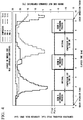
- Fig. 4 is a diagram showing an overview of the check operation performed by the outdoor side control unit 28.
- an indoor unit 30-1 having a room A as an air conditioning target space
- an indoor unit 30-2 having a room B as an air conditioning target space
- an indoor unit 30-3 having a room C as an air conditioning target space
- the determining process is executed one by one in order from the room A to the room C.
- the temperature change (TC-A to TC-C in the drawings) of the indoor side heat exchanger 32 in the chambers A and C from the start to the end of the check operation is shown.
- the open and closed states (PMV A to PMV C in the drawings) of the expansion valve 18 which circulates the refrigerant in the chambers A and C for each time, and the operation state of the compressor 12 for each time are shown.
- the outdoor side control unit 28 controls the compressor 12 in an ON state, and controls the expansion valve 18, which circulates the refrigerant in the indoor unit 30-1, in a predetermined open state.
- the outdoor side control unit 28 executes the determining process of the room A, and when the determining process of the room A ends, the outdoor side control unit 28 sets the compressor 12 to an OFF state and controls at least the fan 34 of the indoor unit 30-2 to the ON state.
- the fans 34 of all the indoor units 30-1 and 30-3 may be controlled to the ON state.
- the outdoor side control unit 28 controls the expansion valves 18 of the indoor units 30-1 and 30-3 to the open state. These states are maintained for a predetermined time.
- the interval time indicates the time for maintaining the compressor 12 is in the OFF state, maintaining at least the fan 34 of the indoor unit 30 as being subjected to the determining process of the connected state next is in the ON state, and maintaining all the expansion valves 18 is in the open state for the predetermined time
- the interval time is, for example, the time which is set for returning from the lowered temperature, on the assumption that the temperature of the indoor side heat exchanger 32 of the indoor unit 30-2, which becomes the target of the determining process of the connection state next, is lowered during the determining process of the indoor unit 30-1 which is the target of the immediately preceding determining process.
- the interval time may be a preset time. Further, the interval time may be a time determined by the outdoor side control unit 28 on the basis of the detection results of the indoor side heat exchanger temperature sensor 36 or the indoor side temperature sensor 38.
- the temperature of the indoor side heat exchanger 32 of the indoor unit 30 or the air conditioning target space is easily returned to that of a state before the determining process of the connection state was started. Further, by controlling the expansion valves 18 of the indoor units 30-1 to 30-3 to the open state, it is possible to suppress the temperature change or the like occurring in the indoor unit 30 connected to the part other than the pipe in which the refrigerant is circulated by the residual refrigerant in the pipe or the pressure change in the pipe.
- the determining process of the connection state of the room B is executed, and after the interval time has elapsed, the determining process of the connection state of the room C is executed. Thus, it is determined whether or not the pipe of the indoor unit 30 connected to the outdoor unit 10 and the communication line are connected normally.
- an indoor side expansion valve may be further provided between the connection pipe 2 of the indoor unit 30 and the indoor side heat exchanger 32, in addition to the expansion valve 18.
- an indoor side expansion valve different from the indoor side expansion valve included in the indoor unit 30 subject to the determining process may be controlled to the closed state.
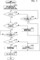
- Fig. 5 is a flowchart showing the flow of a determining process executed by the outdoor side control unit 28.
- the outdoor side control unit 28 controls the compressor 12 for the ON state and controls the expansion valve 18-1 of the indoor unit 30-1, which is a determination target of the connection state, to the predetermined open state (step S150).
- the indoor unit 30-1, which is a determination target for the connection state corresponds to the "first indoor unit” in the claims
- the indoor units 30-2 and 30-3 which are not determination targets of the connection state correspond to "an indoor unit other than the first indoor unit” in the claims.
- the indoor side heat exchanger 32-1 corresponds to the "first heat exchanger” in the claims
- the indoor side heat exchanger temperature sensor 36-1 corresponds to the "first temperature determination unit”
- the indoor side temperature sensor 38-1 corresponds to the "third temperature determination unit” in the claims.
- the indoor side heat exchangers 32-2 and 32-3 correspond to the "second heat exchanger” in the claims
- the indoor side heat exchanger temperature sensors 36-2 and 36-3 correspond to the “second temperature determination unit”
- the indoor side temperature sensors 38-2 and 38-3 correspond to the "fourth temperature determination unit” in the claims.
- the rotational speed of the compressor 12 is, for example, 25% or less of the maximum rotational speed of the compressor 12.
- the opening degree of the expansion valve 18-1 is, for example, 25% or less of the maximum flow opening degree of the expansion valve 18.
- the outdoor side control unit 28 determines whether or not a temperature difference ⁇ T is equal to or higher than a temperature T1 (step S152).
- the temperature difference ⁇ T is a difference between the temperature TA detected by the indoor side temperature sensor 38-1 of the indoor unit 30-1 on which determination is to be performed and the temperature TC detected by the indoor side heat exchanger temperature sensor 36-1 of the indoor unit 30-1 on which determination is to be performed.
- the outdoor side control unit 28 determines whether or not a predetermined time has elapsed (step S154). When the predetermined time has not elapsed, the process of step S152 is repeated. When the predetermined time has elapsed, the outdoor side control unit 28 determines that there is a possibility that an abnormality may exist in the connection state of the pipe and the communication line of the indoor unit 30-1 on which determination is to be performed (step S166). This is because the temperature determined by the indoor side heat exchanger temperature sensor 36-1 has not decreased by more than a predetermined temperature even though the refrigerant is circulated in the indoor unit 30-1 on which determination is to be performed.
- the outdoor side control unit 28 and the communication line with the indoor side control unit 42 are misconnected, and there is a possibility that a difference may occur between the indoor side control unit 42 to be controlled and the indoor side control unit 42 that is actually controlled.
- the pipe between the indoor unit 30-1 and the outdoor unit 10 is erroneously connected, and there is a possibility that a difference may occur between the indoor unit 30-1 of the target through which the refrigerant is circulated and the indoor unit 30 in which the refrigerant is actually circulated.
- the outdoor side control unit 28 determines whether or not the temperature difference ⁇ Tn is equal to or higher than the temperature T2 for all the other indoor units 30 (step S156).
- the temperature difference ⁇ Tn is a difference between the temperature TAn detected by the indoor side temperature sensor 38 of the indoor unit 30 which is not the determination target for the connection state and the temperature TCn detected by the indoor side heat exchanger temperature sensor 36 of the indoor unit 30 which is not the determination target for the connection state.
- the outdoor side control unit 28 calculates the temperature difference ⁇ Tn between the temperature TAn detected by the indoor side temperature sensor 38 provided in each of the indoor units 30 which are not the determination targets and the temperature TCn detected by the indoor side heat exchanger temperature sensor 36 provided in each of the indoor units 30 which are not the determination targets.
- the outdoor side control unit 28 determines whether or not all the calculated temperature differences ⁇ Tn are equal to or higher than the temperature T2. When any one of the calculated temperature differences ⁇ Tn is equal to or higher than the temperature T2, the process proceeds to step S160. When all the calculated temperature differences ⁇ Tn are not equal to or higher than the temperature T2, the process proceeds to step S158.
- the outdoor side control unit 28 determines that the indoor unit 30-1 is connected to the outdoor unit 10 normally (step S158). In this case, the outdoor side control unit 28 controls the compressor 12 to the OFF state (step S168). This is because since the temperature determined by the indoor side heat exchanger temperature sensor 36, which is not the determination target, is not lowered by the temperature T2 or more, it is presumed that the refrigerant is not circulated in the indoor unit 30 that is not the determination target. For example, the temperature T2 may be lower than the temperature T1.
- the outdoor side control unit 28 waits until a predetermined time elapses (step S160). When the predetermined time has elapsed, the outdoor side control unit 28 determines whether or not the temperature TC is equal to or lower than the temperature TCn (step S162). When there are a plurality of indoor units 30 which are not the determination targets, the outdoor side control unit 28 compares the temperature TC detected by the indoor side heat exchanger temperature sensor 36 of the indoor unit 30-1 on which determination is to be performed with the temperature TCn detected by the indoor side heat exchanger temperature sensor 36 provided in each of the indoor units 30 which are not the determination target. If the temperature TC is equal to or lower than all the other temperatures TCn, the process proceeds to step S164. If the temperature TC is not equal to or lower than one temperature of all the temperatures TCn, the process proceeds to step S166.
- the outdoor side control unit 28 determines that there is a possibility that an abnormality may exist in the connection state of the pipe and the communication line of the indoor unit 30-1 on which determination is to be performed (step S166), and the process proceeds to S168.
- the outdoor side control unit 28 determines that the indoor unit 30-1 on which determination is to be performed is connected to the outdoor unit 10 normally (step S164), and controls the compressor 12 to a turned-off state (step S168).
- a temperature difference equal to or greater than the predetermined temperature occurs between the temperature of the indoor side temperature sensor 38 of the indoor unit 30 which is not the determination target and the temperature of the indoor side heat exchanger temperature sensor 36 of the indoor unit 30 which is not the determination target.
- the temperature of the indoor side temperature sensor 38-1 of the indoor unit 30-1 on which determination is to be performed is lower than the temperature of the indoor side temperature sensor 38 of the other indoor unit 30, the refrigerant is presumed to circulate to the indoor unit 30-1 on which determination is to be performed. As a result, the processing of this flowchart ends.
- the determining process of one indoor unit 30-1 is completed as described above, for example, the determining process of the next indoor unit 30-2 is executed.
- the indoor unit 30-1 which is determined to be connected to the outdoor unit 10 normally, is excluded from the comparison target in the determining process. For example, in the process of determining whether or not the temperature difference ⁇ Tn in step S156 is equal to or higher than the temperature T2 and in the process of determining whether or not the temperature TC in step S162 is equal to or lower than the temperature TCn, the indoor unit 30-1 determined to be normally connected to the outdoor unit 10 is excluded from comparison.
- the indoor unit 30-1 is included in the comparison targets, in the process of determining that the temperature difference ⁇ Tn in step S156 is equal to or higher than the temperature T2 and the process of determining whether or not the temperature TC in step S162 is equal to or lower than the temperature TCn.
- the outdoor side control unit 28 displays the results of the check operation on the display unit of the outdoor side operation unit 26. For example, information indicating the presence or absence of the indoor units 30 that may not be connected to the outdoor unit 10 normally is displayed on the display unit of the outdoor side operation unit 26. Further, identification information of the indoor unit 30 that is not connected to the outdoor unit 10 normally is displayed on the display unit of the outdoor side operation unit 26.
- the air conditioning system 1 of the present embodiment even if there is a residual refrigerant by the above-described determining process and there is a temperature change in the indoor unit 30 and the air conditioning target space different from the target of the determining process, it is possible to more accurately determine whether the connection of the pipe and the communication line between the outdoor unit 10 and the indoor unit 30 is normal. Furthermore, in the air conditioning system 1 of the present embodiment, since the determining process is performed in a state in which the temperature of the indoor side heat exchanger 32 of the indoor unit 30 is maintained at a predetermined level or higher, it is possible to more accurately determine whether the connection of the pipe and the communication line between the outdoor unit 10 and the indoor unit 30 is normal.
- the outdoor side control unit 28 determines that the connection state of the refrigerant pipe or the communication line connected to the indoor unit 30 which is the determination target is normal, when the temperature difference ⁇ T of the indoor unit 30, which is the determination target for the connection state, is equal to or higher than the temperature T1, and the temperature difference ⁇ Tn of the indoor side control unit 30 which is not the determination target is not equal to or higher than the temperature T2.
- the outdoor side control unit 28 determines that the connection state of the refrigerant pipe or the communication line connected to the indoor unit 30 on which determination is to be performed is normal, when the temperature TC is equal to or lower than the temperature TCn after a lapse of a predetermined time.
- the air conditioning system 1 can more accurately determine whether the connection of the pipe or the communication line between the outdoor unit 10 and the indoor unit 30 is normal.
- a second embodiment will be described below.
- differences from the first embodiment will be mainly described, and the description of the functions and the like common with the first embodiment will be omitted.
- the fan 34 in the interval time, the fan 34 is maintained in the ON state and all the expansion valves 18 are controlled to the open state.
- the fan 34 in the interval time, the fan 34 is maintained in the OFF state, the expansion valve 18 for circulating the refrigerant to the indoor unit 30 subject to the determining process is controlled to the open state, and the other expansion valve 18 is controlled to the closed state.
- differences from the first embodiment will be mainly described.
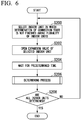
- Fig. 6 is a flowchart showing the flow of processing executed by the outdoor side control unit 28 of the second embodiment.
- the outdoor side control unit 28 selects an indoor unit 30, in which the determination of the connection state has not been completed, among the plurality of indoor units 30 (step S200).
- the outdoor side control unit 28 controls the expansion valve 18 of the indoor unit 30 selected in step S200 to the open state (step S202).
- the outdoor side control unit 28 controls the air conditioning system 1 to a standby state for a predetermined time (step S204).
- the outdoor side control unit 28 executes a determining process of the connection state (step S206). Since the determining process is the same as the processes from the steps S150 to S168 described in the first embodiment, a description thereof will be omitted.
- the outdoor side control unit 28 determines whether or not the connection state of all the indoor units 30 has been determined (step S208). If the connection state of all the indoor units 30 has not been determined, the process returns to step S200. When the connection state of all the indoor units 30 has been determined, the process of this flowchart ends. As a result, the processing executed by this flowchart ends.
- Fig. 7 is a diagram showing an overview of the check operation performed by the outdoor side control unit 28 according to the second embodiment.
- the indoor unit 30-1 having the room A as an air conditioning target space
- the indoor unit 30-2 having the room B as an air conditioning target space
- the indoor unit 30-3 having the room C as an air conditioning target will be described as being subjected to the check operation.
- the determining process is executed one by one in order from room A to room C.
- the outdoor side control unit 28 controls the compressor 12 to the ON state, and controls the expansion valve 18-1 for circulating the refrigerant in the indoor unit 30-1 to the predetermined open state.
- the outdoor side control unit 28 sets the compressor 12 to the OFF state, controls the expansion valve 18 of the indoor unit 30-2 of the next determination target to the predetermined open state and controls the other expansion valve 18 to the closed state.
- the determining process of the room B is executed, and after the lapse of the interval time, the determining process of the room C is executed.
- the fan 34 is controlled to the OFF state during the interval time.
- the outdoor side control unit 28 in order to maintain the fan 34 in the OFF state in the interval time, can perform the check operation, without making the person in the air conditioning target space feel that the check operation is performed.
- the outdoor side control unit 28 controls the expansion valve 18 for circulating the refrigerant to the indoor unit 30, which is the target of the determining process, to the open state, and controls the other expansion valve 18 to the closed state, thereby making it possible to execute the next determining process in a state in which the influence of the refrigerant remaining in the refrigerant pipe is reduced.
- the outdoor side control unit 28 determines whether the temperature difference ⁇ T is equal to or lower than the temperature T1 ( ⁇ T ⁇ T1) in step S152 of the determining process. Further, the outdoor side control unit 28 determines whether the temperature difference ⁇ Tn is equal to or lower than the temperature T2 ( ⁇ Tn ⁇ T2) in step S156 of the determining process. Further, the outdoor side control unit 28 determines whether the temperature TC is equal to or higher than the temperature TCn (TC ⁇ TCn) in step S162 of the determining process.
- the outdoor side control unit 28 performs the determination of step S152 (determination as to whether the temperature difference ⁇ T is equal to or higher than the temperature Tl), the determination of step S156 (determination as to whether the temperature difference ⁇ Tn is equal to or higher than the temperature T2 for all the other indoor units 30), and the determination of step S162 (determination as to whether the temperature TC is equal to or lower than the temperature TCn).
- the outdoor side control unit 28 may acquire one or more determination results from the above-described respective steps from another device, and determine whether at least one of the pipe and the communication line is correctly connected on the basis of the acquired determination result.
- the other device acquires the detection result of the indoor side heat exchanger temperature sensor 36 included in the indoor unit 30 and the detection result of the indoor side temperature sensor 38, performs one or more determinations among the respective steps on the basis of the acquired detection results, and transmits the determination result to the outdoor side control unit 28 via a network such as a local area network (LAN).
- a network such as a local area network (LAN).
- an outdoor unit having at least a compressor and connectable to a refrigerant pipe system
- a first indoor unit having a first heat exchanger and connectable to the refrigerant pipe system
- a second indoor unit having a second heat exchanger and connectable to the refrigerant pipe system
- a first temperature determination unit which is configured to determine the temperature of the first heat exchanger
- a second temperature determination unit which is configured to determine the temperature of the second heat exchanger
- a third temperature determination unit provided for the first indoor unit and configured to determine the temperature of an air conditioning target space associated with the first indoor unit
- a fourth temperature determination unit provided for the second indoor unit and configured to determine the temperature of an air conditioning target space associated with the second indoor unit
- a control unit configured to determine whether at least one of a first refrigerant pipe connected to the first indoor unit of the refrigerant pipe system connected to the first indoor unit and a first communication line connected to the first indoor unit is correctly connected, when a first temperature difference between the temperature determined by the first temperature determination
Landscapes
- Engineering & Computer Science (AREA)
- Chemical & Material Sciences (AREA)
- Combustion & Propulsion (AREA)
- Mechanical Engineering (AREA)
- General Engineering & Computer Science (AREA)
- Air Conditioning Control Device (AREA)
Abstract
Description
- Embodiments of the present invention relate to an air conditioning system.
- Priority is claimed on Japanese Patent Application No.
2015-221940, filed November 12, 2015 - Conventionally, an air conditioning system in which a plurality of indoor units are connected to one outdoor unit through a refrigerant pipe and a communication line is known. In this type of air conditioning system, in some cases, it is determined whether or not the connection between the pipe and the communication line is correct, on the basis of a change in the refrigerant temperature before and after supplying the refrigerant to the pipe which is acquired from a sensor that detects a refrigerant temperature via a heat exchanger.
- [Patent Document 1]
Japanese Unexamined Patent Application, First Publication No.H5-33982 - However, in this conventional air conditioning system, there is a case in which it is not possible to accurately determine whether the pipe or the communication line is correctly connected.
- An object to be solved by the present invention is to provide an air conditioning system capable of more accurately determining whether a pipe or a communication line is correctly connected.
- An air conditioning system according to an embodiment includes an outdoor unit, a first indoor unit, a second indoor unit, a first temperature determination unit, a second temperature determination unit, a third temperature determination unit, a fourth temperature determination unit, and a control unit. The outdoor unit has at least a compressor and is connectable to a refrigerant pipe system. The first indoor unit has a first heat exchanger and is connectable to the refrigerant pipe system. The second indoor unit has a second heat exchanger and is connectable to the refrigerant pipe system. The first temperature determination unit is configured to determine the temperature of the first heat exchanger. The second temperature determination unit is configured to determine the temperature of the second heat exchanger. The third temperature determination unit is provided for the first indoor unit and configured to determine the temperature of an air conditioning target space associated with the first indoor unit. The fourth temperature determination unit is provided for the second indoor unit and configured to determine the temperature of an air conditioning target space associated with the second indoor unit. The control unit configured to determine whether at least one of a first refrigerant pipe connected to the first indoor unit of the refrigerant pipe system connected to the first indoor unit and a first communication line connected to the first indoor unit is correctly connected, when a first temperature difference between the temperature determined by the first temperature determination unit and the temperature determined by the third temperature determination unit is equal to or higher than a first threshold value, and a second temperature difference between the temperature determined by the second temperature determination unit and the temperature determined by the fourth temperature determination unit is less than a second threshold value.
-
-
Fig. 1 is a diagram showing a configuration of anair conditioning system 1. -
Fig. 2 is a diagram showing a configuration of a control unit of theair conditioning system 1. -
Fig. 3 is a flowchart showing a flow of processing of a check operation executed by an outdoorside control unit 28. -
Fig. 4 is a diagram showing an overview of the check operation performed by the outdoorside control unit 28. -
Fig. 5 is a flowchart showing the flow of a determining process executed by the outdoorside control unit 28. -
Fig. 6 is a flowchart showing the flow of processing executed by the outdoorside control unit 28 according to a second embodiment. -
Fig. 7 is a diagram showing an overview of a check operation performed by an outdoorside control unit 28 according to the second embodiment. - Hereinafter, an air conditioning system of an embodiment will be described with reference to the drawings.
-
Fig. 1 is a diagram showing a configuration of anair conditioning system 1. Theair conditioning system 1 may include anoutdoor unit 10, and indoor units 30-1, 30-2, ... 30-n. Hereinafter, when the indoor units are not distinguished from other indoor units, they are simply referred to asindoor units 30. Theindoor units 30 are installed, for example, in different rooms. Theoutdoor unit 10 and each indoor unit 30-1 are connected to connection pipes 2-1-1, 2-1-2, ... 2-n-2. - The
outdoor unit 10 includes acompressor 12, anaccumulator 13, a four-way valve 14, an outdoorside heat exchanger 16, and expansion valves 18-1 to 18-n. - The
compressor 12 compresses the refrigerant and discharges the refrigerant to therefrigerant pipe 20 via the four-way valve 14. Thecompressor 12 circulates the refrigerant in the direction of an arrow in the drawing. The refrigerant is, for example, R410A, or R32. Further, the refrigerant may be a refrigerant containing 50% or more of R32. In the drawings, white arrows indicate the flow of the refrigerant at the time of cooling, and black arrows indicate the flow of the refrigerant at the time of heating. In the present embodiment, as an example, the operation during cooling of theair conditioning system 1 will be mainly described. Theaccumulator 13 is provided to be adjacent to thecompressor 12. Theaccumulator 13 separates the refrigerant returning to thecompressor 12 into a gas-phase refrigerant and a liquid-phase refrigerant. - The four-
way valve 14 switches the direction in which the refrigerant discharged from thecompressor 12 is circulated. The four-way valve 14 switches between a state in which thecompressor 12 and the outdoorside heat exchanger 16 are electrically connected to each other, and a state in which thecompressor 12 and the indoorside heat exchanger 32 are electrically connected to each other. For example, the four-way valve 14 may circulate the refrigerant discharged from thecompressor 12 to the outdoorside heat exchanger 16. Further, the four-way valve 14 circulates the refrigerant discharged from thecompressor 12 to the connection pipes 2-1-1 and 2-n-1. - The four-
way valve 14, the outdoorside heat exchanger 16, and the expansion valves 18-1 to 18-n are connected to each other via therefrigerant pipes expansion valves 18. The outdoorside heat exchanger 16 liquefies the refrigerant discharged from thecompressor 12 and releases the heat contained in the refrigerant. Theexpansion valve 18 is connected to theindoor unit 30 via theconnection pipe 2. Theexpansion valve 18 sets the temperature of the liquid refrigerant to low and sets the pressure of the liquid refrigerant to low, by controlling the pressure reduction and the flow rate of the refrigerant which has become the liquid discharged from the outdoorside heat exchanger 16. - The
indoor unit 30 includes an indoorside heat exchanger 32, afan 34, an indoor side heatexchanger temperature sensor 36, and an indoorside temperature sensor 38. The indoorside heat exchanger 32 performs heat-exchange between the refrigerant discharged from theexpansion valve 18 and air to evaporate the refrigerant. Thefan 34 blows the air having undergone heat exchange via the indoorside heat exchanger 32 to an air conditioning target space The indoor side heatexchanger temperature sensor 36 determines the temperature of the indoorside heat exchanger 32. The indoorside temperature sensor 38 determines the temperature of the room in which theindoor unit 30 is installed. -
Fig. 2 is a diagram showing a configuration of a control unit of theair conditioning system 1. In addition to the configuration described inFig. 1 , theair conditioning system 1 further includes an outdoorside operation unit 26, an outdoorside control unit 28, an indoorside operation unit 40, and an indoorside control unit 42. The outdoorside control unit 28 and the indoorside control unit 42 are connected to each other through a communication line and an electrical line. - The outdoor
side control unit 28 or the indoorside control unit 42 is, for example, a processor such as a central processing unit (CPU). In addition, the outdoorside control unit 28 or the indoorside control unit 42 may be hardware such as a large scale integration (LSI) or an application specific integrated circuit (ASIC). - The outdoor
side operation unit 26 includes a mode switching button, a display unit, and the like. The outdoorside operation unit 26 supplies a signal corresponding to the operation of the user to the outdoorside control unit 28. When the check operation is instructed, the outdoorside operation unit 26 supplies a signal indicating that the instruction for the check operation has been given to the outdoorside control unit 28. The check operation is an operation of determining whether or not the pipe and the communication line between theoutdoor unit 10 and theindoor unit 30 are connected normally (correctly)(details will be described later). Further, the display unit of the outdoorside operation unit 26 displays the results of the check operation or information indicating the abnormality of anair conditioning system 1. - Indoor
side operation units 40 are provided to correspond to each of the plurality ofindoor units 30. The indoorside operation unit 40 includes a setting temperature changing button of an air conditioning target space of theindoor unit 30, an operation mode switching button, an indoor side display unit, and the like. The indoorside operation unit 40 supplies a signal corresponding to the user's operation to the indoorside control unit 42. The display unit of the indoorside operation unit 40 displays the operation state of theindoor unit 30, the state of the air conditioning target space, the set operation mode, and the like. - The outdoor
side control unit 28 controls the driving of thecompressor 12. The outdoorside control unit 28 controls an opening degree of the valve of theexpansion valve 18. The outdoorside control unit 28 generates an instruction signal, on the basis of the signal supplied from the indoorside operation unit 40 or information acquired from the indoorside control unit 42. The outdoorside control unit 28 supplies instruction signals to thecompressor 12, theexpansion valve 18, the outdoorside operation unit 26, and the indoorside control unit 42. Details of processes of the outdoorside control unit 28 will be described later. - Indoor
side control units 42 are provided to correspond to each of the plurality ofindoor units 30. The indoorside control unit 42 controls each unit included in theindoor unit 30 on the basis of an instruction signal supplied from the outdoorside control unit 28. The indoorside control unit 42 supplies information or signals acquired from the indoor side heatexchanger temperature sensor 36, the indoorside temperature sensor 38, and the indoorside operation unit 40 to the outdoorside control unit 28. -
Fig. 3 is a flowchart showing the flow of a check operation (determination of whether or not the connection of the pipe or the communication line is normal) executed by the outdoorside control unit 28. First, the outdoorside control unit 28 selects anindoor unit 30 in which the determination of the connection state has not been completed, among the plurality of indoor units 30 (step S100). - The outdoor
side control unit 28 controls thefan 34 of theindoor unit 30 selected in step S100 in an ON state (step S102), and controls theexpansion valves 18 of all theindoor units 30 in an open state (step S104). The outdoorside control unit 28 controls theair conditioning system 1 in a standby state for a predetermined time (step S106). Next, the outdoorside control unit 28 executes a determining process of the connection state (step S108). Details of the determining process will be described later. - Next, the outdoor
side control unit 28 determines whether or not the connection state of all theindoor units 30 has been determined (step S110). When the connection state of all theindoor units 30 has not been determined, the process returns to step S100. When the connection state of all theindoor units 30 has been determined, the process of the flowchart ends. -
Fig. 4 is a diagram showing an overview of the check operation performed by the outdoorside control unit 28. For example, an indoor unit 30-1 having a room A as an air conditioning target space, an indoor unit 30-2 having a room B as an air conditioning target space, and an indoor unit 30-3 having a room C as an air conditioning target space will be described as being subjected to the check operation. Also, it is assumed that the determining process is executed one by one in order from the room A to the room C. In the shown example, the temperature change (TC-A to TC-C in the drawings) of the indoorside heat exchanger 32 in the chambers A and C from the start to the end of the check operation is shown. In addition, the open and closed states (PMV A to PMV C in the drawings) of theexpansion valve 18 which circulates the refrigerant in the chambers A and C for each time, and the operation state of thecompressor 12 for each time are shown. - First, the outdoor
side control unit 28 controls thecompressor 12 in an ON state, and controls theexpansion valve 18, which circulates the refrigerant in the indoor unit 30-1, in a predetermined open state. The outdoorside control unit 28 executes the determining process of the room A, and when the determining process of the room A ends, the outdoorside control unit 28 sets thecompressor 12 to an OFF state and controls at least thefan 34 of the indoor unit 30-2 to the ON state. Here, thefans 34 of all the indoor units 30-1 and 30-3 may be controlled to the ON state. Further, the outdoorside control unit 28 controls theexpansion valves 18 of the indoor units 30-1 and 30-3 to the open state. These states are maintained for a predetermined time. Hereinafter, the interval time indicates the time for maintaining thecompressor 12 is in the OFF state, maintaining at least thefan 34 of theindoor unit 30 as being subjected to the determining process of the connected state next is in the ON state, and maintaining all theexpansion valves 18 is in the open state for the predetermined time - The interval time is, for example, the time which is set for returning from the lowered temperature, on the assumption that the temperature of the indoor
side heat exchanger 32 of the indoor unit 30-2, which becomes the target of the determining process of the connection state next, is lowered during the determining process of the indoor unit 30-1 which is the target of the immediately preceding determining process. The interval time may be a preset time. Further, the interval time may be a time determined by the outdoorside control unit 28 on the basis of the detection results of the indoor side heatexchanger temperature sensor 36 or the indoorside temperature sensor 38. - By controlling the
fan 34 to the ON state during the interval time, the temperature of the indoorside heat exchanger 32 of theindoor unit 30 or the air conditioning target space is easily returned to that of a state before the determining process of the connection state was started. Further, by controlling theexpansion valves 18 of the indoor units 30-1 to 30-3 to the open state, it is possible to suppress the temperature change or the like occurring in theindoor unit 30 connected to the part other than the pipe in which the refrigerant is circulated by the residual refrigerant in the pipe or the pressure change in the pipe. - After elapse of the interval time, the determining process of the connection state of the room B is executed, and after the interval time has elapsed, the determining process of the connection state of the room C is executed. Thus, it is determined whether or not the pipe of the
indoor unit 30 connected to theoutdoor unit 10 and the communication line are connected normally. - In the
air conditioning system 1 of the embodiment, an indoor side expansion valve may be further provided between theconnection pipe 2 of theindoor unit 30 and the indoorside heat exchanger 32, in addition to theexpansion valve 18. In this case, when the determining process of the connection state is executed, an indoor side expansion valve different from the indoor side expansion valve included in theindoor unit 30 subject to the determining process may be controlled to the closed state. Thus, it is possible to reduce the influence of residual refrigerant and pressure change occurring in theindoor unit 30 other than the determination target through the determining process of the connection state. -
Fig. 5 is a flowchart showing the flow of a determining process executed by the outdoorside control unit 28. First, the outdoorside control unit 28 controls thecompressor 12 for the ON state and controls the expansion valve 18-1 of the indoor unit 30-1, which is a determination target of the connection state, to the predetermined open state (step S150). Here, the indoor unit 30-1, which is a determination target for the connection state, corresponds to the "first indoor unit" in the claims, and the indoor units 30-2 and 30-3 which are not determination targets of the connection state correspond to "an indoor unit other than the first indoor unit" in the claims. The indoor side heat exchanger 32-1 corresponds to the "first heat exchanger" in the claims, the indoor side heat exchanger temperature sensor 36-1 corresponds to the "first temperature determination unit," and the indoor side temperature sensor 38-1 corresponds to the "third temperature determination unit" in the claims. The indoor side heat exchangers 32-2 and 32-3 correspond to the "second heat exchanger" in the claims, the indoor side heat exchanger temperature sensors 36-2 and 36-3 correspond to the "second temperature determination unit," and the indoor side temperature sensors 38-2 and 38-3 correspond to the "fourth temperature determination unit" in the claims. - The rotational speed of the
compressor 12 is, for example, 25% or less of the maximum rotational speed of thecompressor 12. By suppressing the rotational speed of thecompressor 12, it is possible to suppress the amount of refrigerant liquid returning to theaccumulator 13 during the check operation, and it is possible to reduce the load applied to thecompressor 12. The opening degree of the expansion valve 18-1 is, for example, 25% or less of the maximum flow opening degree of theexpansion valve 18. By setting the opening degree of the expansion valve 18-1 to 25% or less, the decrease in the temperature of the indoorside3 heat exchanger 32 of the indoor unit 30-1 which is the determination target becomes gentle, and it is possible to suppress an increase in processing time. - Next, the outdoor
side control unit 28 determines whether or not a temperature difference ΔT is equal to or higher than a temperature T1 (step S152). The temperature difference ΔT is a difference between the temperature TA detected by the indoor side temperature sensor 38-1 of the indoor unit 30-1 on which determination is to be performed and the temperature TC detected by the indoor side heat exchanger temperature sensor 36-1 of the indoor unit 30-1 on which determination is to be performed. - When the temperature difference ΔT is not equal to or higher than the temperature T1, the outdoor
side control unit 28 determines whether or not a predetermined time has elapsed (step S154). When the predetermined time has not elapsed, the process of step S152 is repeated. When the predetermined time has elapsed, the outdoorside control unit 28 determines that there is a possibility that an abnormality may exist in the connection state of the pipe and the communication line of the indoor unit 30-1 on which determination is to be performed (step S166). This is because the temperature determined by the indoor side heat exchanger temperature sensor 36-1 has not decreased by more than a predetermined temperature even though the refrigerant is circulated in the indoor unit 30-1 on which determination is to be performed. In this case, the outdoorside control unit 28 and the communication line with the indoorside control unit 42 are misconnected, and there is a possibility that a difference may occur between the indoorside control unit 42 to be controlled and the indoorside control unit 42 that is actually controlled. In addition, the pipe between the indoor unit 30-1 and theoutdoor unit 10 is erroneously connected, and there is a possibility that a difference may occur between the indoor unit 30-1 of the target through which the refrigerant is circulated and theindoor unit 30 in which the refrigerant is actually circulated. - When the temperature difference ΔT is equal to or higher than the temperature T1, the outdoor
side control unit 28 determines whether or not the temperature difference ΔTn is equal to or higher than the temperature T2 for all the other indoor units 30 (step S156). The temperature difference ΔTn is a difference between the temperature TAn detected by the indoorside temperature sensor 38 of theindoor unit 30 which is not the determination target for the connection state and the temperature TCn detected by the indoor side heatexchanger temperature sensor 36 of theindoor unit 30 which is not the determination target for the connection state. In the case in which there are a plurality ofindoor units 30 which are not the determination targets, the outdoorside control unit 28 calculates the temperature difference ΔTn between the temperature TAn detected by the indoorside temperature sensor 38 provided in each of theindoor units 30 which are not the determination targets and the temperature TCn detected by the indoor side heatexchanger temperature sensor 36 provided in each of theindoor units 30 which are not the determination targets. The outdoorside control unit 28 determines whether or not all the calculated temperature differences ΔTn are equal to or higher than the temperature T2. When any one of the calculated temperature differences ΔTn is equal to or higher than the temperature T2, the process proceeds to step S160. When all the calculated temperature differences ΔTn are not equal to or higher than the temperature T2, the process proceeds to step S158. - When all the temperature differences ΔTn are not equal to or higher than the temperature T2, the outdoor
side control unit 28 determines that the indoor unit 30-1 is connected to theoutdoor unit 10 normally (step S158). In this case, the outdoorside control unit 28 controls thecompressor 12 to the OFF state (step S168). This is because since the temperature determined by the indoor side heatexchanger temperature sensor 36, which is not the determination target, is not lowered by the temperature T2 or more, it is presumed that the refrigerant is not circulated in theindoor unit 30 that is not the determination target. For example, the temperature T2 may be lower than the temperature T1. - When any one of the calculated temperature differences ΔTn is equal to or higher than the temperature T2, the outdoor
side control unit 28 waits until a predetermined time elapses (step S160). When the predetermined time has elapsed, the outdoorside control unit 28 determines whether or not the temperature TC is equal to or lower than the temperature TCn (step S162). When there are a plurality ofindoor units 30 which are not the determination targets, the outdoorside control unit 28 compares the temperature TC detected by the indoor side heatexchanger temperature sensor 36 of the indoor unit 30-1 on which determination is to be performed with the temperature TCn detected by the indoor side heatexchanger temperature sensor 36 provided in each of theindoor units 30 which are not the determination target. If the temperature TC is equal to or lower than all the other temperatures TCn, the process proceeds to step S164. If the temperature TC is not equal to or lower than one temperature of all the temperatures TCn, the process proceeds to step S166. - When the temperature TC is not equal to or lower than the temperature TCn, the outdoor
side control unit 28 determines that there is a possibility that an abnormality may exist in the connection state of the pipe and the communication line of the indoor unit 30-1 on which determination is to be performed (step S166), and the process proceeds to S168. When the temperature TC is equal to or lower than the temperature TCn, the outdoorside control unit 28 determines that the indoor unit 30-1 on which determination is to be performed is connected to theoutdoor unit 10 normally (step S164), and controls thecompressor 12 to a turned-off state (step S168). In this case, a temperature difference equal to or greater than the predetermined temperature occurs between the temperature of the indoorside temperature sensor 38 of theindoor unit 30 which is not the determination target and the temperature of the indoor side heatexchanger temperature sensor 36 of theindoor unit 30 which is not the determination target. However, since the temperature of the indoor side temperature sensor 38-1 of the indoor unit 30-1 on which determination is to be performed is lower than the temperature of the indoorside temperature sensor 38 of the otherindoor unit 30, the refrigerant is presumed to circulate to the indoor unit 30-1 on which determination is to be performed. As a result, the processing of this flowchart ends. - When the determining process of one indoor unit 30-1 is completed as described above, for example, the determining process of the next indoor unit 30-2 is executed. In the determining process of the next indoor unit 30-2, the indoor unit 30-1, which is determined to be connected to the
outdoor unit 10 normally, is excluded from the comparison target in the determining process. For example, in the process of determining whether or not the temperature difference ΔTn in step S156 is equal to or higher than the temperature T2 and in the process of determining whether or not the temperature TC in step S162 is equal to or lower than the temperature TCn, the indoor unit 30-1 determined to be normally connected to theoutdoor unit 10 is excluded from comparison. On the other hand, if it is determined that there is a possibility that an abnormality may exist in the connection state of the pipe and the communication line between theoutdoor unit 10 and the indoor unit 30-1, the indoor unit 30-1 is included in the comparison targets, in the process of determining that the temperature difference ΔTn in step S156 is equal to or higher than the temperature T2 and the process of determining whether or not the temperature TC in step S162 is equal to or lower than the temperature TCn. - Further, when the determining process of the connection state is executed for all the
indoor units 30, and the check operation is completed, the outdoorside control unit 28 displays the results of the check operation on the display unit of the outdoorside operation unit 26. For example, information indicating the presence or absence of theindoor units 30 that may not be connected to theoutdoor unit 10 normally is displayed on the display unit of the outdoorside operation unit 26. Further, identification information of theindoor unit 30 that is not connected to theoutdoor unit 10 normally is displayed on the display unit of the outdoorside operation unit 26. - Meanwhile, there is a case where it is determined whether the connection of the pipe and the signal line between the indoor unit and the outdoor unit is normal on the basis of the temperature change of the indoor side heat exchanger. In this case, due to the influence of the refrigerant remaining in the indoor side heat exchanger, the temperature of the indoor side heat exchanger through which the refrigerant does not flow may also change, and there is a case in which it is not possible to more accurately determine whether the connection of the pipe and the communication line between the
outdoor unit 10 and theindoor unit 30 is normal. - In contrast, in the
air conditioning system 1 of the present embodiment, even if there is a residual refrigerant by the above-described determining process and there is a temperature change in theindoor unit 30 and the air conditioning target space different from the target of the determining process, it is possible to more accurately determine whether the connection of the pipe and the communication line between theoutdoor unit 10 and theindoor unit 30 is normal. Furthermore, in theair conditioning system 1 of the present embodiment, since the determining process is performed in a state in which the temperature of the indoorside heat exchanger 32 of theindoor unit 30 is maintained at a predetermined level or higher, it is possible to more accurately determine whether the connection of the pipe and the communication line between theoutdoor unit 10 and theindoor unit 30 is normal. - According to the first embodiment described above, the outdoor
side control unit 28 determines that the connection state of the refrigerant pipe or the communication line connected to theindoor unit 30 which is the determination target is normal, when the temperature difference ΔT of theindoor unit 30, which is the determination target for the connection state, is equal to or higher than the temperature T1, and the temperature difference ΔTn of the indoorside control unit 30 which is not the determination target is not equal to or higher than the temperature T2. Further, even when the temperature difference ΔTn of theindoor unit 30, which is not the determination target for the connection state, is equal to or higher than the temperature T2, the outdoorside control unit 28 determines that the connection state of the refrigerant pipe or the communication line connected to theindoor unit 30 on which determination is to be performed is normal, when the temperature TC is equal to or lower than the temperature TCn after a lapse of a predetermined time. As a result, theair conditioning system 1 can more accurately determine whether the connection of the pipe or the communication line between theoutdoor unit 10 and theindoor unit 30 is normal. - A second embodiment will be described below. Here, differences from the first embodiment will be mainly described, and the description of the functions and the like common with the first embodiment will be omitted. In the first embodiment, in the interval time, the
fan 34 is maintained in the ON state and all theexpansion valves 18 are controlled to the open state. In contrast, in the second embodiment, in the interval time, thefan 34 is maintained in the OFF state, theexpansion valve 18 for circulating the refrigerant to theindoor unit 30 subject to the determining process is controlled to the open state, and theother expansion valve 18 is controlled to the closed state. Hereinafter, differences from the first embodiment will be mainly described. -
Fig. 6 is a flowchart showing the flow of processing executed by the outdoorside control unit 28 of the second embodiment. First, the outdoorside control unit 28 selects anindoor unit 30, in which the determination of the connection state has not been completed, among the plurality of indoor units 30 (step S200). - The outdoor
side control unit 28 controls theexpansion valve 18 of theindoor unit 30 selected in step S200 to the open state (step S202). The outdoorside control unit 28 controls theair conditioning system 1 to a standby state for a predetermined time (step S204). Next, the outdoorside control unit 28 executes a determining process of the connection state (step S206). Since the determining process is the same as the processes from the steps S150 to S168 described in the first embodiment, a description thereof will be omitted. - Next, the outdoor
side control unit 28 determines whether or not the connection state of all theindoor units 30 has been determined (step S208). If the connection state of all theindoor units 30 has not been determined, the process returns to step S200. When the connection state of all theindoor units 30 has been determined, the process of this flowchart ends. As a result, the processing executed by this flowchart ends. -
Fig. 7 is a diagram showing an overview of the check operation performed by the outdoorside control unit 28 according to the second embodiment. For example, the indoor unit 30-1 having the room A as an air conditioning target space, the indoor unit 30-2 having the room B as an air conditioning target space, and the indoor unit 30-3 having the room C as an air conditioning target will be described as being subjected to the check operation. Also, it is assumed that the determining process is executed one by one in order from room A to room C. - First, the outdoor
side control unit 28 controls thecompressor 12 to the ON state, and controls the expansion valve 18-1 for circulating the refrigerant in the indoor unit 30-1 to the predetermined open state. When the determining process of the room A is completed, the outdoorside control unit 28 sets thecompressor 12 to the OFF state, controls theexpansion valve 18 of the indoor unit 30-2 of the next determination target to the predetermined open state and controls theother expansion valve 18 to the closed state. After the lapse of the interval time, the determining process of the room B is executed, and after the lapse of the interval time, the determining process of the room C is executed. In the second embodiment, thefan 34 is controlled to the OFF state during the interval time. Thus, it is possible to execute the check operation, without making the user in the room subjected to the determining process feel that the check operation is performed. - According to the second embodiment described above, in order to maintain the
fan 34 in the OFF state in the interval time, the outdoorside control unit 28 can perform the check operation, without making the person in the air conditioning target space feel that the check operation is performed. In addition, the outdoorside control unit 28 controls theexpansion valve 18 for circulating the refrigerant to theindoor unit 30, which is the target of the determining process, to the open state, and controls theother expansion valve 18 to the closed state, thereby making it possible to execute the next determining process in a state in which the influence of the refrigerant remaining in the refrigerant pipe is reduced. - In the
air conditioning system 1 according to the first embodiment and the second embodiment, the determining process at the time of the cooling operation has been described, but the first embodiment and the second embodiment are also applied at the time of the heating operation. In this case, the outdoorside control unit 28 determines whether the temperature difference ΔT is equal to or lower than the temperature T1 (ΔT ≤ T1) in step S152 of the determining process. Further, the outdoorside control unit 28 determines whether the temperature difference ΔTn is equal to or lower than the temperature T2 (ΔTn ≤ T2) in step S156 of the determining process. Further, the outdoorside control unit 28 determines whether the temperature TC is equal to or higher than the temperature TCn (TC ≥ TCn) in step S162 of the determining process. - In addition, in the
air conditioning system 1 according to the first embodiment and the second embodiment, the description has been given of a case where the outdoorside control unit 28 performs the determination of step S152 (determination as to whether the temperature difference ΔT is equal to or higher than the temperature Tl), the determination of step S156 (determination as to whether the temperature difference ΔTn is equal to or higher than the temperature T2 for all the other indoor units 30), and the determination of step S162 (determination as to whether the temperature TC is equal to or lower than the temperature TCn). However, the outdoorside control unit 28 may acquire one or more determination results from the above-described respective steps from another device, and determine whether at least one of the pipe and the communication line is correctly connected on the basis of the acquired determination result. In this case, the other device acquires the detection result of the indoor side heatexchanger temperature sensor 36 included in theindoor unit 30 and the detection result of the indoorside temperature sensor 38, performs one or more determinations among the respective steps on the basis of the acquired detection results, and transmits the determination result to the outdoorside control unit 28 via a network such as a local area network (LAN). - According to at least one embodiment described above, by including an outdoor unit having at least a compressor and connectable to a refrigerant pipe system, a first indoor unit having a first heat exchanger and connectable to the refrigerant pipe system, a second indoor unit having a second heat exchanger and connectable to the refrigerant pipe system, a first temperature determination unit which is configured to determine the temperature of the first heat exchanger, a second temperature determination unit which is configured to determine the temperature of the second heat exchanger, a third temperature determination unit provided for the first indoor unit and configured to determine the temperature of an air conditioning target space associated with the first indoor unit, a fourth temperature determination unit provided for the second indoor unit and configured to determine the temperature of an air conditioning target space associated with the second indoor unit, and a control unit configured to determine whether at least one of a first refrigerant pipe connected to the first indoor unit of the refrigerant pipe system connected to the first indoor unit and a first communication line connected to the first indoor unit is correctly connected, when a first temperature difference between the temperature determined by the first temperature determination unit and the temperature determined by the third temperature determination unit is equal to or higher than a first threshold value, and a second temperature difference between the temperature determined by the second temperature determination unit and the temperature determined by the fourth temperature determination unit is less than a second threshold value, it is possible to determine whether the pipe or the connection pipe is correctly connected.
- While several embodiments of the present invention have been described, these embodiments have been presented by way of example and are not intended to limit the scope of the invention. These embodiments can be implemented in various other forms, and various omissions, replacements, and modifications can be made without departing from the gist of the invention. These embodiments and modifications thereof are included in the scope and gist of the invention, as well as within the scope of the invention described in the claims and their equivalents.
Claims (10)
- An air conditioning system comprising:an outdoor unit having at least a compressor and connectable to a refrigerant pipe system;a first indoor unit having a first heat exchanger and connectable to the refrigerant pipe system;a second indoor unit having a second heat exchanger and connectable to the refrigerant pipe system;a first temperature determination unit configured to determine the temperature of the first heat exchanger;a second temperature determination unit configured to determine the temperature of the second heat exchanger;a third temperature determination unit provided for the first indoor unit and configured to determine the temperature of an air conditioning target space associated with the first indoor unit;a fourth temperature determination unit provided for the second indoor unit and configured to determine the temperature of an air conditioning target space associated with the second indoor unit; anda control unit configured to determine whether at least one of a first refrigerant pipe connected to the first indoor unit of the refrigerant pipe system connected to the first indoor unit and a first communication line connected to the first indoor unit is correctly connected, when a first temperature difference between the temperature determined by the first temperature determination unit and the temperature determined by the third temperature determination unit is equal to or higher than a first threshold value, and a second temperature difference between the temperature determined by the second temperature determination unit and the temperature determined by the fourth temperature determination unit is less than a second threshold value.
- The air conditioning system according to claim 1,
wherein the control unit is configured to determine whether the first temperature difference between the temperature determined by the first temperature determination unit and the temperature determined by the third temperature determination unit is equal to or higher than the first threshold value, and is configured to determine whether the second temperature difference between the temperature determined by the second temperature determination unit and the temperature determined by the fourth temperature determination unit is less than the second threshold value. - The air conditioning system according to claim 1,
wherein, when the first temperature difference is equal to or higher than the first threshold value until a predetermined time has elapsed after the first temperature difference is determined to be less than the first threshold value, if the second temperature difference is less than the second threshold value, the control unit is configured to determine that at least one of the first refrigerant pipe of the refrigerant pipe system connected to the first indoor unit and the first communication line connected to the first indoor unit is correctly connected. - The air conditioning system according to claim 3,
wherein, when the first temperature difference is equal to or higher than the first threshold value and the second temperature difference is equal to or higher than the second threshold value, after the lapse of a predetermined time from the determination, when the temperature determined by the first temperature determination unit provided corresponding to the first indoor unit is equal to or less than the temperature determined by the second temperature determination unit provided corresponding to the second indoor unit, the control unit is configured to determine that at least one of the first refrigerant pipe and the first communication line is correctly connected. - The air conditioning system according to claim 4,
wherein the control unit is configured to determine whether at least one of a second refrigerant pipe of the refrigerant pipe system connected to the second indoor unit and a second communication line connected to the second indoor unit is correctly connected after performing the determination on the first indoor unit. - The air conditioning system according to claim 1, further comprising:a third indoor unit having a third heat exchanger and connectable to the refrigerant pipe system;a fifth temperature determination unit configured to determine the temperature of the third heat exchanger; anda sixth temperature determination unit provided for the third indoor unit and configured to determine the temperature of an air conditioning target space associated with the third indoor unit,wherein, when it is determined that at least one of the first refrigerant pipe and the first communication line connected to the first indoor unit is correctly connected,in a case where a third temperature difference between the temperature determined by the second temperature determination unit and the temperature determined by the fourth temperature determination unit is equal to or higher than the first threshold value, and a fourth temperature difference between the temperature determined by the fifth temperature determination unit and the temperature determined by the sixth temperature determination unit is less than the second threshold value, the control unit is configured to determine that at least one of the second refrigerant pipe of the refrigerant pipe system connected to the second indoor unit and the second communication line connected to the second indoor unit connected to the second indoor unit is correctly connected.
- The air conditioning system according to claim 1,
wherein, when it is determined that at least one of the first refrigerant pipe and the first communication line is correctly connected, the control unit does not use the temperature determined by the first temperature determination unit and the temperature determined by the third first temperature determination unit, when determining whether least one of the second refrigerant pipe connected to the second indoor unit and the second communication line connected to the second indoor unit is correctly connected. - The air conditioning system according to claim 5,
wherein the control unit is configured to determine whether at least one of the first refrigerant pipe connected to the first indoor unit and the first communication line connected to the first indoor unit is correctly connected, after performing determination for the first indoor unit, waits for a predetermined time after the determination, and is configured to determine whether at least one of the second refrigerant pipe and the second communication line is correctly connected. - The air conditioning system according to claim 1,wherein the first indoor unit includes a first fan is configured to blow the air having undergone heat exchange via the first heat exchanger to the air conditioning target space associated with the first indoor unit,the second indoor unit includes a second fan is configured to blow the air having undergone heat exchange via the second heat exchanger to the air conditioning target space associated with the second indoor unit, andthe control unit is configured to control at least the second fan to an ON state, while waiting for a predetermined time after determining the first indoor unit.
- The air conditioning system according to claim 1, further comprising:a first expansion valve provided between the compressor and the first heat exchanger and configured to control a flow rate at which a refrigerant discharged from the compressor flows to the first heat exchanger; anda second expansion valve provided between the compressor and the second heat exchanger and configured to control a flow rate at which the refrigerant discharged from the compressor flows to the second heat exchanger,wherein the control unit is configured to control the first expansion valve and the second expansion valve to an open state, while waiting for a predetermined time after determining the first indoor unit.
Applications Claiming Priority (2)
| Application Number | Priority Date | Filing Date | Title |
|---|---|---|---|
| JP2015221940 | 2015-11-12 | ||
| PCT/JP2016/083368 WO2017082346A1 (en) | 2015-11-12 | 2016-11-10 | Air conditioning system |
Publications (3)
| Publication Number | Publication Date |
|---|---|
| EP3376126A1 true EP3376126A1 (en) | 2018-09-19 |
| EP3376126A4 EP3376126A4 (en) | 2019-06-19 |
| EP3376126B1 EP3376126B1 (en) | 2023-09-13 |
Family
ID=58696118
Family Applications (1)
| Application Number | Title | Priority Date | Filing Date |
|---|---|---|---|
| EP16864307.0A Active EP3376126B1 (en) | 2015-11-12 | 2016-11-10 | Air conditioning system |
Country Status (2)
| Country | Link |
|---|---|
| EP (1) | EP3376126B1 (en) |
| WO (1) | WO2017082346A1 (en) |
Families Citing this family (3)
| Publication number | Priority date | Publication date | Assignee | Title |
|---|---|---|---|---|
| JP7098057B2 (en) * | 2019-05-28 | 2022-07-08 | 三菱電機株式会社 | Control device and control method |
| CN115751607B (en) * | 2022-11-30 | 2024-11-19 | 珠海格力电器股份有限公司 | Detection method and device for air conditioner connecting pipe, air conditioner and storage medium |
| WO2024261926A1 (en) * | 2023-06-21 | 2024-12-26 | 三菱電機株式会社 | Air conditioning device |
Family Cites Families (6)
| Publication number | Priority date | Publication date | Assignee | Title |
|---|---|---|---|---|
| JP3152006B2 (en) * | 1993-04-14 | 2001-04-03 | ダイキン工業株式会社 | Anti-freezing device for air conditioners |
| JP3216435B2 (en) * | 1994-09-01 | 2001-10-09 | ダイキン工業株式会社 | Multi type air conditioner |
| JP2002147824A (en) * | 2000-11-14 | 2002-05-22 | Hitachi Ltd | Air conditioner |
| JP5865103B2 (en) * | 2012-02-07 | 2016-02-17 | 三菱電機株式会社 | Air conditioner |
| JP5858824B2 (en) * | 2012-03-01 | 2016-02-10 | 三菱電機株式会社 | Multi-type air conditioner |
| JP2014074533A (en) * | 2012-10-04 | 2014-04-24 | Panasonic Corp | Multi-type air conditioner |
-
2016
- 2016-11-10 WO PCT/JP2016/083368 patent/WO2017082346A1/en not_active Ceased
- 2016-11-10 EP EP16864307.0A patent/EP3376126B1/en active Active
Also Published As
| Publication number | Publication date |
|---|---|
| EP3376126A4 (en) | 2019-06-19 |
| EP3376126B1 (en) | 2023-09-13 |
| WO2017082346A1 (en) | 2017-05-18 |
Similar Documents
| Publication | Publication Date | Title |
|---|---|---|
| CN107003038B (en) | Apparatus and method for mixing water heating and air cooling and their control | |
| EP2873932B1 (en) | Hot and cold water air conditioning system | |
| EP2400234B1 (en) | Use-side unit and air conditioner | |
| JP6338761B2 (en) | Air conditioning system | |
| EP2950017B1 (en) | Water heating apparatus | |
| EP3376126B1 (en) | Air conditioning system | |
| CN107588513B (en) | Air conditioning system, control method and control device of air conditioning system | |
| EP3296656A1 (en) | Air conditioning system, control method, and program | |
| US20120216555A1 (en) | Mediating apparatus and air conditioning system | |
| CN106813360B (en) | Multi-connection system and its indoor unit's anti-cold air control method and device | |
| EP3208549B1 (en) | Air conditioner | |
| US11255560B2 (en) | Air-conditioning apparatus and method of determining operation condition | |
| US11525599B2 (en) | Controller of air conditioning apparatus, outdoor unit, relay unit, heat source unit, and air conditioning apparatus | |
| WO2020245986A1 (en) | Air conditioning ventilation system, device for controlling air conditioning ventilation system, and method for controlling air conditioning ventilation system | |
| EP3385642A1 (en) | Exhaust heat recovery system | |
| EP2472188A2 (en) | Heat pump interoperating hot water feeding apparatus | |
| EP2363659A1 (en) | Radiator | |
| US11397035B2 (en) | Controller of air conditioning apparatus, outdoor unit, relay unit, heat source unit, and air conditioning apparatus | |
| EP2375179B1 (en) | Radiator | |
| EP3159613B1 (en) | Heat pump heating system | |
| JPH11237097A (en) | Multi-room air conditioner | |
| EP3587946B1 (en) | Air conditioner | |
| JP3833497B2 (en) | Air conditioner | |
| US20190070932A1 (en) | Liquid heating device | |
| WO2017104086A1 (en) | Air conditioner |
Legal Events
| Date | Code | Title | Description |
|---|---|---|---|
| STAA | Information on the status of an ep patent application or granted ep patent |
Free format text: STATUS: THE INTERNATIONAL PUBLICATION HAS BEEN MADE |
|
| PUAI | Public reference made under article 153(3) epc to a published international application that has entered the european phase |
Free format text: ORIGINAL CODE: 0009012 |
|
| STAA | Information on the status of an ep patent application or granted ep patent |
Free format text: STATUS: REQUEST FOR EXAMINATION WAS MADE |
|
| 17P | Request for examination filed |
Effective date: 20180608 |
|
| AK | Designated contracting states |
Kind code of ref document: A1 Designated state(s): AL AT BE BG CH CY CZ DE DK EE ES FI FR GB GR HR HU IE IS IT LI LT LU LV MC MK MT NL NO PL PT RO RS SE SI SK SM TR |
|
| AX | Request for extension of the european patent |
Extension state: BA ME |
|
| DAV | Request for validation of the european patent (deleted) | ||
| DAX | Request for extension of the european patent (deleted) | ||
| REG | Reference to a national code |
Ref country code: DE Ref legal event code: R079 Free format text: PREVIOUS MAIN CLASS: F24F0011020000 Ipc: F24F0011490000 Ref country code: DE Ref legal event code: R079 Ref document number: 602016082800 Country of ref document: DE Free format text: PREVIOUS MAIN CLASS: F24F0011020000 Ipc: F24F0011490000 |
|
| A4 | Supplementary search report drawn up and despatched |
Effective date: 20190516 |
|
| RIC1 | Information provided on ipc code assigned before grant |
Ipc: F24F 1/0068 20190101ALI20190510BHEP Ipc: F24F 11/49 20180101AFI20190510BHEP |
|
| STAA | Information on the status of an ep patent application or granted ep patent |
Free format text: STATUS: EXAMINATION IS IN PROGRESS |
|
| 17Q | First examination report despatched |
Effective date: 20210708 |
|
| GRAP | Despatch of communication of intention to grant a patent |
Free format text: ORIGINAL CODE: EPIDOSNIGR1 |
|
| STAA | Information on the status of an ep patent application or granted ep patent |
Free format text: STATUS: GRANT OF PATENT IS INTENDED |
|
| INTG | Intention to grant announced |
Effective date: 20230131 |
|
| GRAS | Grant fee paid |
Free format text: ORIGINAL CODE: EPIDOSNIGR3 |
|
| GRAJ | Information related to disapproval of communication of intention to grant by the applicant or resumption of examination proceedings by the epo deleted |
Free format text: ORIGINAL CODE: EPIDOSDIGR1 |
|
| GRAL | Information related to payment of fee for publishing/printing deleted |
Free format text: ORIGINAL CODE: EPIDOSDIGR3 |
|
| STAA | Information on the status of an ep patent application or granted ep patent |
Free format text: STATUS: EXAMINATION IS IN PROGRESS |
|
| GRAP | Despatch of communication of intention to grant a patent |
Free format text: ORIGINAL CODE: EPIDOSNIGR1 |
|
| STAA | Information on the status of an ep patent application or granted ep patent |
Free format text: STATUS: GRANT OF PATENT IS INTENDED |
|
| INTC | Intention to grant announced (deleted) | ||
| INTG | Intention to grant announced |
Effective date: 20230707 |
|
| GRAA | (expected) grant |
Free format text: ORIGINAL CODE: 0009210 |
|
| STAA | Information on the status of an ep patent application or granted ep patent |
Free format text: STATUS: THE PATENT HAS BEEN GRANTED |
|
| AK | Designated contracting states |
Kind code of ref document: B1 Designated state(s): AL AT BE BG CH CY CZ DE DK EE ES FI FR GB GR HR HU IE IS IT LI LT LU LV MC MK MT NL NO PL PT RO RS SE SI SK SM TR |
|
| REG | Reference to a national code |
Ref country code: GB Ref legal event code: FG4D |
|
| REG | Reference to a national code |
Ref country code: CH Ref legal event code: EP |
|
| REG | Reference to a national code |
Ref country code: DE Ref legal event code: R096 Ref document number: 602016082800 Country of ref document: DE |
|
| REG | Reference to a national code |
Ref country code: IE Ref legal event code: FG4D |
|
| REG | Reference to a national code |
Ref country code: LT Ref legal event code: MG9D |
|
| REG | Reference to a national code |
Ref country code: NL Ref legal event code: MP Effective date: 20230913 |
|
| PG25 | Lapsed in a contracting state [announced via postgrant information from national office to epo] |
Ref country code: GR Free format text: LAPSE BECAUSE OF FAILURE TO SUBMIT A TRANSLATION OF THE DESCRIPTION OR TO PAY THE FEE WITHIN THE PRESCRIBED TIME-LIMIT Effective date: 20231214 |
|
| PG25 | Lapsed in a contracting state [announced via postgrant information from national office to epo] |
Ref country code: SE Free format text: LAPSE BECAUSE OF FAILURE TO SUBMIT A TRANSLATION OF THE DESCRIPTION OR TO PAY THE FEE WITHIN THE PRESCRIBED TIME-LIMIT Effective date: 20230913 Ref country code: RS Free format text: LAPSE BECAUSE OF FAILURE TO SUBMIT A TRANSLATION OF THE DESCRIPTION OR TO PAY THE FEE WITHIN THE PRESCRIBED TIME-LIMIT Effective date: 20230913 Ref country code: NO Free format text: LAPSE BECAUSE OF FAILURE TO SUBMIT A TRANSLATION OF THE DESCRIPTION OR TO PAY THE FEE WITHIN THE PRESCRIBED TIME-LIMIT Effective date: 20231213 Ref country code: LV Free format text: LAPSE BECAUSE OF FAILURE TO SUBMIT A TRANSLATION OF THE DESCRIPTION OR TO PAY THE FEE WITHIN THE PRESCRIBED TIME-LIMIT Effective date: 20230913 Ref country code: LT Free format text: LAPSE BECAUSE OF FAILURE TO SUBMIT A TRANSLATION OF THE DESCRIPTION OR TO PAY THE FEE WITHIN THE PRESCRIBED TIME-LIMIT Effective date: 20230913 Ref country code: HR Free format text: LAPSE BECAUSE OF FAILURE TO SUBMIT A TRANSLATION OF THE DESCRIPTION OR TO PAY THE FEE WITHIN THE PRESCRIBED TIME-LIMIT Effective date: 20230913 Ref country code: GR Free format text: LAPSE BECAUSE OF FAILURE TO SUBMIT A TRANSLATION OF THE DESCRIPTION OR TO PAY THE FEE WITHIN THE PRESCRIBED TIME-LIMIT Effective date: 20231214 Ref country code: FI Free format text: LAPSE BECAUSE OF FAILURE TO SUBMIT A TRANSLATION OF THE DESCRIPTION OR TO PAY THE FEE WITHIN THE PRESCRIBED TIME-LIMIT Effective date: 20230913 |
|
| REG | Reference to a national code |
Ref country code: AT Ref legal event code: MK05 Ref document number: 1611648 Country of ref document: AT Kind code of ref document: T Effective date: 20230913 |
|
| PG25 | Lapsed in a contracting state [announced via postgrant information from national office to epo] |
Ref country code: NL Free format text: LAPSE BECAUSE OF FAILURE TO SUBMIT A TRANSLATION OF THE DESCRIPTION OR TO PAY THE FEE WITHIN THE PRESCRIBED TIME-LIMIT Effective date: 20230913 |
|
| PG25 | Lapsed in a contracting state [announced via postgrant information from national office to epo] |
Ref country code: IS Free format text: LAPSE BECAUSE OF FAILURE TO SUBMIT A TRANSLATION OF THE DESCRIPTION OR TO PAY THE FEE WITHIN THE PRESCRIBED TIME-LIMIT Effective date: 20240113 |
|
| PG25 | Lapsed in a contracting state [announced via postgrant information from national office to epo] |
Ref country code: AT Free format text: LAPSE BECAUSE OF FAILURE TO SUBMIT A TRANSLATION OF THE DESCRIPTION OR TO PAY THE FEE WITHIN THE PRESCRIBED TIME-LIMIT Effective date: 20230913 |
|
| PG25 | Lapsed in a contracting state [announced via postgrant information from national office to epo] |
Ref country code: ES Free format text: LAPSE BECAUSE OF FAILURE TO SUBMIT A TRANSLATION OF THE DESCRIPTION OR TO PAY THE FEE WITHIN THE PRESCRIBED TIME-LIMIT Effective date: 20230913 |
|
| PG25 | Lapsed in a contracting state [announced via postgrant information from national office to epo] |
Ref country code: SM Free format text: LAPSE BECAUSE OF FAILURE TO SUBMIT A TRANSLATION OF THE DESCRIPTION OR TO PAY THE FEE WITHIN THE PRESCRIBED TIME-LIMIT Effective date: 20230913 Ref country code: RO Free format text: LAPSE BECAUSE OF FAILURE TO SUBMIT A TRANSLATION OF THE DESCRIPTION OR TO PAY THE FEE WITHIN THE PRESCRIBED TIME-LIMIT Effective date: 20230913 Ref country code: IS Free format text: LAPSE BECAUSE OF FAILURE TO SUBMIT A TRANSLATION OF THE DESCRIPTION OR TO PAY THE FEE WITHIN THE PRESCRIBED TIME-LIMIT Effective date: 20240113 Ref country code: ES Free format text: LAPSE BECAUSE OF FAILURE TO SUBMIT A TRANSLATION OF THE DESCRIPTION OR TO PAY THE FEE WITHIN THE PRESCRIBED TIME-LIMIT Effective date: 20230913 Ref country code: EE Free format text: LAPSE BECAUSE OF FAILURE TO SUBMIT A TRANSLATION OF THE DESCRIPTION OR TO PAY THE FEE WITHIN THE PRESCRIBED TIME-LIMIT Effective date: 20230913 Ref country code: CZ Free format text: LAPSE BECAUSE OF FAILURE TO SUBMIT A TRANSLATION OF THE DESCRIPTION OR TO PAY THE FEE WITHIN THE PRESCRIBED TIME-LIMIT Effective date: 20230913 Ref country code: AT Free format text: LAPSE BECAUSE OF FAILURE TO SUBMIT A TRANSLATION OF THE DESCRIPTION OR TO PAY THE FEE WITHIN THE PRESCRIBED TIME-LIMIT Effective date: 20230913 Ref country code: SK Free format text: LAPSE BECAUSE OF FAILURE TO SUBMIT A TRANSLATION OF THE DESCRIPTION OR TO PAY THE FEE WITHIN THE PRESCRIBED TIME-LIMIT Effective date: 20230913 Ref country code: PT Free format text: LAPSE BECAUSE OF FAILURE TO SUBMIT A TRANSLATION OF THE DESCRIPTION OR TO PAY THE FEE WITHIN THE PRESCRIBED TIME-LIMIT Effective date: 20240115 |
|
| PG25 | Lapsed in a contracting state [announced via postgrant information from national office to epo] |
Ref country code: PL Free format text: LAPSE BECAUSE OF FAILURE TO SUBMIT A TRANSLATION OF THE DESCRIPTION OR TO PAY THE FEE WITHIN THE PRESCRIBED TIME-LIMIT Effective date: 20230913 |
|
| REG | Reference to a national code |
Ref country code: DE Ref legal event code: R097 Ref document number: 602016082800 Country of ref document: DE |
|
| REG | Reference to a national code |
Ref country code: CH Ref legal event code: PL |
|
| PG25 | Lapsed in a contracting state [announced via postgrant information from national office to epo] |
Ref country code: MC Free format text: LAPSE BECAUSE OF FAILURE TO SUBMIT A TRANSLATION OF THE DESCRIPTION OR TO PAY THE FEE WITHIN THE PRESCRIBED TIME-LIMIT Effective date: 20230913 |
|
| PG25 | Lapsed in a contracting state [announced via postgrant information from national office to epo] |
Ref country code: DK Free format text: LAPSE BECAUSE OF FAILURE TO SUBMIT A TRANSLATION OF THE DESCRIPTION OR TO PAY THE FEE WITHIN THE PRESCRIBED TIME-LIMIT Effective date: 20230913 |
|
| PG25 | Lapsed in a contracting state [announced via postgrant information from national office to epo] |
Ref country code: LU Free format text: LAPSE BECAUSE OF NON-PAYMENT OF DUE FEES Effective date: 20231110 |
|
| PG25 | Lapsed in a contracting state [announced via postgrant information from national office to epo] |
Ref country code: CH Free format text: LAPSE BECAUSE OF NON-PAYMENT OF DUE FEES Effective date: 20231130 |
|
| PLBE | No opposition filed within time limit |
Free format text: ORIGINAL CODE: 0009261 |
|
| STAA | Information on the status of an ep patent application or granted ep patent |
Free format text: STATUS: NO OPPOSITION FILED WITHIN TIME LIMIT |
|
| PG25 | Lapsed in a contracting state [announced via postgrant information from national office to epo] |
Ref country code: MC Free format text: LAPSE BECAUSE OF FAILURE TO SUBMIT A TRANSLATION OF THE DESCRIPTION OR TO PAY THE FEE WITHIN THE PRESCRIBED TIME-LIMIT Effective date: 20230913 Ref country code: LU Free format text: LAPSE BECAUSE OF NON-PAYMENT OF DUE FEES Effective date: 20231110 Ref country code: DK Free format text: LAPSE BECAUSE OF FAILURE TO SUBMIT A TRANSLATION OF THE DESCRIPTION OR TO PAY THE FEE WITHIN THE PRESCRIBED TIME-LIMIT Effective date: 20230913 Ref country code: CH Free format text: LAPSE BECAUSE OF NON-PAYMENT OF DUE FEES Effective date: 20231130 |
|
| REG | Reference to a national code |
Ref country code: BE Ref legal event code: MM Effective date: 20231130 |
|
| 26N | No opposition filed |
Effective date: 20240614 |
|
| REG | Reference to a national code |
Ref country code: IE Ref legal event code: MM4A |
|
| PG25 | Lapsed in a contracting state [announced via postgrant information from national office to epo] |
Ref country code: IE Free format text: LAPSE BECAUSE OF NON-PAYMENT OF DUE FEES Effective date: 20231110 |
|
| PG25 | Lapsed in a contracting state [announced via postgrant information from national office to epo] |
Ref country code: BE Free format text: LAPSE BECAUSE OF NON-PAYMENT OF DUE FEES Effective date: 20231130 |
|
| PG25 | Lapsed in a contracting state [announced via postgrant information from national office to epo] |
Ref country code: SI Free format text: LAPSE BECAUSE OF FAILURE TO SUBMIT A TRANSLATION OF THE DESCRIPTION OR TO PAY THE FEE WITHIN THE PRESCRIBED TIME-LIMIT Effective date: 20230913 |
|
| PG25 | Lapsed in a contracting state [announced via postgrant information from national office to epo] |
Ref country code: SI Free format text: LAPSE BECAUSE OF FAILURE TO SUBMIT A TRANSLATION OF THE DESCRIPTION OR TO PAY THE FEE WITHIN THE PRESCRIBED TIME-LIMIT Effective date: 20230913 Ref country code: IE Free format text: LAPSE BECAUSE OF NON-PAYMENT OF DUE FEES Effective date: 20231110 Ref country code: BE Free format text: LAPSE BECAUSE OF NON-PAYMENT OF DUE FEES Effective date: 20231130 |
|
| PG25 | Lapsed in a contracting state [announced via postgrant information from national office to epo] |
Ref country code: BG Free format text: LAPSE BECAUSE OF FAILURE TO SUBMIT A TRANSLATION OF THE DESCRIPTION OR TO PAY THE FEE WITHIN THE PRESCRIBED TIME-LIMIT Effective date: 20230913 |
|
| PG25 | Lapsed in a contracting state [announced via postgrant information from national office to epo] |
Ref country code: BG Free format text: LAPSE BECAUSE OF FAILURE TO SUBMIT A TRANSLATION OF THE DESCRIPTION OR TO PAY THE FEE WITHIN THE PRESCRIBED TIME-LIMIT Effective date: 20230913 |
|
| PG25 | Lapsed in a contracting state [announced via postgrant information from national office to epo] |
Ref country code: CY Free format text: LAPSE BECAUSE OF FAILURE TO SUBMIT A TRANSLATION OF THE DESCRIPTION OR TO PAY THE FEE WITHIN THE PRESCRIBED TIME-LIMIT; INVALID AB INITIO Effective date: 20161110 |
|
| PG25 | Lapsed in a contracting state [announced via postgrant information from national office to epo] |
Ref country code: HU Free format text: LAPSE BECAUSE OF FAILURE TO SUBMIT A TRANSLATION OF THE DESCRIPTION OR TO PAY THE FEE WITHIN THE PRESCRIBED TIME-LIMIT; INVALID AB INITIO Effective date: 20161110 |
|
| PG25 | Lapsed in a contracting state [announced via postgrant information from national office to epo] |
Ref country code: TR Free format text: LAPSE BECAUSE OF FAILURE TO SUBMIT A TRANSLATION OF THE DESCRIPTION OR TO PAY THE FEE WITHIN THE PRESCRIBED TIME-LIMIT Effective date: 20230913 |
|
| PGFP | Annual fee paid to national office [announced via postgrant information from national office to epo] |
Ref country code: DE Payment date: 20251022 Year of fee payment: 10 |
|
| PGFP | Annual fee paid to national office [announced via postgrant information from national office to epo] |
Ref country code: GB Payment date: 20251023 Year of fee payment: 10 |
|
| PGFP | Annual fee paid to national office [announced via postgrant information from national office to epo] |
Ref country code: IT Payment date: 20251022 Year of fee payment: 10 |
|
| PGFP | Annual fee paid to national office [announced via postgrant information from national office to epo] |
Ref country code: FR Payment date: 20251022 Year of fee payment: 10 |