EP3376039A1 - Kreiselpumpenaggregat - Google Patents
Kreiselpumpenaggregat Download PDFInfo
- Publication number
- EP3376039A1 EP3376039A1 EP17160841.7A EP17160841A EP3376039A1 EP 3376039 A1 EP3376039 A1 EP 3376039A1 EP 17160841 A EP17160841 A EP 17160841A EP 3376039 A1 EP3376039 A1 EP 3376039A1
- Authority
- EP
- European Patent Office
- Prior art keywords
- valve element
- centrifugal pump
- impeller
- bearing
- pump housing
- Prior art date
- Legal status (The legal status is an assumption and is not a legal conclusion. Google has not performed a legal analysis and makes no representation as to the accuracy of the status listed.)
- Granted
Links
Images





Classifications
-
- F—MECHANICAL ENGINEERING; LIGHTING; HEATING; WEAPONS; BLASTING
- F04—POSITIVE - DISPLACEMENT MACHINES FOR LIQUIDS; PUMPS FOR LIQUIDS OR ELASTIC FLUIDS
- F04D—NON-POSITIVE-DISPLACEMENT PUMPS
- F04D1/00—Radial-flow pumps, e.g. centrifugal pumps; Helico-centrifugal pumps
-
- F—MECHANICAL ENGINEERING; LIGHTING; HEATING; WEAPONS; BLASTING
- F04—POSITIVE - DISPLACEMENT MACHINES FOR LIQUIDS; PUMPS FOR LIQUIDS OR ELASTIC FLUIDS
- F04D—NON-POSITIVE-DISPLACEMENT PUMPS
- F04D13/00—Pumping installations or systems
- F04D13/02—Units comprising pumps and their driving means
- F04D13/021—Units comprising pumps and their driving means containing a coupling
-
- F—MECHANICAL ENGINEERING; LIGHTING; HEATING; WEAPONS; BLASTING
- F04—POSITIVE - DISPLACEMENT MACHINES FOR LIQUIDS; PUMPS FOR LIQUIDS OR ELASTIC FLUIDS
- F04D—NON-POSITIVE-DISPLACEMENT PUMPS
- F04D13/00—Pumping installations or systems
- F04D13/02—Units comprising pumps and their driving means
- F04D13/06—Units comprising pumps and their driving means the pump being electrically driven
-
- F—MECHANICAL ENGINEERING; LIGHTING; HEATING; WEAPONS; BLASTING
- F04—POSITIVE - DISPLACEMENT MACHINES FOR LIQUIDS; PUMPS FOR LIQUIDS OR ELASTIC FLUIDS
- F04D—NON-POSITIVE-DISPLACEMENT PUMPS
- F04D13/00—Pumping installations or systems
- F04D13/02—Units comprising pumps and their driving means
- F04D13/06—Units comprising pumps and their driving means the pump being electrically driven
- F04D13/0686—Mechanical details of the pump control unit
-
- F—MECHANICAL ENGINEERING; LIGHTING; HEATING; WEAPONS; BLASTING
- F04—POSITIVE - DISPLACEMENT MACHINES FOR LIQUIDS; PUMPS FOR LIQUIDS OR ELASTIC FLUIDS
- F04D—NON-POSITIVE-DISPLACEMENT PUMPS
- F04D15/00—Control, e.g. regulation, of pumps, pumping installations or systems
- F04D15/0005—Control, e.g. regulation, of pumps, pumping installations or systems by using valves
-
- F—MECHANICAL ENGINEERING; LIGHTING; HEATING; WEAPONS; BLASTING
- F04—POSITIVE - DISPLACEMENT MACHINES FOR LIQUIDS; PUMPS FOR LIQUIDS OR ELASTIC FLUIDS
- F04D—NON-POSITIVE-DISPLACEMENT PUMPS
- F04D15/00—Control, e.g. regulation, of pumps, pumping installations or systems
- F04D15/0005—Control, e.g. regulation, of pumps, pumping installations or systems by using valves
- F04D15/0016—Control, e.g. regulation, of pumps, pumping installations or systems by using valves mixing-reversing- or deviation valves
-
- F—MECHANICAL ENGINEERING; LIGHTING; HEATING; WEAPONS; BLASTING
- F04—POSITIVE - DISPLACEMENT MACHINES FOR LIQUIDS; PUMPS FOR LIQUIDS OR ELASTIC FLUIDS
- F04D—NON-POSITIVE-DISPLACEMENT PUMPS
- F04D15/00—Control, e.g. regulation, of pumps, pumping installations or systems
- F04D15/0005—Control, e.g. regulation, of pumps, pumping installations or systems by using valves
- F04D15/0022—Control, e.g. regulation, of pumps, pumping installations or systems by using valves throttling valves or valves varying the pump inlet opening or the outlet opening
-
- F—MECHANICAL ENGINEERING; LIGHTING; HEATING; WEAPONS; BLASTING
- F04—POSITIVE - DISPLACEMENT MACHINES FOR LIQUIDS; PUMPS FOR LIQUIDS OR ELASTIC FLUIDS
- F04D—NON-POSITIVE-DISPLACEMENT PUMPS
- F04D15/00—Control, e.g. regulation, of pumps, pumping installations or systems
- F04D15/0066—Control, e.g. regulation, of pumps, pumping installations or systems by changing the speed, e.g. of the driving engine
-
- F—MECHANICAL ENGINEERING; LIGHTING; HEATING; WEAPONS; BLASTING
- F04—POSITIVE - DISPLACEMENT MACHINES FOR LIQUIDS; PUMPS FOR LIQUIDS OR ELASTIC FLUIDS
- F04D—NON-POSITIVE-DISPLACEMENT PUMPS
- F04D29/00—Details, component parts, or accessories
- F04D29/04—Shafts or bearings, or assemblies thereof
- F04D29/046—Bearings
-
- F—MECHANICAL ENGINEERING; LIGHTING; HEATING; WEAPONS; BLASTING
- F04—POSITIVE - DISPLACEMENT MACHINES FOR LIQUIDS; PUMPS FOR LIQUIDS OR ELASTIC FLUIDS
- F04D—NON-POSITIVE-DISPLACEMENT PUMPS
- F04D29/00—Details, component parts, or accessories
- F04D29/08—Sealings
- F04D29/086—Sealings especially adapted for liquid pumps
-
- F—MECHANICAL ENGINEERING; LIGHTING; HEATING; WEAPONS; BLASTING
- F04—POSITIVE - DISPLACEMENT MACHINES FOR LIQUIDS; PUMPS FOR LIQUIDS OR ELASTIC FLUIDS
- F04D—NON-POSITIVE-DISPLACEMENT PUMPS
- F04D29/00—Details, component parts, or accessories
- F04D29/08—Sealings
- F04D29/10—Shaft sealings
- F04D29/106—Shaft sealings especially adapted for liquid pumps
-
- F—MECHANICAL ENGINEERING; LIGHTING; HEATING; WEAPONS; BLASTING
- F04—POSITIVE - DISPLACEMENT MACHINES FOR LIQUIDS; PUMPS FOR LIQUIDS OR ELASTIC FLUIDS
- F04D—NON-POSITIVE-DISPLACEMENT PUMPS
- F04D29/00—Details, component parts, or accessories
- F04D29/40—Casings; Connections of working fluid
- F04D29/42—Casings; Connections of working fluid for radial or helico-centrifugal pumps
- F04D29/426—Casings; Connections of working fluid for radial or helico-centrifugal pumps especially adapted for liquid pumps
- F04D29/4293—Details of fluid inlet or outlet
-
- F—MECHANICAL ENGINEERING; LIGHTING; HEATING; WEAPONS; BLASTING
- F04—POSITIVE - DISPLACEMENT MACHINES FOR LIQUIDS; PUMPS FOR LIQUIDS OR ELASTIC FLUIDS
- F04D—NON-POSITIVE-DISPLACEMENT PUMPS
- F04D29/00—Details, component parts, or accessories
- F04D29/40—Casings; Connections of working fluid
- F04D29/42—Casings; Connections of working fluid for radial or helico-centrifugal pumps
- F04D29/44—Fluid-guiding means, e.g. diffusers
- F04D29/46—Fluid-guiding means, e.g. diffusers adjustable
- F04D29/48—Fluid-guiding means, e.g. diffusers adjustable for unidirectional fluid flow in reversible pumps
- F04D29/486—Fluid-guiding means, e.g. diffusers adjustable for unidirectional fluid flow in reversible pumps especially adapted for liquid pumps
Definitions
- the invention relates to a centrifugal pump unit with an electric drive motor, an impeller driven by this and a rotatable valve element integrated in the centrifugal pump unit.
- Centrifugal pump units which have a movable, in particular pivotable valve element in the pump housing in order to selectively direct the fluid flow conveyed by the centrifugal pump unit into two different pressure-side flow paths, in particular depending on the direction of rotation of the drive motor.
- Arrangements are also known in which a switching device is integrated between two suction-side flow paths in the centrifugal pump unit.
- Such an arrangement is for example off DE 90 139 92 U1 known.
- This known switching device has a located on the pressure side of the impeller flow, which switches the valve device on the suction side depending on the direction of rotation. This requires a relatively complex mechanism.
- the centrifugal pump assembly has an electric drive motor, by which at least one impeller is rotationally driven.
- the impeller is rotatably connected to the magnet rotor of the drive motor, either directly or z. B. via a shaft.
- the drive motor is preferably designed as a wet-running electric drive motor, d. H. it preferably has a split tube or a split pot between the stator and rotor, so that the rotor rotates in the fluid to be conveyed by the impeller.
- the impeller is disposed in a pump housing defining the flow paths to and from the impeller.
- a valve element is further arranged, which is rotatable between at least two switching positions. This may be for example a valve element of a switching valve or mixing valve, as described below.
- the valve element is rotatably held in the interior of the pump housing at a bearing.
- the bearing is arranged in a storage space which is separated from the remaining interior of the pump housing, which accommodates a fluid to be delivered or a liquid to be delivered, by at least one seal.
- the pump unit is designed for water as the fluid to be delivered. So is the centrifugal pump unit z. B. for use as a circulation pump in a heating and / or air conditioning.
- the seal of the storage room relative to the interior of the pump housing has the advantage that impurities in the fluid to be conveyed are kept substantially away from storage. At the same time, however, no absolutely hermetic seal is required which would be required if the bearing were located outside the pump housing. Some leakage in the bearing can be tolerated. However, liquid can not escape to the outside of the pump housing.
- a smooth bearing of the valve element can be ensured. The smooth bearing is advantageous if the valve element is to be moved by the drive motor without an additional drive, in particular by hydraulic coupling via the fluid to be delivered.
- the storage space can be formed integrally with the valve element. Ie. at least a portion of a wall which defines the storage space is formed integrally with at least one wall of the valve element. Particularly preferably, the storage space is formed by a recess on a wall of the valve element, in particular an end face of the valve element.
- the storage space preferably has a tubular or blind-hole-like shape.
- the at least one bearing in the interior of the storage space by a lubricant preferably factory, be lubricated.
- the lubricant may be, for example, a grease or other suitable lubricant.
- the lubricant is preferably introduced at the factory, ie the lubricant is already arranged in the storage room at delivery of the centrifugal pump unit. If the seal of the storage room is not absolutely tight, but lets through a certain amount of the liquid to be pumped, it is possible that over time the lubricant is diluted and replaced during operation of the centrifugal pump assembly by the liquid to be delivered or the fluid to be delivered. Then, over time, the fluid to be pumped can take over the function of the lubricant. That is, the bearing is preferably designed so that the fluid to be delivered or the liquid to be delivered can serve as a lubricant.
- the bearing is designed as a plain bearing. This allows a very simple storage structure. Furthermore, such a bearing can also be lubricated by the liquid to be delivered.
- the seal for that fluid or the liquid to the promotion of the centrifugal pump unit is formed, not be completely sealed.
- the fluid to be pumped is water, so that the seal is adjusted accordingly so that it passes a certain amount of liquid or water.
- the seal can be made simpler and, moreover, the friction in the region of the seal can be reduced.
- a permanent lubrication of the bearing can advantageously be ensured if the penetrating liquid, in particular the penetrating water takes over the function of a lubricant over time.
- the seal is designed such that it retains particles in the fluid to be conveyed by the impeller. Thus, impurities are kept away from the warehouse, so that the long-term ease of movement of the at least one warehouse is ensured in the storage room.
- the storage space can be designed so that it is open only on one side to the interior of the pump housing, so that only one side of the bearing, a seal is arranged. It is however, also conceivable that the storage space is formed so that on each of two sides of the bearing a seal is arranged, which seals the storage space in the manner described with respect to the remaining interior of the pump housing.
- the at least one bearing is arranged centrally on the valve element. That is, the bearing surrounds centrally the axis of rotation of the valve element.
- the bearing can be made very small in diameter, so that the friction in the bearing is reduced.
- the valve element preferably protrudes in the radial direction over the bearing, so that in this area favorable lever ratios for rotation of the valve element to the at least one bearing exist.
- the diameter of the bearing is preferably less than a quarter of the diameter of the valve element.
- the at least one bearing is located in a region of the pump housing located on the suction side of the impeller. This means that at least one bearing is located in the region of the pump housing through which the liquid drawn in by the impeller flows. This has the advantage that the bearing of the valve element does not collide with the impeller and the drive motor.
- the at least one valve element is mechanically, magnetically and / or hydraulically coupled to its movement between the switching positions with the drive motor.
- a coupling between the drive motor and the valve element may be provided, for example between a rotor shaft or the impeller on one side and the valve element on the other side.
- the coupling can be designed to be non-positive and / or frictionally engaged. More preferably, the coupling can be detachable, so that it can be selectively disengaged. This can, for example, depending on the speed of the Drive motor and / or the pressure in the pressure-side region of the pump housing done.
- the valve element between the switching positions can be selectively moved by the drive motor, without a separate drive for the valve element would be required.
- this hydraulic coupling is preferably carried out via the fluid set in motion by the impeller.
- the fluid or the fluid in the pump housing can be set by the impeller in a rotational movement, which is transmitted by friction to the valve element, so that the valve element is rotated by the flow and can be moved between the switching positions.
- the drive motor and thus the impeller can preferably be driven in two opposite directions of rotation, so that the rotating flow in the pump housing optionally extends in different directions of rotation.
- the hydraulic coupling has the advantage that it can easily disengage from slippage.
- valve element when the valve element reaches a predetermined switching position and is fixed therein, the flow in the pump housing can continue to run without the valve element to move on. The flow then causes a friction on the surface of the valve element, which, however, substantially corresponds to the usual hydraulic friction on the inside of the pump housing.
- axis of rotation of the valve element is flush with the axis of rotation of the drive motor.
- At least one force generating means may be present, which exerts a force on the at least one valve element in the direction of one of the at least two switching positions, the force preferably being a spring force, a magnetic force and / or gravity.
- the valve element by the force generating means when switching off the drive motor is automatically moved back into an initial position, which preferably corresponds to one of the switching positions. That is, in this embodiment, no reversal of the direction of rotation of the drive motor is required to move the valve element back to its original position. From the initial position into the other switching position, the valve element can be moved by virtue of its rotation due to a coupling with the drive motor.
- a second clutch may be provided, which fixes the valve element in this position, in particular by friction.
- This coupling can be pressed, for example, by the pressure in the interior of the pump housing, which is caused by the impeller, in a coupled and thus holding position. Whether the valve element is moved from the starting position or not can be achieved in such a configuration by appropriate control of the drive motor.
- the drive motor is preferably provided with a control device which makes it possible to regulate the speed and / or acceleration of the drive motor.
- the drive motor is accelerated very quickly, this can lead to a pressure building up very quickly in the pump chamber, which can be used to quickly engage a coupling which fixes the valve element before the valve element is moved by a flow the other switching position is moved.
- the valve element can be kept in its initial position.
- a rotating flow may form in the pump housing before the pressure is high enough to fix the valve member.
- the valve element can then be moved by the flow in the other switching position.
- the at least one bearing preferably permits axial movement of the valve element between a first and a second position.
- This configuration makes it possible to move the valve member axially to make it z. B. in the second position in a sealing and holding system to bring the pump housing or connected to the pump housing bearing surface. In this position, the valve element can then rest, for example, sealingly against at least one valve seat.
- the system can take over the function of the above-described second coupling for fixing the valve element.
- the valve element In the first position, however, the valve element is preferably spaced from the contact surfaces, so that it can preferably rotate freely around the at least one bearing.
- the first position and / or the second position are preferably limited by a stop, wherein preferably at least one of the stops is located within the storage space.
- the stop may for example be formed by a contact surface, in which the valve element comes to rest.
- a second stop is preferably provided in the opposite direction to allow the valve member to move no further than a predetermined amount away from the abutment surface or pump housing.
- At least one return element in particular a return spring is provided, which exerts a restoring force in the axial direction on the valve element.
- the return element is arranged so that it moves the valve element in a position in which it is spaced from a abutment and / or sealing surface and is freely rotatable about the at least one bearing.
- the valve element is preferably pressed by a pressure force generated in the pump housing.
- the valve element preferably has a pressure surface, which is a pressure chamber in the interior of the pump housing and on which the fluid pressure, which is generated by the impeller in the interior of the pump housing, acts. When the force generated by the return element is exceeded by this pressure force, the valve element moves against the return element in a holding and / or sealing position, as described above.
- the return element is arranged within the storage space. So it is protected from contamination by the at least one seal.
- the valve element is arranged in the pump housing such that it separates a suction chamber connected to a suction side of the impeller from a pressure chamber connected to the pressure side of the impeller.
- the differential pressure between the suction chamber and the pressure chamber can be used to press the valve element against a sealing or contact surface, on the one hand to seal the suction side against the pressure side and on the other hand to seal valve openings in the desired manner.
- a coupling can be created, which fixes the valve element in contact with the contact surface in a desired switching position. Facing the pressure chamber, the valve element has in the manner described preferably a pressure surface on which the output side pressure of the impeller acts.
- the centrifugal pump unit on two alternative flow paths, wherein the at least one valve element is arranged in these flow paths such that in the at least two switching positions, the flow paths are opened differently.
- the valve element may be designed as a pure switching valve so that it opens in a first switching position, a first flow path and shoots a second flow path and vice versa in one second switching position closes the first flow path and opens the second flow path.
- a coupled arrangement of two valve elements which are coupled to each other to move, to understand.
- the valve element can provide a mixing function in that, for example, it can also assume intermediate positions between the described two switching positions, in which both flow paths are open to a certain extent.
- the valve element By displacing the valve element in these intermediate positions, the flow paths can be opened differently wide, so that a mixing ratio of the flows through the two flow paths can be changed.
- the valve element is designed and arranged so that it opens during its movement of the flow paths by the same amount, which is closed at the same time the other flow path.
- the two flow paths are particularly preferably located on the suction side of the impeller. That is, the impeller sucks depending on the position of the valve element from one of the two flow paths or from both flow paths, in which case by displacement of the valve element, the mixture of the flows from the two flow paths can be changed.
- the valve element can also be situated on the pressure side of the impeller, so that it switches over the flow between two pressure-side flow paths or mixes it as a mixing valve when configured.
- centrifugal pump assembly according to the invention described in the following description relate to applications in heating and / or air conditioning systems, in which of the centrifugal pump unit, a liquid heat carrier, in particular water, is circulated.
- the centrifugal pump assembly has a motor housing 2, in which an electric drive motor is arranged.
- This has in known manner a stator 4 and a rotor 6, which is arranged on a rotor shaft 8.
- the rotor 6 rotates in a rotor space, which is separated from the stator space in which the stator 4 is arranged by a split tube or a split pot 10. That is, it is a wet-running electric drive motor.
- the motor housing 2 is connected to a pump housing 12, in which a rotatably connected to the rotor shaft 8 impeller 14 rotates.
- an electronics housing 16 is arranged, which includes a control electronics or control device 17 for controlling the electric drive motor in the pump housing 2.
- the electronics housing 16 could also be arranged in a corresponding manner on another side of the stator housing 2.
- a movable valve element 18 is arranged in the pump housing 12.
- This valve element 18 is rotatably mounted on an axis 20 in the interior of the pump housing 12, namely such that the axis of rotation of the valve element 18 is aligned with the axis of rotation X of the impeller 14.
- the axis 20 is rotatably fixed to the bottom of the pump housing 12.
- the valve element 18 is not only rotatable about the axis 20, but by a certain amount in the longitudinal direction X movable. In one direction, this linear mobility is limited by the pump housing 12, against which the valve element 18 abuts with its outer circumference.
- the valve element 18 separates in the pump housing 12 a suction chamber 24 from a pressure chamber 26.
- a suction chamber 24 In the pressure chamber 26 rotates the impeller 14.
- the pressure chamber 26 is connected to the pressure connection or discharge nozzle 27 of the centrifugal pump assembly, which forms the outlet of the centrifugal pump assembly.
- a mechanical coupling between the drive motor and the valve element is provided, wherein in these embodiments, the drive motor can be controlled by the control device 17 in two different operating modes or operating modes.
- a first mode which corresponds to the normal operation of the circulating pump unit
- the drive motor rotates in a conventional manner with a desired, in particular adjustable by the control device 17, speed.
- the second operating mode the drive motor is activated in open-loop operation, so that the rotor can be turned stepwise in individual angular steps predetermined by the control device 17, which are smaller than 360 °.
- the drive motor in the manner of a stepping motor can be moved in individual steps, which is used in these embodiments, the valve element targeted to move in small angular increments in a defined position, as will be described below.
- a mixing valve as it can be used for example for temperature adjustment for underfloor heating.
- the motor housing 2 with the electronics housing 16 corresponds to the embodiment described above.
- the pump housing 12 has, in addition to the pressure port 27, two suction-side ports 32 and 34 which open at the bottom of the pump housing 12 in inputs 28 and 30, which are located in a plane transverse to the axis of rotation X.
- the valve element 18 is drum-shaped and consists of a cup-shaped lower part 76, which is closed on its side facing the impeller 14 by a cover 78. In the central region of the lid 78, a suction opening 36 is formed. The suction opening 36 is in engagement with the suction mouth 38 of the impeller 14.
- the valve element 18 is rotatably mounted on an axle 20, which is arranged in the bottom of the pump housing 12. The axis of rotation of the valve element 18 corresponds to the axis of rotation X of the rotor shaft 8.
- the valve element 18 is also axially displaceable along the axis X and is by a spring 48 in the in Fig.
- the valve element 18 As an axial stop acting in the released position, the front end of the rotor shaft 8, which is designed as a coupling 108.
- the clutch 108 engages with a counter-coupling 110, which is arranged non-rotatably on the valve element 18 in engagement.
- the coupling 108 has tapered coupling surfaces, which essentially describe a sawtooth profile along a circumferential line in such a way that torque transmission from the coupling 108 to the counter-coupling 110 is possible only in one direction of rotation is, namely in the direction of rotation A in Fig.
- the direction of rotation B is the direction of rotation in which the pump unit is driven in normal operation.
- the direction of rotation A is used for targeted adjustment of the valve element 18. That is, here is a direction of rotation dependent coupling is formed.
- the mating coupling 110 disengages from the coupling 108 by the pressure in the pressure chamber 26. If the pressure in the pressure chamber 26 increases, a pressure force acting on the cover 78, which is opposite to the spring force of the spring 48 and exceeds this, so that the valve element 18 is pressed into the applied position, which in Fig. 4 is shown.
- the lower part 76 is located on the bottom side of the pump housing 12, so that on the one hand, the valve element 18 is frictionally held and on the other a tight contact is achieved, which seals the pressure and suction side in the manner described below against each other.
- the suction port 32 opens at the inlet 28 and the suction port 34 opens at the inlet 30 in the bottom of the pump housing 12 in the interior, that is, the suction chamber 24 into it.
- the lower part 76 of the valve element 18 has in its bottom an arcuate opening 112, which extends substantially over 90 °.
- Fig. 6 shows a first switching position in which the opening 112 covers only the input 30, so that a flow path is given only from the suction port 34 to the suction port 36 and thus to the suction port 38 of the impeller 14.
- the second input 28 is sealed by the voltage applied in its peripheral region bottom of the valve element 18.
- Fig. 8 shows the second switching position in which the opening 112 covers only the input 28 while the input 30 is closed.
- FIG. 7 now shows an intermediate position in which the opening 112 covers both inputs 28 and 30, the input 30 is only partially released.
- a mixing ratio between the flows from the inputs 28 and 30 can be changed.
- about the stepwise adjustment of the rotor shaft 8 and the valve element 18 can be adjusted in small steps to change the mixing ratio.
- Such functionality may, for example, be used in a hydraulic system as shown in FIG. There, the centrifugal pump assembly with the integrated valve, as described above, characterized by the dashed line 1.
- the hydraulic circuit has a heat source 114 in the form of, for example, a gas boiler, whose outlet opens into, for example, the suction port 34 of the pump housing 12.
- a floor heating circuit 116 connects to the pressure connection 27 of the centrifugal pump assembly 1, the return of which is connected both to the inlet of the heat source 114 and to the suction connection 32 of the centrifugal pump unit.
- a further heating circuit 120 can be supplied with a heat carrier, which has the output-side temperature of the heat source 114.
- the floor heating circuit 116 can be controlled in its flow temperature in such a way that cold water from the return to the hot water on the output side of the heat source 114 is mixed, whereby by changing the opening ratios of the inputs 28 and 30 in the manner described above, the mixing ratio Rotation of the valve element 18h can be changed.
- the second embodiment according to Fig. 10 to 19 shows a centrifugal pump unit, which in addition to the above-described mixer functionality nor a switching functionality for having additional supply of a secondary heat exchanger for domestic water heating.
- valve element 18i in this embodiment, is the same as in the ninth embodiment.
- valve element 18i in addition to the opening 112 on a passage 122 which extends from an opening 124 in the lid 78i to an opening in the bottom of the lower part 76i and thus connects the two axial ends of the valve element 18i together.
- the valve element 18i is still an only to the bottom, that is, to the bottom of the lower part 76i and thus open to the suction chamber 24 toward arcuate bridging opening 126 is formed, which is closed to the pressure chamber 26 through the lid 78i.
- the pump housing 12 has, in addition to the pressure port 27 and the two previously described suction ports 34 and 32, a further port 128.
- the port 128 opens into an inlet 130 in the bottom of Umisselzpumpenaggregates 12 in addition to the inputs 28 and 30 in the suction chamber 24 into it.
- the lid 78i of the valve element 18i is shown partially opened to illustrate the position of the underlying openings.
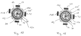
- Fig. 15 shows a first switching position, in which the opening 112 opposite the input 30, so that a flow connection from the suction port 34 to the suction port 38 of the impeller 14 is made. In the switching position according to Fig.
- the opening 112 is located above the inlet 130 so that a flow connection is created from the connection 128 to the suction opening 36 and via this into the suction mouth 38 of the impeller 14.
- the opening 112 is above the entrance 30, so in turn, a flow connection from the suction port 34th given to the suction mouth 38 of the impeller 14.
- a partial overlap of the opening 124 and the through hole 122 with the input 28 takes place, so that a connection between the pressure chamber 26 and the suction port 32 is made, which acts as a pressure port.
- the bypass opening 126 concurrently covers the input 130 and a portion of the input 28, so that also a connection from the terminal 128 via the input 130, the bypass opening 126 and the input 28 to the terminal 32 is provided.
- Fig. 18 shows a fourth switching position in which the passageway 122 completely covers the input 28, so that the terminal 32 is connected via the passage 122 and the opening 124 with the pressure chamber 26. At the same time, the bridging opening 126 only covers the entrance 130. The opening 112 also covers the entrance 30.
- the heating system in turn has a primary heat exchanger or a heat source 114, which may be, for example, a gas boiler.
- a first heating circuit 120 On the output side of the flow path is in a first heating circuit 120, which may be formed for example by conventional radiators or radiators.
- a flow path branches off to a secondary heat exchanger 56 for heating service water.
- the heating system further includes a floor heating circuit 116. The returns of the heating circuit 120 and the floor heating circuit 116 open into the suction port 34 on the pump housing 12. The return from the secondary heat exchanger 56 opens into the port 128, which, as will be described below, offers two functionalities.
- the connection 32 of the pump housing 12 is connected to the flow of the floor heating circuit 116.
- the impeller 14 promotes liquid from the suction port 34 via the pressure port 27 through the heat source 140 and the heating circuit 120 and back to the suction port 34.
- the valve element 18i in the second switching position which in Fig. 16 is shown, the plant is switched to domestic water operation, in this state, the pump assembly or the impeller 14 promotes liquid from the port 128, which serves as a suction port, through the pressure port 27, via the heat source 114 through the secondary heat exchanger 56 and back to the terminal 128.
- the valve element 18i in the third switching position which in Fig. 17 is shown, the underfloor heating circuit 116 is additionally supplied.
- the water flows into the suction mouth 38 of the impeller 14 and is conveyed via the pressure connection 27 via the heat source 114 in the manner described by the first heating circuit 120.
- the liquid emerges on the output side of the impeller 14 from the pressure chamber 26 into the opening 124 and through the through-passage 122 and thus flows to the connection 32 and via this into the underfloor heating circuit 116.
- FIG. 17 The switch position shown flows simultaneously via the bridging opening 126 liquid via the terminal 128 and the input 130 into the terminal 32. That is, here water flows through the heat source 114 through the secondary heat exchanger 26 and the terminal 128 to the terminal 32. Since in this heating operation on Secondary heat exchanger 56 is removed substantially no heat, so the port 32 hot water in addition to the cold water, which flows from the pressure chamber 26 via the passage 122 to the port 32, admixed. By changing the Opening degree over the valve position 18i, the amount of mixed warm water at port 32 can be varied.
- Fig. 18 shows a switching position in which the admixture is turned off and the terminal 32 is exclusively in communication with the pressure chamber 26 directly.
- the rotor 6 is preferably initially positioned when the second change of mode is performed again in such a way that the control device 17 rotates the rotor 6 by appropriate control of the stator 4 is not quite up to the stored angular position rotates, sondem preferably shortly before stops. Ie.
- the rotor 6 is rotated into a previously stored angular position or into an angular position which is slightly ahead of the last stored angular position in the direction of rotation.
- the rotor can be rotated together with the valve element 18, 18i in a desired second angular position, wherein the control device 17 controls the stator 6 so that the rotor 6 rotates in this second mode exactly to the desired angle.
- the counter-coupling 110 is taken over the clutch 108, so that the valve element 18, 18i is then rotated to the desired angular position.
- the rotor 6 is stopped and the control device 17 switches back to the first mode or the first operating mode and starts the rotor 6 in the opposite direction of rotation, so that the clutch 108 can disengage from the counter-coupling 110 and the rest by the axial Displacement of the valve element 18, 18i by the pressure generated in the pressure chamber 26, the clutch 108 and the counter-coupling 110 completely disengage and the valve element 18, 18i is held by engagement with the bottom of the pump housing 12 in the achieved switching position.
- the coupling 108 has two bevels 132 which extend from two end edges 134 which extend substantially diametrically with respect to the axis of rotation X.
- engagement surfaces 136 which essentially run in a plane which is spanned by the rotation axis X and a diameter line to this rotation axis X extend.
- the counter-coupling 110 has a web-shaped projection 138 extending in the diameter direction with respect to the axis of rotation X, which protrudes in the axial direction and has two substantially mutually parallel side surfaces, which in turn extend in planes which in the Essentially spanned by the diameter line and the axis of rotation X or parallel to these axes.
- a fixed axis extends in the direction of the axis of rotation X in the interior of the pump housing 12.
- the valve element 18, 18i is rotatably mounted.
- the axis 20 engages in a blind hole 140 in the bottom of the valve element 18, 18i, which faces away from the impeller 14, a.
- a seal 142 is arranged, which is on the outer circumference of the axis 20 slidably in abutment. The seal 142 seals the interior of the blind hole 140 to the outside.
- a lubricant can be arranged to lubricate the slide bearing permanently or pre-lubricate.
- the seal 142 allows a slight leakage, so that long-term liquid from the pump housing 12, in particular water, can penetrate into the interior of the blind hole 140 and there the lubrication between the valve element 18, 18i and axis 20 is used.
- the seal 142 is designed so that particles and impurities are retained so that a permanent ease of storage is ensured.
- the axis 20 also has a the impeller 14 facing circumferential shoulder 144, at which the axis 20 tapers. Between this shoulder 144 and the bottom of the blind hole 140, which is located on the impeller 14 facing the end, the spring 48 is supported, whose function has already been described above. In this way, the spring 48 is completely located in the interior of the blind hole 140, which defines the storage space, so that the spring 48 is protected from contamination from the pumped by the pump unit fluid.
- valve element 18, 18i could also be used together with the valve element 18, 18i, if this would be hydraulically coupled instead of the described mechanical coupling 108, 110. If the said coupling 108, 110 is omitted, the valve element could instead be rotated by the flow rotated by the impeller 14 in the pressure space 26 by acting on the cover 78, 78i. In addition, in such an embodiment could be stops which define the switching positions of the valve element 18, 18i. The movement between these switching positions could then be achieved by reversing the direction of rotation of the impeller 14.
- the pump housing 12 which also serves as a valve housing, integrally formed.
- the pump housing 12 could also be composed of several individual parts or could be designed in several parts.
- a pump housing separate from the valve housing could be provided, wherein the valve housing accommodates the valve element 18, 18i, while the pressure chamber 26 is formed in the pump housing.
Landscapes
- Engineering & Computer Science (AREA)
- Mechanical Engineering (AREA)
- General Engineering & Computer Science (AREA)
- Physics & Mathematics (AREA)
- Fluid Mechanics (AREA)
- Structures Of Non-Positive Displacement Pumps (AREA)
Abstract
Description
- Die Erfindung betrifft ein Kreiselpumpenaggregat mit einem elektrischen Antriebsmotor, einem von diesem angetriebenen Laufrad sowie ein in das Kreiselpumpenaggregat integriertes drehbares Ventilelement.
- Es sind Kreiselpumpenaggregate bekannt, welche im Pumpengehäuse ein bewegliches, insbesondere schwenkbares Ventilelement aufweisen, um die von dem Kreiselpumpenaggregat geförderte Flüssigkeitsströmung wahlweise, insbesondere abhängig von der Drehrichtung des Antriebsmotors in zwei verschiedene druckseitige Strömungswege zu lenken. Es sind auch Anordnungen bekannt, bei denen eine Umschalteinrichtung zwischen zwei saugseitigen Strömungswegen in das Kreiselpumpenaggregat integriert ist. Eine solche Anordnung ist beispielsweise aus
DE 90 139 92 U1 bekannt. Diese bekannte Umschalteinrichtung weist ein auf der Druckseite des Laufrades gelegenes Anströmelement auf, welches je nach Drehrichtung die Ventileinrichtung an der Saugseite umschaltet. Dies erfordert eine relativ aufwändige Mechanik. - Im Hinblick auf diesen Stand der Technik ist es Aufgabe der Erfindung, ein Kreiselpumpenaggregat mit einem integrierten Ventilelement dahingehend zu verbessern, dass ein einfacherer Aufbau des Kreiselpumpenaggregates bei gleichzeitig erhöhter Zuverlässigkeit der Schaltfunktion des Ventilelementes erreicht wird.
- Diese Aufgabe wird durch ein Kreiselpumpenaggregat mit den in Anspruch 1 angegebenen Merkmalen gelöst. Bevorzugte Ausführungsformen ergeben sich aus den Unteransprüchen, der nachfolgenden Beschreibung sowie den beigefügten Figuren.
- Das erfindungsgemäße Kreiselpumpenaggregat weist einen elektrischen Antriebsmotor auf, durch den zumindest ein Laufrad drehend antreibbar ist. Dazu ist das Laufrad mit dem Magnetrotor des Antriebsmotors drehfest verbunden, entweder direkt oder z. B. über eine Welle. Der Antriebsmotor ist vorzugsweise als nasslaufender elektrischer Antriebsmotor ausgebildet, d. h. er weist vorzugsweise ein Spaltrohr bzw. einen Spalttopf zwischen Stator und Rotor auf, sodass der Rotor in der von dem Laufrad zu fördernden Flüssigkeit rotiert. Das Laufrad ist in einem Pumpengehäuse angeordnet, welches die Strömungswege zu dem Laufrad hin und von dem Laufrad weg definiert. In dem Pumpengehäuse ist ferner ein Ventilelement angeordnet, welches zwischen zumindest zwei Schaltstellungen drehbar ist. Dies kann beispielsweise ein Ventilelement eines Umschaltventils oder Mischventils sein, wie es unten beschrieben wird.
- Erfindungsgemäß ist das Ventilelement im Innenraum des Pumpengehäuses an einem Lager drehbar gehalten. Durch die Lagerung des Ventilelementes im Inneren des Pumpengehäuses werden Wellendichtungen im Pumpengehäuse vermieden, welche erforderlich wären, falls die Lagerung außerhalb des Pumpengehäuses angeordnet wäre. Erfindungsgemäß ist das Lager in einem Lagerungsraum angeordnet, welcher von dem übrigen Innenraum des Pumpengehäuses, welcher ein zu förderndes Fluid bzw. eine zu fördernde Flüssigkeit aufnimmt, durch zumindest eine Dichtung getrennt ist. Vorzugsweise ist das Pumpenaggregat für Wasser als zu förderndes Fluid ausgelegt. So eignet das Kreiselpumpenaggregat z. B. zur Verwendung als Umwälzpumpe in einer Heizungs- und/oder Klimaanlage. Die Dichtung des Lagerungsraumes gegenüber dem Innenraum des Pumpengehäuses hat den Vorteil, dass Verunreinigungen in dem zu fördernden Fluid von der Lagerung im Wesentlichen ferngehalten werden. Gleichzeitig ist jedoch keine absolut hermetische Dichtung erforderlich, welche erforderlich wäre, falls die Lagerung außerhalb des Pumpengehäuses angeordnet wäre. Eine gewisse Leckage im Lager kann toleriert werden. Dennoch kann Flüssigkeit nicht nach außen aus dem Pumpengehäuse austreten. Dadurch, dass Verunreinigungen von dem Lager ferngehalten werden, kann eine leichtgängige Lagerung des Ventilelementes sichergestellt werden. Die leichtgängige Lagerung ist vorteilhaft, wenn das Ventilelement von dem Antriebsmotor ohne einen zusätzlichen Antrieb bewegt werden soll, insbesondere durch hydraulische Kopplung über das zu fördernde Fluid.
- Vorzugsweise kann der Lagerungsraum einstückig mit dem Ventilelement ausgebildet sein. D. h. zumindest ein Abschnitt einer Wandung, welche den Lagerungsraum begrenzt, ist einstückig mit zumindest einer Wandung des Ventilelementes ausgebildet. Besonders bevorzugt ist der Lagerungsraum durch eine Einbuchtung an einer Wandung des Ventilelementes, insbesondere einer Stirnseite des Ventilelementes ausgebildet. Dabei hat der Lagerungsraum vorzugsweise eine rohrförmige oder sacklochförmige Gestalt.
- Gemäß einer bevorzugten Ausführungsform der Erfindung kann das zumindest eine Lager im Inneren des Lagerungsraums durch ein Schmiermittel, vorzugsweise werkseitig, geschmiert sein. Bei dem Schmiermittel kann es sich beispielsweise um ein Fett oder ein anderes geeignetes Schmiermittel handeln. Das Schmiermittel ist bevorzugt werkseitig eingebracht, d. h. das Schmiermittel ist bei Auslieferung des Kreiselpumpenaggregates bereits im Lagerungsraum angeordnet. Wenn die Dichtung des Lagerungsraumes nicht absolut dicht ist, sondern eine gewisse Menge der zu fördernden Flüssigkeit durchlässt, ist es möglich, dass im Laufe der Zeit das Schmiermittel beim Betrieb des Kreiselpumpenaggregates durch die zu fördernde Flüssigkeit bzw. das zu fördernde Fluid verdünnt und ersetzt wird. Dann kann im Laufe der Zeit die zu fördernde Flüssigkeit die Funktion des Schmiermittels übernehmen. Das heißt, das Lager ist vorzugsweise so ausgebildet, dass das zu fördernde Fluid bzw. die zu fördernde Flüssigkeit als Schmiermittel dienen kann.
- Besonders bevorzugt ist das Lager als Gleitlager ausgebildet. Dies ermöglicht einen sehr einfachen Lageraufbau. Ferner kann ein solches Lager auch durch die zu fördernde Flüssigkeit geschmiert werden.
- Wie ausgeführt kann gemäß einer bevorzugten Ausführungsform die Dichtung für dasjenige Fluid bzw. die Flüssigkeit, zu deren Förderung das Kreiselpumpenaggregat ausgebildet ist, nicht vollständig dicht sein. Bevorzugt ist das zu fördernde Fluid Wasser, sodass die Dichtung entsprechend so abgestimmt ist, dass sie eine gewisse Flüssigkeitsmenge bzw. Wasser durchlässt. Dies hat den Vorteil, dass die Dichtung einfacher ausgebildet werden kann und darüber hinaus die Reibung im Bereich der Dichtung reduziert werden kann. Darüber hinaus kann vorteilhaft eine dauerhafte Schmierung des Lagers sichergestellt werden, wenn die eindringende Flüssigkeit, insbesondere das eindringende Wasser im Laufe der Zeit die Funktion eines Schmiermittels übernimmt. Vorteilhaft ist die Dichtung jedoch derart ausgebildet, dass sie in dem von dem Laufrad zu fördernden Fluid befindliche Partikel zurückhält. So werden Verunreinigungen von dem Lager ferngehalten, sodass langfristig die Leichtgängigkeit des zumindest einen Lagers in dem Lagerungsraum sichergestellt ist.
- Der Lagerungsraum kann so ausgestaltet sein, dass er nur an einer Seite zu dem Innenraum des Pumpengehäuses hin geöffnet ist, sodass nur an einer Seite des Lagers eine Dichtung angeordnet ist. Es ist jedoch auch denkbar, dass der Lagerungsraum so ausgebildet ist, dass an zwei Seiten des Lagers jeweils eine Dichtung angeordnet ist, welche den Lagerungsraum in der beschriebenen Weise gegenüber dem übrigen Innenraum des Pumpengehäuses abdichtet.
- Besonders bevorzugt ist das zumindest eine Lager zentral an dem Ventilelement angeordnet. Das heißt das Lager umgibt zentral die Drehachse des Ventilelementes. Dies hat den Vorteil, dass das Lager im Durchmesser sehr klein ausgebildet werden kann, sodass die Reibung im Lager reduziert wird. Darüber hinaus kragt das Ventilelement vorzugsweise in radialer Richtung über das Lager aus, sodass in diesem Bereich günstige Hebelverhältnisse zur Drehung des Ventilelementes um das zumindest eine Lager bestehen. Der Durchmesser des Lagers ist vorzugsweise kleiner als ein Viertel des Durchmessers des Ventilelementes.
- Weiter bevorzugt liegt das zumindest eine Lager in einem an der Saugseite des Laufrades gelegenen Bereich des Pumpengehäuses. Das heißt das zumindest eine Lager liegt in dem Bereich des Pumpengehäuses, durch welche die von dem Laufrad angesaugte Flüssigkeit strömt. Dies hat den Vorteil, dass die Lagerung des Ventilelementes nicht mit dem Laufrad und dem Antriebsmotor kollidiert.
- Gemäß einer besonders bevorzugten Ausführungsform ist das zumindest eine Ventilelement zu seiner Bewegung zwischen den Schaltstellungen mit dem Antriebsmotor mechanisch, magnetisch und/oder hydraulisch gekoppelt. Hierzu kann eine Kupplung zwischen dem Antriebsmotor und dem Ventilelement vorgesehen sein, beispielsweise zwischen einer Rotorwelle oder dem Laufrad auf der einen Seite und dem Ventilelement auf der anderen Seite. Die Kupplung kann dabei kraft- und/oder reibschlüssig ausgebildet sein. Weiter bevorzugt kann die Kupplung lösbar sein, sodass sie gezielt außer Eingriff gebracht werden kann. Dies kann beispielsweise in Abhängigkeit der Drehzahl des Antriebsmotors und/oder des Druckes im druckseitigen Bereich des Pumpengehäuses geschehen. So kann durch den Antriebsmotor auch das Ventilelement zwischen den Schaltstellungen gezielt bewegt werden, ohne dass ein separater Antrieb für das Ventilelement erforderlich wäre. Wenn der Antriebsmotor mit dem Ventilelement hydraulisch gekoppelt ist, erfolgt diese hydraulische Kopplung vorzugsweise über das von dem Laufrad in Bewegung versetzte Fluid. Insbesondere kann das Fluid bzw. die Flüssigkeit in dem Pumpengehäuse von dem Laufrad in eine Drehbewegung versetzt werden, welche durch Reibung auf das Ventilelement übertragen wird, sodass das Ventilelement von der Strömung mitgedreht wird und so zwischen den Schaltstellungen bewegt werden kann. Um eine wechselseitige Bewegung zwischen zwei Schaltstellungen zu ermöglichen, können der Antriebsmotor und damit das Laufrad vorzugsweise in zwei entgegengesetzten Drehrichtungen antreibbar sein, sodass auch die rotierende Strömung im Pumpengehäuse wahlweise in unterschiedlichen Drehrichtungen verläuft. Die hydraulische Kopplung hat den Vorteil, dass sie leicht durch Schlupf außer Eingriff treten kann. Das heißt, wenn das Ventilelement eine vorgegebene Schaltstellung erreicht und in dieser fixiert ist, kann die Strömung in dem Pumpengehäuse weiterverlaufen ohne das Ventilelement weiter zu bewegen. Dabei verursacht die Strömung dann eine Reibung an der Oberfläche des Ventilelementes, welche jedoch im Wesentlichen der üblichen hydraulischen Reibung an der Innenseite des Pumpengehäuses entspricht. Insbesondere für die hydraulische als auch für die mechanische Kupplung ist es ferner vorteilhaft, wenn die Drehachse des Ventilelementes fluchtens zu der Drehachse des Antriebsmotors liegt.
- Gemäß einer weiteren bevorzugten Ausführungsform kann zumindest ein Krafterzeugungsmittel vorhanden sein, welches auf das zumindest eine Ventilelement eine Kraft in Richtung einer der zumindest zwei Schaltstellungen ausübt, wobei die Kraft vorzugsweise eine Federkraft, eine magnetische Kraft und/oder die Schwerkraft ist. Bei einer solchen Ausgestaltung kann das Ventilelement durch das Krafterzeugungsmittel beim Abschalten des Antriebsmotors selbsttätig in eine Ausgangslage, welche bevorzugt einer der Schaltstellungen entspricht, zurückbewegt werden. Das heißt bei dieser Ausführungsform ist keine Drehrichtungsumkehr des Antriebsmotors erforderlich, um das Ventilelement zurück in seine Ausgangslage zu bewegen. Aus der Ausgangslage in die andere Schaltstellung kann das Ventilelement aufgrund einer Kopplung mit dem Antriebsmotor durch dessen Drehung bewegt werden. Insbesondere um das Ventilelement in der Ausgangslage im Betrieb des Antriebsmotors zu halten, kann eine zweite Kupplung vorgesehen sein, welche das Ventilelement in dieser Lage insbesondere reibschlüssig fixiert. Diese Kupplung kann beispielsweise durch den Druck im Innenraum des Pumpengehäuses, welcher von dem Laufrad verursacht wird, in eine gekuppelte und damit haltende Position gedrückt werden. Ob das Ventilelement aus der Ausgangslage bewegt wird oder nicht kann bei einer solchen Ausgestaltung durch entsprechende Ansteuerung des Antriebsmotors erreicht werden. Der Antriebsmotor ist vorzugsweise mit einer Steuereinrichtung versehen, welche es ermöglicht die Drehzahl und/oder Beschleunigung des Antriebsmotors zu regulieren. Wenn beispielsweise der Antriebsmotor sehr schnell beschleunigt wird, kann dies dazu führen, dass sich im Pumpenraum sehr schnell ein Druck aufbaut, welcher dazu genutzt werden kann, eine Kupplung, welche das Ventilelement fixiert schnell in Eingriff zu bringen, bevor das Ventilelement durch eine Strömung in die andere Schaltstellung bewegt wird. So kann das Ventilelement in seiner Ausgangslage gehalten werden. Wenn hingegen der Antriebsmotor langsam beschleunigt wird, kann sich eine rotierende Strömung im Pumpengehäuse ausbilden, bevor der Druck so hoch ist, dass das Ventilelement fixiert wird. So kann das Ventilelement dann durch die Strömung in die andere Schaltstellung bewegt werden.
- Das zumindest eine Lager lässt vorzugsweise eine axiale Bewegung des Ventilelementes zwischen einer ersten und einer zweiten Position zu. Diese Ausgestaltung ermöglicht es, das Ventilelement axial zu bewegen, um es z. B. in der zweiten Position in eine dichtende und haltende Anlage mit dem Pumpengehäuse oder einer mit dem Pumpengehäuse verbundenen Anlagefläche zu bringen. In dieser Position kann das Ventilelement dann beispielsweise dichtend an zumindest einem Ventilsitz anliegen. Gleichzeitig kann die Anlage die Funktion der oben beschriebenen zweiten Kupplung zur Fixierung des Ventilelementes übernehmen. In der ersten Position hingegen ist das Ventilelement vorzugsweise von den Anlageflächen beabstandet, sodass es sich vorzugsweise frei um das zumindest eine Lager drehen kann.
- Die erste Position und/oder die zweite Position sind vorzugsweise durch einen Anschlag begrenzt, wobei vorzugsweise zumindest einer der Anschläge innerhalb des Lagerungsraumes gelegen ist. In der zweiten Position kann der Anschlag beispielsweise durch eine Anlagefläche gebildet sein, in welcher das Ventilelement zur Anlage kommt. Ein zweiter Anschlag ist vorzugsweise in entgegengesetzter Richtung vorhanden, damit das Ventilelement sich nicht weiter als ein vorbestimmtes Maß von der Anlagefläche oder dem Pumpengehäuse wegbewegen kann.
- Weiter bevorzugt ist zumindest ein Rückstellelement, insbesondere eine Rückstellfeder vorgesehen, welches auf das Ventilelement eine Rückstellkraft in axialer Richtung ausübt. Vorzugsweise ist das Rückstellelement so angeordnet, dass es das Ventilelement in eine Position bewegt, in welcher es von einer Anlager- und/oder Dichtfläche beabstandet ist und frei um das zumindest eine Lager drehbar ist. Gegen das Rückstellelement wird das Ventilelement vorzugsweise durch eine im Pumpengehäuse erzeugte Druckkraft gedrückt. Dazu weist das Ventilelement vorzugsweise eine Druckfläche auf, welche einem Druckraum im Inneren des Pumpengehäuses zugewandt ist und auf welcher der Flüssigkeitsdruck, welcher von dem Laufrad im Inneren des Pumpengehäuses erzeugt wird, wirkt. Wenn die von dem Rückstellelement erzeugte Kraft von dieser Druckkraft überschritten wird, bewegt sich das Ventilelement gegen das Rückstellelement in eine haltende und/oder dichtende Position, wie sie oben beschrieben wurde.
- Vorzugsweise ist das Rückstellelement innerhalb des Lagerungsraumes angeordnet. So ist es vor Verunreinigungen durch die zumindest eine Dichtung geschützt. Gemäß einer weiteren besonders bevorzugten Ausführungsform der Erfindung ist das Ventilelement derart in dem Pumpengehäuse angeordnet, dass es einen mit einer Saugseite des Laufrades verbundenen Saugraum von einem mit der Druckseite des Laufrades verbundenen Druckraum trennt. Bei dieser Anordnung kann der Differenzdruck zwischen Saugraum und Druckraum dazu genutzt werden, das Ventilelement gegen eine Dicht- bzw. Anlagefläche zu drücken, um zum einen die Saugseite gegen die Druckseite abzudichten und zum anderen auch um Ventilöffnungen in gewünschter Weise abzudichten. Gleichzeitig kann eine Kupplung geschaffen werden, welche das Ventilelement bei Anlage an der Anlagefläche in einer gewünschten Schaltstellung fixiert. Dem Druckraum zugewandt weist das Ventilelement dazu in der beschriebenen Weise vorzugsweise eine Druckfläche auf, auf welche der ausgangsseitige Druck des Laufrades wirkt.
- Weiter bevorzugt weist das Kreiselpumpenaggregat zwei alternative Strömungswege auf, wobei das zumindest eine Ventilelement in diesen Strömungswegen derart angeordnet ist, dass in den zumindest zwei Schaltstellungen die Strömungswege unterschiedlich geöffnet sind. Das Ventilelement kann als reines Umschaltventil so ausgebildet sein, dass es in einer ersten Schaltstellung einen ersten Strömungsweg öffnet und einen zweiten Strömungsweg verschießt und umgekehrt in einer zweiten Schaltstellung den ersten Strömungsweg verschließt und den zweiten Strömungsweg öffnet. Unter einem Ventilelement im Sinne dieser Erfindung ist auch eine gekoppelte Anordnung zweier Ventilelemente, welche gekoppelt miteinander bewegt werden, zu verstehen. Alternativ oder zusätzlich kann das Ventilelement eine Mischfunktion bereitstellen, indem es beispielsweise auch Zwischenpositionen zwischen den beschriebenen zwei Schaltstellungen einnehmen kann, in welchen beide Strömungswege um ein gewisses Maß geöffnet sind. Durch Verlagerung des Ventilelementes in diesen Zwischenstellungen können die Strömungswege unterschiedlich weit geöffnet werden, sodass ein Mischungsverhältnis der Strömungen durch die beiden Strömungswege geändert werden kann. Vorzugsweise ist das Ventilelement so ausgebildet und angeordnet, dass es bei seiner Bewegung einen der Strömungswege um dasselbe Maß öffnet, um welches gleichzeitig der andere Strömungsweg geschlossen wird.
- Die beiden Strömungswege sind besonders bevorzugt saugseitig des Laufrades gelegen. Das heißt das Laufrad saugt je nach Stellung des Ventilelementes aus einem der beiden Strömungswege oder auch aus beiden Strömungswegen an, wobei dann durch Verlagerung des Ventilelementes die Mischung der Strömungen aus den beiden Strömungswegen verändert werden kann. Alternativ kann das Ventilelement auch an der Druckseite des Laufrades gelegen sein bzw. bewirken, sodass es die Strömung zwischen zwei druckseitigen Strömungswegen umschaltet oder bei Ausgestaltung als Mischventil mischt.
- Nachfolgend wird die Erfindung beispielhaft anhand der beigefügten Figuren beschrieben. In diesen zeigt:
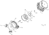
- Fig. 1
- eine Explosionsansicht des Kreiselpumpenaggregates gemäß einer neunten Ausführungsform der Erfindung,
- Fig. 2
- eine perspektivische Ansicht des Kreiselpumpenaggregates gemäß
Fig. 1 mit abgenommenem Pumpengehäuse und Ventilelement, - Fig. 3
- eine perspektivische Ansicht der Motorwelle des Kreiselpumpenaggregates gemäß
Fig. 1 und2 sowie des Kupplungsteils des Ventilelementes, - Fig. 4
- eine Schnittansicht des Kreiselpumpenaggregates gemäß
Fig. 1 mit dem Ventilelement in einer ersten Position, - Fig. 5
- eine Schnittansicht gemäß
Fig. 4 mit dem Ventilelement in einer zweiten Position, - Fig. 6
- eine Draufsicht auf das geöffnete Pumpengehäuse des Kreiselpumpenaggregates gemäß
Fig. 1 bis 3 mit dem Ventilelement in einer ersten Schaltstellung, - Fig. 7
- eine Ansicht gemäß
Fig. 6 mit dem Ventilelement in einer zweiten Schaltstellung, - Fig. 8
- eine Ansicht gemäß
Fig. 6 und 7 mit dem Ventilelement in einer dritten Schaltstellung, - Fig. 9
- schematisch den hydraulischen Aufbau einer Heizungsanlage mit einem Kreiselpumpenaggregat gemäß
Fig. 1 bis 8 , - Fig. 10
- eine Explosionsansicht eines Kreiselpumpenaggregates gemäß einer zweiten Ausführungsform der Erfindung,
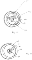
- Fig. 11
- eine perspektivische Ansicht des geöffneten Ventilelementes des Kreiselpumpenaggregates gemäß
Fig. 10 , - Fig. 12
- eine perspektivische Ansicht des geschlossenen Ventilelementes gemäß
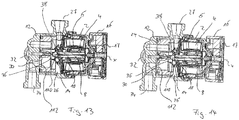
Fig. 11 , - Fig. 13
- eine Schnittansicht des Kreiselpumpenaggregates gemäß
Fig. 10 mit dem Ventilelement in einer ersten Position, - Fig. 14
- eine Schnittansicht gemäß
Fig. 13 mit dem Ventilelement in einer zweiten Position, - Fig. 15
- eine Draufsicht auf das geöffnete Pumpengehäuse des Kreiselpumpenaggregates gemäß
Fig. 10 bis 14 mit dem Ventilelement in einer ersten Schaltstellung, - Fig. 16
- eine Ansicht gemäß
Fig. 15 mit dem Ventilelement in einer zweiten Schaltstellung, - Fig. 17
- eine Ansicht gemäß
Fig. 15 und 16 mit dem Ventilelement in einer dritten Schaltstellung, - Fig. 18
- eine Ansicht gemäß
Fig. 15 bis 17 mit dem Ventilelement in einer vierten Schaltstellung und - Fig. 19
- schematisch den hydraulischen Aufbau einer Heizungsanlage mit einem Kreiselpumpenaggregat gemäß
Fig. 10 bis 18 , - Fig. 20
- vergrößert eine Darstellung der Lagerung des Ventilelementes 18, 18i in den Ausführungsbeispielen gemäß
Fig. 1 bis 19 . - Die in der nachfolgenden Beschreibung beschriebenen Ausführungsbeispiele des erfindungsgemäßen Kreiselpumpenaggregates betreffen Anwendungen in Heizungs- und/oder Klimasystemen, in welchen von dem Kreiselpumpenaggregat ein flüssiger Wärmeträger, insbesondere Wasser, umgewälzt wird.
- Das Kreiselpumpenaggregat gemäß beider Ausführungsformen der Erfindung weist ein Motorgehäuse 2 auf, in welchem ein elektrischer Antriebsmotor angeordnet ist. Dieser weist in bekannter Weise einen Stator 4 sowie einen Rotor 6 auf, welcher auf einer Rotorwelle 8 angeordnet ist. Der Rotor 6 dreht in einem Rotorraum, welcher von dem Statorraum, in welchem der Stator 4 angeordnet ist, durch ein Spaltrohr bzw. einen Spalttopf 10 getrennt ist. Das heißt, es handelt sich hierbei um einen nasslaufenden elektrischen Antriebsmotor. An einem Axialende ist das Motorgehäuse 2 mit einem Pumpengehäuse 12 verbunden, in welchem ein mit der Rotorwelle 8 drehfest verbundenes Laufrad 14 rotiert.
- An dem dem Pumpengehäuse 12 entgegengesetzten Axialende des Motorgehäuses 2 ist ein Elektronikgehäuse 16 angeordnet, welches eine Steuerelektronik bzw. Steuereinrichtung 17 zur Ansteuerung des elektrischen Antriebsmotors in dem Pumpengehäuse 2 beinhaltet. Das Elektronikgehäuse 16 könnte in entsprechender Weise auch an einer anderen Seite des Statorgehäuses 2 angeordnet sein.
- In dem Pumpengehäuse 12 ist darüber hinaus ein bewegliches Ventilelement 18 angeordnet. Dieses Ventilelement 18 ist auf einer Achse 20 im Inneren des Pumpengehäuses 12 drehbar gelagert, und zwar so, dass die Drehachse des Ventilelementes 18 mit der Drehachse X des Laufrades 14 fluchtet. Die Achse 20 ist am Boden des Pumpengehäuses 12 drehfest fixiert. Das Ventilelement 18 ist nicht nur um die Achse 20 drehbar, sondern um ein gewisses Maß in Längsrichtung X bewegbar. In einer Richtung wird diese lineare Bewegbarkeit durch das Pumpengehäuse 12, an welches das Ventilelement 18 mit seinem Außenumfang anschlägt, begrenzt.
- Das Ventilelement 18 trennt in dem Pumpengehäuse 12 einen Saugraum 24 von einem Druckraum 26. In dem Druckraum 26 rotiert das Laufrad 14. Der Druckraum 26 ist mit dem Druckanschluss bzw. Druckstutzen 27 des Kreiselpumpenaggregates verbunden, welcher den Auslass des Kreiselpumpenaggregates bildet.
- Bei beiden gezeigten Ausführungsformen ist eine mechanische Kupplung zwischen dem Antriebsmotor und dem Ventilelement vorgesehen, wobei bei diesen Ausführungsformen der Antriebsmotor von der Steuereinrichtung 17 in zwei verschiedenen Betriebsarten bzw. Betriebsmodi ansteuerbar ist. In einer ersten Betriebsart, welche dem Normalbetrieb des Umwälzpumpenaggregates entspricht, rotiert der Antriebsmotor in herkömmlicher Weise mit einer gewünschten, insbesondere von der Steuereinrichtung 17 einstellbaren, Drehzahl. In der zweiten Betriebsart wird der Antriebsmotor im Open-Loop-Betrieb angesteuert, sodass der Rotor schrittweise in einzelnen von der Steuereinrichtung 17 vorgegebenen Winkelschritten, welche kleiner als 360° sind, gedreht werden kann. So kann der Antriebsmotor nach Art eines Schrittmotors in einzelnen Schritten bewegt werden, was bei diesen Ausführungsbeispielen dazu genutzt wird, das Ventilelement gezielt in kleinen Winkelschritten in eine definierte Position zu bewegen, wie es nachfolgend beschrieben wird.
- Bei der ersten Ausführungsform gemäß
Fig. 29 bis 37 ist in dem Pumpengehäuse 2 ein Mischventil integriert, wie es beispielsweise zur Temperatureinstellung für eine Fußbodenheizung genutzt werden kann. - Das Motorgehäuse 2 mit dem Elektronikgehäuse 16 entspricht der vorangehend beschriebenen Ausgestaltung. Das Pumpengehäuse 12 weist neben dem Druckanschluss 27 zwei saugseitige Anschlüsse 32 und 34 auf, welche am Boden des Pumpengehäuses 12 in Eingängen 28 und 30 münden, welche in einer Ebene quer zu der Drehachse X gelegen sind.
- Das Ventilelement 18 ist trommelförmig ausgebildet und besteht aus einem topfförmigen Unterteil 76, welches an seiner dem Laufrad 14 zugewandten Seite durch einen Deckel 78 verschlossen ist. Im Zentralbereich des Deckels 78 ist eine Saugöffnung 36 ausgebildet. Die Saugöffnung 36 ist mit dem Saugmund 38 des Laufrades 14 in Eingriff. Das Ventilelement 18 ist auf einer Achse 20, welche im Boden des Pumpengehäuses 12 angeordnet ist, drehbar gelagert. Dabei entspricht die Drehachse des Ventilelementes 18 der Drehachse X der Rotorwelle 8. Das Ventilelement 18 ist ebenfalls entlang der Achse X axial verschiebbar und wird durch eine Feder 48 in die in
Fig. 5 gezeigte Ruhelage gedrückt, in welcher sich das Ventilelement 18 in einer gelösten Position befindet, in welcher das Unterteil 76 nicht am Boden des Pumpengehäuses 12 anliegt, sodass das Ventilelement 18 im Wesentlichen frei um die Achse 20 drehbar ist. Als axialer Anschlag fungiert in der gelösten Position das Stirnende der Rotorwelle 8, welches als Kupplung 108 ausgebildet ist. Die Kupplung 108 tritt mit einer Gegenkupplung 110, welche drehfest an dem Ventilelement 18 angeordnet ist, in Eingriff. Die Kupplung 108 weist angeschrägte Kupplungsflächen auf, welche entlang einer Umfangslinie im Wesentlichen ein Sägezahnprofil in der Weise beschreiben, dass lediglich in einer Drehrichtung eine Drehmomentübertragung von der Kupplung 108 auf die Gegenkupplung 110 möglich ist, nämlich in der Drehrichtung A inFig. 3 . In der entgegengesetzten Drehrichtung B rutscht die Kupplung hingegen durch, wobei es zu einer Axialbewegung des Ventilelementes 18 kommt. Die Drehrichtung B ist diejenige Drehrichtung, in welcher das Pumpenaggregat im Normalbetrieb angetrieben wird. Die Drehrichtung A hingegen wird zur gezielten Verstellung des Ventilelementes 18 genutzt. Das heißt hier ist eine drehrichtungsabhängige Kupplung ausgebildet. Zusätzlich jedoch tritt die Gegenkupplung 110 von der Kupplung 108 durch den Druck im Druckraum 26 außer Eingriff. Steigt der Druck im Druckraum 26 an, wirkt auf den Deckel 78 eine Druckkraft, welche der Federkraft der Feder 48 entgegengesetzt ist und diese übersteigt, sodass das Ventilelement 18 in die anliegende Position gedrückt wird, welche inFig. 4 gezeigt ist. In dieser liegt das Unterteil 76 an der Bodenseite des Pumpengehäuses 12 an, sodass zum einen das Ventilelement 18 kraftschlüssig gehalten wird und zum anderen eine dichte Anlage erreicht wird, welche die Druck- und die Saugseite in der nachfolgend beschriebenen Weise gegeneinander abdichtet. - Der Sauganschluss 32 mündet an dem Eingang 28 und der Sauganschluss 34 mündet an dem Eingang 30 im Boden des Pumpengehäuses 12 in dessen Innenraum, das heißt, den Saugraum 24 hinein. Das Unterteil 76 des Ventilelementes 18 weist in seinem Boden eine bogenförmige Öffnung 112 auf, welche sich im Wesentlichen über 90° erstreckt.
Fig. 6 zeigt eine erste Schaltstellung, in welcher die Öffnung 112 lediglich den Eingang 30 überdeckt, sodass ein Strömungsweg nur von dem Sauganschluss 34 zu der Saugöffnung 36 und damit zum Saugmund 38 des Laufrades 14 gegeben ist. Der zweite Eingang 28 wird durch den in seinem Umfangsbereich anliegenden Boden des Ventilelementes 18 dicht verschlossen.Fig. 8 zeigt die zweite Schaltstellung, in welcher die Öffnung 112 lediglich den Eingang 28 überdeckt, während der Eingang 30 verschlossen ist. In dieser Schaltstellung ist lediglich ein Strömungsweg von dem Sauganschluss 32 zum Saugmund 38 hin geöffnet.Fig. 7 zeigt nun eine Zwischenstellung, in welcher die Öffnung 112 beide Eingänge 28 und 30 überdeckt, wobei der Eingang 30 nur teilweise freigegeben ist. Durch Änderung des Grades der Freigabe des Anschlusses 30 kann ein Mischungsverhältnis zwischen den Strömungen aus den Eingängen 28 und 30 geändert werden. Über die schrittweise Verstellung der Rotorwelle 8 kann auch das Ventilelement 18 in kleinen Schritten verstellt werden, um das Mischungsverhältnis zu ändern. - Eine solche Funktionalität kann beispielsweise in einem hydraulischen System, wie es in Fig. 37 gezeigt ist, zur Anwendung kommen. Dort ist das Kreiselpumpenaggregat mit dem integrierten Ventil, wie es vorangehend beschrieben wurde, durch die gestrichelte Linie 1 gekennzeichnet. Der hydraulische Kreis weist eine Wärmequelle 114 in Form beispielsweise eines Gasheizkessels auf, dessen Ausgang in beispielsweise den Sauganschluss 34 des Pumpengehäuses 12 mündet. An den Druckanschluss 27 des Kreiselpumpenaggregates 1 schließt sich in diesem Beispiel ein Fußbodenheizkreis 116 an, dessen Rücklauf sowohl mit dem Eingang der Wärmequelle 114 als auch mit dem Sauganschluss 32 des Kreiselpumpenaggregates verbunden ist. Über ein zweites Umwälzpumpenaggregat 118 kann ein weiterer Heizkreis 120 mit einem Wärmeträger versorgt werden, welcher die ausgangsseitige Temperatur der Wärmequelle 114 aufweist. Der Fußboden-Heizkreis 116 hingegen kann in seiner Vorlauftemperatur in der Weise geregelt werden, dass kaltes Wasser aus dem Rücklauf dem heißen Wasser ausgangsseitig der Wärmequelle 114 zugemischt wird, wobei durch Veränderung der Öffnungsverhältnisse der Eingänge 28 und 30 in der oben beschriebenen Weise das Mischungsverhältnis durch Drehung des Ventilelementes 18h verändert werden kann.
- Das zweite Ausführungsbeispiel gemäß
Fig. 10 bis 19 zeigt ein Kreiselpumpenaggregat, welches zusätzlich zu der vorangehend beschriebenen Mischerfunktionalität noch eine Umschaltfunktionalität zur zusätzlichen Versorgung eines Sekundärwärmetauschers zur Brauchwassererwärmung aufweist. - Die Lagerung und der Antrieb des Ventilelementes 18i erfolgt bei dieser Ausführungsform genauso wie bei der neunten Ausführungsform. Im Unterschied zu dem Ventilelement 18 weist das Ventilelement 18i zusätzlich zu der Öffnung 112 einen Durchgangskanal 122 auf, welcher sich von einer Öffnung 124 in den Deckel 78i zu einer Öffnung im Boden des Unterteils 76i erstreckt und somit die beiden Axialenden des Ventilelementes 18i miteinander verbindet. Ferner ist in dem Ventilelement 18i noch eine lediglich zur Unterseite, das heißt, zum Boden des Unterteils 76i und damit zum Saugraum 24 hin geöffnete bogenförmige Überbrückungsöffnung 126 ausgebildet, welche zum Druckraum 26 hin durch den Deckel 78i verschlossen ist.
- Das Pumpengehäuse 12 weist neben dem Druckanschluss 27 und den beiden zuvor beschriebenen Sauganschlüssen 34 und 32 einen weiteren Anschluss 128 auf. Der Anschluss 128 mündet in einem Eingang 130 im Boden des Umwälzpumpenaggregates 12 zusätzlich zu den Eingängen 28 und 30 in den Saugraum 24 hinein. Anhand der
Fig. 15 bis 18 werden die verschiedenen Schaltstellungen erläutert, wobei in diesen Figuren der Deckel 78i des Ventilelementes 18i teilweise geöffnet gezeigt ist, um die Stellung der darunter liegenden Öffnungen zu verdeutlichen.Fig. 15 zeigt eine erste Schaltstellung, in welcher die Öffnung 112 dem Eingang 30 gegenüberliegt, sodass eine Strömungsverbindung von dem Sauganschluss 34 zum Saugmund 38 des Laufrades 14 hergestellt wird. In der Schaltstellung gemäßFig. 16 liegt die Öffnung 112 über dem Eingang 130, sodass eine Strömungsverbindung von dem Anschluss 128 zu der Saugöffnung 36 und über diese in den Saugmund 38 des Laufrades 14 geschaffen wird. In einer weiteren Schaltstellung, welcheFig. 17 zeigt, liegt die Öffnung 112 über dem Eingang 30, sodass wiederum eine Strömungsverbindung von dem Sauganschluss 34 zum Saugmund 38 des Laufrades 14 gegeben ist. Gleichzeitig findet eine teilweise Überdeckung der Öffnung 124 und des Durchgangsloches 122 mit dem Eingang 28 statt, sodass eine Verbindung zwischen dem Druckraum 26 und dem Sauganschluss 32 hergestellt ist, welcher hier als Druckanschluss fungiert. Gleichzeitig überdeckt die Überbrückungsöffnung 126 gleichzeitig den Eingang 130 und einen Teil des Einganges 28, sodass ebenfalls eine Verbindung von dem Anschluss 128 über den Eingang 130, die Überbrückungsöffnung 126 und den Eingang 28 zu dem Anschluss 32 geschaffen wird. -
Fig. 18 zeigt eine vierte Schaltstellung, in welcher der Durchgangskanal 122 den Eingang 28 vollständig überdeckt, sodass der Anschluss 32 über den Durchgangskanal 122 und die Öffnung 124 mit dem Druckraum 26 verbunden ist. Gleichzeitig überdeckt die Überbrückungsöffnung 126 nur noch den Eingang 130. Die Öffnung 112 überdeckt weiterhin den Eingang 30. - Ein solches Kreiselpumpenaggregat kann beispielsweise in einem Heizungssystem, wie es in
Fig. 19 gezeigt ist, Verwendung finden. Dort begrenzt die gestrichelte Linie das Kreiselpumpenaggregat 1, wie es gerade anhand derFig. 10 bis 18 beschrieben wurde. Das Heizungssystem weist wiederum einen Primärwärmetauscher bzw. eine Wärmequelle 114 auf, welche beispielsweise ein Gasheizkessel sein kann. Ausgangsseitig verläuft der Strömungsweg in einen ersten Heizkreis 120, welcher beispielsweise von herkömmlichen Heizkörpern bzw. Radiatoren gebildet sein kann. Gleichzeitig zweigt ein Strömungsweg zu einem Sekundärwärmetauscher 56 zur Erwärmung von Brauchwasser ab. Das Heizungssystem weist ferner einen Fußbodenheizkreis 116 auf. Die Rückläufe des Heizkreises 120 und des Fußbodenheizkreises 116 münden in den Sauganschluss 34 am Pumpengehäuse 12. Der Rücklauf aus dem Sekundärwärmetauscher 56 mündet in den Anschluss 128, welcher, wie nachfolgend beschrieben wird, zwei Funktionalitäten bietet. Der Anschluss 32 des Pumpengehäuses 12 ist mit dem Vorlauf des Fußbodenheizkreises 116 verbunden. - Wenn sich das Ventilelement 18i in der ersten in
Fig. 15 gezeigten Schaltstellung befindet, fördert das Laufrad 14 Flüssigkeit aus dem Sauganschluss 34 über den Druckanschluss 27 durch die Wärmequelle 140 und dem Heizkreis 120 und zurück zu dem Sauganschluss 34. Befindet sich das Ventilelement 18i in der zweiten Schaltstellung, welche inFig. 16 gezeigt ist, ist die Anlage auf Brauchwasserbetrieb umgeschaltet, in diesem Zustand fördert das Pumpenaggregat bzw. das Laufrad 14 Flüssigkeit von dem Anschluss 128, welcher als Sauganschluss dient, durch den Druckanschluss 27, über die Wärmequelle 114 durch den Sekundärwärmetauscher 56 und zurück zu dem Anschluss 128. Befindet sich das Ventilelement 18i in der dritten Schaltstellung, welche inFig. 17 gezeigt ist, wird zusätzlich der Fußbodenheizkreis 116 versorgt. Über den Sauganschluss 34 strömt das Wasser in den Saugmund 38 des Laufrades 14 und wird über den Druckanschluss 27 über die Wärmequelle 114 in der beschriebenen Weise durch den ersten Heizkreis 120 gefördert. Gleichzeitig tritt die Flüssigkeit ausgangsseitig des Laufrades 14 aus dem Druckraum 26 in die Öffnung 124 und durch den Durchgangskanal 122 hindurch und fließt so zu dem Anschluss 32 und über diesen in den Fußbodenheizkreis 116. - In der in
Fig. 17 gezeigten Schaltstellung fließt gleichzeitig über die Überbrückungsöffnung 126 Flüssigkeit über den Anschluss 128 und den Eingang 130 in den Anschluss 32. Das heißt, hier strömt Wasser über die Wärmequelle 114 durch den Sekundärwärmetauscher 26 und den Anschluss 128 zu dem Anschluss 32. Da in diesem Heizbetrieb am Sekundärwärmetauscher 56 im Wesentlichen keine Wärme abgenommen wird, wird so dem Anschluss 32 heißes Wasser zusätzlich zu dem kalten Wasser, welches aus dem Druckraum 26 über den Durchgangskanal 122 zu dem Anschluss 32 strömt, zugemischt. Durch Veränderung des Öffnungsgrades über die Ventilstellung 18i kann die Menge des zugemischten warmen Wassers am Anschluss 32 variiert werden.Fig. 18 zeigt eine Schaltstellung, in welcher die Zumischung abgeschaltet ist und der Anschluss 32 ausschließlich mit dem Druckraum 26 direkt in Verbindung ist. In diesem Zustand wird das Wasser im Fußbodenkreis 116 ohne Wärmezufuhr im Kreis gefördert. Es ist zu erkennen, dass durch die Veränderung der Schaltstellungen des Ventilelementes 18i bei dieser Ausführungsform sowohl eine Umschaltung zwischen Heizung und Brauchwassererwärmung erreicht werden kann als auch gleichzeitig die Versorgung von zwei Heizkreisen mit unterschiedlichen Temperaturen, nämlich eines ersten Heizkreises 120 mit der Ausgangstemperatur der Wärmequelle 114 und eines Fußbodenheizkreises 116 mit einer über eine Mischfunktion reduzierte Temperatur. - Aufgrund der Tatsache, dass die Kupplung 108 und die Gegenkupplung 110 in der ersten Betriebsart im Normalbetrieb des Umwälzpumpenaggregates, wenn das Laufrad 14 Flüssigkeit fördert, außer Eingriff treten, stellt sich das Problem, beim Wechsel in die zweite Betriebsart, was eine Drehrichtungsumkehr erfordert, den Rotor 6 und das Ventilelement 18, 18i wieder in definierte Ausrichtung bezüglich ihrer Winkellagen zu bringen. Das Ventilelement 18, 18i sollte im Wesentlichen in der Position gehalten sein, in welcher es war, als das Pumpenaggregat durch die Steuereinrichtung 17 zum letzten Mal von der zweiten Betriebsart in die erste Betriebsart gewechselt ist. Gleichzeitig ist der Steuereinrichtung 17 die Position des Rotors 6 bekannt und die Steuereinrichtung 17 ist so ausgebildet, dass sie die Rotorposition speichert. Da jedoch nicht ganz ausgeschlossen werden kann, dass sich das Ventilelement 18, 18i möglicherweise um ein geringes Maß verlagert hat, wird beim erneuten Wechsel in die zweite Betriebsart bevorzugt zunächst eine Positionierung des Rotors 6 in der Weise vorgenommen, dass die Steuereinrichtung 17 den Rotor 6 durch entsprechende Ansteuerung des Stators 4 nicht ganz bis in die gespeicherte Winkellage dreht, sondem vorzugsweise kurz vorher anhält. D. h. in einem ersten Schritt wird bei der Inbetriebnahme des zweiten Betriebsmodus der Rotor 6 in eine zuvor gespeicherte Winkellage gedreht oder in eine Winkellage, welche in Drehrichtung geringfügig vor der zuletzt gespeicherten Winkellage liegt. Anschließend kann der Rotor gemeinsam mit dem Ventilelement 18, 18i in eine gewünschte zweite Winkelposition gedreht werden, wobei die Steuereinrichtung 17 den Stator 6 so ansteuert, dass der Rotor 6 in dieser zweiten Betriebsart sich genau um den gewünschten Winkel dreht. Bei dieser Drehung wird über die Kupplung 108 die Gegenkupplung 110 mitgenommen, sodass das Ventilelement 18, 18i dann in die gewünschte Winkelstellung gedreht wird. In dieser wird der Rotor 6 angehalten und die Steuereinrichtung 17 schaltet wieder in die erste Betriebsart bzw. den ersten Betriebsmodus um und startet den Rotor 6 in entgegengesetzter Drehrichtung, sodass die Kupplung 108 von der Gegenkupplung 110 außer Eingriff treten kann und im Übrigen durch die axiale Verlagerung des Ventilelementes 18, 18i durch den im Druckraum 26 erzeugten Druck die Kupplung 108 und die Gegenkupplung 110 vollständig außer Eingriff treten und das Ventilelement 18, 18i durch Anlage am Boden des Pumpengehäuses 12 in der erreichten Schaltstellung gehalten wird.
- Die Kupplung 108 weist zwei Schrägen bzw. Keilflächen 132 auf, welche sich ausgehend von zwei Stirnkanten 134 erstrecken, welche im Wesentlichen in diametraler Richtung bezüglich der Drehachse X verlaufen. An der den Keilflächen 132 abgewandten Seite der Stirnkanten 134 erstrecken sich Eingriffsflächen 136, welche im Wesentlichen in einer Ebene verlaufen, welche von der Drehachse X und einer Durchmesserlinie zu dieser Drehachse X aufgespannt wird. Die Gegenkupplung 110 weist einen sich in Durchmesserrichtung bezüglich der Drehachse X erstreckenden stegförmigen Vorsprung 138 auf, welcher in axialer Richtung vorsteht und zwei im Wesentlichen zueinander parallele Seitenflächen aufweist, welche sich wiederum in Ebenen erstrecken, welche im Wesentlichen von der Durchmesserlinie und der Drehachse X oder zu diesen parallele Achsen aufgespannt werden. Die Seitenflächen des Vorsprungs 138 kommen an den Eingriffsflächen 136 zur Anlage, wenn die Kupplung in Eingriff ist. In der umgekehrten Drehrichtung D gleitet der Vorsprung 138 auf den Keilflächen 137 unter axialer Verlagerung ab. Bei dieser Ausgestaltung der Kupplung 108 und der Gegenkupplung 110 gibt es genau zwei um 180° zueinander versetzte Positionen, in welchen der Rotor 6 und das Ventilelement 18, 18i miteinander gekoppelt werden können.
- Anhand der
Fig. 20 wird noch einmal die Lagerung des Ventilelementes 18, 18i in den vorangehend beschriebenen Ausführungsbeispielen in Detail beschrieben. Die Lagerung ist in beiden Ausführungsformen identisch ausgebildet. Ausgehend vom Boden des Pumpengehäuses 12 erstreckt sich eine feststehende Achse in Richtung der Drehachse X in das Innere des Pumpengehäuses 12. Auf dieser Achse ist das Ventilelement 18, 18i drehbar gelagert. Die Achse 20 greift in ein Sackloch 140 im Boden des Ventilelementes 18, 18i, welcher dem Laufrad 14 abgewandt ist, ein. Im Bereich der Öffnung des Sackloches 140 ist eine Dichtung 142 angeordnet, welche am Außenumfang der Achse 20 gleitend in Anlage ist. Die Dichtung 142 dichtet den Innenraum des Sackloches 140 nach außen ab. So wird verhindert, dass Flüssigkeit aus dem Inneren des Pumpengehäuses 12 in diesen von dem Sackloch 140 gebildeten Lagerungsraum eindringt. In dem Sackloch 140 kann ein Schmiermittel angeordnet werden, um die Gleitlagerung dauerhaft zu schmieren oder vorzuschmieren. So kann vorgesehen sein, dass die Dichtung 142 eine geringe Leckage zulässt, sodass langfristig Flüssigkeit aus dem Pumpengehäuse 12, insbesondere Wasser, in das Innere des Sackloches 140 eindringen kann und dort der Schmierung zwischen Ventilelement 18, 18i und Achse 20 dient. Dabei ist die Dichtung 142 jedoch so ausgebildet, dass Partikel und Verunreinigungen zurückgehalten werden, sodass eine dauerhafte Leichtgängigkeit der Lagerung sichergestellt wird. - In der in
Fig. 20 gezeigten Ausführungsform erfolgt die Radiallagerung des Ventilelementes 18, 18i am Außenumfang der Feder 48. Es ist jedoch zu verstehen, dass alternativ die Radiallagerung auch direkt am Außenumfang der Achse 20 erfolgen könnte, beispielsweise in dem an die Dichtung 142 angrenzenden Abschnitt des Lagerungsraumes bzw. Sackloches 140. - Die Achse 20 weist darüber hinaus noch eine dem Laufrad 14 zugewandte umfängliche Schulter 144 auf, an welcher sich die Achse 20 verjüngt. Zwischen dieser Schulter 144 und den Boden des Sackloches 140, welcher an dem Laufrad 14 zugewandten Ende gelegen ist, stützt sich die Feder 48 ab, deren Funktion bereits oben beschrieben wurde. Auf diese Weise ist auch die Feder 48 vollständig im Inneren des Sackloches 140, welches den Lagerungsraum definiert gelegen, sodass auch die Feder 48 vor Verunreinigungen aus dem von dem Pumpenaggregat geförderten Fluid geschützt wird.
- Es ist zu verstehen, dass die beschriebene Lagerung auch zusammen mit dem Ventilelement 18, 18i zum Einsatz kommen könnte, wenn dieses statt über die beschriebene mechanische Kupplung 108, 110 hydraulisch gekuppelt wäre. Wenn die genannte Kupplung 108, 110 weggelassen wird, könnte das Ventilelement stattdessen durch die von dem Laufrad 14 in dem Druckraum 26 in Drehung versetzte Strömung mitgedreht werden, indem die Strömung auf den Deckel 78, 78i wirkt. Zusätzlich könnten bei einer solchen Ausführungsform Anschläge vorhanden sein, welche die Schaltstellungen des Ventilelementes 18, 18i definieren. Die Bewegung zwischen diesen Schaltstellungen könnte dann durch Drehrichtungsumkehr des Laufrades 14 erreicht werden.
- Es ist zu verstehen, dass einzelne Merkmale aus den vorangehend beschriebenen Ausführungsbeispielen auch in anderer Weise miteinander kombiniert werden könnten. Darüber hinaus ist in den Ausführungsbeispielen das Pumpengehäuse 12, welches gleichzeitig als Ventilgehäuse dient, einteilig ausgebildet. Es ist jedoch zu verstehen, dass das Pumpengehäuse 12 auch aus mehreren Einzelteilen zusammengesetzt sein könnte bzw. mehrteilig ausgebildet sein könnte. Insbesondere könnte ein von dem Ventilgehäuse separates Pumpengehäuse vorgesehen sein, wobei das Ventilgehäuse das Ventilelement 18, 18i beherbergt, während im Pumpengehäuse der Druckraum 26 ausgebildet ist.
-
- 1
- Kreiselpumpenaggregat
- 2
- Motorgehäuse
- 4
- Stator
- 6
- Rotor
- 8
- Rotorwelle
- 10
- Spaltrohr
- 12
- Pumpengehäuse
- 14
- Laufrad
- 16
- Elektronikgehäuse
- 17
- Steuereinrichtung
- 18 18i
- Ventilelement
- 20
- Achse
- 24
- Saugraum
- 26
- Druckraum
- 27
- Druckanschluss
- 28, 30
- Eingänge
- 32, 34
- Sauganschlüsse
- 38
- Saugmund
- 48
- Feder
- 76 76i
- Unterteil
- 78, 78i
- Deckel
- 108
- Kupplung
- 110
- Gegenkupplung
- 112
- Öffnung
- 114
- Wärmequelle
- 116
- Fußboden-Heizkreis
- 118
- Umwälzpumpenaggregat
- 120
- Heizkreis
- 122
- Durchgangskanal
- 124
- Öffnung
- 126
- Überbrückungsöffnung
- 128
- Anschluss
- 130
- Eingang
- 132
- Keilflächen
- 134
- Stirnkanten
- 136
- Eingriffsflächen
- 138
- Vorsprung
- 140
- Sackloch bzw. Lagerungsraum
- 142
- Dichtung
- 144
- Schulter
- X
- Drehachse
- A, B
- Drehrichtungen
Claims (18)
- Kreiselpumpenaggregat mit einem elektrischen Antriebsmotor, zumindest einem von diesem angetriebenen Laufrad (14) sowie einem das Laufrad (14) umgebenden Pumpengehäuse (12), in welchem zumindest ein zwischen zwei Schaltstellungen drehbares Ventilelement (18, 18i) angeordnet ist,
dadurch gekennzeichnet, dass
das Ventilelement im Innenraum des Pumpengehäuses (12) an zumindest einem Lager drehbar gehalten ist, wobei das Lager in einem Lagerungsraum (140) angeordnet ist, welcher von dem übrigen Innenraum des Pumpengehäuses (12), welcher ein zu förderndes Fluid aufnimmt, durch zumindest eine Dichtung (142) getrennt ist. - Kreiselpumpenaggregat nach Anspruch 1, dadurch gekennzeichnet, dass der Lagerungsraum (140) zumindest in einem Abschnitt durch eine einstückig mit dem Ventilelement (18, 18i) ausgebildete Wandung begrenzt wird.
- Kreiselpumpenaggregat nach Anspruch 1, dadurch gekennzeichnet, dass das zumindest eine Lager im Inneren des Lagerungsraumes (140) durch ein Schmiermittel, vorzugsweise werkseitig, geschmiert ist.
- Kreiselpumpenaggregat nach einen der Ansprüche 1 bis 3, dadurch gekennzeichnet, dass die zumindest eine Dichtung (142) für dasjenige Fluid, zu dessen Förderung das Kreiselpumpenaggregat ausgebildet ist, nicht vollständig dicht ist.
- Kreiselpumpenaggregat nach einem der vorangehenden Ansprüche, dadurch gekennzeichnet, dass die zumindest eine Dichtung (142) derart ausgebildet ist, dass sie in dem von dem Laufrad (14) zu fördernden Fluid befindliche Partikel zurückhält.
- Kreiselpumpenaggregat nach einem der vorangehenden Ansprüche, dadurch gekennzeichnet, dass an zwei Seiten des Lagers jeweils eine Dichtung angeordnet ist, zwischen denen der Lagerungsraum (140) gelegen ist.
- Kreiselpumpenaggregat nach einem der vorangehenden Ansprüche, dadurch gekennzeichnet, dass es für Wasser als zu förderndes Fluid ausgelegt ist.
- Kreiselpumpenaggregat nach einem der vorangehenden Ansprüche, dadurch gekennzeichnet, dass das zumindest eine Lager zentral an dem Ventilelement (18, 18i) angeordnet ist.
- Kreiselpumpenaggregat nach einem der vorangehenden Ansprüche, dadurch gekennzeichnet, dass das zumindest eine Lager in einem an der Saugseite des Laufrades (14) gelegenen Bereich des Pumpengehäuses (12) gelegen ist.
- Kreiselpumpenaggregat nach einem der vorangehenden Ansprüche, dadurch gekennzeichnet, dass das zumindest eine Ventilelement (18, 18i) zu seiner Bewegung zwischen den Schaltstellungen mit dem Antriebsmotor mechanisch und/oder hydraulisch gekoppelt ist.
- Kreiselpumpenaggregat nach einem der vorangehenden Ansprüche, gekennzeichnet durch ein Krafterzeugungsmittel, welches auf das zumindest eine Ventilelement (18, 18i) eine Kraft in Richtung einer der Schaltstellungen ausübt, wobei die Kraft vorzugsweise eine Federkraft, eine magnetische Kraft und/oder die Schwerkraft ist.
- Kreiselpumpenaggregat nach einem der vorangehenden Ansprüche, dadurch gekennzeichnet, dass das zumindest eine Lager eine axiale Bewegung (X) des Ventilelementes (18, 18i) zwischen einer ersten Position und einer zweiten Position zulässt.
- Kreiselpumpenaggregat nach Anspruch 12, dadurch gekennzeichnet, dass die erste Position und/oder die zweite Position durch einen Anschlag begrenzt sind, wobei vorzugsweise zumindest einer der Anschläge innerhalb des Lagerungsraumes (140) gelegen ist.
- Kreiselpumpenaggregat nach Anspruch 12 oder 13, gekennzeichnet durch zumindest ein Rückstellelement (48), insbesondere eine Rückstellfeder (48), welches auf das Ventilelement (18, 18i) eine Rückstellkraft in axialer Richtung ausübt.
- Kreiselpumpenaggregat nach Anspruch 14, dadurch gekennzeichnet, dass das Rückstellelement (48) innerhalb des Lagerungsraumes (140) angeordnet ist.
- Kreiselpumpenaggregat nach einem der vorangehenden Ansprüche, dadurch gekennzeichnet, dass das Ventilelement (18, 18i) derart in dem Pumpengehäuse (12) angeordnet ist, dass es einen mit einer Saugseite des Laufrades (14) verbundenen Saugraum (24) von einem mit der Druckseite des Laufrades (14) verbundenen Druckraum (26) trennt.
- Kreiselpumpenaggregat nach einem der vorangehenden Ansprüche, dadurch gekennzeichnet, dass es zwei alternative Strömungswege aufweist, wobei das zumindest eine Ventilelement (18, 18i) in diesen Strömungswegen derart angeordnet ist, dass in den zumindest zwei Schaltstellungen die Strömungswege unterschiedlich geöffnet sind.
- Kreiselpumpenaggregat nach Anspruch 17, dadurch gekennzeichnet, dass die beiden Strömungswege saugseitig des Laufrades (14) gelegen sind.
Priority Applications (2)
| Application Number | Priority Date | Filing Date | Title |
|---|---|---|---|
| EP17160841.7A EP3376039B1 (de) | 2017-03-14 | 2017-03-14 | Kreiselpumpenaggregat |
| PCT/EP2018/056099 WO2018166979A1 (de) | 2017-03-14 | 2018-03-12 | Kreiselpumpenaggregat |
Applications Claiming Priority (1)
| Application Number | Priority Date | Filing Date | Title |
|---|---|---|---|
| EP17160841.7A EP3376039B1 (de) | 2017-03-14 | 2017-03-14 | Kreiselpumpenaggregat |
Publications (2)
| Publication Number | Publication Date |
|---|---|
| EP3376039A1 true EP3376039A1 (de) | 2018-09-19 |
| EP3376039B1 EP3376039B1 (de) | 2021-08-04 |
Family
ID=58347149
Family Applications (1)
| Application Number | Title | Priority Date | Filing Date |
|---|---|---|---|
| EP17160841.7A Active EP3376039B1 (de) | 2017-03-14 | 2017-03-14 | Kreiselpumpenaggregat |
Country Status (2)
| Country | Link |
|---|---|
| EP (1) | EP3376039B1 (de) |
| WO (1) | WO2018166979A1 (de) |
Citations (5)
| Publication number | Priority date | Publication date | Assignee | Title |
|---|---|---|---|---|
| CH463896A (de) * | 1963-09-21 | 1968-10-15 | Louis Dipl Ing Siber | Misch- und Temperaturregelvorrichtung in einem Gehäuse mit mehreren Anschluss-Stutzen für Warmwasserheizungs- und -bereitungsanlagen |
| DE1928839A1 (de) * | 1968-06-17 | 1969-12-18 | Heinrich Gieselmann | Umwaelzpumpe |
| FR2074692A2 (fr) * | 1970-01-19 | 1971-10-08 | Materiel Telephonique | Pompe-vanne, en particulier pour le chaffage central |
| DE9013992U1 (de) | 1990-10-08 | 1991-10-24 | Grundfos International A/S, Bjerringbro | Motorpumpenaggregat für Kreislaufsysteme mit zwei parallelen Kreisläufen |
| US5924432A (en) * | 1995-10-17 | 1999-07-20 | Whirlpool Corporation | Dishwasher having a wash liquid recirculation system |
Family Cites Families (2)
| Publication number | Priority date | Publication date | Assignee | Title |
|---|---|---|---|---|
| FR2646212B1 (fr) * | 1989-04-21 | 1994-04-15 | Icf | Appareil de circulation et de distribution de fluide |
| DE10207653C1 (de) * | 2002-02-22 | 2003-09-25 | Gpm Geraete Und Pumpenbau Gmbh | Elektrische Kühlmittelpumpe mit integriertem Ventil, sowie Verfahren zu dessen Steuerung |
-
2017
- 2017-03-14 EP EP17160841.7A patent/EP3376039B1/de active Active
-
2018
- 2018-03-12 WO PCT/EP2018/056099 patent/WO2018166979A1/de not_active Ceased
Patent Citations (5)
| Publication number | Priority date | Publication date | Assignee | Title |
|---|---|---|---|---|
| CH463896A (de) * | 1963-09-21 | 1968-10-15 | Louis Dipl Ing Siber | Misch- und Temperaturregelvorrichtung in einem Gehäuse mit mehreren Anschluss-Stutzen für Warmwasserheizungs- und -bereitungsanlagen |
| DE1928839A1 (de) * | 1968-06-17 | 1969-12-18 | Heinrich Gieselmann | Umwaelzpumpe |
| FR2074692A2 (fr) * | 1970-01-19 | 1971-10-08 | Materiel Telephonique | Pompe-vanne, en particulier pour le chaffage central |
| DE9013992U1 (de) | 1990-10-08 | 1991-10-24 | Grundfos International A/S, Bjerringbro | Motorpumpenaggregat für Kreislaufsysteme mit zwei parallelen Kreisläufen |
| US5924432A (en) * | 1995-10-17 | 1999-07-20 | Whirlpool Corporation | Dishwasher having a wash liquid recirculation system |
Also Published As
| Publication number | Publication date |
|---|---|
| WO2018166979A1 (de) | 2018-09-20 |
| EP3376039B1 (de) | 2021-08-04 |
Similar Documents
| Publication | Publication Date | Title |
|---|---|---|
| WO2018167043A1 (de) | Pumpenaggregat | |
| EP3376037B1 (de) | Kreiselpumpenaggregat | |
| WO2018166967A1 (de) | Kreiselpumpenaggregat | |
| DE10323900A1 (de) | Mehrwegeventil für ein Fahrzeug-Kühl/Heiz-System | |
| EP3376038B1 (de) | Pumpenaggregat | |
| EP3540233A1 (de) | Kreiselpumpenaggregat mit drehbarem ventilelement | |
| EP3376051B1 (de) | Pumpenaggregat | |
| EP3267042B1 (de) | Pumpenaggregat | |
| WO2003071109A1 (de) | Elektrische kühlmittelpumpe mit integriertem ventil, sowie verfahren zu dessen steuerung | |
| DE102010050605A1 (de) | Vorrichtung zur Regelung eines Kühlmittelstroms sowie Kühlsystem | |
| WO2018167047A1 (de) | Kreiselpumpenaggregat | |
| EP2818726A1 (de) | Kreiselpumpe mit axial verschiebbarem Laufrad zur Förderung unterschiedlicher Strömungswege | |
| EP3325859B1 (de) | Kühlmittelverteilungsmodul für einen kühlmittelkreislauf | |
| EP3376040B1 (de) | Pumpenaggregat | |
| DE102020207028A1 (de) | Pumpeneinheit | |
| EP3376039B1 (de) | Kreiselpumpenaggregat | |
| EP1293678B1 (de) | Laufrad mit Ventilfunktion | |
| EP3376052B1 (de) | Kreiselpumpenaggregat | |
| EP2659169B1 (de) | Ventil zur steuerung von volumenströmen | |
| DE3006386A1 (de) | Drehzahlabhaengig steuerbares rotations-ventil | |
| DE102012220450B4 (de) | Ventilbaugruppe, Kühlmittelbaugruppe und Motorbaugruppe | |
| EP3392505A1 (de) | Mischventilanordnung für ein hydraulisches system, sowie ölkühlsystem und kompressoranlage mit dieser | |
| EP3376131A1 (de) | Wohnungsstation | |
| DE102010049059B4 (de) | Drehmomentübertragungseinrichtung | |
| DE102013202761A1 (de) | Thermostatventil |
Legal Events
| Date | Code | Title | Description |
|---|---|---|---|
| PUAI | Public reference made under article 153(3) epc to a published international application that has entered the european phase |
Free format text: ORIGINAL CODE: 0009012 |
|
| STAA | Information on the status of an ep patent application or granted ep patent |
Free format text: STATUS: THE APPLICATION HAS BEEN PUBLISHED |
|
| AK | Designated contracting states |
Kind code of ref document: A1 Designated state(s): AL AT BE BG CH CY CZ DE DK EE ES FI FR GB GR HR HU IE IS IT LI LT LU LV MC MK MT NL NO PL PT RO RS SE SI SK SM TR |
|
| AX | Request for extension of the european patent |
Extension state: BA ME |
|
| STAA | Information on the status of an ep patent application or granted ep patent |
Free format text: STATUS: REQUEST FOR EXAMINATION WAS MADE |
|
| 17P | Request for examination filed |
Effective date: 20190315 |
|
| RBV | Designated contracting states (corrected) |
Designated state(s): AL AT BE BG CH CY CZ DE DK EE ES FI FR GB GR HR HU IE IS IT LI LT LU LV MC MK MT NL NO PL PT RO RS SE SI SK SM TR |
|
| STAA | Information on the status of an ep patent application or granted ep patent |
Free format text: STATUS: EXAMINATION IS IN PROGRESS |
|
| 17Q | First examination report despatched |
Effective date: 20200702 |
|
| GRAP | Despatch of communication of intention to grant a patent |
Free format text: ORIGINAL CODE: EPIDOSNIGR1 |
|
| STAA | Information on the status of an ep patent application or granted ep patent |
Free format text: STATUS: GRANT OF PATENT IS INTENDED |
|
| INTG | Intention to grant announced |
Effective date: 20210315 |
|
| GRAS | Grant fee paid |
Free format text: ORIGINAL CODE: EPIDOSNIGR3 |
|
| GRAA | (expected) grant |
Free format text: ORIGINAL CODE: 0009210 |
|
| STAA | Information on the status of an ep patent application or granted ep patent |
Free format text: STATUS: THE PATENT HAS BEEN GRANTED |
|
| AK | Designated contracting states |
Kind code of ref document: B1 Designated state(s): AL AT BE BG CH CY CZ DE DK EE ES FI FR GB GR HR HU IE IS IT LI LT LU LV MC MK MT NL NO PL PT RO RS SE SI SK SM TR |
|
| REG | Reference to a national code |
Ref country code: GB Ref legal event code: FG4D Free format text: NOT ENGLISH |
|
| REG | Reference to a national code |
Ref country code: AT Ref legal event code: REF Ref document number: 1417244 Country of ref document: AT Kind code of ref document: T Effective date: 20210815 |
|
| REG | Reference to a national code |
Ref country code: CH Ref legal event code: EP |
|
| REG | Reference to a national code |
Ref country code: DE Ref legal event code: R096 Ref document number: 502017011070 Country of ref document: DE |
|
| REG | Reference to a national code |
Ref country code: IE Ref legal event code: FG4D Free format text: LANGUAGE OF EP DOCUMENT: GERMAN |
|
| REG | Reference to a national code |
Ref country code: LT Ref legal event code: MG9D |
|
| REG | Reference to a national code |
Ref country code: NL Ref legal event code: MP Effective date: 20210804 |
|
| PG25 | Lapsed in a contracting state [announced via postgrant information from national office to epo] |
Ref country code: LT Free format text: LAPSE BECAUSE OF FAILURE TO SUBMIT A TRANSLATION OF THE DESCRIPTION OR TO PAY THE FEE WITHIN THE PRESCRIBED TIME-LIMIT Effective date: 20210804 Ref country code: BG Free format text: LAPSE BECAUSE OF FAILURE TO SUBMIT A TRANSLATION OF THE DESCRIPTION OR TO PAY THE FEE WITHIN THE PRESCRIBED TIME-LIMIT Effective date: 20211104 Ref country code: ES Free format text: LAPSE BECAUSE OF FAILURE TO SUBMIT A TRANSLATION OF THE DESCRIPTION OR TO PAY THE FEE WITHIN THE PRESCRIBED TIME-LIMIT Effective date: 20210804 Ref country code: FI Free format text: LAPSE BECAUSE OF FAILURE TO SUBMIT A TRANSLATION OF THE DESCRIPTION OR TO PAY THE FEE WITHIN THE PRESCRIBED TIME-LIMIT Effective date: 20210804 Ref country code: HR Free format text: LAPSE BECAUSE OF FAILURE TO SUBMIT A TRANSLATION OF THE DESCRIPTION OR TO PAY THE FEE WITHIN THE PRESCRIBED TIME-LIMIT Effective date: 20210804 Ref country code: PT Free format text: LAPSE BECAUSE OF FAILURE TO SUBMIT A TRANSLATION OF THE DESCRIPTION OR TO PAY THE FEE WITHIN THE PRESCRIBED TIME-LIMIT Effective date: 20211206 Ref country code: NO Free format text: LAPSE BECAUSE OF FAILURE TO SUBMIT A TRANSLATION OF THE DESCRIPTION OR TO PAY THE FEE WITHIN THE PRESCRIBED TIME-LIMIT Effective date: 20211104 Ref country code: SE Free format text: LAPSE BECAUSE OF FAILURE TO SUBMIT A TRANSLATION OF THE DESCRIPTION OR TO PAY THE FEE WITHIN THE PRESCRIBED TIME-LIMIT Effective date: 20210804 Ref country code: RS Free format text: LAPSE BECAUSE OF FAILURE TO SUBMIT A TRANSLATION OF THE DESCRIPTION OR TO PAY THE FEE WITHIN THE PRESCRIBED TIME-LIMIT Effective date: 20210804 |
|
| PG25 | Lapsed in a contracting state [announced via postgrant information from national office to epo] |
Ref country code: PL Free format text: LAPSE BECAUSE OF FAILURE TO SUBMIT A TRANSLATION OF THE DESCRIPTION OR TO PAY THE FEE WITHIN THE PRESCRIBED TIME-LIMIT Effective date: 20210804 Ref country code: LV Free format text: LAPSE BECAUSE OF FAILURE TO SUBMIT A TRANSLATION OF THE DESCRIPTION OR TO PAY THE FEE WITHIN THE PRESCRIBED TIME-LIMIT Effective date: 20210804 Ref country code: GR Free format text: LAPSE BECAUSE OF FAILURE TO SUBMIT A TRANSLATION OF THE DESCRIPTION OR TO PAY THE FEE WITHIN THE PRESCRIBED TIME-LIMIT Effective date: 20211105 |
|
| PG25 | Lapsed in a contracting state [announced via postgrant information from national office to epo] |
Ref country code: NL Free format text: LAPSE BECAUSE OF FAILURE TO SUBMIT A TRANSLATION OF THE DESCRIPTION OR TO PAY THE FEE WITHIN THE PRESCRIBED TIME-LIMIT Effective date: 20210804 |
|
| PG25 | Lapsed in a contracting state [announced via postgrant information from national office to epo] |
Ref country code: DK Free format text: LAPSE BECAUSE OF FAILURE TO SUBMIT A TRANSLATION OF THE DESCRIPTION OR TO PAY THE FEE WITHIN THE PRESCRIBED TIME-LIMIT Effective date: 20210804 |
|
| PGFP | Annual fee paid to national office [announced via postgrant information from national office to epo] |
Ref country code: GB Payment date: 20220324 Year of fee payment: 6 Ref country code: DE Payment date: 20220323 Year of fee payment: 6 |
|
| REG | Reference to a national code |
Ref country code: DE Ref legal event code: R097 Ref document number: 502017011070 Country of ref document: DE |
|
| PG25 | Lapsed in a contracting state [announced via postgrant information from national office to epo] |
Ref country code: SM Free format text: LAPSE BECAUSE OF FAILURE TO SUBMIT A TRANSLATION OF THE DESCRIPTION OR TO PAY THE FEE WITHIN THE PRESCRIBED TIME-LIMIT Effective date: 20210804 Ref country code: SK Free format text: LAPSE BECAUSE OF FAILURE TO SUBMIT A TRANSLATION OF THE DESCRIPTION OR TO PAY THE FEE WITHIN THE PRESCRIBED TIME-LIMIT Effective date: 20210804 Ref country code: RO Free format text: LAPSE BECAUSE OF FAILURE TO SUBMIT A TRANSLATION OF THE DESCRIPTION OR TO PAY THE FEE WITHIN THE PRESCRIBED TIME-LIMIT Effective date: 20210804 Ref country code: EE Free format text: LAPSE BECAUSE OF FAILURE TO SUBMIT A TRANSLATION OF THE DESCRIPTION OR TO PAY THE FEE WITHIN THE PRESCRIBED TIME-LIMIT Effective date: 20210804 Ref country code: CZ Free format text: LAPSE BECAUSE OF FAILURE TO SUBMIT A TRANSLATION OF THE DESCRIPTION OR TO PAY THE FEE WITHIN THE PRESCRIBED TIME-LIMIT Effective date: 20210804 Ref country code: AL Free format text: LAPSE BECAUSE OF FAILURE TO SUBMIT A TRANSLATION OF THE DESCRIPTION OR TO PAY THE FEE WITHIN THE PRESCRIBED TIME-LIMIT Effective date: 20210804 |
|
| PGFP | Annual fee paid to national office [announced via postgrant information from national office to epo] |
Ref country code: FR Payment date: 20220322 Year of fee payment: 6 |
|
| PLBE | No opposition filed within time limit |
Free format text: ORIGINAL CODE: 0009261 |
|
| STAA | Information on the status of an ep patent application or granted ep patent |
Free format text: STATUS: NO OPPOSITION FILED WITHIN TIME LIMIT |
|
| 26N | No opposition filed |
Effective date: 20220506 |
|
| PG25 | Lapsed in a contracting state [announced via postgrant information from national office to epo] |
Ref country code: IT Free format text: LAPSE BECAUSE OF FAILURE TO SUBMIT A TRANSLATION OF THE DESCRIPTION OR TO PAY THE FEE WITHIN THE PRESCRIBED TIME-LIMIT Effective date: 20210804 |
|
| PG25 | Lapsed in a contracting state [announced via postgrant information from national office to epo] |
Ref country code: SI Free format text: LAPSE BECAUSE OF FAILURE TO SUBMIT A TRANSLATION OF THE DESCRIPTION OR TO PAY THE FEE WITHIN THE PRESCRIBED TIME-LIMIT Effective date: 20210804 |
|
| REG | Reference to a national code |
Ref country code: DE Ref legal event code: R082 Ref document number: 502017011070 Country of ref document: DE |
|
| PG25 | Lapsed in a contracting state [announced via postgrant information from national office to epo] |
Ref country code: MC Free format text: LAPSE BECAUSE OF FAILURE TO SUBMIT A TRANSLATION OF THE DESCRIPTION OR TO PAY THE FEE WITHIN THE PRESCRIBED TIME-LIMIT Effective date: 20210804 |
|
| REG | Reference to a national code |
Ref country code: CH Ref legal event code: PL |
|
| REG | Reference to a national code |
Ref country code: BE Ref legal event code: MM Effective date: 20220331 |
|
| PG25 | Lapsed in a contracting state [announced via postgrant information from national office to epo] |
Ref country code: LU Free format text: LAPSE BECAUSE OF NON-PAYMENT OF DUE FEES Effective date: 20220314 Ref country code: LI Free format text: LAPSE BECAUSE OF NON-PAYMENT OF DUE FEES Effective date: 20220331 Ref country code: IE Free format text: LAPSE BECAUSE OF NON-PAYMENT OF DUE FEES Effective date: 20220314 Ref country code: CH Free format text: LAPSE BECAUSE OF NON-PAYMENT OF DUE FEES Effective date: 20220331 |
|
| PG25 | Lapsed in a contracting state [announced via postgrant information from national office to epo] |
Ref country code: BE Free format text: LAPSE BECAUSE OF NON-PAYMENT OF DUE FEES Effective date: 20220331 |
|
| REG | Reference to a national code |
Ref country code: AT Ref legal event code: MM01 Ref document number: 1417244 Country of ref document: AT Kind code of ref document: T Effective date: 20220314 |
|
| PG25 | Lapsed in a contracting state [announced via postgrant information from national office to epo] |
Ref country code: AT Free format text: LAPSE BECAUSE OF NON-PAYMENT OF DUE FEES Effective date: 20220314 |
|
| REG | Reference to a national code |
Ref country code: DE Ref legal event code: R119 Ref document number: 502017011070 Country of ref document: DE |
|
| GBPC | Gb: european patent ceased through non-payment of renewal fee |
Effective date: 20230314 |
|
| PG25 | Lapsed in a contracting state [announced via postgrant information from national office to epo] |
Ref country code: GB Free format text: LAPSE BECAUSE OF NON-PAYMENT OF DUE FEES Effective date: 20230314 |
|
| PG25 | Lapsed in a contracting state [announced via postgrant information from national office to epo] |
Ref country code: GB Free format text: LAPSE BECAUSE OF NON-PAYMENT OF DUE FEES Effective date: 20230314 Ref country code: FR Free format text: LAPSE BECAUSE OF NON-PAYMENT OF DUE FEES Effective date: 20230331 Ref country code: DE Free format text: LAPSE BECAUSE OF NON-PAYMENT OF DUE FEES Effective date: 20231003 |
|
| PG25 | Lapsed in a contracting state [announced via postgrant information from national office to epo] |
Ref country code: HU Free format text: LAPSE BECAUSE OF FAILURE TO SUBMIT A TRANSLATION OF THE DESCRIPTION OR TO PAY THE FEE WITHIN THE PRESCRIBED TIME-LIMIT; INVALID AB INITIO Effective date: 20170314 |
|
| PG25 | Lapsed in a contracting state [announced via postgrant information from national office to epo] |
Ref country code: MK Free format text: LAPSE BECAUSE OF FAILURE TO SUBMIT A TRANSLATION OF THE DESCRIPTION OR TO PAY THE FEE WITHIN THE PRESCRIBED TIME-LIMIT Effective date: 20210804 Ref country code: CY Free format text: LAPSE BECAUSE OF FAILURE TO SUBMIT A TRANSLATION OF THE DESCRIPTION OR TO PAY THE FEE WITHIN THE PRESCRIBED TIME-LIMIT Effective date: 20210804 |
|
| PG25 | Lapsed in a contracting state [announced via postgrant information from national office to epo] |
Ref country code: MT Free format text: LAPSE BECAUSE OF FAILURE TO SUBMIT A TRANSLATION OF THE DESCRIPTION OR TO PAY THE FEE WITHIN THE PRESCRIBED TIME-LIMIT Effective date: 20210804 |
|
| PG25 | Lapsed in a contracting state [announced via postgrant information from national office to epo] |
Ref country code: TR Free format text: LAPSE BECAUSE OF FAILURE TO SUBMIT A TRANSLATION OF THE DESCRIPTION OR TO PAY THE FEE WITHIN THE PRESCRIBED TIME-LIMIT Effective date: 20210804 |