EP3375997A1 - Flüssigkeitstank mit einem heizkörper - Google Patents
Flüssigkeitstank mit einem heizkörper Download PDFInfo
- Publication number
- EP3375997A1 EP3375997A1 EP18160310.1A EP18160310A EP3375997A1 EP 3375997 A1 EP3375997 A1 EP 3375997A1 EP 18160310 A EP18160310 A EP 18160310A EP 3375997 A1 EP3375997 A1 EP 3375997A1
- Authority
- EP
- European Patent Office
- Prior art keywords
- liquid tank
- shell
- heat
- concavity
- connecting element
- Prior art date
- Legal status (The legal status is an assumption and is not a legal conclusion. Google has not performed a legal analysis and makes no representation as to the accuracy of the status listed.)
- Granted
Links
Images


Classifications
-
- B—PERFORMING OPERATIONS; TRANSPORTING
- B60—VEHICLES IN GENERAL
- B60K—ARRANGEMENT OR MOUNTING OF PROPULSION UNITS OR OF TRANSMISSIONS IN VEHICLES; ARRANGEMENT OR MOUNTING OF PLURAL DIVERSE PRIME-MOVERS IN VEHICLES; AUXILIARY DRIVES FOR VEHICLES; INSTRUMENTATION OR DASHBOARDS FOR VEHICLES; ARRANGEMENTS IN CONNECTION WITH COOLING, AIR INTAKE, GAS EXHAUST OR FUEL SUPPLY OF PROPULSION UNITS IN VEHICLES
- B60K15/00—Arrangement in connection with fuel supply of combustion engines or other fuel consuming energy converters, e.g. fuel cells; Mounting or construction of fuel tanks
- B60K15/03—Fuel tanks
- B60K15/03177—Fuel tanks made of non-metallic material, e.g. plastics, or of a combination of non-metallic and metallic material
-
- B—PERFORMING OPERATIONS; TRANSPORTING
- B60—VEHICLES IN GENERAL
- B60K—ARRANGEMENT OR MOUNTING OF PROPULSION UNITS OR OF TRANSMISSIONS IN VEHICLES; ARRANGEMENT OR MOUNTING OF PLURAL DIVERSE PRIME-MOVERS IN VEHICLES; AUXILIARY DRIVES FOR VEHICLES; INSTRUMENTATION OR DASHBOARDS FOR VEHICLES; ARRANGEMENTS IN CONNECTION WITH COOLING, AIR INTAKE, GAS EXHAUST OR FUEL SUPPLY OF PROPULSION UNITS IN VEHICLES
- B60K13/00—Arrangement in connection with combustion air intake or gas exhaust of propulsion units
- B60K13/04—Arrangement in connection with combustion air intake or gas exhaust of propulsion units concerning exhaust
-
- B—PERFORMING OPERATIONS; TRANSPORTING
- B60—VEHICLES IN GENERAL
- B60K—ARRANGEMENT OR MOUNTING OF PROPULSION UNITS OR OF TRANSMISSIONS IN VEHICLES; ARRANGEMENT OR MOUNTING OF PLURAL DIVERSE PRIME-MOVERS IN VEHICLES; AUXILIARY DRIVES FOR VEHICLES; INSTRUMENTATION OR DASHBOARDS FOR VEHICLES; ARRANGEMENTS IN CONNECTION WITH COOLING, AIR INTAKE, GAS EXHAUST OR FUEL SUPPLY OF PROPULSION UNITS IN VEHICLES
- B60K15/00—Arrangement in connection with fuel supply of combustion engines or other fuel consuming energy converters, e.g. fuel cells; Mounting or construction of fuel tanks
- B60K15/03—Fuel tanks
- B60K15/03006—Gas tanks
-
- F—MECHANICAL ENGINEERING; LIGHTING; HEATING; WEAPONS; BLASTING
- F01—MACHINES OR ENGINES IN GENERAL; ENGINE PLANTS IN GENERAL; STEAM ENGINES
- F01N—GAS-FLOW SILENCERS OR EXHAUST APPARATUS FOR MACHINES OR ENGINES IN GENERAL; GAS-FLOW SILENCERS OR EXHAUST APPARATUS FOR INTERNAL-COMBUSTION ENGINES
- F01N3/00—Exhaust or silencing apparatus having means for purifying, rendering innocuous, or otherwise treating exhaust
- F01N3/08—Exhaust or silencing apparatus having means for purifying, rendering innocuous, or otherwise treating exhaust for rendering innocuous
- F01N3/10—Exhaust or silencing apparatus having means for purifying, rendering innocuous, or otherwise treating exhaust for rendering innocuous by thermal or catalytic conversion of noxious components of exhaust
- F01N3/18—Exhaust or silencing apparatus having means for purifying, rendering innocuous, or otherwise treating exhaust for rendering innocuous by thermal or catalytic conversion of noxious components of exhaust characterised by methods of operation; Control
- F01N3/20—Exhaust or silencing apparatus having means for purifying, rendering innocuous, or otherwise treating exhaust for rendering innocuous by thermal or catalytic conversion of noxious components of exhaust characterised by methods of operation; Control specially adapted for catalytic conversion
- F01N3/206—Adding periodically or continuously substances to exhaust gases for promoting purification, e.g. catalytic material in liquid form, NOx reducing agents
- F01N3/2066—Selective catalytic reduction [SCR]
- F01N3/2073—Means for generating a reducing substance from the exhaust gases
-
- B—PERFORMING OPERATIONS; TRANSPORTING
- B29—WORKING OF PLASTICS; WORKING OF SUBSTANCES IN A PLASTIC STATE IN GENERAL
- B29C—SHAPING OR JOINING OF PLASTICS; SHAPING OF MATERIAL IN A PLASTIC STATE, NOT OTHERWISE PROVIDED FOR; AFTER-TREATMENT OF THE SHAPED PRODUCTS, e.g. REPAIRING
- B29C45/00—Injection moulding, i.e. forcing the required volume of moulding material through a nozzle into a closed mould; Apparatus therefor
- B29C45/14—Injection moulding, i.e. forcing the required volume of moulding material through a nozzle into a closed mould; Apparatus therefor incorporating preformed parts or layers, e.g. injection moulding around inserts or for coating articles
-
- B—PERFORMING OPERATIONS; TRANSPORTING
- B60—VEHICLES IN GENERAL
- B60K—ARRANGEMENT OR MOUNTING OF PROPULSION UNITS OR OF TRANSMISSIONS IN VEHICLES; ARRANGEMENT OR MOUNTING OF PLURAL DIVERSE PRIME-MOVERS IN VEHICLES; AUXILIARY DRIVES FOR VEHICLES; INSTRUMENTATION OR DASHBOARDS FOR VEHICLES; ARRANGEMENTS IN CONNECTION WITH COOLING, AIR INTAKE, GAS EXHAUST OR FUEL SUPPLY OF PROPULSION UNITS IN VEHICLES
- B60K15/00—Arrangement in connection with fuel supply of combustion engines or other fuel consuming energy converters, e.g. fuel cells; Mounting or construction of fuel tanks
- B60K15/03—Fuel tanks
- B60K2015/03328—Arrangements or special measures related to fuel tanks or fuel handling
- B60K2015/03427—Arrangements or special measures related to fuel tanks or fuel handling for heating fuel, e.g. to avoiding freezing
-
- B—PERFORMING OPERATIONS; TRANSPORTING
- B60—VEHICLES IN GENERAL
- B60K—ARRANGEMENT OR MOUNTING OF PROPULSION UNITS OR OF TRANSMISSIONS IN VEHICLES; ARRANGEMENT OR MOUNTING OF PLURAL DIVERSE PRIME-MOVERS IN VEHICLES; AUXILIARY DRIVES FOR VEHICLES; INSTRUMENTATION OR DASHBOARDS FOR VEHICLES; ARRANGEMENTS IN CONNECTION WITH COOLING, AIR INTAKE, GAS EXHAUST OR FUEL SUPPLY OF PROPULSION UNITS IN VEHICLES
- B60K15/00—Arrangement in connection with fuel supply of combustion engines or other fuel consuming energy converters, e.g. fuel cells; Mounting or construction of fuel tanks
- B60K15/03—Fuel tanks
- B60K2015/03486—Fuel tanks characterised by the materials the tank or parts thereof are essentially made from
- B60K2015/03493—Fuel tanks characterised by the materials the tank or parts thereof are essentially made from made of plastics
-
- F—MECHANICAL ENGINEERING; LIGHTING; HEATING; WEAPONS; BLASTING
- F01—MACHINES OR ENGINES IN GENERAL; ENGINE PLANTS IN GENERAL; STEAM ENGINES
- F01N—GAS-FLOW SILENCERS OR EXHAUST APPARATUS FOR MACHINES OR ENGINES IN GENERAL; GAS-FLOW SILENCERS OR EXHAUST APPARATUS FOR INTERNAL-COMBUSTION ENGINES
- F01N2240/00—Combination or association of two or more different exhaust treating devices, or of at least one such device with an auxiliary device, not covered by indexing codes F01N2230/00 or F01N2250/00, one of the devices being
- F01N2240/16—Combination or association of two or more different exhaust treating devices, or of at least one such device with an auxiliary device, not covered by indexing codes F01N2230/00 or F01N2250/00, one of the devices being an electric heater, i.e. a resistance heater
-
- F—MECHANICAL ENGINEERING; LIGHTING; HEATING; WEAPONS; BLASTING
- F01—MACHINES OR ENGINES IN GENERAL; ENGINE PLANTS IN GENERAL; STEAM ENGINES
- F01N—GAS-FLOW SILENCERS OR EXHAUST APPARATUS FOR MACHINES OR ENGINES IN GENERAL; GAS-FLOW SILENCERS OR EXHAUST APPARATUS FOR INTERNAL-COMBUSTION ENGINES
- F01N2260/00—Exhaust treating devices having provisions not otherwise provided for
- F01N2260/18—Exhaust treating devices having provisions not otherwise provided for for improving rigidity, e.g. by wings, ribs
-
- F—MECHANICAL ENGINEERING; LIGHTING; HEATING; WEAPONS; BLASTING
- F01—MACHINES OR ENGINES IN GENERAL; ENGINE PLANTS IN GENERAL; STEAM ENGINES
- F01N—GAS-FLOW SILENCERS OR EXHAUST APPARATUS FOR MACHINES OR ENGINES IN GENERAL; GAS-FLOW SILENCERS OR EXHAUST APPARATUS FOR INTERNAL-COMBUSTION ENGINES
- F01N2530/00—Selection of materials for tubes, chambers or housings
- F01N2530/06—Aluminium or alloys thereof
-
- F—MECHANICAL ENGINEERING; LIGHTING; HEATING; WEAPONS; BLASTING
- F01—MACHINES OR ENGINES IN GENERAL; ENGINE PLANTS IN GENERAL; STEAM ENGINES
- F01N—GAS-FLOW SILENCERS OR EXHAUST APPARATUS FOR MACHINES OR ENGINES IN GENERAL; GAS-FLOW SILENCERS OR EXHAUST APPARATUS FOR INTERNAL-COMBUSTION ENGINES
- F01N2530/00—Selection of materials for tubes, chambers or housings
- F01N2530/18—Plastics material, e.g. polyester resin
- F01N2530/20—Plastics material, e.g. polyester resin reinforced with mineral or metallic fibres
-
- F—MECHANICAL ENGINEERING; LIGHTING; HEATING; WEAPONS; BLASTING
- F01—MACHINES OR ENGINES IN GENERAL; ENGINE PLANTS IN GENERAL; STEAM ENGINES
- F01N—GAS-FLOW SILENCERS OR EXHAUST APPARATUS FOR MACHINES OR ENGINES IN GENERAL; GAS-FLOW SILENCERS OR EXHAUST APPARATUS FOR INTERNAL-COMBUSTION ENGINES
- F01N2530/00—Selection of materials for tubes, chambers or housings
- F01N2530/26—Multi-layered walls
-
- F—MECHANICAL ENGINEERING; LIGHTING; HEATING; WEAPONS; BLASTING
- F01—MACHINES OR ENGINES IN GENERAL; ENGINE PLANTS IN GENERAL; STEAM ENGINES
- F01N—GAS-FLOW SILENCERS OR EXHAUST APPARATUS FOR MACHINES OR ENGINES IN GENERAL; GAS-FLOW SILENCERS OR EXHAUST APPARATUS FOR INTERNAL-COMBUSTION ENGINES
- F01N2610/00—Adding substances to exhaust gases
- F01N2610/02—Adding substances to exhaust gases the substance being ammonia or urea
-
- F—MECHANICAL ENGINEERING; LIGHTING; HEATING; WEAPONS; BLASTING
- F01—MACHINES OR ENGINES IN GENERAL; ENGINE PLANTS IN GENERAL; STEAM ENGINES
- F01N—GAS-FLOW SILENCERS OR EXHAUST APPARATUS FOR MACHINES OR ENGINES IN GENERAL; GAS-FLOW SILENCERS OR EXHAUST APPARATUS FOR INTERNAL-COMBUSTION ENGINES
- F01N2610/00—Adding substances to exhaust gases
- F01N2610/10—Adding substances to exhaust gases the substance being heated, e.g. by heating tank or supply line of the added substance
-
- F—MECHANICAL ENGINEERING; LIGHTING; HEATING; WEAPONS; BLASTING
- F01—MACHINES OR ENGINES IN GENERAL; ENGINE PLANTS IN GENERAL; STEAM ENGINES
- F01N—GAS-FLOW SILENCERS OR EXHAUST APPARATUS FOR MACHINES OR ENGINES IN GENERAL; GAS-FLOW SILENCERS OR EXHAUST APPARATUS FOR INTERNAL-COMBUSTION ENGINES
- F01N2610/00—Adding substances to exhaust gases
- F01N2610/14—Arrangements for the supply of substances, e.g. conduits
- F01N2610/1406—Storage means for substances, e.g. tanks or reservoirs
-
- Y—GENERAL TAGGING OF NEW TECHNOLOGICAL DEVELOPMENTS; GENERAL TAGGING OF CROSS-SECTIONAL TECHNOLOGIES SPANNING OVER SEVERAL SECTIONS OF THE IPC; TECHNICAL SUBJECTS COVERED BY FORMER USPC CROSS-REFERENCE ART COLLECTIONS [XRACs] AND DIGESTS
- Y02—TECHNOLOGIES OR APPLICATIONS FOR MITIGATION OR ADAPTATION AGAINST CLIMATE CHANGE
- Y02A—TECHNOLOGIES FOR ADAPTATION TO CLIMATE CHANGE
- Y02A50/00—TECHNOLOGIES FOR ADAPTATION TO CLIMATE CHANGE in human health protection, e.g. against extreme weather
- Y02A50/20—Air quality improvement or preservation, e.g. vehicle emission control or emission reduction by using catalytic converters
-
- Y—GENERAL TAGGING OF NEW TECHNOLOGICAL DEVELOPMENTS; GENERAL TAGGING OF CROSS-SECTIONAL TECHNOLOGIES SPANNING OVER SEVERAL SECTIONS OF THE IPC; TECHNICAL SUBJECTS COVERED BY FORMER USPC CROSS-REFERENCE ART COLLECTIONS [XRACs] AND DIGESTS
- Y02—TECHNOLOGIES OR APPLICATIONS FOR MITIGATION OR ADAPTATION AGAINST CLIMATE CHANGE
- Y02T—CLIMATE CHANGE MITIGATION TECHNOLOGIES RELATED TO TRANSPORTATION
- Y02T10/00—Road transport of goods or passengers
- Y02T10/10—Internal combustion engine [ICE] based vehicles
- Y02T10/12—Improving ICE efficiencies
Definitions
- the present invention relates to a liquid tank with a radiator in a motor vehicle.
- the present invention relates to a urea tank for holding an aqueous urea solution with a radiator in a motor vehicle.
- the method of selective catalytic reduction (SCR) is applied, wherein aqueous urea solution is supplied to an exhaust line of the motor vehicle.
- the urea solution to be provided can be absorbed in a liquid tank. Since the freezing point of the urea solution used in this case is about -11 ° C, the urea solution in the liquid tank at low outside temperatures must be heated to prevent freezing of the urea solution. For this reason, radiators can be positioned within a liquid tank to heat the urea solution. However, the introduction of radiators in an interior of the liquid tank is limited by the geometry of the liquid tank and the mounting options and the radiator can be damaged by the urea solution in the liquid tank.
- the publication DE 8 615 526 U1 describes a plastic fuel tank for vehicles.
- the fuel tank comprises two half-shells, which respectively form an upper half shell and a lower bottom half shell of the fuel tank.
- the fuel tank does not have a heater for heating the fuel tank.
- a liquid tank for receiving liquid in a motor vehicle comprising a liquid tank shell, wherein in the liquid tank shell a concavity is formed, which is accessible from an outer region of the liquid tank shell, and a radiator, which in the concavity is arranged, and which is adapted to heat the liquid tank shell.
- the liquid tank is designed in particular as a urea tank for receiving an aqueous urea solution and in particular comprises an additive tank or an SCR tank.
- the technical advantage is achieved that the liquid tank shell, or tank bladder, and thus in the liquid tank, or tank bladder, liquid located can be effectively heated.
- the curvature of the liquid tank shell accessible from the outer region of the liquid tank shell makes it possible, after the liquid tank has been manufactured, for the heating body to be pushed into the concavity from the outside in an effective and simple manner and to be accommodated in the indentation.
- the heater need not be positioned in an interior of the liquid tank to heat the liquid in the liquid tank.
- the concavity of the liquid tank shell which is accessible from the outer region of the liquid tank shell, thus forms in the interior of the liquid tank a bulge, which is surrounded by liquid in the liquid tank.
- a bulge which is surrounded by liquid in the liquid tank.
- an effective heat transfer from the heating element to the bulge extending into the interior of the liquid tank shell and from there to the liquid in the liquid tank is made possible. Since the radiator is inserted from the outside in the concavity, the radiator is not in direct contact with the liquid in the liquid tank, so that e.g. electrical short circuits in the radiator, urea deposits on the radiator, and / or damage to the radiator can be prevented.
- the concavity is arranged on an underside of the liquid tank shell, whereby the radiator can heat effectively at the bottom of the liquid tank shell due to gravity in the liquid tank collecting liquid.
- the radiator is thermally conductively connected to a curvature wall of the concavity in order to effectively heat the curvature wall, wherein the radiator rests in particular non-positively, positively or cohesively on the curvature wall.
- the technical advantage is achieved that an effective heat transfer can be ensured by the radiator on the Wölbungswandung and from there to the liquid in the liquid tank.
- the frictional, positive or cohesive concerns of the radiator on the Wölbungswandung allows a particularly effective heat transfer.
- the heating body has a heat-conducting plastic in order to provide a heat-conducting connection between the heating body and the liquid tank shell, wherein the heat-conducting plastic comprises in particular an elastomer or a thermoplastic elastomer.
- the technical advantage is achieved that an effective heat transfer can be ensured by the heat-conducting plastic from the radiator on the heat-conducting plastic on the liquid tank shell.
- the thermally conductive plastic may in particular be an elastomer or a thermoplastic elastomer, i.a. an elastically deformable plastic.
- the elastic deformability of the thermally conductive plastic ensures that the radiator adapts to the contour of the concavity, which can ensure that the radiator is effectively absorbed in the indentation. Thereby, e.g. the occurrence of air gaps between the radiator and the concavity, which can affect an effective heat transfer can be prevented.
- the heat-conducting plastic comprises heat-conducting fillers.
- thermo conduction properties of the thermally conductive plastic can be ensured.
- the heating element has a metallic heat-conducting element in order to provide a heat-conducting connection from the heating element via the metallic heat-conducting element to the liquid tank shell, in particular via the heat-conducting plastic, and wherein the metallic heat-conducting element comprises in particular an aluminum heat conducting sheet.
- the technical advantage is achieved, for example, that the total heat transfer between the radiator and the liquid tank shell can be improved by the metallic heat conducting element, in particular aluminum shallleitblech.
- the metallic heat conducting element in particular aluminum shallleitblech.
- heat is effectively released from a heating element of the heating element to the metallic heat conducting element, wherein the metallic heat conducting element effectively transfers the absorbed heat to the liquid tank shell, in particular via the heat conducting plastic to the liquid tank shell passes.
- the heating element has an electrical heating element for heating the heating element, wherein the electrical heating element is designed as an electrical resistance heating element.
- the technical advantage is achieved that the electrical resistance heating element can be effectively connected to an electrical power supply to heat the radiator.
- the radiator has an electrical heating element for heating the radiator, wherein the electrical heating element is designed as a PTC heating element.
- a PTC heating element also has the advantage that it comprises an independent control function of the heating power, so that excessive heating of the heating element can be avoided.
- one or more PTC heating elements can be combined with one or more electrical resistance heating elements in the heating element.
- the concavity is formed as a cylindrical concavity and the radiator is formed as a cylinder which is inserted into the cylindrical concavity, or the concavity is formed as a conical concavity, and the radiator is formed as a cone, which is introduced into the cone-shaped concavity.
- the technical advantage is achieved, for example, that the formation of the radiator as a cylinder or cone for insertion into a corresponding cylindrical or conical curvature an effective fit fitting the Geometry of the radiator to the geometry of the concavity is made possible. If the radiator is formed as a cone, the radiator can particularly effectively pressurize the concavity and thereby prevent air gaps between the radiator and the concavity.
- the liquid tank has a closure which is designed to close the concavity with the radiator accommodated therein, wherein in particular an elastic element, in particular a closure spring, is arranged between the closure and the radiator Apply a force to the radiator to fix the radiator in the concavity in thermally conductive contact.
- the technical advantage is achieved that an advantageous positioning of the radiator in the concavity can be ensured by the closure, and in particular the elastic element advantageously fixes the radiator in the concavity in heat-conducting contact.
- a further concavity is formed in the liquid tank shell, which is accessible from the outer region of the liquid tank shell and wherein the liquid tank has a further heating body, which is arranged in the further concavity, wherein the further heating body is formed, the liquid tank shell heat, and wherein the concavity and the further concavity are arranged in particular on an underside of the liquid tank shell.
- the technical advantage is achieved, for example, that a larger heating power can be provided by the other radiator, as if only a single radiator is used.
- a plurality of further concavities for receiving a plurality of further radiators may be arranged on the liquid tank.
- the radiator can heat the underside of the liquid tank shell particularly effective. Since liquid in the liquid tank collects on the underside of the liquid tank shell due to gravity, a particularly effective heating of the liquid in the liquid tank can thereby be ensured.
- the liquid tank shell comprises a first liquid tank half-shell having a first connecting element which extends from a first inner wall of the first liquid tank half-shell into an inner space of the liquid tank, and wherein the liquid tank shell comprises a second liquid tank half-shell having a second connecting element extending from a second Inner wall of the second liquid tank half-shell extends into the interior of the liquid tank, wherein the first connecting element and the second connecting element in the interior of the liquid tank are interconnected, and wherein the concavity extends from the outer region of the liquid tank shell in the first connecting element or in the second connecting element, and wherein the first connection element and / or the second connection element, in particular a columnar section of the first liquid tank half-shell le and / or the second liquid tank half shell.
- the connecting elements ensure a stable connection between the liquid tank half-shells of the liquid tank.
- the fact that the concavity extends from the outer region of the liquid tank shell into the first connecting element or into the second connecting element also serves to receive the heating element, which is inserted from the outer region of the liquid tank shell into the concavity extending into the respective connecting element. Since the respective connecting element has the concavity, no further indentations need to be arranged on the liquid tank shell, which simplifies the production of the liquid tank.
- the liquid tank half-shells can each be formed with a plurality of connecting elements, each of which may have a concavity, in each of which a radiator can be introduced.
- the columnar first and / or second connecting element may in particular have a cylindrical, conical or star-shaped configuration and thereby ensure stable connecting elements with a concavity.
- the first connection element has a first contact surface
- the second connection element has a second contact surface
- the first contact surface can be fastened to the second contact surface in order to connect the first connection element to the second connection element.
- the technical advantage is achieved that a stable connection between the first and second liquid tank half-shell is ensured.
- the first contact surface and the second contact surface are welded or glued together, and wherein at least one of the contact surfaces in particular comprises a recess for receiving a sweat, - or Klebstoffaustriebs.
- the technical advantage is achieved that a large-area and stable connection between the first connection element and the second connection element can be provided.
- the first liquid tank half shell has first stabilizing elements for stabilizing the first connecting element on the first inner wall and / or the second liquid tank half shell has second stabilizing elements for stabilizing the second connecting element on the second inner wall, the first stabilizing elements and the second stabilizing elements in particular are formed as stabilizing ribs and / or stabilizing beads.
- a stabilizing rib here comprises an elongated elevation at the transition region between the respective connecting element and the respective liquid tank half shell.
- a stabilizing bead here is a groove-shaped thickening between the respective connecting element and the respective liquid tank half shell.
- first stabilizing elements and the second stabilizing elements are arranged on an inner side of the respective connecting element facing the interior of the liquid tank or are arranged on the outside of the respective connecting element facing the outer region of the liquid tank, and wherein the first stabilizing elements and the second stabilizing elements extend along a longitudinal direction of the respective connecting element or the first stabilizing elements and the second extend Stabilizing elements are arranged in a star shape or radially encircling the respective connecting element.
- the technical advantage is achieved that arranging the stabilizing elements on the outside or inside of the corresponding connecting elements ensures effective stabilization of the connecting elements on the liquid tank shell.
- first liquid tank half shell and the first connecting element are integrally formed by an injection molded part, in particular plastic molded part, and / or the second liquid tank half shell and the second connecting element are integrally formed by an injection molded part, in particular plastic molded part.
- the technical advantage is achieved that can produce the connecting elements with a small volume and increases the volume of the liquid tank, that a good force can be achieved from the connecting element to the liquid tank half shell and the liquid tank shell produced together with the connecting element in one operation can be.
- the liquid tank has a baffle wall for inhibiting a liquid movement in the liquid tank.
- a baffle ensures effective inhibiting the fluid movement
- Fig. 1 shows a schematic view of a liquid tank for receiving liquid with a liquid tank shell.
- the liquid tank 100 is particularly formed as a urea tank for receiving aqueous urea solution.
- SCR selective catalytic reduction
- the urea solution is supplied to an exhaust line of the motor vehicle.
- the urea solution to be provided can in this case be taken up in the liquid tank 100. Since the freezing point of the urea solution used in this case is about -11 ° C, the urea solution must be heated at low outside temperatures in the urea tank in order to prevent freezing of the urea solution.
- the in Fig. 1 shown liquid tank 100 has a liquid tank shell 101, which is formed from a lower, first liquid tank half shell 102 and an upper, second liquid tank half shell 107.
- the first liquid tank half-shell 102 comprises a first connecting element 103, which extends from a first inner wall 105 of the first liquid tank half-shell 102 into an inner space 106 of the liquid tank 100.
- the second liquid tank half shell 107 comprises a second connecting element 109, which extends from a second inner wall 111 of the second liquid tank half shell 107 into the inner space 106 of the liquid tank 100.
- the second liquid tank half shell 107 and the first liquid tank half shell 102 are assembled and bonded together at their edges.
- a first contact surface 113 of the first connection element 103 comes into contact with a second contact surface 115 of the second connection element 109.
- the first and second contact surfaces 113 and 115 are welded or glued together. This will be a mechanically strong Connection between the first connection element 103 and the second connection element 109 is achieved and the strength of the liquid tank 100 improves.
- connection of the first and the second connecting element 103 and 109 can generally be done in other ways.
- the first or the second connection element 103 or 109 may also comprise a latching means, which engages in the assembly of the first and the second liquid tank half-shell 102 and 107 in the opposite second or first connection element 109 or 103.
- all embodiments can be used which make it possible to produce a mechanically strong connection between the first connection element 103 and the second connection element 109, wherein also defined movements are allowed up to the stop in one direction.
- the first contact surface 113 and the second contact surface 115 each have a recess 117 which is designed to receive a sweat or adhesive buoyancy which is formed when the first contact surface 113 is welded or glued to the second contact surface 115.
- the depressions 117 may be arranged as a concentric circle, a plurality of concentric circles or as cross-shaped depressions 117 on the first contact surface 113 or second contact surface 115. In the depressions 117, displaced material is absorbed during a melting and pressing process, so that the strength of the connection point is improved.
- the first liquid tank half-shell 102 has first stabilizing elements 119, which are designed to stabilize the first connecting element 103 on the first inner wall 105 of the first liquid tank half-shell 102, and the second liquid-tank half shell 107 has second stabilizing elements 121, which are the second connecting element 109 to stabilize on the second inner wall 111 of the second liquid tank half-shell 107.
- the stabilizing elements 119, 121 are in this case formed as stabilizing ribs, but may also be formed as stabilizing beads.
- the stabilizing elements 119, 121 are arranged on an inner side of the respective connecting element 103, 109 facing the inner space 106 of the liquid tank 100 or on an outer side of the respective connecting element 103, 109 facing an outer region 122 of the liquid tank 100.
- the stabilizing elements 119, 121 extend along a The longitudinal direction of the respective connecting element 103, 109 and / or the stabilizing elements 119, 121 are arranged in a star-shaped or radially encircling manner on the respective connecting element 103, 109.
- a concavity 123 and a further concavity 125 are formed, which, as in Fig. 1 is not shown, is accessible from the outer region 122 of the liquid tank 100 from.
- An in Fig. 1 not shown radiator may be in the concavity 123, and the further concavity 125 may be arranged to heat the liquid tank 101.
- the concavity 123 and / or the further concavity 125 may be formed as a cylindrical indentation 123 or a conical indentation 123, wherein the radiator is formed as a cylinder or a cone, which in the corresponding cylindrical indentation 123, or cone-shaped indentation 123 is introduced.
- a further radiator may be included in the further concavity 125.
- the concavity 123 extends from the outer region 122 of the liquid bowl 101 in the first connecting element 103 and the further concavity 125 extends into the second connecting element 109.
- the first and / or second connecting element 103, 109 is hereby referred to as a column-shaped connecting element 103rd , 109 and may in this case have a cylindrical shape, a conical shape or a star-shaped cross-section.
- first connecting element 103 may be formed with a concavity 123 or only the second connecting element 109 may be formed with a further concavity 125.
- concavity 123 and / or the further indentation 125 may each have a in Fig. 1 Radiator not shown, or further radiator for heating the liquid tank shell 101 may be arranged.
- Fig. 2 shows a view of a liquid tank with a liquid tank shell.
- the liquid tank 100 is, for example, a tank for an aqueous urea solution in a vehicle.
- the liquid tank shell 101 comprises first and second liquid tank half-shells 102 and 107, which are, for example, plastic molded parts produced by injection molding.
- the first liquid tank half shell 102 and the first connecting element 103 are in particular formed in one piece
- the second liquid tank half shell 107 and the second connecting element 109 are in particular formed in one piece.
- the plastics may, for example, polyolefins such as polyethylene or Polypropylene, polyamide or polyoxymethylene (POM), in particular high density polyethylene (HDPE) include.
- the two liquid tank half shells 102 and 107 are glued or welded together in the edge region and form a liquid cavity in the interior 106 of the liquid tank 100 into which the liquid can be filled.
- the liquid tank 100 has a filler neck 127, via which the liquid can be filled into the liquid tank 100.
- the liquid tank half shells 102 and 107 can be manufactured in a weight and cost optimized manner, for example by a precise definition of the required wall thicknesses.
- components such as pump flanges, nozzles, brackets can be integrated without additional manufacturing steps.
- a significantly simplified assembly is achieved because of the open liquid tank half shells 102 and 107 good accessibility is ensured.
- the strength of the liquid tank 100 can be targeted locally influenced by adjusting an arrangement and design of stabilizing elements 119, 121 and baffles.
- the production of the liquid tank half-shells 102 and 107 by injection molding is particularly advantageous, since in this way the connecting elements 103 and 109 can be produced in the blow molding process with a small volume, in contrast to the production. This increases the volume of the liquid tank 100.
- the in Fig. 2 shown liquid tank 100 includes three points at which the connecting elements 103, 109 within a in Fig. 2 not shown interior 106 of the liquid tank 100 are arranged.
- the second connecting elements 109 are integrally integrated into the second liquid tank half shell 107 and each form on a second outer wall 129 a further concavity 125, which is accessible from an outer region 122 of the liquid tank shell 101 ago.
- the first connecting elements 103 are integrally integrated into the first liquid tank half shell 102 and have on a first outer wall 131 each have a concavity 123, which is also accessible from the outer region 122 of the first liquid tank half shell 102 ago.
- first connection element 103 and the second connection element 109 can be connected to each other after assembly of the liquid tank half shells 102, 107, for example by welding or screwing and in Fig. 2 Heating elements, not shown, can be introduced into the concavity 123 and / or the further concavity 125.
- Fig. 3 shows a view of a liquid tank with a liquid tank shell and a received in a concavity of the liquid tank shell radiator.
- first and second liquid tank half-shell 102, 107 have a first inner wall 105 and a first outer wall 131, and a second inner wall 111 and a second outer wall 129.
- a first connecting element 103 extends from the first inner wall 105 and a second connecting element 109 extends from the second inner wall 111 into the inner space 106 of the liquid tank 100.
- a first contact surface 113 of the first connection element 103 is fastened to a second contact surface 115 of the second connection element 109.
- the first and second contact surfaces 113, 115 are in particular welded or glued together.
- An optional recess 117 of the first and / or second contact surface 113, 115 for receiving the sweat, and / or Klebstoffaustriebs is in Fig. 3 not shown.
- the first and second connecting members 103, 109 are formed as columnar portions of the first and second liquid tank half-shells 102, 107 and have a conical shape.
- An indentation 123 of the first liquid tank half-shell 102 extends into the first connecting element 103 and a further concavity 125 of the second liquid tank half-shell 107 extends into the second connecting element 109.
- the indentation 123, or further concavity 125 are each bounded by a bulging wall 133.
- a heating body 135 is arranged, which is designed to heat the first connecting element 103, and which is designed in particular as a heating cartridge.
- the heater 135 is in this case on the Wölbungswandung 133, in particular non-positively, positively or materially, on.
- the heating body 135 comprises an electric heating element 139, which is designed in particular as an electrical resistance heating element, but alternatively may also be designed as a PTC heating element. As in Fig. 3 not shown, the electric heating element 139 is connected in particular with an electrical power supply to supply electrical energy to the electric heating element 139 for heating the first connection element 103.
- the heater 135 may include a heat-conductive plastic 137 to ensure an effective heat-conducting connection between the heater 135 and the Dölbungswandung 133.
- the heat-conducting plastic 137 may in particular comprise heat-conducting fillers, such as, for example, metal particles.
- the thermally conductive plastic 137 may in particular comprise an elastomer or a thermoplastic elastomer, or have elastically deformable properties, which ensure an effective fitting of the heater 135 in the concavity 123.
- the heat-conductive plastic 137 provides electrical insulation between the heater 135 and the first connector 103.
- the heating element 135, in particular the heating cartridge, can be inserted from the outer region 122 of the liquid tank 100 into the concavity 123 of the first liquid half-shell 102 and can be effectively positioned in the concavity 123.
- the heat-conducting plastic 137 ensures effective reception of the heating element 135 in the indentation 123, since the conically shaped heating element 135 made of thermally conductive plastic 137 adapts to the conical shape of the indentation 123 in the first connection element 103. Thereby, a tight frictional, positive or cohesive connection between the heater 135 and the concavity 123 can be ensured, whereby columns, or air spots, which can cause an impaired heat transfer, are avoided.
- the liquid tank 100 may have a closure which is adapted to close the concavity 123 with the radiator 135 received therein and thus to ensure an effective fixation of the heater 135 in the concavity 123.
- a closure which is adapted to close the concavity 123 with the radiator 135 received therein and thus to ensure an effective fixation of the heater 135 in the concavity 123.
- an elastic element for example a closing spring, is arranged, which is designed to apply a force to the heating element 135 in order to fix the heating element 135 in the concavity 123.
- a radiator 135 is inserted in the concavity 123.
- Another radiator can accordingly in the further indentation 125th be introduced to heat the second connecting element 109.
- both a radiator 135 can be introduced into the indentation 123 and, in addition, a further radiator can be introduced into the further indentation 125 in order to heat both the first connection element 103 and the second connection element 109.
- one or more heaters 135 may be received in one or more indentations 123 of one or more first connectors 103 to effectively heat the lower, first liquid tank half-shell 102 and the liquid received therein. This is particularly advantageous since liquid introduced into the liquid tank 100 first collects at the bottom of the first liquid tank half shell 102 after being filled by gravity.
- the heater 135 ensures effective heat transfer from the heater 135 to the first connector 103 because a large area for heat transfer between the heater 135 and the first connector 103 is ensured.
- the heat-conducting plastic 137 ensures that the heat transfer is not interrupted by interrupted heat conduction paths, such as e.g. Air pockets, is interrupted.
- a thermally conductive plastic 137 optionally provided with heat-conductive fillers used here must have good heat-conducting properties, be electrically insulating, and have elastic properties and have a permanent heat transfer without delamination occurring.
- Fig. 4 shows a view of a liquid tank with a radiator according to a first embodiment.
- the heater 135 is formed as a cone, which in a in Fig. 4 not shown cone-shaped concavity 123 of the liquid tank 100 is inserted and at a Wölbungswandung 133 of the liquid tank 100 rests gap-free to ensure a loss-free heat transfer from the heater 135 to the Wölbungswandung 133.
- the heating element 135 comprises electrical heating elements 139, which is designed in particular as PTC heating elements.
- the electric heating elements 139 are arranged on guide elements 141 and by electric power lines 143 with an electrical Power supply connected to the electrical heating element 139 to supply electrical energy for heating.
- the heater 135 may include a heat-conductive plastic 137 to ensure an effective heat-conducting connection between the heater 135 and the Dölbungswandung 133.
- the heat-conducting plastic 137 may in particular heat-conductive fillers, such. Metal particles.
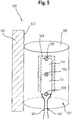
- Fig. 5 shows a view of a liquid tank with a radiator according to a second embodiment.
- the heater 135 is formed as a cylinder, which in a in Fig. 5 not shown cylindrical indentation 123 of the liquid tank 100 is inserted and at a Wölbungswandung 133 of the liquid tank 100 rests gap-free to ensure a loss-free heat transfer from the heater 135 to the Wölbungswandung 133.
- the heating element 135 comprises electrical heating elements 139, which are designed in particular as PTC heating elements.
- the electric heaters 139 are arranged on guide members 141 and connected by electric power lines 143 to an electric power supply to supply electric power to the electric heater 139 for heating.
- the heater 135 may include a heat-conductive plastic 137 to ensure an effective heat-conducting connection between the heater 135 and the Dölbungswandung 133.
- the heat-conducting plastic 137 may in particular heat-conductive fillers, such. Metal particles.
- the heating element 135 has a metallic heat-conducting element 145, which in particular comprises an aluminum heat-conducting sheet.
- the metallic heat-conducting element 145 is in particular thermally connected to the heating element 139 in order to effectively dissipate heat generated by the heating element 139 and to transfer it to the heat-conducting plastic 137 of the heating element 135.
Landscapes
- Engineering & Computer Science (AREA)
- Chemical & Material Sciences (AREA)
- Mechanical Engineering (AREA)
- Combustion & Propulsion (AREA)
- Chemical Kinetics & Catalysis (AREA)
- Transportation (AREA)
- Sustainable Energy (AREA)
- Life Sciences & Earth Sciences (AREA)
- Sustainable Development (AREA)
- Health & Medical Sciences (AREA)
- Toxicology (AREA)
- General Engineering & Computer Science (AREA)
- Exhaust Gas After Treatment (AREA)
Abstract
Description
- Die vorliegende Erfindung betrifft einen Flüssigkeitstank mit einem Heizkörper in einem Kraftfahrzeug. Die vorliegende Erfindung betrifft insbesondere einen Harnstofftank zur Aufnahme einer wässrigen Harnstoff-Lösung mit einem Heizkörper in einem Kraftfahrzeug.
- Um die Emission von Stickoxiden beim Betrieb von Verbrennungsmotoren, insbesondere Dieselmotoren, in einem Kraftfahrzeug zu reduzieren, wird das Verfahren der selektiven katalytischen Reduktion (SCR) angewendet, wobei wässrige Harnstofflösung einem Abgasstrang des Kraftfahrzeugs zugeführt wird. Die bereitzustellende Harnstofflösung kann hierbei in einem Flüssigkeitstank aufgenommen werden. Da der Gefrierpunkt der hierbei verwendeten Harnstofflösung bei ca. -11 °C liegt, muss die Harnstofflösung im Flüssigkeitstank bei geringen Außentemperaturen beheizt werden, um ein Gefrieren der Harnstofflösung zu verhindern. Aus diesem Grund können innerhalb eines Flüssigkeitstanks Heizkörper positioniert werden, um die Harnstofflösung zu erwärmen. Jedoch ist das Einbringen von Heizkörpern in einen Innenraum des Flüssigkeitstanks durch die Geometrie des Flüssigkeitstanks und die Montagemöglichkeiten beschränkt und der Heizkörper kann durch die Harnstofflösung in dem Flüssigkeitstank beschädigt werden.
- Die Druckschrift
DE 8 615 526 U1 beschreibt einen Brennstofftank aus Kunststoff für Fahrzeuge. Der Brennstofftank umfasst zwei Halbschalen, die entsprechend eine obere Halbschale und eine untere Bodenhalbschale des Brennstofftanks bilden. Der Brennstofftank weist jedoch keinen Heizkörper zum Erwärmen des Brennstofftanks auf. - Es ist die der Erfindung zugrundeliegende Aufgabe, einen Flüssigkeitstank mit einem Heizkörper anzugeben, welcher vorteilhaft an dem Flüssigkeitstank angeordnet ist.
- Diese Aufgabe wird durch den Gegenstand mit den Merkmalen nach dem unabhängigen Anspruch gelöst. Vorteilhafte Ausführungsformen der Erfindung sind Gegenstand der Figuren, der Beschreibung und der abhängigen Ansprüche.
- Gemäß einem Aspekt der Erfindung wird die Aufgabe durch einen Flüssigkeitstank zur Aufnahme von Flüssigkeit in einem Kraftfahrzeug gelöst, mit einer Flüssigkeitstankschale, wobei in der Flüssigkeitstankschale eine Einwölbung gebildet ist, welche von einem Außenbereich der Flüssigkeitstankschale zugänglich ist, und einem Heizkörper, welcher in der Einwölbung angeordnet ist, und welcher ausgebildet ist, die Flüssigkeitstankschale zu erwärmen.
- Der Flüssigkeitstank ist insbesondere als ein Harnstofftank zur Aufnahme einer wässrigen Harnstofflösung ausgebildet und umfasst insbesondere einen Additiv-Tank oder einen SCR-Tank.
- Durch den in der Einwölbung angeordneten Heizkörper wird der technische Vorteil erreicht, dass die Flüssigkeitstankschale, bzw. Tankblase, und damit die sich in dem Flüssigkeitstank, bzw. Tankblase, befindende Flüssigkeit wirksam erwärmt werden kann. Zudem ermöglicht die von dem Außenbereich der Flüssigkeitstankschale zugängliche Einwölbung der Flüssigkeitstankschale, dass der Heizkörper nach dem Fertigen des Flüssigkeitstanks von außen wirksam und einfach in die Einwölbung eingeschoben und in der Einwölbung aufgenommen werden kann. Somit muss der Heizkörper nicht in einem Innenraum des Flüssigkeitstanks positioniert werden, um die Flüssigkeit in dem Flüssigkeitstank zu erwärmen.
- Die Einwölbung der Flüssigkeitstankschale, welche von dem Außenbereich der Flüssigkeitstankschale zugänglich ist, bildet somit in dem Innenraum des Flüssigkeitstanks eine Auswölbung, die von Flüssigkeit in dem Flüssigkeitstank umgeben ist. Dadurch wird eine wirksame Wärmeübertragung von dem Heizkörper auf die sich in den Innenraum der Flüssigkeitstankschale erstreckende Auswölbung und von dort auf die Flüssigkeit in dem Flüssigkeitstank ermöglicht. Da der Heizkörper von außen in die Einwölbung eingeschoben wird, steht der Heizkörper nicht in direktem Kontakt mit der Flüssigkeit in dem Flüssigkeitstank, so dass z.B. elektrische Kurzschlüsse in dem Heizkörper, Harnstoffablagerungen an dem Heizkörper, und/oder Beschädigungen des Heizkörpers verhindert werden können.
- Insbesondere ist die Einwölbung an einer Unterseite der Flüssigkeitstankschale angeordnet, wodurch der Heizkörper sich an der Unterseite der Flüssigkeitstankschale aufgrund der Schwerkraft in dem Flüssigkeitstank sammelnde Flüssigkeit wirksam erwärmen kann.
- In einer vorteilhaften Ausführungsform ist der Heizkörper wärmeleitend mit einer Wölbungswandung der Einwölbung verbunden, um die Wölbungswandung wirksam zu erwärmen, wobei der Heizkörper insbesondere kraftschlüssig, formschlüssig oder stoffschlüssig an der Wölbungswandung anliegt.
- Dadurch wird beispielsweise der technische Vorteil erreicht, dass eine wirksame Wärmetragung von dem Heizkörper auf die Wölbungswandung und von dort auf die Flüssigkeit in dem Flüssigkeitstank sichergestellt werden kann. Hierbei ermöglicht das kraftschlüssige, formschlüssige oder stoffschlüssige Anliegen des Heizkörpers an der Wölbungswandung eine besonders wirksame Wärmeübertragung.
- In einer weiteren vorteilhaften Ausführungsform weist der Heizkörper einen wärmeleitenden Kunststoff auf, um eine wärmeleitende Verbindung zwischen dem Heizkörper und der Flüssigkeitstankschale bereitzustellen, wobei der wärmeleitende Kunststoff insbesondere ein Elastomer oder ein thermoplastisches Elastomer umfasst.
- Dadurch wird beispielsweise der technische Vorteil erreicht, dass durch den wärmeleitenden Kunststoff eine wirksame Wärmeübertragung von dem Heizkörper über den wärmeleitenden Kunststoff auf die Flüssigkeitstankschale sichergestellt werden kann. Der wärmeleitende Kunststoff kann insbesondere ein Elastomer oder ein thermoplastisches Elastomer, u.a. einen elastisch verformbaren Kunststoff, umfassen. Durch die elastische Verformbarkeit des wärmeleitenden Kunststoffs wird sichergestellt, dass sich der Heizkörper an die Kontur der Einwölbung anpasst, wodurch sichergestellt werden kann, dass der Heizkörper in der Einwölbung wirksam aufgenommen ist. Dadurch kann z.B. das Auftreten von Luftspalten zwischen dem Heizkörper und der Einwölbung, welche eine wirksame Wärmeübertragung beeinträchtigen können, verhindert werden.
- In einer weiteren vorteilhaften Ausführungsform umfasst der wärmeleitende Kunststoff wärmeleitende Füllstoffe.
- Durch die wärmeleitenden Füllstoffe, insbesondere Metallpartikel, können besonders wirksame Wärmeleiteigenschaften des wärmeleitenden Kunststoffs sichergestellt werden.
- In einer weiteren vorteilhaften Ausführungsform weist der Heizkörper ein metallisches Wärmeleitelement auf, um eine wärmeleitende Verbindung von dem Heizkörper über das metallische Wärmeleitelement an die Flüssigkeitstankschale bereitzustellen, insbesondere über den wärmeleitenden Kunststoff bereitzustellen, und wobei das metallische Wärmeleitelement insbesondere ein Aluminium-Wärmeleitblech umfasst.
- Dadurch wird beispielsweise der technische Vorteil erreicht, dass durch das metallische Wärmeleitelement, insbesondere Aluminium-Wärmeleitblech, die Wärmeübertragung insgesamt zwischen dem Heizkörper und der Flüssigkeitstankschale verbessert werden kann. Hierbei wird Wärme von einem Heizelement des Heizkörpers an das metallische Wärmeleitelement wirksam abgegeben, wobei das metallische Wärmeleitelement die aufgenommene Wärme wirksam an die Flüssigkeitstankschale weiterleitet, insbesondere über den wärmeleitenden Kunststoff an die Flüssigkeitstankschale weiterleitet.
- In einer weiteren vorteilhaften Ausführungsform weist der Heizkörper ein elektrisches Heizelement zum Erwärmen des Heizkörpers auf, wobei das elektrische Heizelement als ein elektrisches Widerstands-Heizelement ausgebildet ist.
- Dadurch wird beispielsweise der technische Vorteil erreicht, dass das elektrische Widerstands-Heizelement wirksam mit einer elektrischen Stromversorgung verbunden werden kann, um den Heizkörper zu erwärmen.
- In einer weiteren vorteilhaften Ausführungsform weist der Heizkörper ein elektrisches Heizelement zum Erwärmen des Heizkörpers aufweist, wobei das elektrische Heizelement als ein PTC-Heizelement ausgebildet ist.
- Dadurch wird beispielsweise der technische Vorteil erreicht, dass ein PTC-Heizelement, eine besonders wirksame Erwärmung des Heizkörpers ermöglicht. Ein PTC-Heizelement weist darüber hinaus den Vorteil auf, dass es eine eigenständige Regelfunktion der Heizleistung umfasst, so dass eine übermäßig starke Erwärmung des Heizelements vermieden werden kann. Insbesondere kann in dem Heizkörper ein oder mehrere PTC-Heizelemente mit einem oder mehreren elektrischen Widerstands-Heizelementen kombiniert sein.
- In einer weiteren vorteilhaften Ausführungsform ist die Einwölbung als eine zylinderförmige Einwölbung ausgebildet und ist der Heizkörper als ein Zylinder ausgebildet, welcher in die zylinderförmige Einwölbung eingeführt ist, oder ist die Einwölbung als eine konusförmige Einwölbung ausgebildet, und ist der Heizkörper als ein Konus ausgebildet, welcher in die konusförmige Einwölbung eingeführt ist.
- Dadurch wird beispielsweise der technische Vorteil erreicht, dass die Ausbildung des Heizkörpers als ein Zylinder oder Konus zum Einführen in eine entsprechende zylinderförmige oder konusförmige Einwölbung ein wirksames passgenaues Anpassen der Geometrie des Heizkörpers an die Geometrie der Einwölbung ermöglicht wird. Wenn der Heizkörper als ein Konus ausgebildet ist, kann der Heizkörper besonders wirksam die Einwölbung mit Druck beaufschlagen und dadurch Luftspalte zwischen dem Heizkörper und der Einwölbung verhindern.
- In einer weiteren vorteilhaften Ausführungsform weist der Flüssigkeitstank einen Verschluss auf, welcher ausgebildet ist, die Einwölbung mit dem darin aufgenommenen Heizkörper zu verschließen, wobei insbesondere zwischen dem Verschluss und dem Heizkörper ein elastisches Element, insbesondere eine Verschlussfeder, angeordnet ist, welches ausgebildet ist, den Heizkörper mit einer Kraft zu beaufschlagen, um den Heizkörper in der Einwölbung in wärmeleitendem Kontakt zu fixieren.
- Dadurch wird beispielsweise der technische Vorteil erreicht, dass durch den Verschluss eine vorteilhafte Positionierung des Heizkörpers in der Einwölbung sichergestellt werden kann, und insbesondere das elastische Element den Heizkörper vorteilhaft in der Einwölbung in wärmeleitendem Kontakt fixiert.
- In einer weiteren vorteilhaften Ausführungsform ist in der Flüssigkeitstankschale eine weitere Einwölbung gebildet, welche von dem Außenbereich der Flüssigkeitstankschale zugänglich ist und wobei der Flüssigkeitstank einen weiteren Heizkörper, welcher in der weiteren Einwölbung angeordnet ist, aufweist, wobei der weitere Heizkörper ausgebildet ist, die Flüssigkeitstankschale zu erwärmen, und wobei die Einwölbung und die weitere Einwölbung insbesondere an einer Unterseite der Flüssigkeitstankschale angeordnet sind.
- Dadurch wird beispielsweise der technische Vorteil erreicht, dass durch den weiteren Heizkörper eine größere Heizleistung bereitgestellt werden kann, als wenn nur ein einziger Heizkörper verwendet wird. Insbesondere können mehrere weitere Einwölbungen zur Aufnahme von mehreren weiteren Heizkörpern an dem Flüssigkeitstank angeordnet sein. Dadurch dass, die Einwölbung und die weitere Einwölbung insbesondere an der Unterseite der Flüssigkeitstankschale angeordnet sind, können die Heizkörper die Unterseite der Flüssigkeitstankschale besonders wirksam erwärmen. Da sich in dem Flüssigkeitstank befindliche Flüssigkeit aufgrund der Schwerkraft an der Unterseite der Flüssigkeitstankschale sammelt, kann hierdurch eine besonders wirksame Erwärmung der Flüssigkeit in dem Flüssigkeitstank sichergestellt werden.
- In einer weiteren vorteilhaften Ausführungsform umfasst die Flüssigkeitstankschale eine erste Flüssigkeitstankhalbschale mit einem ersten Verbindungselement, das sich von einer ersten Innenwandung der ersten Flüssigkeitstankhalbschale in einen Innenraum des Flüssigkeitstanks erstreckt, und wobei die Flüssigkeitstankschale eine zweite Flüssigkeitstankhalbschale mit einem zweiten Verbindungselement umfasst, das sich von einer zweiten Innenwandung der zweiten Flüssigkeitstankhalbschale in den Innenraum des Flüssigkeitstanks erstreckt, wobei das erste Verbindungselement und das zweite Verbindungselement im Innenraum des Flüssigkeitstanks miteinander verbunden sind, und wobei sich die Einwölbung von dem Außenbereich der Flüssigkeitstankschale in das erste Verbindungselement oder in das zweite Verbindungselement erstreckt, und wobei das erste Verbindungselement und/oder das zweite Verbindungselement insbesondere ein säulenförmiger Abschnitt der ersten Flüssigkeitstankhalbschale und/oder der zweiten Flüssigkeitstankhalbschale ist.
- Dadurch wird beispielsweise der technische Vorteil erreicht, dass die Verbindungselemente eine stabile Verbindung zwischen den Flüssigkeitstankhalbschalen des Flüssigkeitstanks sicherstellen. Dadurch, dass sich die Einwölbung von dem Außenbereich der Flüssigkeitstankschale in das erste Verbindungselement oder in das zweite Verbindungselement erstreckt, dient das jeweilige Verbindungselement zudem zur Aufnahme des Heizkörpers, der von dem Außenbereich der Flüssigkeitstankschale in die sich in das jeweilige Verbindungselement erstreckende Einwölbung eingeschoben wird. Da das jeweilige Verbindungselement die Einwölbung aufweist, müssen keine weiteren Einwölbungen an der Flüssigkeitstankschale angeordnet werden, was die Fertigung des Flüssigkeitstanks vereinfacht. Hierbei können die Flüssigkeitstankhalbschalen jeweils mit mehreren Verbindungselementen ausgebildet sein, die jeweils eine Einwölbung aufweisen können, in welche jeweils ein Heizkörper eingeführt werden kann. Das säulenförmige erste und/oder zweite Verbindungselement kann insbesondere eine zylindrische, konische oder sternförmige, Ausbildung aufweisen und dadurch stabile Verbindungselemente mit einer Einwölbung sicherstellen.
- In einer weiteren vorteilhaften Ausführungsform weist das erste Verbindungselement eine erste Kontaktfläche auf, weist das zweite Verbindungselement eine zweite Kontaktfläche auf, und ist die erste Kontaktfläche an der zweiten Kontaktfläche befestigbar, um das erste Verbindungselement mit dem zweiten Verbindungselement zu verbinden.
- Dadurch wird beispielsweise der technische Vorteil erreicht, dass eine stabile Verbindung zwischen der ersten und zweiten Flüssigkeitstankhalbschale sichergestellt wird.
- In einer weiteren vorteilhaften Ausführungsform sind die erste Kontaktfläche und die zweite Kontaktfläche miteinander verschweißt oder verklebt, und wobei zumindest eine der Kontaktflächen insbesondere eine Vertiefung zum Aufnehmen eines Schweiß,- oder Klebstoffaustriebs umfasst.
- Dadurch wird beispielsweise der technische Vorteil erreicht, dass eine großflächige und stabile Verbindung zwischen dem ersten Verbindungselement und dem zweiten Verbindungselement bereitgestellt werden kann.
- In einer weiteren vorteilhaften Ausführungsform weist die erste Flüssigkeitstankhalbschale erste Stabilisierungselemente zum Stabilisieren des ersten Verbindungselements an der ersten Innenwandung aufweist und/oder weist die zweite Flüssigkeitstankhalbschale zweite Stabilisierungselemente zum Stabilisieren des zweiten Verbindungselements an der zweiten Innenwandung auf, wobei die ersten Stabilisierungselemente und die zweiten Stabilisierungselemente insbesondere als Stabilisierungsrippen und/oder Stabilisierungssicken ausgebildet sind.
- Dadurch wird beispielsweise der technische Vorteil erreicht, dass sich durch die Stabilisierungselemente die Stabilität der Verbindungselemente an den Flüssigkeitstankhalbschalen erhöht, wodurch sich die Festigkeit des Flüssigkeitstanks noch weiter verbessert. Eine Stabilisierungsrippe umfasst hierbei eine längliche Erhöhung an dem Übergangsbereich zwischen dem jeweiligen Verbindungselement und der jeweiligen Flüssigkeitstankhalbschale. Eine Stabilisierungssicke ist hierbei eine rillenförmige Verdickung zwischen dem jeweiligen Verbindungselement und der jeweiligen Flüssigkeitstankhalbschale.
- In einer weiteren vorteilhaften Ausführungsform sind die ersten Stabilisierungselemente und die zweiten Stabilisierungselemente an einer dem Innenraum des Flüssigkeitstanks zugewandten Innenseite des jeweiligen Verbindungselements oder sind an der dem Außenbereich des Flüssigkeitstanks zugewandten Außenseite des jeweiligen Verbindungselements angeordnet, und wobei sich die ersten Stabilisierungselemente und die zweiten Stabilisierungselemente entlang einer Längsrichtung des jeweiligen Verbindungselements erstrecken oder die ersten Stabilisierungselemente und die zweiten Stabilisierungselemente sternförmig oder radial umlaufend an dem jeweiligen Verbindungselement angeordnet sind.
- Dadurch wird beispielsweise der technische Vorteil erreicht, dass ein Anordnen der Stabilisierungselemente an der Außenseite oder Innenseite der entsprechenden Verbindungselemente eine wirksame Stabilisierung der Verbindungselemente an der Flüssigkeitstankschale sicherstellt.
- In einer weiteren vorteilhaften Ausführungsform sind die erste Flüssigkeitstankhalbschale und das erste Verbindungselement einstückig durch ein Spritzgussteil, insbesondere Kunststoffformteil, gebildet und/oder sind die zweite Flüssigkeitstankhalbschale und das zweite Verbindungselement einstückig durch ein Spritzgussteil, insbesondere Kunststoffformteil, gebildet.
- Dadurch wird beispielsweise der technische Vorteil erreicht, dass sich die Verbindungselemente mit einem geringen Volumen herstellen lassen und sich das Volumen des Flüssigkeitstanks erhöht, dass sich eine gute Krafteinleitung von dem Verbindungselement auf die Flüssigkeitstankhalbschale erzielen lässt und die Flüssigkeitstankschale zusammen mit dem Verbindungselement in einem Arbeitsgang hergestellt werden kann.
- In einer weiteren vorteilhaften Ausführungsform weist der Flüssigkeitstank eine Schwallwand zum Hemmen einer Flüssigkeitsbewegung in dem Flüssigkeitstank auf. Dadurch wird beispielsweise der technische Vorteil erreicht, dass eine Schwallwand ein wirksames Hemmen der Flüssigkeitsbewegung sicherstellt
- Ausführungsbeispiele der Erfindung sind in den Zeichnungen dargestellt und werden im Folgenden näher beschrieben.
- Es zeigen:
- Fig. 1
- eine schematische Ansicht eines Flüssigkeitstanks mit einer Flüssigkeitstankschale;
- Fig. 2
- eine Ansicht eines Flüssigkeitstanks mit einer Flüssigkeitstankschale;
- Fig. 3
- eine Ansicht eines Flüssigkeitstanks mit einer Flüssigkeitstankschale und einem in einer Einwölbung der Flüssigkeitstankschale aufgenommenen Heizkörper;
- Fig. 4
- eine Ansicht eines Flüssigkeitstanks mit einem Heizkörper gemäß einer ersten Ausführungsform; und
- Fig. 5
- eine Ansicht eines Flüssigkeitstanks mit einem Heizkörper gemäß einer zweiten Ausführungsform.
-
Fig. 1 zeigt eine schematische Ansicht eines Flüssigkeitstanks zur Aufnahme von Flüssigkeit mit einer Flüssigkeitstankschale. Der Flüssigkeitstank 100 ist insbesondere als ein Harnstofftank zur Aufnahme von wässriger Harnstofflösung ausgebildet. Um die Emission von Stickoxiden beim Betrieb von Verbrennungsmotoren, insbesondere Dieselmotoren, in einem Kraftfahrzeug zu reduzieren, wird das Verfahren der selektiven katalytischen Reduktion (SCR) angewendet, wobei die Harnstofflösung einem Abgasstrang des Kraftfahrzeugs zugeführt wird. Die bereitzustellende Harnstofflösung kann hierbei in dem Flüssigkeitstank 100 aufgenommen werden. Da der Gefrierpunkt der hierbei verwendeten Harnstofflösung bei ca. -11 °C liegt, muss die Harnstofflösung bei geringen Außentemperaturen im Harnstofftank beheizt werden, um ein Einfrieren der Harnstofflösung zu verhindern. - Der in
Fig. 1 dargestellte Flüssigkeitstank 100 weist eine Flüssigkeitstankschale 101 auf, welche aus einer unteren, ersten Flüssigkeitstankhalbschale 102 und einer oberen, zweiten Flüssigkeitstankhalbschale 107 gebildet ist. Die erste Flüssigkeitstankhalbschale 102 umfasst ein erstes Verbindungselement 103, das sich von einer ersten Innenwandung 105 der ersten Flüssigkeitstankhalbschale 102 in einen Innenraum 106 des Flüssigkeitstanks 100 erstreckt. Die zweite Flüssigkeitstankhalbschale 107 umfasst ein zweites Verbindungselement 109, das sich von einer zweiten Innenwandung 111 der zweiten Flüssigkeitstankhalbschale 107 in den Innenraum 106 des Flüssigkeitstanks 100 erstreckt. - Bei der Herstellung des Flüssigkeitstanks 100 werden die zweite Flüssigkeitstankhalbschale 107 und die erste Flüssigkeitstankhalbschale 102 zusammengesetzt und an ihren Rändern miteinander verbunden. Dabei kommt eine erste Kontaktfläche 113 des ersten Verbindungselementes 103 mit einer zweiten Kontaktfläche 115 des zweiten Verbindungselementes 109 in Berührung. Die erste und die zweite Kontaktfläche 113 und 115 werden miteinander verschweißt oder verklebt. Dadurch wird eine mechanisch feste Verbindung zwischen dem ersten Verbindungselement 103 und dem zweiten Verbindungselement 109 erreicht und die Festigkeit des Flüssigkeitstanks 100 verbessert sich.
- Die Verbindung des ersten und des zweiten Verbindungselementes 103 und 109 kann im Allgemeinen auch auf anderem Wege erfolgen. Beispielsweise können das erste oder das zweite Verbindungselement 103 oder 109 auch ein Rastmittel umfassen, das beim Zusammensetzen der ersten und der zweiten Flüssigkeitstankhalbschale 102 und 107 in dem entgegengesetzten zweiten oder ersten Verbindungselement 109 oder 103 einrastet. Im Allgemeinen können alle Ausgestaltungen verwendet werden, die es erlauben eine mechanisch feste Verbindung zwischen dem ersten Verbindungselement 103 und dem zweiten Verbindungselement 109 herzustellen, wobei auch definierte Bewegungen bis zum Anschlag in einer Richtung zugelassen werden.
- Wie in
Fig. 1 dargestellt ist, weisen die erste Kontaktfläche 113 und die zweite Kontaktfläche 115 jeweils eine Vertiefung 117 auf, welche ausgebildet ist, einen Schweiß,- oder Klebstoffauftrieb aufzunehmen, welcher bei Verschweißen oder Verkleben der ersten Kontaktfläche 113 mit der zweiten Kontaktfläche 115 gebildet wird. Die Vertiefungen 117 können als ein konzentrischer Kreis, mehrere konzentrische Kreise oder als kreuzförmige Vertiefungen 117 auf der ersten Kontaktfläche 113 oder zweiten Kontaktfläche 115 angeordnet sein. In den Vertiefungen 117 wird bei einem Schmelz- und Anpressvorgang verdrängtes Material aufgenommen, so dass die Festigkeit der Verbindungsstelle verbessert wird. - Wie in
Fig. 1 dargestellt ist, weist die erste Flüssigkeitstankhalbschale 102 erste Stabilisierungselemente 119 auf, welche ausgebildet sind das erste Verbindungselement 103 an der ersten Innenwandung 105 der ersten Flüssigkeitstankhalbschale 102 zu stabilisieren, und weist die zweite Flüssigkeitstankhalbschale 107 zweite Stabilisierungselemente 121 auf, welche ausgebildet sind das zweite Verbindungselement 109 an der zweiten Innenwandung 111 der zweiten Flüssigkeitstankhalbschale 107 zu stabilisieren. Die Stabilisierungselemente 119, 121 sind hierbei als Stabilisierungsrippen ausgebildet, können aber auch als Stabilisierungssicken ausgebildet sein. Die Stabilisierungselemente 119, 121 sind an einer dem Innenraum 106 des Flüssigkeitstanks 100 zugewandten Innenseite des jeweiligen Verbindungselements 103, 109 oder an einer einem Außenbereich 122 des Flüssigkeitstanks 100 zugewandten Außenseite des jeweiligen Verbindungselements 103, 109 angeordnet. Die Stabilisierungselemente 119, 121 erstrecken sich entlang einer Längsrichtung des jeweiligen Verbindungselements 103, 109 und/oder die Stabilisierungselemente 119, 121 sind sternförmig oder radial umlaufend an dem jeweiligen Verbindungselement 103, 109 angeordnet. - In der Flüssigkeitstankschale 101 ist eine Einwölbung 123 und eine weitere Einwölbung 125 gebildet, welche, wie in
Fig. 1 nicht dargestellt ist, von dem Außenbereich 122 des Flüssigkeitstanks 100 aus zugänglich ist. Ein inFig. 1 nicht dargestellter Heizkörper kann in der Einwölbung 123, bzw. der weiteren Einwölbung 125, angeordnet sein, um die Flüssigkeitstankschale 101 zu erwärmen. Wie inFig. 1 nicht dargestellt ist, kann die Einwölbung 123 und/oder die weitere Einwölbung 125 als eine zylinderförmige Einwölbung 123 oder eine konusförmige Einwölbung 123 ausgebildet sein, wobei der Heizkörper als ein Zylinder oder ein Konus ausgebildet ist, welcher in die entsprechende zylinderförmige Einwölbung 123, bzw. konusförmige Einwölbung 123 eingeführt ist. Hierbei kann auch ein weiterer Heizkörper in der weiteren Einwölbung 125 aufgenommen sein. - Wie in
Fig. 1 dargestellt ist, erstreckt sich die Einwölbung 123 von dem Außenbereich 122 der Flüssigkeitsschale 101 in das erste Verbindungselement 103 und erstreckt sich die weitere Einwölbung 125 in das zweite Verbindungselement 109. Das erste und/oder zweite Verbindungselement 103, 109 ist hierbei als ein säulenförmiges Verbindungselement 103, 109 ausgebildet und kann hierbei eine zylindrische Form, eine konische Form oder auch einen sternförmigen Querschnitt aufweisen. - Alternativ kann auch nur das erste Verbindungelement 103 mit einer Einwölbung 123 gebildet sein oder kann auch nur das zweite Verbindungselement 109 mit einer weiteren Einwölbung 125 gebildet sein. In der Einwölbung 123 und/oder der weiteren Einwölbung 125 kann jeweils ein in
Fig. 1 nicht dargestellter Heizkörper, bzw. weiterer Heizkörper zum Erwärmen der Flüssigkeitstankschale 101 angeordnet sein. -
Fig. 2 zeigt eine Ansicht eines Flüssigkeitstanks mit einer Flüssigkeitstankschale. Der Flüssigkeitstank 100 ist beispielsweise ein Tank für eine wässrige Harnstofflösung in einem Fahrzeug. Die Flüssigkeitstankschale 101 umfasst eine erste und zweite Flüssigkeitstankhalbschale 102 und 107, welche beispielsweise Kunststoffformteile sind, die im Spritzgussverfahren hergestellt sind. Hierbei ist die erste Flüssigkeitstankhalbschale 102 und das erste Verbindungselement 103 insbesondere einstückig gebildet und ist die zweite Flüssigkeitstankhalbschale 107 und das zweite Verbindungselement 109 insbesondere einstückig gebildet. Die Kunststoffe können beispielsweise Polyolefine wie Polyethylen oder Polypropylen, Polyamid oder Polyoxymethylen (POM), insbesondere hochdichtes Polyethylen (HDPE) umfassen. - Die beiden Flüssigkeitstankhalbschalen 102 und 107 sind im Randbereich miteinander verklebt oder verschweißt und bilden im Innenraum 106 des Flüssigkeitstanks 100 einen Flüssigkeitshohlraum, in den die Flüssigkeit gefüllt werden kann. Der Flüssigkeitstank 100 weist hierzu einen Einfüllstutzen 127 auf, über den die Flüssigkeit in den Flüssigkeitstank 100 eingefüllt werden kann.
- Durch die Verwendung einer Spritzgussformtechnik können die Flüssigkeitstankhalbschalen 102 und 107 gewichts- und kostenoptimiert hergestellt werden, beispielsweise durch eine genaue Definition der benötigten Wandstärken. Daneben können ohne zusätzliche Fertigungsschritte Bauteile wie Pumpenflansche, Stutzen, Halterungen integriert werden. Im Tankinneren wird eine deutlich vereinfachte Montage erreicht, da durch die offenen Flüssigkeitstankhalbschalen 102 und 107 eine gute Zugänglichkeit gewährleistet wird.
- Die Festigkeit der Flüssigkeitstanks 100 lässt sich durch Anpassung einer Anordnung und Gestaltung von Stabilisierungselemente 119, 121 und Schwallwänden gezielt lokal beeinflussen. Die Herstellung der Flüssigkeitstankhalbschalen 102 und 107 im Spritzgussverfahren ist besonders vorteilhaft, da sich hierdurch die Verbindungselemente 103 und 109 im Gegensatz zur Herstellung im Blasformverfahren mit einem geringen Volumen herstellen lassen. Dadurch vergrößert sich das Volumen des Flüssigkeitstanks 100.
- Der in
Fig. 2 dargestellte Flüssigkeitstank 100 umfasst drei Stellen, an denen die Verbindungselemente 103, 109 innerhalb eines inFig. 2 nicht dargestellten Innenraums 106 des Flüssigkeitstanks 100 angeordnet sind. Die zweiten Verbindungselemente 109 sind einstückig in die zweite Flüssigkeitstankhalbschale 107 integriert und bilden jeweils an einer zweiten Außenwandung 129 eine weitere Einwölbung 125, die von einem Außenbereich 122 der Flüssigkeitstankschale 101 her zugänglich ist. Wie inFig. 2 nicht dargestellt ist, sind die ersten Verbindungselemente 103 einstückig in die erste Flüssigkeitstankhalbschale 102 integriert und weisen an einer ersten Außenwandung 131 jeweils eine Einwölbung 123 auf, die ebenfalls von dem Außenbereich 122 der ersten Flüssigkeitstankhalbschale 102 her zugänglich ist. Dadurch können das erste Verbindungselement 103 und das zweite Verbindungselement 109 nach dem Zusammensetzen der Flüssigkeitstankhalbschalen 102, 107 miteinander verbunden werden, beispielsweise durch Verschweißen oder Verschrauben und inFig. 2 nicht dargestellte Heizkörper können in die Einwölbung 123 und/oder die weitere Einwölbung 125 eingebracht werden. -
Fig. 3 zeigt eine Ansicht eines Flüssigkeitstanks mit einer Flüssigkeitstankschale und einem in einer Einwölbung der Flüssigkeitstankschale aufgenommenen Heizkörper. Die inFig. 3 schematisch dargestellte ersten und zweiten Flüssigkeitstankhalbschale 102, 107 weisen eine erste Innenwandung 105 und eine erste Außenwandung 131, sowie eine zweite Innenwandung 111 und eine zweite Außenwandung 129 auf. Ein erstes Verbindungselement 103 erstreckt sich von der ersten Innenwandung 105 und ein zweites Verbindungselement 109 erstreckt sich von der zweiten Innenwandung 111 in den Innenraum 106 des Flüssigkeitstanks 100. - Eine erste Kontaktfläche 113 des ersten Verbindungselements 103 ist an einer zweiten Kontaktfläche 115 des zweiten Verbindungselements 109 befestigt. Die erste und zweiten Kontaktflächen 113, 115 sind insbesondere miteinander verschweißt oder verklebt. Eine optionale Vertiefung 117 der ersten und/oder zweiten Kontaktfläche 113, 115 zur Aufnahme des Schweiß,- und/oder Klebstoffaustriebs ist in
Fig. 3 nicht dargestellt. - Das erste und zweite Verbindungselement 103, 109 sind als säulenförmige Abschnitte der ersten und zweiten Flüssigkeitstankhalbschale 102, 107 ausgebildet und weisen eine konische Form auf. Eine Einwölbung 123 der ersten Flüssigkeitstankhalbschale 102 erstreckt sich in das erste Verbindungselement 103 und eine weitere Einwölbung 125 der zweiten Flüssigkeitstankhalbschale 107 erstreckt sich in das zweite Verbindungselement 109. Die Einwölbung 123, bzw. weitere Einwölbung 125 sind jeweils durch eine Wölbungswandung 133 begrenzt.
- In der Einwölbung 123 des ersten Verbindungselements 103 ist ein Heizkörper 135 angeordnet, welcher ausgebildet ist, das erste Verbindungselement 103 zu erwärmen, und welcher insbesondere als eine Heizpatrone ausgebildet ist. Der Heizkörper 135 liegt hierbei an der Wölbungswandung 133, insbesondere kraftschlüssig, formschlüssig oder stoffschlüssig, an. Der Heizkörper 135 umfasst ein elektrisches Heizelement 139, welches insbesondere als ein elektrisches Widerstandsheizelement ausgebildet ist, aber alternativ auch als ein PTC-Heizelement ausgebildet sein kann. Wie in
Fig. 3 nicht dargestellt, ist das elektrische Heizelement 139 insbesondere mit einer elektrischen Stromversorgung angeschlossen, um dem elektrischen Heizelement 139 elektrische Energie zum Erwärmen des ersten Verbindungselements 103 zuzuführen. - Der Heizkörper 135 kann einen wärmeleitende Kunststoff 137 aufweisen, um eine wirksame wärmeleitende Verbindung zwischen dem Heizkörper 135 und der Wölbungswandung 133 sicherzustellen. Um einen besonders wirksamen Wärmeübergang von dem Heizelement 139 auf die Wölbungswandung 133 sicherzustellen, kann der wärmeleitender Kunststoff 137 insbesondere wärmeleitende Füllstoffe, wie z.B. Metallpartikel, umfassen. Der wärmeleitende Kunststoff 137 kann insbesondere ein Elastomer oder ein thermoplastisches Elastomer umfassen, bzw. elastisch verformbare Eigenschaften aufweisen, welche ein wirksames Einpassen des Heizkörpers 135 in die Einwölbung 123 sicherstellen. Zudem stellt der wärmeleitende Kunststoff 137 eine elektrische Isolation zwischen dem Heizkörper 135 und dem ersten Verbindungselement 103 bereit. Um einen besonders wirksamen Wärmeübergang zu gewährleisten kann der Heizkörper 135 insbesondere ein in
Fig. 3 nicht dargestelltes metallisches Wärmeleitelement aufweisen, wobei das metallische Wärmeleitelement insbesondere ein Aluminium-Wärmeleitblech umfasst. - Der Heizkörper 135, insbesondere die Heizpatrone, kann hierbei von dem Außenbereich 122 des Flüssigkeitstanks 100 aus in die Einwölbung 123 der ersten Flüssigkeitshalbschale 102 einschoben werden und wirksam in der Einwölbung 123 positioniert werden. Durch den wärmeleitenden Kunststoff 137 wird hierbei eine wirksame Aufnahme des Heizkörper 135 in der Einwölbung 123 sichergestellt, da sich der aus wärmeleitenden Kunststoff 137 bestehende konisch geformte Heizkörper 135 an die konische Form der Einwölbung 123 in dem ersten Verbindungselement 103 anpasst. Dadurch kann eine dichte kraftschlüssige, formschlüssige oder stoffschlüssige Verbindung zwischen dem Heizkörper 135 und der Einwölbung 123 sichergestellt werden, wodurch Spalten, bzw. Luftstellen, welche eine beeinträchtigte Wärmeübertragung verursachen können, vermieden werden.
- Wie in
Fig. 3 nicht dargestellt ist, kann der Flüssigkeitstank 100 einen Verschluss aufweisen, welcher ausgebildet ist, die Einwölbung 123 mit dem darin aufgenommenen Heizkörper 135 zu verschließen und somit eine wirksame Fixierung des Heizkörpers 135 in der Einwölbung 123 zu gewährleisten. Hierbei ist insbesondere zwischen dem Verschluss und dem Heizkörper 135 ein elastisches Element, z.B. eine Verschlussfeder, angeordnet, welche ausgebildet ist, den Heizkörper 135 mit einer Kraft zu beaufschlagen, um den Heizkörper 135 in der Einwölbung 123 zu fixieren. - In der Ausführungsform gemäß
Fig. 3 ist ein Heizkörper 135 in der Einwölbung 123 eingebracht. Ein weiterer Heizkörper kann entsprechend in der weiteren Einwölbung 125 eingebracht sein, um das zweite Verbindungselement 109 zu erwärmen. Zudem ist es alternativ möglich, dass sowohl ein Heizkörper 135 in der Einwölbung 123 eingebracht werden kann und zudem ein weiterer Heizkörper in die weitere Einwölbung 125 eingebracht werden kann, um sowohl das erste Verbindungselement 103 als auch das zweite Verbindungselement 109 zu erwärmen. - Insbesondere kann einer oder mehrere Heizkörper 135 in einer oder mehreren Einwölbungen 123 von einem oder mehreren ersten Verbindungselementen 103 aufgenommen sein, um die untere, erste Flüssigkeitstankhalbschale 102 und die darin aufgenommene Flüssigkeit wirksam zu erwärmen. Dies ist insbesondere von Vorteil, da sich in den Flüssigkeitstank 100 eingeführte Flüssigkeit nach dem Einfüllen aufgrund der Schwerkraft zuerst am Boden der ersten Flüssigkeitstankhalbschale 102 sammelt.
- Somit stellt der Heizkörper 135 eine wirksame Wärmeübertragung von dem Heizkörper 135 auf das erste Verbindungselement 103 sicher, da eine große Fläche zur Wärmeübertragung zwischen dem Heizkörper 135 und dem ersten Verbindungselement 103 gewährleistet wird. Durch den wärmeleitenden Kunststoff 137 wird sichergestellt, dass die Wärmeübertragung nicht durch unterbrochene Wärmeleitpfade, wie z.B. Lufteinschlüsse, unterbrochen ist. Ein hierbei verwendeter optional mit wärmeleitenden Füllstoffen versehener wärmeleitender Kunststoff 137 muss hierbei gute wärmeleitende Eigenschaften aufweisen, elektrisch isolierend sein, und elastische Eigenschaften aufweisen und einen dauerhaften Wärmeübergang aufweisen ohne dass Ablösungen auftreten. Hierbei sind insbesondere Elastomere oder thermoplastische Elastomere, z.B. Elastomere mit wärmeleitenden Füllstoffen, für die Verwendung als wärmeleitender Kunststoff 137 gut geeignet.
-
Fig. 4 zeigt eine Ansicht eines Flüssigkeitstanks mit einem Heizkörper gemäß einer ersten Ausführungsform. - Der Heizkörper 135 ist als ein Konus ausgebildet, welcher in eine in
Fig. 4 nicht dargestellte konusförmige Einwölbung 123 des Flüssigkeitstanks 100 eingeführt ist und an einer Wölbungswandung 133 des Flüssigkeitstanks 100 spaltfrei anliegt, um eine verlustfreie Wärmeübertragung von dem Heizkörper 135 auf die Wölbungswandung 133 sicherzustellen. - Der Heizkörper 135 umfasst elektrische Heizelemente 139, welche insbesondere als PTC-Heizelemente ausgebildet ist. Die elektrischen Heizelemente 139 sind auf Leitelementen 141 angeordnet und durch elektrische Stromleitungen 143 mit einer elektrischen Stromversorgung verbunden, um dem elektrischen Heizelement 139 elektrische Energie zum Erwärmen zuzuführen.
- Der Heizkörper 135 kann einen wärmeleitende Kunststoff 137 aufweisen, um eine wirksame wärmeleitende Verbindung zwischen dem Heizkörper 135 und der Wölbungswandung 133 sicherzustellen. Um einen besonders wirksamen Wärmeübergang zwischen dem Heizelement 139 und der Wölbungswandung 133 sicherzustellen, kann der wärmeleitende Kunststoff 137 insbesondere wärmeleitende Füllstoffe, wie z.B. Metallpartikel, umfassen.
-
Fig. 5 zeigt eine Ansicht eines Flüssigkeitstanks mit einem Heizkörper gemäß einer zweiten Ausführungsform. - Der Heizkörper 135 ist als ein Zylinder ausgebildet, welcher in eine in
Fig. 5 nicht dargestellte zylinderförmige Einwölbung 123 des Flüssigkeitstanks 100 eingeführt ist und an einer Wölbungswandung 133 des Flüssigkeitstanks 100 spaltfrei anliegt, um eine verlustfreie Wärmeübertragung von dem Heizkörper 135 auf die Wölbungswandung 133 sicherzustellen. - Der Heizkörper 135 umfasst elektrische Heizelemente 139, welche insbesondere als PTC-Heizelemente ausgebildet sind. Die elektrischen Heizelemente 139 sind auf Leitelementen 141 angeordnet und durch elektrische Stromleitungen 143 mit einer elektrischen Stromversorgung verbunden, um dem elektrischen Heizelement 139 elektrische Energie zum Erwärmen zuzuführen.
- Der Heizkörper 135 kann einen wärmeleitende Kunststoff 137 aufweisen, um eine wirksame wärmeleitende Verbindung zwischen dem Heizkörper 135 und der Wölbungswandung 133 sicherzustellen. Um einen besonders wirksamen Wärmeübergang zwischen dem Heizelement 139 und der Wölbungswandung 133 sicherzustellen, kann der wärmeleitende Kunststoff 137 insbesondere wärmeleitende Füllstoffe, wie z.B. Metallpartikel, umfassen.
- Um die Wärmeübertragung von dem Heizelement 139 auf den wärmeleitenden Kunststoff 137 zu verbessern weist der Heizkörper 135 ein metallisches Wärmeleitelement 145 auf, welches insbesondere ein Aluminium-Wärmeleitblech umfasst. Das metallische Wärmeleitelement 145 ist insbesondere mit dem Heizelement 139 thermisch verbunden, um von dem Heizelement 139 erzeugte Wärme wirksam abzuleiten und auf den wärmeleitenden Kunststoff 137 des Heizkörpers 135 zu übertragen.
- Alle in Verbindung mit einzelnen Ausführungsformen der Erfindung erläuterten und gezeigten Merkmale können in unterschiedlicher Kombination in dem erfindungsgemäßen Gegenstand vorgesehen sein, um gleichzeitig deren vorteilhafte Wirkungen zu realisieren.
- Der Schutzbereich der vorliegenden Erfindung ist durch die Ansprüche gegeben und wird durch die in der Beschreibung erläuterten oder den Figuren gezeigten Merkmale nicht beschränkt.
-
- 100
- Flüssigkeitstank
- 101
- Flüssigkeitstankschale
- 102
- Erste Flüssigkeitstankhalbschale
- 103
- Erstes Verbindungselement
- 105
- Erste Innenwandung der ersten Flüssigkeitstankhalbschale
- 106
- Innenraum des Flüssigkeitstanks
- 107
- Zweite Flüssigkeitstankhalbschale
- 109
- Zweites Verbindungselement
- 111
- Zweite Innenwandung der zweiten Flüssigkeitstankhalbschale
- 113
- Erste Kontaktfläche
- 115
- Zweite Kontaktfläche
- 117
- Vertiefung
- 119
- Erste Stabilisierungselemente
- 121
- Zweite Stabilisierungselemente
- 122
- Außenbereich des Flüssigkeitstanks
- 123
- Einwölbung
- 125
- Weitere Einwölbung
- 127
- Einfüllstutzen
- 129
- Zweite Außenwandung
- 131
- Erste Außenwandung
- 133
- Wölbungswandung
- 135
- Heizkörper
- 137
- Wärmeleitender Kunststoff
- 139
- Elektrisches Heizelement
- 141
- Leitelemente
- 143
- Elektrische Stromleitung
- 145
- Metallisches Wärmeleitelement
Claims (15)
- Flüssigkeitstank (100) zur Aufnahme von Flüssigkeit in einem Kraftfahrzeug, mit:einer Flüssigkeitstankschale (101), wobei in der Flüssigkeitstankschale (101) eine Einwölbung (123) gebildet ist, welche von einem Außenbereich (122) der Flüssigkeitstankschale (101) zugänglich ist; undeinem Heizkörper (135), welcher in der Einwölbung (123) angeordnet ist, und welcher ausgebildet ist, die Flüssigkeitstankschale (101) zu erwärmen.
- Flüssigkeitstank (100) nach Anspruch 1, wobei der Heizkörper (135) wärmeleitend mit einer Wölbungswandung (133) der Einwölbung (123) verbunden ist, um die Wölbungswandung (133) wirksam zu erwärmen, und wobei der Heizkörper (135) insbesondere kraftschlüssig, formschlüssig oder stoffschlüssig an der Wölbungswandung (133) anliegt.
- Flüssigkeitstank (100) nach Anspruch 1 oder 2, wobei der Heizkörper (135) einen wärmeleitenden Kunststoff (137) aufweist, um eine wärmeleitende Verbindung zwischen dem Heizkörper (135) und der Flüssigkeitstankschale (101) bereitzustellen, wobei der wärmeleitende Kunststoff (137) insbesondere ein Elastomer oder ein thermoplastisches Elastomer umfasst.
- Flüssigkeitstank (100) nach Anspruch 3, wobei der wärmeleitende Kunststoff (137) wärmeleitende Füllstoffe umfasst.
- Flüssigkeitstank (100) nach einem der vorangehenden Ansprüche, wobei der Heizkörper (135) ein metallisches Wärmeleitelement (145) aufweist, um eine wärmeleitende Verbindung von dem Heizkörper (135) über das metallische Wärmeleitelement (145) an die Flüssigkeitstankschale (101) bereitzustellen, insbesondere über den wärmeleitenden Kunststoff (137) bereitzustellen, und wobei das metallische Wärmeleitelement (145) insbesondere ein Aluminium-Wärmeleitblech umfasst.
- Flüssigkeitstank (100) nach einem der vorangehenden Ansprüche, wobei der Heizkörper (135) ein elektrisches Heizelement (139) zum Erwärmen des Heizkörpers (135) aufweist, und wobei das elektrische Heizelement (139) als ein elektrisches Widerstands-Heizelement ausgebildet ist.
- Flüssigkeitstank (100) nach einem der vorangehenden Ansprüche, wobei der Heizkörper (135) ein elektrisches Heizelement (139) zum Erwärmen des Heizkörpers (135) aufweist, und wobei das elektrische Heizelement (139) als ein PTC-Heizelement ausgebildet ist.
- Flüssigkeitstank (100) nach einem der vorangehenden Ansprüche, wobei die Einwölbung (123) als eine zylinderförmige Einwölbung (123) ausgebildet ist, und der Heizkörper (135) als ein Zylinder ausgebildet ist, welcher in die zylinderförmige Einwölbung (123) eingeführt ist, oder wobei die Einwölbung (123) als eine konusförmige Einwölbung (123) ausgebildet ist, und der Heizkörper (135) als ein Konus ausgebildet ist, welcher in die konusförmige Einwölbung (123) eingeführt ist.
- Flüssigkeitstank (100) nach einem der vorangehenden Ansprüche, wobei der Flüssigkeitstank (100) einen Verschluss aufweist, welcher ausgebildet ist, die Einwölbung (123) mit dem darin aufgenommenen Heizkörper (135) zu verschließen, wobei insbesondere zwischen dem Verschluss und dem Heizkörper (135) ein elastisches Element, insbesondere eine Verschlussfeder, angeordnet ist, welches ausgebildet ist, den Heizkörper (135) mit einer Kraft zu beaufschlagen, um den Heizkörper (135) in der Einwölbung (123) in wärmeleitendem Kontakt zu fixieren.
- Flüssigkeitstank (100) nach einem der vorangehenden Ansprüche, wobei in der Flüssigkeitstankschale (101) eine weitere Einwölbung (125) gebildet ist, welche von dem Außenbereich (122) der Flüssigkeitstankschale (101) zugänglich ist und wobei der Flüssigkeitstank (100) einen weiteren Heizkörper, welcher in der weiteren Einwölbung (125) angeordnet ist, aufweist, wobei der weitere Heizkörper ausgebildet ist, die Flüssigkeitstankschale (101) zu erwärmen, und wobei die Einwölbung (123) und die weitere Einwölbung (125) insbesondere an einer Unterseite der Flüssigkeitstankschale (101) angeordnet sind.
- Flüssigkeitstank (100) nach einem der vorangehenden Ansprüche, wobei die Flüssigkeitstankschale (101) eine erste Flüssigkeitstankhalbschale (102) mit einem ersten Verbindungselement (103) umfasst, das sich von einer ersten Innenwandung (105) der ersten Flüssigkeitstankhalbschale (102) in einen Innenraum (106) des Flüssigkeitstanks (100) erstreckt, und wobei die Flüssigkeitstankschale (101) eine zweite Flüssigkeitstankhalbschale (107) mit einem zweiten Verbindungselement (109) umfasst, das sich von einer zweiten Innenwandung (111) der zweiten Flüssigkeitstankhalbschale (107) in den Innenraum (106) des Flüssigkeitstanks (100) erstreckt, wobei das erste Verbindungselement (103) und das zweite Verbindungselement (109) im Innenraum (106) des Flüssigkeitstanks miteinander verbunden sind, und wobei sich die Einwölbung (123) von dem Außenbereich (122) der Flüssigkeitstankschale (101) in das erste Verbindungselement (103) oder in das zweite Verbindungselement (109) erstreckt, und wobei das erste Verbindungselement (103) und/oder das zweite Verbindungselement (109) insbesondere ein säulenförmiger Abschnitt der ersten Flüssigkeitstankhalbschale (102) und/oder der zweiten Flüssigkeitstankhalbschale (107) ist.
- Flüssigkeitstank (100) nach Anspruch 11, wobei das erste Verbindungselement (103) eine erste Kontaktfläche (113) aufweist, wobei das zweite Verbindungselement (109) eine zweite Kontaktfläche (115) aufweist, und wobei die erste Kontaktfläche (113) an der zweiten Kontaktfläche (115) befestigbar ist, um das erste Verbindungselement (103) mit dem zweiten Verbindungselement (109) zu verbinden.
- Flüssigkeitstank (100) nach einem der Ansprüche 11 bis 12, wobei die erste Flüssigkeitstankhalbschale (102) erste Stabilisierungselemente (119) zum Stabilisieren des ersten Verbindungselements (103) an der ersten Innenwandung (105) aufweist und/oder wobei die zweite Flüssigkeitstankhalbschale (107) zweite Stabilisierungselemente (121) zum Stabilisieren des zweiten Verbindungselements (109) an der zweiten Innenwandung (111) aufweist, wobei die ersten Stabilisierungselemente (119) und die zweiten Stabilisierungselemente (121) insbesondere als Stabilisierungsrippen und/oder Stabilisierungssicken ausgebildet sind.
- Flüssigkeitstank (100) nach Anspruch 13, wobei die ersten Stabilisierungselemente (119) und die zweiten Stabilisierungselemente (121) an einer dem Innenraum (106) des Flüssigkeitstanks (100) zugewandten Innenseite des jeweiligen Verbindungselements (103, 109) oder an der dem Außenbereich (122) des Flüssigkeitstanks (100) zugewandten Außenseite des jeweiligen Verbindungselements (103, 109) angeordnet sind, und wobei sich die ersten Stabilisierungselemente (119) und die zweiten Stabilisierungselemente (121) entlang einer Längsrichtung des jeweiligen Verbindungselements (103, 109) erstrecken oder die ersten Stabilisierungselemente (119) und die zweiten Stabilisierungselemente (121) sternförmig oder radial umlaufend an dem jeweiligen Verbindungselement (103, 109) angeordnet sind.
- Flüssigkeitstank (100) nach einem der Ansprüche 11 bis 14, wobei die erste Flüssigkeitstankhalbschale (102) und das erste Verbindungselement (103) einstückig durch ein Spritzgussteil, insbesondere Kunststoffformteil, gebildet sind und/oder die zweite Flüssigkeitstankhalbschale (107) und das zweite Verbindungselement (109) einstückig durch ein Spritzgussteil, insbesondere Kunststoffformteil, gebildet sind.
Applications Claiming Priority (1)
| Application Number | Priority Date | Filing Date | Title |
|---|---|---|---|
| DE102017105380.8A DE102017105380A1 (de) | 2017-03-14 | 2017-03-14 | Flüssigkeitstank mit einem heizkörper |
Publications (2)
| Publication Number | Publication Date |
|---|---|
| EP3375997A1 true EP3375997A1 (de) | 2018-09-19 |
| EP3375997B1 EP3375997B1 (de) | 2019-10-02 |
Family
ID=61581043
Family Applications (1)
| Application Number | Title | Priority Date | Filing Date |
|---|---|---|---|
| EP18160310.1A Active EP3375997B1 (de) | 2017-03-14 | 2018-03-06 | Flüssigkeitstank mit einem heizkörper |
Country Status (3)
| Country | Link |
|---|---|
| US (1) | US20180264936A1 (de) |
| EP (1) | EP3375997B1 (de) |
| DE (1) | DE102017105380A1 (de) |
Cited By (1)
| Publication number | Priority date | Publication date | Assignee | Title |
|---|---|---|---|---|
| WO2021151609A1 (de) * | 2020-01-29 | 2021-08-05 | Robert Bosch Gmbh | Auslöseeinheit zur gezielten auslösung von thermisch gesteuerten druckentlastungsvorrichtungen |
Families Citing this family (1)
| Publication number | Priority date | Publication date | Assignee | Title |
|---|---|---|---|---|
| DE102017223862B4 (de) * | 2017-12-28 | 2024-10-10 | Röchling Automotive SE | Halbzeug zur Herstellung einer kombinierten Heiz- und Schwappschutzvorrichtung und daraus gebildete Vorrichtung |
Citations (5)
| Publication number | Priority date | Publication date | Assignee | Title |
|---|---|---|---|---|
| DE8615526U1 (de) | 1985-06-11 | 1987-02-12 | Fabbrica Italiana Serrature Torino Fist S.p.A., Turin/Torino | Brennstofftank aus Kunststoff für Fahrzeuge |
| WO2011085830A1 (de) * | 2010-01-13 | 2011-07-21 | Emitec Gesellschaft Für Emissionstechnologie Mbh | Tankanordnung und dosiersystem für ein reduktionsmittel |
| DE102010042985A1 (de) * | 2010-10-27 | 2012-05-03 | Robert Bosch Gmbh | Tankanordnung und Abgasnachbehandlungsanordnung |
| EP2711224A1 (de) * | 2012-09-20 | 2014-03-26 | Veritas Ag | Flüssigkeitstank mit einem Verbindungselement |
| WO2017097808A1 (de) * | 2015-12-10 | 2017-06-15 | Continental Automotive Gmbh | Tanksystem für ein reduktionsmittel |
Family Cites Families (3)
| Publication number | Priority date | Publication date | Assignee | Title |
|---|---|---|---|---|
| DE102008005196A1 (de) * | 2008-01-18 | 2009-07-23 | Dbk David + Baader Gmbh | Tankentnahmesystem mit elektrischer und fluidischer Heizvorrichtung |
| DE102010014314A1 (de) * | 2010-04-09 | 2011-10-13 | Emitec Gesellschaft Für Emissionstechnologie Mbh | Vorrichtung zur Bereitstellung von flüssigem Reduktionsmittel |
| DE102013001237B4 (de) * | 2013-01-25 | 2015-04-16 | Kautex Textron Gmbh & Co. Kg | Filtervorrichtung für einen Flüssigkeitsbehälter, insbesondere für wässrige Harnstofflösung |
-
2017
- 2017-03-14 DE DE102017105380.8A patent/DE102017105380A1/de not_active Withdrawn
-
2018
- 2018-03-06 EP EP18160310.1A patent/EP3375997B1/de active Active
- 2018-03-09 US US15/917,402 patent/US20180264936A1/en not_active Abandoned
Patent Citations (5)
| Publication number | Priority date | Publication date | Assignee | Title |
|---|---|---|---|---|
| DE8615526U1 (de) | 1985-06-11 | 1987-02-12 | Fabbrica Italiana Serrature Torino Fist S.p.A., Turin/Torino | Brennstofftank aus Kunststoff für Fahrzeuge |
| WO2011085830A1 (de) * | 2010-01-13 | 2011-07-21 | Emitec Gesellschaft Für Emissionstechnologie Mbh | Tankanordnung und dosiersystem für ein reduktionsmittel |
| DE102010042985A1 (de) * | 2010-10-27 | 2012-05-03 | Robert Bosch Gmbh | Tankanordnung und Abgasnachbehandlungsanordnung |
| EP2711224A1 (de) * | 2012-09-20 | 2014-03-26 | Veritas Ag | Flüssigkeitstank mit einem Verbindungselement |
| WO2017097808A1 (de) * | 2015-12-10 | 2017-06-15 | Continental Automotive Gmbh | Tanksystem für ein reduktionsmittel |
Cited By (1)
| Publication number | Priority date | Publication date | Assignee | Title |
|---|---|---|---|---|
| WO2021151609A1 (de) * | 2020-01-29 | 2021-08-05 | Robert Bosch Gmbh | Auslöseeinheit zur gezielten auslösung von thermisch gesteuerten druckentlastungsvorrichtungen |
Also Published As
| Publication number | Publication date |
|---|---|
| DE102017105380A1 (de) | 2018-09-20 |
| EP3375997B1 (de) | 2019-10-02 |
| US20180264936A1 (en) | 2018-09-20 |
Similar Documents
| Publication | Publication Date | Title |
|---|---|---|
| EP3334243B1 (de) | Elektrische heizvorrichtung | |
| EP2706280B1 (de) | Steckverbinder | |
| DE102012108858A1 (de) | Flüssigkeitstank mit einem Verbindungselement | |
| EP3375997B1 (de) | Flüssigkeitstank mit einem heizkörper | |
| DE102013211684A1 (de) | Kühlkörper für Einspritzventil | |
| DE102015214654A1 (de) | Batteriebaugruppe und Fahrzeug mit einer derartigen Batteriebaugruppe (II) | |
| WO2015185453A1 (de) | Heizmodul und tanksystem | |
| EP3537057B1 (de) | Elektrische heizvorrichtung | |
| DE102019204472B4 (de) | Wärmeerzeugendes Element und elektrische Heizvorrichtung enthaltend ein solches | |
| EP3598847B1 (de) | Wärmeerzeugendes element und verfahren zu dessen herstellung | |
| DE102014210799A1 (de) | Heizvorrichtung | |
| DE102017103039B3 (de) | Heizeinheit zum Beheizen von Flüssigkeiten in einem Kraftfahrzeug | |
| EP3557155B1 (de) | Elektrische heizvorrichtung | |
| DE102017105833A1 (de) | Batterieträger für ein Fahrzeug | |
| DE102016013085A1 (de) | Tankeinrichtung für eine Verbrennungskraftmaschine, insbesondere eines Kraftfahrzeugs | |
| DE102009040930B4 (de) | Heizbarer Flüssigkeitsbehälter aus Kunststoffmaterial und Verfahren zu seiner Herstellung | |
| DE202008007392U1 (de) | Fluidleitung und Leitungsverbinder zum Führen und Beheizen eines Mediums | |
| DE102018124053A1 (de) | Kühleinrichtung zum Kühlen einer Komponente, mit Verschlusselementen zum Verschließen von Kühlkanälen | |
| EP2703611B1 (de) | Fluidheizer und Verfahren zur Herstellung eines Fluidheizers | |
| DE102013016855B4 (de) | Mehrteilige Leitung | |
| EP3453552B1 (de) | Vorratsbehälter | |
| EP3375652A1 (de) | Flüssigkeitstank mit einer kunststoffhülle | |
| DE102005031510A1 (de) | Vorratsbehälter eines Kraftfahrzeugs | |
| EP3350427B1 (de) | Versorgungsmodul mit heizeinrichtung zur förderung eines gefrierfähigen betriebs-/hilfsstoffes | |
| EP3597878B1 (de) | Tankheizer |
Legal Events
| Date | Code | Title | Description |
|---|---|---|---|
| PUAI | Public reference made under article 153(3) epc to a published international application that has entered the european phase |
Free format text: ORIGINAL CODE: 0009012 |
|
| STAA | Information on the status of an ep patent application or granted ep patent |
Free format text: STATUS: THE APPLICATION HAS BEEN PUBLISHED |
|
| AK | Designated contracting states |
Kind code of ref document: A1 Designated state(s): AL AT BE BG CH CY CZ DE DK EE ES FI FR GB GR HR HU IE IS IT LI LT LU LV MC MK MT NL NO PL PT RO RS SE SI SK SM TR |
|
| AX | Request for extension of the european patent |
Extension state: BA ME |
|
| STAA | Information on the status of an ep patent application or granted ep patent |
Free format text: STATUS: REQUEST FOR EXAMINATION WAS MADE |
|
| 17P | Request for examination filed |
Effective date: 20180926 |
|
| RBV | Designated contracting states (corrected) |
Designated state(s): AL AT BE BG CH CY CZ DE DK EE ES FI FR GB GR HR HU IE IS IT LI LT LU LV MC MK MT NL NO PL PT RO RS SE SI SK SM TR |
|
| STAA | Information on the status of an ep patent application or granted ep patent |
Free format text: STATUS: EXAMINATION IS IN PROGRESS |
|
| 17Q | First examination report despatched |
Effective date: 20181213 |
|
| GRAP | Despatch of communication of intention to grant a patent |
Free format text: ORIGINAL CODE: EPIDOSNIGR1 |
|
| STAA | Information on the status of an ep patent application or granted ep patent |
Free format text: STATUS: GRANT OF PATENT IS INTENDED |
|
| INTG | Intention to grant announced |
Effective date: 20190517 |
|
| GRAS | Grant fee paid |
Free format text: ORIGINAL CODE: EPIDOSNIGR3 |
|
| GRAA | (expected) grant |
Free format text: ORIGINAL CODE: 0009210 |
|
| STAA | Information on the status of an ep patent application or granted ep patent |
Free format text: STATUS: THE PATENT HAS BEEN GRANTED |
|
| AK | Designated contracting states |
Kind code of ref document: B1 Designated state(s): AL AT BE BG CH CY CZ DE DK EE ES FI FR GB GR HR HU IE IS IT LI LT LU LV MC MK MT NL NO PL PT RO RS SE SI SK SM TR |
|
| REG | Reference to a national code |
Ref country code: GB Ref legal event code: FG4D Free format text: NOT ENGLISH |
|
| REG | Reference to a national code |
Ref country code: CH Ref legal event code: EP Ref country code: AT Ref legal event code: REF Ref document number: 1186408 Country of ref document: AT Kind code of ref document: T Effective date: 20191015 |
|
| REG | Reference to a national code |
Ref country code: DE Ref legal event code: R096 Ref document number: 502018000259 Country of ref document: DE |
|
| REG | Reference to a national code |
Ref country code: IE Ref legal event code: FG4D Free format text: LANGUAGE OF EP DOCUMENT: GERMAN |
|
| REG | Reference to a national code |
Ref country code: NL Ref legal event code: MP Effective date: 20191002 |
|
| REG | Reference to a national code |
Ref country code: LT Ref legal event code: MG4D |
|
| PG25 | Lapsed in a contracting state [announced via postgrant information from national office to epo] |
Ref country code: PT Free format text: LAPSE BECAUSE OF FAILURE TO SUBMIT A TRANSLATION OF THE DESCRIPTION OR TO PAY THE FEE WITHIN THE PRESCRIBED TIME-LIMIT Effective date: 20200203 Ref country code: ES Free format text: LAPSE BECAUSE OF FAILURE TO SUBMIT A TRANSLATION OF THE DESCRIPTION OR TO PAY THE FEE WITHIN THE PRESCRIBED TIME-LIMIT Effective date: 20191002 Ref country code: NO Free format text: LAPSE BECAUSE OF FAILURE TO SUBMIT A TRANSLATION OF THE DESCRIPTION OR TO PAY THE FEE WITHIN THE PRESCRIBED TIME-LIMIT Effective date: 20200102 Ref country code: LT Free format text: LAPSE BECAUSE OF FAILURE TO SUBMIT A TRANSLATION OF THE DESCRIPTION OR TO PAY THE FEE WITHIN THE PRESCRIBED TIME-LIMIT Effective date: 20191002 Ref country code: PL Free format text: LAPSE BECAUSE OF FAILURE TO SUBMIT A TRANSLATION OF THE DESCRIPTION OR TO PAY THE FEE WITHIN THE PRESCRIBED TIME-LIMIT Effective date: 20191002 Ref country code: GR Free format text: LAPSE BECAUSE OF FAILURE TO SUBMIT A TRANSLATION OF THE DESCRIPTION OR TO PAY THE FEE WITHIN THE PRESCRIBED TIME-LIMIT Effective date: 20200103 Ref country code: NL Free format text: LAPSE BECAUSE OF FAILURE TO SUBMIT A TRANSLATION OF THE DESCRIPTION OR TO PAY THE FEE WITHIN THE PRESCRIBED TIME-LIMIT Effective date: 20191002 Ref country code: LV Free format text: LAPSE BECAUSE OF FAILURE TO SUBMIT A TRANSLATION OF THE DESCRIPTION OR TO PAY THE FEE WITHIN THE PRESCRIBED TIME-LIMIT Effective date: 20191002 Ref country code: SE Free format text: LAPSE BECAUSE OF FAILURE TO SUBMIT A TRANSLATION OF THE DESCRIPTION OR TO PAY THE FEE WITHIN THE PRESCRIBED TIME-LIMIT Effective date: 20191002 Ref country code: BG Free format text: LAPSE BECAUSE OF FAILURE TO SUBMIT A TRANSLATION OF THE DESCRIPTION OR TO PAY THE FEE WITHIN THE PRESCRIBED TIME-LIMIT Effective date: 20200102 Ref country code: FI Free format text: LAPSE BECAUSE OF FAILURE TO SUBMIT A TRANSLATION OF THE DESCRIPTION OR TO PAY THE FEE WITHIN THE PRESCRIBED TIME-LIMIT Effective date: 20191002 |
|
| PG25 | Lapsed in a contracting state [announced via postgrant information from national office to epo] |
Ref country code: CZ Free format text: LAPSE BECAUSE OF FAILURE TO SUBMIT A TRANSLATION OF THE DESCRIPTION OR TO PAY THE FEE WITHIN THE PRESCRIBED TIME-LIMIT Effective date: 20191002 Ref country code: RS Free format text: LAPSE BECAUSE OF FAILURE TO SUBMIT A TRANSLATION OF THE DESCRIPTION OR TO PAY THE FEE WITHIN THE PRESCRIBED TIME-LIMIT Effective date: 20191002 Ref country code: IS Free format text: LAPSE BECAUSE OF FAILURE TO SUBMIT A TRANSLATION OF THE DESCRIPTION OR TO PAY THE FEE WITHIN THE PRESCRIBED TIME-LIMIT Effective date: 20200224 Ref country code: HR Free format text: LAPSE BECAUSE OF FAILURE TO SUBMIT A TRANSLATION OF THE DESCRIPTION OR TO PAY THE FEE WITHIN THE PRESCRIBED TIME-LIMIT Effective date: 20191002 |
|
| PG25 | Lapsed in a contracting state [announced via postgrant information from national office to epo] |
Ref country code: AL Free format text: LAPSE BECAUSE OF FAILURE TO SUBMIT A TRANSLATION OF THE DESCRIPTION OR TO PAY THE FEE WITHIN THE PRESCRIBED TIME-LIMIT Effective date: 20191002 |
|
| REG | Reference to a national code |
Ref country code: DE Ref legal event code: R097 Ref document number: 502018000259 Country of ref document: DE |
|
| PG2D | Information on lapse in contracting state deleted |
Ref country code: IS |
|
| PG25 | Lapsed in a contracting state [announced via postgrant information from national office to epo] |
Ref country code: DK Free format text: LAPSE BECAUSE OF FAILURE TO SUBMIT A TRANSLATION OF THE DESCRIPTION OR TO PAY THE FEE WITHIN THE PRESCRIBED TIME-LIMIT Effective date: 20191002 Ref country code: EE Free format text: LAPSE BECAUSE OF FAILURE TO SUBMIT A TRANSLATION OF THE DESCRIPTION OR TO PAY THE FEE WITHIN THE PRESCRIBED TIME-LIMIT Effective date: 20191002 Ref country code: RO Free format text: LAPSE BECAUSE OF FAILURE TO SUBMIT A TRANSLATION OF THE DESCRIPTION OR TO PAY THE FEE WITHIN THE PRESCRIBED TIME-LIMIT Effective date: 20191002 Ref country code: IS Free format text: LAPSE BECAUSE OF FAILURE TO SUBMIT A TRANSLATION OF THE DESCRIPTION OR TO PAY THE FEE WITHIN THE PRESCRIBED TIME-LIMIT Effective date: 20200202 |
|
| PLBE | No opposition filed within time limit |
Free format text: ORIGINAL CODE: 0009261 |
|
| STAA | Information on the status of an ep patent application or granted ep patent |
Free format text: STATUS: NO OPPOSITION FILED WITHIN TIME LIMIT |
|
| PG25 | Lapsed in a contracting state [announced via postgrant information from national office to epo] |
Ref country code: SM Free format text: LAPSE BECAUSE OF FAILURE TO SUBMIT A TRANSLATION OF THE DESCRIPTION OR TO PAY THE FEE WITHIN THE PRESCRIBED TIME-LIMIT Effective date: 20191002 Ref country code: SK Free format text: LAPSE BECAUSE OF FAILURE TO SUBMIT A TRANSLATION OF THE DESCRIPTION OR TO PAY THE FEE WITHIN THE PRESCRIBED TIME-LIMIT Effective date: 20191002 |
|
| 26N | No opposition filed |
Effective date: 20200703 |
|
| PG25 | Lapsed in a contracting state [announced via postgrant information from national office to epo] |
Ref country code: MC Free format text: LAPSE BECAUSE OF FAILURE TO SUBMIT A TRANSLATION OF THE DESCRIPTION OR TO PAY THE FEE WITHIN THE PRESCRIBED TIME-LIMIT Effective date: 20191002 |
|
| PG25 | Lapsed in a contracting state [announced via postgrant information from national office to epo] |
Ref country code: SI Free format text: LAPSE BECAUSE OF FAILURE TO SUBMIT A TRANSLATION OF THE DESCRIPTION OR TO PAY THE FEE WITHIN THE PRESCRIBED TIME-LIMIT Effective date: 20191002 |
|
| REG | Reference to a national code |
Ref country code: BE Ref legal event code: MM Effective date: 20200331 |
|
| PG25 | Lapsed in a contracting state [announced via postgrant information from national office to epo] |
Ref country code: LU Free format text: LAPSE BECAUSE OF NON-PAYMENT OF DUE FEES Effective date: 20200306 |
|
| PG25 | Lapsed in a contracting state [announced via postgrant information from national office to epo] |
Ref country code: IE Free format text: LAPSE BECAUSE OF NON-PAYMENT OF DUE FEES Effective date: 20200306 |
|
| PG25 | Lapsed in a contracting state [announced via postgrant information from national office to epo] |
Ref country code: BE Free format text: LAPSE BECAUSE OF NON-PAYMENT OF DUE FEES Effective date: 20200331 |
|
| PGFP | Annual fee paid to national office [announced via postgrant information from national office to epo] |
Ref country code: FR Payment date: 20210322 Year of fee payment: 4 Ref country code: IT Payment date: 20210331 Year of fee payment: 4 |
|
| PGFP | Annual fee paid to national office [announced via postgrant information from national office to epo] |
Ref country code: DE Payment date: 20210323 Year of fee payment: 4 |
|
| REG | Reference to a national code |
Ref country code: CH Ref legal event code: PL |
|
| PG25 | Lapsed in a contracting state [announced via postgrant information from national office to epo] |
Ref country code: CH Free format text: LAPSE BECAUSE OF NON-PAYMENT OF DUE FEES Effective date: 20210331 Ref country code: LI Free format text: LAPSE BECAUSE OF NON-PAYMENT OF DUE FEES Effective date: 20210331 |
|
| PG25 | Lapsed in a contracting state [announced via postgrant information from national office to epo] |
Ref country code: TR Free format text: LAPSE BECAUSE OF FAILURE TO SUBMIT A TRANSLATION OF THE DESCRIPTION OR TO PAY THE FEE WITHIN THE PRESCRIBED TIME-LIMIT Effective date: 20191002 Ref country code: MT Free format text: LAPSE BECAUSE OF FAILURE TO SUBMIT A TRANSLATION OF THE DESCRIPTION OR TO PAY THE FEE WITHIN THE PRESCRIBED TIME-LIMIT Effective date: 20191002 Ref country code: CY Free format text: LAPSE BECAUSE OF FAILURE TO SUBMIT A TRANSLATION OF THE DESCRIPTION OR TO PAY THE FEE WITHIN THE PRESCRIBED TIME-LIMIT Effective date: 20191002 |
|
| REG | Reference to a national code |
Ref country code: DE Ref legal event code: R082 Ref document number: 502018000259 Country of ref document: DE |
|
| PG25 | Lapsed in a contracting state [announced via postgrant information from national office to epo] |
Ref country code: MK Free format text: LAPSE BECAUSE OF FAILURE TO SUBMIT A TRANSLATION OF THE DESCRIPTION OR TO PAY THE FEE WITHIN THE PRESCRIBED TIME-LIMIT Effective date: 20191002 |
|
| REG | Reference to a national code |
Ref country code: DE Ref legal event code: R119 Ref document number: 502018000259 Country of ref document: DE |
|
| GBPC | Gb: european patent ceased through non-payment of renewal fee |
Effective date: 20220306 |
|
| PG25 | Lapsed in a contracting state [announced via postgrant information from national office to epo] |
Ref country code: GB Free format text: LAPSE BECAUSE OF NON-PAYMENT OF DUE FEES Effective date: 20220306 Ref country code: FR Free format text: LAPSE BECAUSE OF NON-PAYMENT OF DUE FEES Effective date: 20220331 Ref country code: DE Free format text: LAPSE BECAUSE OF NON-PAYMENT OF DUE FEES Effective date: 20221001 |
|
| PG25 | Lapsed in a contracting state [announced via postgrant information from national office to epo] |
Ref country code: IT Free format text: LAPSE BECAUSE OF NON-PAYMENT OF DUE FEES Effective date: 20220306 |
|
| REG | Reference to a national code |
Ref country code: AT Ref legal event code: MM01 Ref document number: 1186408 Country of ref document: AT Kind code of ref document: T Effective date: 20230306 |
|
| PG25 | Lapsed in a contracting state [announced via postgrant information from national office to epo] |
Ref country code: AT Free format text: LAPSE BECAUSE OF NON-PAYMENT OF DUE FEES Effective date: 20230306 |
|
| PG25 | Lapsed in a contracting state [announced via postgrant information from national office to epo] |
Ref country code: AT Free format text: LAPSE BECAUSE OF NON-PAYMENT OF DUE FEES Effective date: 20230306 |