EP3598847B1 - Wärmeerzeugendes element und verfahren zu dessen herstellung - Google Patents
Wärmeerzeugendes element und verfahren zu dessen herstellung Download PDFInfo
- Publication number
- EP3598847B1 EP3598847B1 EP19186522.9A EP19186522A EP3598847B1 EP 3598847 B1 EP3598847 B1 EP 3598847B1 EP 19186522 A EP19186522 A EP 19186522A EP 3598847 B1 EP3598847 B1 EP 3598847B1
- Authority
- EP
- European Patent Office
- Prior art keywords
- ptc element
- contact
- heat
- insulating layer
- retaining lugs
- Prior art date
- Legal status (The legal status is an assumption and is not a legal conclusion. Google has not performed a legal analysis and makes no representation as to the accuracy of the status listed.)
- Active
Links
Images

Classifications
-
- H—ELECTRICITY
- H05—ELECTRIC TECHNIQUES NOT OTHERWISE PROVIDED FOR
- H05B—ELECTRIC HEATING; ELECTRIC LIGHT SOURCES NOT OTHERWISE PROVIDED FOR; CIRCUIT ARRANGEMENTS FOR ELECTRIC LIGHT SOURCES, IN GENERAL
- H05B3/00—Ohmic-resistance heating
- H05B3/40—Heating elements having the shape of rods or tubes
- H05B3/42—Heating elements having the shape of rods or tubes non-flexible
- H05B3/48—Heating elements having the shape of rods or tubes non-flexible heating conductor embedded in insulating material
- H05B3/50—Heating elements having the shape of rods or tubes non-flexible heating conductor embedded in insulating material heating conductor arranged in metal tubes, the radiating surface having heat-conducting fins
-
- H—ELECTRICITY
- H05—ELECTRIC TECHNIQUES NOT OTHERWISE PROVIDED FOR
- H05B—ELECTRIC HEATING; ELECTRIC LIGHT SOURCES NOT OTHERWISE PROVIDED FOR; CIRCUIT ARRANGEMENTS FOR ELECTRIC LIGHT SOURCES, IN GENERAL
- H05B3/00—Ohmic-resistance heating
- H05B3/02—Details
-
- F—MECHANICAL ENGINEERING; LIGHTING; HEATING; WEAPONS; BLASTING
- F24—HEATING; RANGES; VENTILATING
- F24H—FLUID HEATERS, e.g. WATER OR AIR HEATERS, HAVING HEAT-GENERATING MEANS, e.g. HEAT PUMPS, IN GENERAL
- F24H3/00—Air heaters
- F24H3/02—Air heaters with forced circulation
- F24H3/04—Air heaters with forced circulation the air being in direct contact with the heating medium, e.g. electric heating element
- F24H3/0405—Air heaters with forced circulation the air being in direct contact with the heating medium, e.g. electric heating element using electric energy supply, e.g. the heating medium being a resistive element; Heating by direct contact, i.e. with resistive elements, electrodes and fins being bonded together without additional element in-between
-
- F—MECHANICAL ENGINEERING; LIGHTING; HEATING; WEAPONS; BLASTING
- F24—HEATING; RANGES; VENTILATING
- F24H—FLUID HEATERS, e.g. WATER OR AIR HEATERS, HAVING HEAT-GENERATING MEANS, e.g. HEAT PUMPS, IN GENERAL
- F24H9/00—Details
- F24H9/18—Arrangement or mounting of grates or heating means
- F24H9/1854—Arrangement or mounting of grates or heating means for air heaters
- F24H9/1863—Arrangement or mounting of electric heating means
-
- H—ELECTRICITY
- H05—ELECTRIC TECHNIQUES NOT OTHERWISE PROVIDED FOR
- H05B—ELECTRIC HEATING; ELECTRIC LIGHT SOURCES NOT OTHERWISE PROVIDED FOR; CIRCUIT ARRANGEMENTS FOR ELECTRIC LIGHT SOURCES, IN GENERAL
- H05B3/00—Ohmic-resistance heating
- H05B3/02—Details
- H05B3/03—Electrodes
-
- H—ELECTRICITY
- H05—ELECTRIC TECHNIQUES NOT OTHERWISE PROVIDED FOR
- H05B—ELECTRIC HEATING; ELECTRIC LIGHT SOURCES NOT OTHERWISE PROVIDED FOR; CIRCUIT ARRANGEMENTS FOR ELECTRIC LIGHT SOURCES, IN GENERAL
- H05B3/00—Ohmic-resistance heating
- H05B3/02—Details
- H05B3/06—Heater elements structurally combined with coupling elements or holders
-
- H—ELECTRICITY
- H05—ELECTRIC TECHNIQUES NOT OTHERWISE PROVIDED FOR
- H05B—ELECTRIC HEATING; ELECTRIC LIGHT SOURCES NOT OTHERWISE PROVIDED FOR; CIRCUIT ARRANGEMENTS FOR ELECTRIC LIGHT SOURCES, IN GENERAL
- H05B3/00—Ohmic-resistance heating
- H05B3/20—Heating elements having extended surface area substantially in a two-dimensional plane, e.g. plate-heater
- H05B3/22—Heating elements having extended surface area substantially in a two-dimensional plane, e.g. plate-heater non-flexible
- H05B3/32—Heating elements having extended surface area substantially in a two-dimensional plane, e.g. plate-heater non-flexible heating conductor mounted on insulators on a metallic frame
-
- H—ELECTRICITY
- H05—ELECTRIC TECHNIQUES NOT OTHERWISE PROVIDED FOR
- H05B—ELECTRIC HEATING; ELECTRIC LIGHT SOURCES NOT OTHERWISE PROVIDED FOR; CIRCUIT ARRANGEMENTS FOR ELECTRIC LIGHT SOURCES, IN GENERAL
- H05B2203/00—Aspects relating to Ohmic resistive heating covered by group H05B3/00
- H05B2203/02—Heaters using heating elements having a positive temperature coefficient
Definitions
- the present invention relates to a heat-generating element with the preamble features of claim 1.
- a heat-generating element is from EP 0 240 447 A2 known.
- a film provided with a recess is placed on a sheet metal bent into a U-shape.
- a PTC element is placed in the recess and on a base of the U-shaped bent sheet metal, which is provided with a contact sheet on the side opposite the base.
- the layers of the film are placed on the side of the contact plate opposite the PTC element.
- the upstanding legs of the U-shaped base are bent over in order to place the contact plate and the PTC element against the base with the interposition of the insulation and to join the heat-generating element into one unit.
- JP 2016 186 585 A A similar prior art is out JP 2016 186 585 A known.
- a U-shaped foil is merely placed on the top of the contact plate before the legs are pressed against the foil and the contact plate.
- heat-generating elements are used in various areas of technology.
- the present invention particularly relates to a heat generating element for use in motor vehicles.
- heat-generating elements of the type mentioned are used as auxiliary heaters to compensate for insufficient heating of air introduced into the passenger compartment by the heat exchanger, which is connected to the engine's cooling water, or in an electric vehicle in a heater to heat the Interior and for defrosting the windshield. This also applies to the heat-generating element according to the invention.
- Vehicles can be used in very hot regions or very cold regions.
- all components in a motor vehicle are exposed to considerable vibration.
- the motor vehicle manufacturers place special demands on the fatigue strength that the components have to meet under the conditions mentioned.
- Heat-generating elements for heating a motor vehicle must be economical to manufacture and easy to handle.
- EP 1 564 503 A1 the present applicant known to first mount the contact plates and the adjacent PTC element in a heater and then to generate the electrical contact by applying an external spring force by inserting a spring into the frame receiving the heat-generating element, which the elements of the electrical heating device applied biased against each other, so that there is also good electrical contact between the PTC element and the contact plates and good heat dissipation of the heat generated by the PTC element.
- the present invention proposes a heat-generating element having the features of claim 1.
- the heat-generating element according to the invention has, in a manner known per se, at least one PTC element and contact plates which are in contact therewith in an electrically conductive manner for supplying current to the PTC element.
- the contact plates rest on opposite side surfaces of the PTC element. They are electrically isolated from each other and assigned different polarities.
- the PTC element usually has a rectangular shape, with a main side surface, that is to say the surface with the largest base area, generally being used to dissipate the heat generated by the PTC element.
- the contact sheet is usually in contact with the PTC element with its contact surface.
- the contact plate on an end face which connects the two main side faces of the PTC element to one another and which is usually not used for heat extraction.
- the contact plate can just as well rest both on the main side surface and on an end face.
- At least one of the contact plates has retaining tabs which usually protrude on opposite longitudinal sides from the contact surface of the contact plate in order to grip around the PTC element in a form-fitting manner.
- the encompassing takes place with the interposition of an insulating layer, so that the mechanical fastening of the contact plate to the PTC element caused by the form-fitting encircling is not at the same time also an electrically conductive contact of the retaining tab on the PTC element.
- the retaining tabs rest on that surface of the PTC element which is opposite that surface of the PTC element on which the contact plate having these retaining tabs for energizing the PTC element is in contact.
- the PTC element is preferably braced against the contact surface of the contact plate designed for electrical contacting due to the form-fitting wrap around by the retaining tab.
- the retaining tab holds the PTC element under pretension against the contact plate for energizing the PTC element.
- the contact plate has several retaining tabs, which means that at least two retaining tabs are opposite one another in order to rest against one another and to press the PTC element against the contact plate.
- the retaining tabs are usually made in one piece by punching and bending from a sheet metal material, so that the contact surface of the contact sheet provided for contacting and the retaining tabs are formed on a one-piece sheet metal piece. This reduces the manufacturing costs.
- the retaining tabs encompassing the PTC element do not only bring about a pre-assembly of the components of the heat-generating element. Rather, due to the permanent elastic pretensioning of the contact surface of the contact sheet against the PTC element, there is also an advantageous contact during operation.
- the quality of this contact and also of the connection between the contact plate and the PTC element can be increased in that the PTC element is encompassed by the retaining tabs.
- the PTC element is encompassed by the retaining tabs.
- at least one retaining tab is provided on all edges of the PTC element.
- retaining tabs are provided with a spacing of no more than 30 ° from one another. This promotes a circumferential bias of the contact surface of the contact plate against the PTC element.
- each of the contact plates is provided with several retaining tabs and that the retaining tabs of the respective contact plates alternately encompass the PTC element along its longitudinal edge.
- the contact plates usually encompass the PTC element at least on opposite longitudinal edges.
- both contact plates can encompass the PTC element extensively.
- the retaining tabs are provided alternately so that two contact tabs of a first contact sheet accommodate a retaining tab of a second contact sheet between them. This causes a solid bracing of the PTC element against both contact surfaces of the respective contact plates. The cohesion of the pre-assembled components is also improved.
- the insulating layer is formed by an insulating plate.
- This insulating plate can be, for example, a ceramic plate made of aluminum oxide or titanium nitride.
- the insulating plate has sufficient strength so that the force applied by the elastic contact of the retaining tabs can be counterbalanced by the insulating plate without the insulating plate being mechanically damaged.
- Elements that have good thermal conductivity are preferably used as the insulating plate. This basically applies to ceramic materials.
- the insulating plate usually extends over the entire main side surface of the PTC element, i. H. it covers the main side surface of the PTC element and the contact surface which is usually provided with the same dimensions and is formed by the contact sheet.
- the insulating plate preferably projects beyond the edge of the PTC element. This offers the possibility of providing the holding tabs with a larger physical extension, so that the spring travel provided by the holding tab is increased, which has a favorable effect on the resulting spring force. The clearance or creepage distance is also increased by this measure.
- the retaining tab usually has a free end which is bent at right angles, so that a contact section extends parallel to the surface of the insulating layer or insulating plate and a holding section extends at right angles from the contact section and the insulating layer or plate surrounds the edge so that it is relatively is prepositioned to the PTC element in the width and / or length direction.
- the configuration then ensures that the insulating layer fixed by the retaining tabs is arranged centrally over the PTC element and the contact surface.
- the contact sheet has contact tabs cut free from the sheet metal material forming the contact sheet, which are bent over in the direction of the PTC element to form contacts resting on the PTC element.
- an elastically pretensioned abutment of the contact plate against the surface of the PTC element to be contacted is formed.
- This measure leads to an improved elastic pretension due to the wrap around the retaining tabs. Because not only the elasticity of the retaining tabs, but also the elasticity of the contact tabs apply elastic pretension and accordingly improve the contacting of the PTC element on the one hand and the mount of the components of the heat-generating element on the other hand.
- the discrete contacts have the further advantage that they can be used to make electrical contact in a predetermined manner.
- the spring tongues and their arrangement for example, on the EP 2 637 475 referenced.
- the design and arrangement of the spring tongues described there can also be used for the present invention.
- thermally conductive mass between the PTC element and the contact plate.
- the mass does not necessarily have to be electrically conductive if the aforementioned spring tongues are provided for the defined contacting of the contact plate.
- the thermally conductive compound fills the gap between the contact surface of the PTC element facing the PTC element and the contact tongues, so that there is a good thermally conductive connection between the contact plate and the PTC element.
- an electrically and thermally conductive mass can be used.
- a plastic compound filled with electrically conductive particles, for example silicone can be used.
- thermosetting two-component silicone mass which is filled with said filler components made of metal or ceramic.
- the thermally conductive compound can also extend between the contact plate and the insulating layer in order to also bring about a good decoupling of the heat generated by the PTC element on the heat conduction path behind the contact plate.
- the PTC element be completely surrounded by a frame made of an insulating material, leaving a heat-emitting surface formed by the insulating layer free.
- the outer surface of the heat generating Element formed by the heat-emitting surfaces of the two insulating layers, which cover the PTC element and the contact plates in a thermally conductive manner and for this purpose are regularly connected to one of the main side surfaces of the PTC element.
- the insulating layers are surrounded by the edge of the insulating material and regularly embedded therein. This insulating material forms a frame that completely surrounds the PTC element.
- the insulating material is sealingly connected to the heat-emitting surface, so that the heat-generating element according to this development is also suitable for direct use in a liquid heater in which the heat-emitting surfaces of the insulating layers are exposed.
- This frame made of insulating material is usually only surmounted by connecting lugs or contact tongues, which are provided for electrical contacting of the PTC element in the manner of male plug contact elements.
- the present invention also provides a method for producing a heat-generating element.
- contact plates with retaining tabs formed thereon are first produced by punching and bending sheet metal. The production is usually carried out by machining a uniform piece of sheet metal, so that the retaining tabs are formed in one piece on the contact sheet. Then the contact plates are placed on opposite sides of a PTC element, so that the retaining tabs protruding over the PTC element on one side cross and the retaining tabs protruding beyond the PTC element of the one contact sheet between their free ends and the other contact sheet have a receptacle for one Form an insulating layer. The insulating layer is then introduced into this receptacle with elastic pretensioning of the retaining tabs and placed against the other contact sheet.
- a uniform heat-generating element is created, which can be further processed as a preassembled unit.
- a liquid thermally conductive compound is applied to said surface, which is displaced when the contact plates are pressed against the PTC element, so that the contact plates are electrically conductive but with good thermal conductivity against the PTC element applied.
- the contact plates have spring tongues that rest against the PTC element under elastic pretension and accordingly effect point contacts.
- the thermally conductive compound can penetrate through openings provided on the contact sheet, in order to get into a gap between the contact sheet and the insulating layer and also underneath any free space there To fill in displacement of air.
- heat-conductive compound can additionally be applied to this rear side of the contact plate facing away from the PTC element. This can be done before the contact plate is applied against the PTC element and / or afterwards.
- the thermally conductive mass is preferably an adhesive mass which hardens so that the good thermally conductive connection is also provided by the thermally conductive mass. Due to the tabs, the insulating layer and the contact plate are spring-loaded against the PTC element. The components are joined to form a preassembled unit, so that this preassembled unit can later be handled as a unit, for example for molding around the frame or for installing the heat-generating element in an electrical heating device.
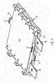
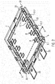
- the Figures 1 and 2 show the essential components of a heat-generating element of the present invention with a PTC element 2, which is connected with its main side surfaces 4 in an electrically conductive manner to a contact sheet 6.
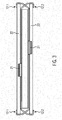
- the contact plate 6 has a plurality of spring tongues 8 formed in one piece on the contact plate 6 by punching and bending. These spring tongues 8 are in the Figures 2 and 3 than from one through that Contact surface 10 formed by punching and bending the contact plate 6 formed by the contact plate 6 can be seen, which are in contact with the PTC element 2 at points or in lines rather than over the entire area.
- Retaining tabs 12 can also be seen, which are formed in one piece on the contact plate 6 by punching and bending and which protrude beyond the contact surfaces 10 of the contact plate 6, which are designed with the dimensions of the main side surface 4.
- the retaining tabs 12 have an in Fig. 4 with reference numeral 14 marked connecting section, which is bent over from the plane of the contact surface 10 of the one contact plate 6.1 to the contact surface 10 of the other contact plate 6.2.
- the connecting section 14 accordingly also extends in the vertical direction of the PTC element 2.
- the connecting section 14 protrudes outwards at an angle of between 35 and 60 ° and to the opposite side.
- the connecting section 14 merges into a holding section 16 which is aligned parallel to the vertical direction of the PTC element 2 and merges into a contact section 18 which is bent inwards at right angles thereto.
- each contact sheet 6 also forms an electrical connection lug 20 cut free by punching and bending, which serves for the plug-in contact of the exemplary embodiment shown and which clearly protrudes beyond the other components of the PTC element 2.
- Positioning stops 21 are each formed by the contact plate 6 between the two connection lugs 20. On the opposite side, there is also a positioning stop 21 per contact sheet, formed by punching and bending the sheet metal material forming the contact sheet.
- the exemplary embodiment also has ceramic insulating plates which form an exemplary embodiment of an insulating layer 22.
- this insulating layer 22 projects beyond the PTC element 2 at the edge.
- the insulating layer 22 accordingly has a larger base area than the contact area 10, the dimensions of which correspond to the main side area 4 of the PTC element 2.
- the insulating layer protrudes beyond this main side surface and the contact surface by at least 0.5 to 2 cm.
- the free ends of the opposing spring tongues 8 formed by the contact section 18 and the holder section 16 form a receptacle 24 for the insulating layer 22.
- the retaining tabs of the contact plates are provided alternately along the longitudinal edges of the PTC element 2.
- the retaining tabs identified by the reference symbol 12.2 belong to the in Figure 1 upper contact surface of the other contact sheet 6.2, where, however, the retaining tabs marked with reference number 12.1 belong to the lower and thus to the one contact sheet 6.1.
- the retaining tabs 12.1 of one contact sheet 6.1 are provided between two retaining tabs 12.2 of the other contact sheet 6.2.
- an insulating and highly thermally conductive compound can be seen, which extends both in the gap between the contact surface 10 and the main side surface 4 and in the gap between a contact surface provided opposite the contact surface 10 and formed by the contact plate 6 28 for the insulating layer 22 and this insulating layer itself.
- this compound fills a gap which is pressed free by the elastic contact of the spring tongues 8 against the main side surface 4.
- the elastic contact of the spring tongues 8 there is a good heat-conducting connection between the PTC element 2 and the contact plate 6.
- the mass 26 can be a hardening, in particular thermosetting plastic mass, for example a two-component silicone, to which a filler made of ceramic and / or metallic powder can be admixed.
- the contact plates 6 are first prepared by punching and bending. Here we not only cut the contact surface 10 free, but also the retaining tabs 12 are formed, essentially in a geometric shape as shown in Figure 4 can be seen.
- the compound 26 is then applied to the main side surface 4 of the PTC element 12 and / or the contact surface 10 of the contact sheet 6.
- the PTC element 2 is placed against the contact surfaces 10 of the two contacts 6.1 and 6.2.
- the insulating layer 22 is then introduced into the receptacle 24.
- the free ends of the retaining tabs 12 are thereby forced outwards.
- the free ends can have a funnel-like configuration in order to be forced outwards as the introduction movement of the insulating layer 22 progresses.
- the free ends of the retaining tabs 12 can also be pushed outward by an external retaining device, so that the receptacle 24 is kept free on the top for inserting the insulating layer 22.
- the compound 26 can be applied to it and / or on the outside of the contact sheet 6.
- the retaining tabs 12 which are elastically flexing back inward, hold the insulating layer 22 in position in the width direction.
- the contact section 18 rests on an edge 30 of the insulating layer 22 which overlaps the PTC element 2 on the edge side.
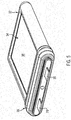
- the Figure 5 shows this with reference to FIG Figures 1-4 described embodiment after the circumferential sheathing with an insulating material which forms a frame identified by reference numeral 32.
- the frame 32 completely surrounds the PTC element 2. Only the connection lugs 20 protrude beyond the frame 32 on the outside.
- the frame 32 forms frame openings 34 opposite one another, in which the predominant part of the outer surface of the insulating layer 22 is exposed as a heat-emitting surface 36.
- the insulating material forming the frame 32 is, for example, a silicone.
- the insulating material forming the frame is usually fluid-tight against the heat-emitting surface 36 of the insulating layer 22, so that the heat-emitting surface 36 can be directly irradiated by a gaseous or liquid fluid to be heated without having to fear that the fluid will reach the current-carrying paths gets inside the frame 32.
- the frame 32 forms, on its side protruding from the terminal lugs 20, sealing lips 38 for sealing insertion into a plug receptacle of a heater housing, as shown in FIG EP 3 334 242 A1 is described.
- connection lugs 20 are at the same height. They are offset from the contact surface 10 by bending inwards. This also results in a stop for the PTC element when it rests against the respective contact surface 10.
Landscapes
- Engineering & Computer Science (AREA)
- Physics & Mathematics (AREA)
- Thermal Sciences (AREA)
- Chemical & Material Sciences (AREA)
- Combustion & Propulsion (AREA)
- Mechanical Engineering (AREA)
- General Engineering & Computer Science (AREA)
- Resistance Heating (AREA)
- Thermistors And Varistors (AREA)
Description
- Die vorliegende Erfindung betrifft ein wärmeerzeugendes Element mit den oberbegrifflichen Merkmalen von Anspruch 1. Ein solches wärmeerzeugendes Element ist aus
EP 0 240 447 A2 bekannt. - Bei diesem Stand der Technik wird eine mit einer Ausnehmung versehene Folie auf ein U-förmig gebogenes Blech aufgelegt. In die Ausnehmung und auf eine Basis des U-förmig gebogenen Blechs wird ein PTC-Element gesetzt, welches auf der der Basis gegenüberliegenden Seite mit einem Kontaktblech versehen wird. Die Lagen der Folie werden auf die dem PTC-Element gegenüberliegende Seite des Kontaktblechs gelegt. Die aufragenden Schenkel der U-förmigen Basis werden umbogen, um das Kontaktblech und das PTC-Element unter Zwischenlage der Isolierung gegen die Basis anzulegen und das wärmeerzeugende Element zu einer Einheit zu fügen.
- Ein ähnlicher Stand der Technik ist aus
JP 2016 186 585 A - Bei dem wärmeerzeugenden Element nach
EP 1 528 838 A2 sind PTC-Elemente in Ausnehmungen eines Rahmens aus einem isolierenden Material aufgenommen, der sich zwischen einem Kontaktstreifen und einem mit Klauen versehenen Gehäuseteil befindet. Auf der dem Kontaktstreifen gegenüberliegenden Seite ist ein weiterer Rahmen mit PTC-Elementen und ein Gehäusekontaktstreifen mit Klauen vorgesehen. Die Klauen der einander gegenüberliegenden Gehäusekontaktstreifen werden gegen den jeweils anderen Gehäusekontaktstreifen angelegt, um das wärmeerzeugende Element zu fügen. Die Gehäusekontaktstreifen sind jeweils aus Blech gebildet. - Solche wärmeerzeugenden Elemente kommen in verschiedenen Bereichen der Technik zum Einsatz. Die vorliegende Erfindung betrifft insbesondere ein wärmeerzeugendes Element für den Einsatz in Kraftfahrzeugen. Hier kommen wärmeerzeugende Elemente der eingangs genannten Art als Zuheizer zum Einsatz, um eine unzureichende Erwärmung von in die Fahrgastzelle eingeleiteter Luft durch den Wärmetauscher, der mit dem Kühlwasser des Motors verbunden ist, zu kompensieren, oder aber in einem Elektrofahrzeug in einer Heizung zur Erwärmung des Innenraumes und zum Entfrosten der Windschutzscheibe. Dies gilt auch für das erfindungsgemäße wärmeerzeugende Element.
- In einem Kraftfahrzeug werden die wärmeerzeugenden Elemente besonderen Bedingungen ausgesetzt. So muss ein erhebliches Temperaturspektrum bei der Auslegung berücksichtigt werden.
- Fahrzeuge können in sehr heißen Regionen oder auch sehr kalten Regionen zum Einsatz kommen. Darüber hinaus werden sämtliche Komponenten in einem Kraftfahrzeug erheblicher Vibration ausgesetzt. Schließlich werden von den Kraftfahrzeugherstellem besondere Anforderungen an die Dauerfestigkeit gestellt, die die Komponenten unter den genannten Bedingungen zu erfüllen haben.
- Des Weiteren sind Anforderungen an die wirtschaftliche Fertigung zu stellen. Wärmeerzeugende Elemente für eine Heizung eines Kraftfahrzeuges müssen sich wirtschaftlich herstellen und leicht handhaben lassen.
- Im Hinblick darauf ist es bekannt, die zuvor erwähnten Komponenten eines wärmeerzeugenden Elementes zu einer baulichen Einheit zu fügen, die im Rahmen der Montage des wärmeerzeugenden Elementes und des Einbaus als Einheit gehandhabt werden kann. So ist beispielsweise aus
EP 2 190 256 A1 ein wärmeerzeugendes Element bekannt, bei dem das PTC-Element mit den beidseitig daran anliegenden Kontaktblechen verklebt wird. Eine solche Lösung eignet sich zwar für die Handhabung der Komponenten. Allerdings kann nicht davon ausgegangen werden, dass die Klebeverbindung derart dauerhaft ist, dass hiermit das PTC-Element und die daran anliegenden Kontaktbleche hinreichend miteinander verbunden sind, so dass über die Lebenszeit der elektrischen Heizvorrichtung des Kraftfahrzeuges eine gute elektrische und wärmeleitende Kontaktierung gewährleistet werden kann. - Andererseits ist es aus der
EP 2 298 582 A1 bzw.EP 1 564 503 A1 der vorliegenden Anmelderin bekannt, die Kontaktbleche und das daran anliegenden PTC-Element zunächst in einem Heizer zu montieren und die elektrische Kontaktierung danach durch Aufbringen einer äußeren Federkraft zu erzeugen, indem in den das wärmeerzeugende Element aufnehmenden Rahmen eine Feder eingelegt wird, die die Elemente der elektrischen Heizvorrichtung vorgespannt gegeneinander anlegt, so dass auch eine gute elektrische Kontaktierung zwischen dem PTC-Element und den Kontaktblechen und eine gute Wärmeableitung der von dem PTC-Element erzeugten Wärme gegeben ist. - Bei Hochvoltanwendungen ist es in der Regel erforderlich, das wärmeerzeugende Element außenseitig mit einer isolierenden Schicht abzudecken, so dass die die Wärme abgebenden Flächen der elektrischen Heizvorrichtung nicht unmittelbar elektrisch leitend an dem Kontaktblech anliegen. Eine solche Lösung ist beispielsweise aus
EP 1 768 457 A1 bekannt. - Der zuvor erwähnte Stand der Technik kann jeweils gattungsgemäß sein. Er lässt noch Wünsche hinsichtlich der dauerhaften und sicheren Kontaktierung zwischen dem Kontaktblech und dem PTC-Element und der leichten Handhabung des wärmeerzeugenden Elementes im Rahmen der Fertigung offen.
- Im Hinblick darauf wird mit der vorliegenden Erfindung ein wärmeerzeugendes Element mit den Merkmalen von Anspruch 1 vorgeschlagen.
- Das erfindungsgemäße wärmeerzeugende Element hat in an sich bekannterWeise zumindest ein PTC-Element und elektrisch leitend daran anliegenden Kontaktbleche zur Bestromung des PTC-Elementes. Die Kontaktbleche liegen an gegenüberliegenden Seitenflächen des PTC-Elementes an. Sie sind voneinander elektrisch isoliert und unterschiedlichen Polaritäten zugeordnet. Das PTC-Element hat dabei üblicherweise eine rechteckige Form, wobei eine Hauptseitenfläche, d. h. diejenige Fläche mit der größten Grundfläche, in der Regel zur Ausleitung der von dem PTC-Element erzeugten Wärme genutzt wird. Hier liegt das Kontaktblech üblicherweise mit seiner Kontaktfläche an dem PTC-Element an. Im Rahmen der Erfindung ist es aber auch denkbar, das Kontaktblech an eine Stirnseitenfläche anzulegen, die die beiden Hauptseitenflächen des PTC-Elements miteinander verbindet und die üblicherweise nicht der Wärmeauskopplung dient. Ebenso gut kann das Kontaktblech sowohl an der Hauptseitenfläche als auch an einer Stirnseitenfläche anliegen.
- Bei der erfindungsgemäßen Ausgestaltung hat zumindest eines der Kontaktbleche Haltelaschen, die üblicherweise an gegenüberliegenden Längsseiten von der Kontaktfläche des Kontaktblechs abragen, um das PTC-Element formschlüssig zu umgreifen. Das Umgreifen erfolgt dabei unter Zwischenlage einer Isolierschicht, so dass die durch den formschlüssigen Umgriff bewirkte mechanische Befestigung des Kontaktbleches an dem PTC-Element nicht gleichzeitig auch eine stromleitende Anlage der Haltelasche an dem PTC-Element ist. Die Haltelaschen liegen an derjenigen Fläche des PTC-Elementes an, welche derjenigen Fläche des PTC-Elementes gegenüberliegt, an der das diese Haltelaschen aufweisenden Kontaktblech zur Bestromung des PTC-Elementes anliegt.
- Bevorzugt erfolgt eine Verspannung des PTC-Elementes gegen die zur elektrischen Kontaktierung ausgebildete Kontaktfläche des Kontaktblechs aufgrund des formschlüssigen Umgriffs durch die Haltelasche. Die Haltelasche hält das PTC-Element unter Vorspannung gegen das Kontaktblech zur Bestromung des PTC-Elementes.
- Das Kontaktblech hat mehrere Haltelaschen, was bedeutet, dass zumindest zwei Haltelaschen einander gegenüberliegen, um einander gegenüberliegende Längsseiten des PTC-Elementes dagegen anzulegen und das PTC-Element gegen das Kontaktblech zu drücken.
- Die Haltelaschen sind üblicherweise einteilig durch Stanzen und Biegen aus einem Blechmaterial herausgearbeitet, so dass die zur Kontaktierung vorgesehene Kontaktfläche des Kontaktbleches und die Haltelaschen an einem einteiligen Blechstück ausgebildet sind. Hierdurch werden die Herstellungskosten vermindert.
- Die das PTC-Element umgreifenden Haltelaschen bewirken aber nicht nur eine Vormontage der Komponenten des wärmeerzeugenden Elementes. Vielmehr ergibt sich aufgrund der dauerhaften elastischen Vorspannung der Kontaktfläche des Kontaktblechs gegen das PTC-Element auch im Betrieb eine vorteilhafte Kontaktierung.
- Die Qualität dieser Kontaktierung und auch der Verbindung zwischen dem Kontaktblech und dem PTC-Element kann dadurch erhöht werden, dass das PTC-Element umfänglich durch die Haltelaschen umgriffen ist. Im Falle eines rechteckigen PTC-Elementes ist an sämtlichen Rändern des PTC-Elementes zumindest eine Haltelasche vorgesehen. Im Falle eines runden PTC-Elementes sind mit einer Teilung von nicht mehr als 30° im Abstand zueinander Haltlaschen vorgesehen. Dadurch wird eine umfängliche Vorspannung der Kontaktfläche des Kontaktbleches gegen das PTC-Element begünstigt.
- Mit Blick auf eine möglichst gute Kontaktierung des PTC-Elements auf beiden Seiten wird gemäß einer bevorzugten Weiterbildung der vorliegenden Erfindung vorgeschlagen, dass jedes der Kontaktbleche mit mehreren Haltelaschen versehen ist und dass die Haltelaschen der jeweiligen Kontaktbleche alternierend das PTC-Element entlang seiner Längskante umgreifen. Dabei umgreifen die Kontaktbleche üblicherweise zumindest an gegenüberliegenden Längskanten das PTC-Element. Auch hier können beide Kontaktbleche das PTC-Element umfänglich umgreifen. Die Haltelaschen sind dabei alternierend vorgesehen, so dass zwei Kontaktlaschen eines ersten Kontaktbleches eine Haltelasche eines zweiten Kontaktbleches zwischen sich aufnehmen. Dadurch wird eine solide Verspannung des PTC-Elementes gegen beide Kontaktflächen der jeweiligen Kontaktbleche bewirkt. Auch wird der Zusammenhalt der vormontierten Komponenten verbessert.
- Gemäß einer bevorzugten Weiterbildung der vorliegenden Erfindung ist die Isolierschicht durch eine Isolierplatte gebildet. Diese Isolierplatte kann beispielsweise eine Keramikplatte aus Aluminiumoxid oder Titannitrid sein. Die Isolierplatte hat eine hinreichende Festigkeit, so dass die durch die elastische Anlage der Haltelaschen aufgebrachte Kraft von der Isolierplatte widergelagert werden kann, ohne dass die Isolierplatte mechanisch geschädigt wird. Als Isolierplatte kommen dabei bevorzugt solche Elemente in Betracht, die eine gute Wärmeleitfähigkeit haben. Dies gilt grundsätzlich für keramische Werkstoffe. Die Isolierplatte erstreckt sich üblicherweise über die gesamte Hauptseitenfläche des PTC-Elementes, d. h. sie deckt die Hauptseitenfläche des PTC-Elementes und die üblicherweise mit gleicher Abmessung vorgesehene und durch das Kontaktblech ausgebildete Kontaktfläche ab. Bevorzugt überragt die Isolierplatte das PTC-Element randseitig. Dies bietet die Möglichkeit, die Haltelaschen mit einer größeren körperlichen Erstreckung vorzusehen, so dass der durch die Haltelasche bereitgestellte Federweg erhöht ist, was sich auf die resultierende Federkraft günstig auswirkt. Auch wird die Luft- bzw. Kriechstrecke durch diese Maßnahme erhöht.
- Die Haltlasche hat dabei üblicherweise ein freies Ende, welches rechtwinklig umbogen ist, so dass ein Anlageabschnitt sich parallel zu Oberfläche der Isolierschicht bzw. Isolierplatte erstreckt und ein Halteabschnitt rechtwinklig von dem Anlageabschnitt abgeht und die Isolierschicht bzw. -platte randseitig einfasst, so dass diese relativ zu dem PTC-Element in Breiten- und/oder Längenrichtung vorpositioniert ist. Die Ausgestaltung stellt danach sicher, dass die über die Haltelaschen fixierte Isolierschicht mittig über dem PTC-Element und der Kontaktfläche angeordnet wird.
- Gemäß einer bevorzugten Weiterbildung der vorliegenden Erfindung hat das Kontaktblech aus dem das Kontaktblech bildenden Blechmaterial freigeschnittene Kontaktlaschen, die zur Ausbildung von an dem PTC-Element anliegenden Kontakten in Richtung auf das PTC-Element umbogen sind. Hierdurch wird zum einen eine elastisch vorgespannte Anlage des Kontaktbleches gegen die zu kontaktierende Oberfläche des PTC-Elementes gebildet. Diese Maßnahme führt zu einer verbesserten elastischen Vorspannung aufgrund des Umgriffs der Haltelaschen. Denn nicht nur die Elastizität der Haltelaschen, sondern auch die Elastizität der Kontaktlaschen bringen elastische Vorspannung auf und verbessern dementsprechend die Kontaktierung des PTC-Elementes einerseits und die Fassung der Komponenten des wärmeerzeugenden Elementes andererseits. Die diskreten Kontakte haben dabei den weiteren Vorteil, dass durch diese eine elektrische Kontaktierung in vorbestimmter Weise bewirkt werden kann. Zur Ausgestaltung der Federzungen und deren Anordnung wird beispielsweise auf die
EP 2 637 475 verwiesen. Die Ausgestaltung und Anordnung der dort beschriebenen Federzungen kann auch für die vorliegende Erfindung zur Anwendung kommen. - Zur möglichst guten Wärmeauskopplung der durch das PTC-Element erzeugten Wärme wird gemäß einer bevorzugen Weiterbildung der vorliegenden Erfindung vorgeschlagen, zwischen dem PTC-Element und dem Kontaktblech eine wärmeleitfähige Masse vorzusehen. Die Masse muss nicht notwendigerweise elektrisch leitend sein, wenn zur definierten Kontaktierung des Kontaktbleches die zuvor erwähnten Federzungen vorgesehen sind. Die wärmeleitfähige Masse füllt den Spalt zwischen der dem PTC-Element zugewandten Kontaktfläche des PTC-Elements und den Kontaktzungen aus, so dass eine gut wärmeleitende Verbindung zwischen dem Kontaktblech und dem PTC-Element gegeben ist. Selbstverständlich kann eine elektrisch und gut wärmeleitfähige Masse verwendet werden. So kann beispielsweise eine mit elektrisch leitfähigen Partikeln gefüllte Kunststoffmasse, beispielsweise Silikon, zur Anwendung kommen. Bevorzugt wird eine wärmeaushärtbare Zweikomponenten-Silikonmasse, die mit besagten Füllstoffanteilen aus Metall oder Keramik gefüllt ist. Die wärmeleitfähige Masse kann sich auch zwischen dem Kontaktblech und der Isolierschicht erstrecken, um auch auf dem Wärmeleitweg hinter dem Kontaktblech eine gute Auskopplung der durch das PTC-Element erzeugten Wärme zu bewirken.
- Insbesondere für Hochvoltanwendung wird gemäß einer bevorzugten Weiterbildung der vorliegenden Erfindung vorgeschlagen, das PTC-Element unter Freilassung einer durch die Isolierschicht gebildeten wärmeabgebenden Fläche vollumfänglich von einem Rahmen aus einem Isolierstoff zu umgeben. Bei dieser Ausgestaltung wird die Außenfläche des wärmeerzeugenden Elementes durch die wärmeabgebenden Flächen der beiden Isolierschichten gebildet, die wärmeleitend das PTC-Element und die Kontaktbleche abdecken und hierzu regelmäßig mit einer der Hauptseitenflächen des PTC-Elementes verbunden sind. Die Isolierschichten werden randseitig von dem Isolierstoff umgeben und regelmäßig darin eingebettet. Dieser Isolierstoff bildet einen Rahmen, der das PTC-Element vollumfänglich umgibt. Der Isolierstoff ist dabei dichtend mit der wärmeabgebenden Fläche verbunden, so dass das wärmeerzeugende Element nach dieser Weiterbildung sich auch zum unmittelbaren Einsatz in einem Flüssigkeitsheizer eignet, in dem die wärmeabgebenden Flächen der Isolierschichten frei liegen. Dieser Rahmen aus Isolierstoff wird üblicherweise ausschließlich von Anschlussfahnen bzw. Kontaktzungen überragt, die zur elektrischen Kontaktierung des PTC-Elements nach Art von männlichen Steckkontaktelementen vorgesehen sind. Zu Details der hier diskutierten Weiterbildung wird auf
EP 3 334 242 A1 verwiesen. - Mit der vorliegenden Erfindung wird ferner ein Verfahren zur Herstellung eines wärmeerzeugenden Elementes angegeben. Bei diesem Verfahren werden zunächst durch Stanzen und Biegen von Blechmaterial Kontaktbleche mit daran angeformten Haltelaschen hergestellt. Die Herstellung erfolgt üblicherweise durch Bearbeitung eines einheitlichen Blechstücks, so dass die Haltelaschen einteilig an dem Kontaktblech ausgebildet werden. Danach werden die Kontaktbleche an gegenüberliegenden Seiten eines PTC-Elementes angelegt, so dass sich die an einer Seite das PTC-Element überragenden Haltelaschen überkreuzen und die das PTC-Element überragenden Haltelaschen des einen Kontaktblechs zwischen ihren freien Enden und dem anderen Kontaktblech eine Aufnahme für eine Isolierschicht ausbilden. In diese Aufnahme wird danach die Isolierschicht unter elastischer Vorspannung der Haltelaschen eingebracht und gegen das andere Kontaktblech angelegt.
- Mit diesem methodischen Vorgehen ist ein einheitliches wärmeerzeugendes Element geschaffen, welches als vormontierte Einheit weiterverarbeitet werden kann. Bevorzugt vor dem Auflegen der Kontaktbleche auf die Oberfläche des PTC-Elementes wird auf besagte Oberfläche eine wärmeleitfähige Masse flüssig aufgegeben, die beim Andrücken der Kontaktbleche gegen das PTC-Element verdrängt wird, so dass die Kontaktbleche elektrisch leitend jedoch ohne verbleibende Lufteinschlüsse gut wärmeleitend gegen das PTC-Element anliegen. Bevorzugt haben die Kontaktbleche Federzungen, die unter elastischer Vorspannung gegen das PTC-Element anliegen und dementsprechend punktuelle Kontakte bewirken. Die wärmeleitfähige Masse kann beim Verpressen des Kontaktblechs gegen das PTC-Element bevorzugt an dem Kontaktblech vorgesehene Durchbrechungen durchsetzten, um in einen Spalt zwischen dem Kontaktblech und der Isolierschicht zu gelangen und auch dort einen etwaigen Freiraum unter Verdrängung von Luft auszufüllen. Alternativ oder ergänzend kann auf dieser dem PTC-Element abgewandten Rückseite des Kontaktbleches zusätzlich wärmeleifähige Masse aufgebracht werden. Dies kann vor dem Aufbringen des Kontaktblechs gegen das PTC-Element und/oder danach erfolgen.
- Die wärmeleifähige Masse ist bevorzugt eine adhäsive Masse, die aushärtet, so dass die gut wärmeleitende Verbindung auch durch die wärmeleitfähige Masse bereitgestellt wird. Aufgrund der Laschen liegen die Isolierschicht und das Kontaktblech unter Federvorspannung gegen das PTC-Element an. Die Komponenten sind zu einer vormontierten Einheit gefügt, so dass diese vormontierte Einheit später beispielsweise zum Umspritzen des Rahmens oder zum Einbau des wärmeerzeugenden Elementes in eine elektrische Heizvorrichtung als Einheit gehandhabt werden können.
- Weitere Einzelheiten und Vorteile der vorliegenden Erfindung entnehmen Sie aus der nachfolgenden Beschreibung eines Ausführungsbeispiels in Verbindung mit der Zeichnung. Darin zeigt:
- Fig. 1
- eine perspektivische Draufsicht auf ein Ausführungsbeispiel vor dem Auflegen der Isolierschicht;
- Fig. 2
- eine perspektivische Draufsicht auf das Ausführungsbeispiel nach
Fig. 1 mit der Isolierschicht; - Fig. 3
- eine Längsschnittansicht entlang der Linie II-II gemäß der Darstellung in
Fig. 2 ; - Fig. 4
- eine Ansicht gemäß
Fig. 3 für einen Randbereich des Ausführungsbeispiels in vergrößerter Darstellung und - Fig. 5
- eine perspektivische Stirnseitenansicht eines wärmeerzeugenden Elementes nach Umspritzen eines isolierenden Rahmens.
- Die
Figuren 1 und2 zeigen die wesentlichen Komponenten eines wärmeerzeugenden Elementes der vorliegenden Erfindung mit einem PTC-Element 2, welches mit seinen Hauptseitenflächen 4 elektrisch leitend mit einem Kontaktblech 6 verbunden ist. Hierzu weist das Kontaktblech 6 mehrere durch Stanzen und Biegen einteilig an dem Kontaktblech 6 ausgebildete Federzungen 8 auf. Diese Federzungen 8 sind in denFiguren 2 und3 als aus einer durch das Kontaktblech 6 gebildeten Kontaktfläche 10 durch Stanzen und Biegen herausgehobene Segmente des Kontaktblechs 6 erkennbar, die eher punktuell bzw. linienförmig als vollflächig an dem PTC-Element 2 anliegen. - In den
Figuren 1 bis 3 sind ferner Haltelaschen 12 erkennbar, die durch Stanzen und Biegen einteilig an dem Kontaktblech 6 ausgeformt sind und die die mit der Abmessung der Hauptseitenfläche 4 ausgebildeten Kontaktflächen 10 des Kontaktblechs 6 überragen. Die Haltelaschen 12 haben einen inFig. 4 mit Bezugszeichen 14 gekennzeichneten Verbindungsabschnitt, der aus der Ebene der Kontaktfläche 10 des einen Kontaktblechs 6.1 zu der Kontaktfläche 10 des anderen Kontaktblechs 6.2 hin umbogen ist. Der Verbindungsabschnitt 14 erstreckt sich dementsprechend auch in Höhenrichtung des PTC-Elementes 2. DerVerbindungsabschnitt 14 ragt mit einem Winkel von zwischen 35 und 60 ° nach außen und zu der gegenüberliegenden Seite hin ab. Der Verbindungsabschnitt 14 geht in einen Halteabschnitt 16 über, der parallel zu der Höhenrichtung des PTC-Elementes 2 ausgerichtet ist und in einen rechtwinklig dazu nach innen abgebogenen Anlageabschnitt 18 übergeht. - Wie aus
Figur 2 zu entnehmen ist, ragen von gegenüberliegenden Rändern der Kontaktfläche 10 jeweils mehrere identische Haltelaschen 12 ab. Jedes Kontaktblech 6 bildet ferner eine durch Stanzen und Biegen freigeschnittene elektrische Anschlussfahne 20 aus, die der Stecckontaktierung des gezeigten Ausführungsbeispiels dient und die übrigen Komponenten des PTC-Elementes 2 deutlich überragt. Zwischen den beiden Anschlussfahnen 20 sind jeweils durch das Kontaktblech 6 Positionieranschläge 21 gebildet. Auch auf der gegenüberliegenden Seite befindet sich pro Kontaktblech je ein durch Stanzen und Biegen des das Kontaktblech bildenden Blechmaterials gebildeter Positionieranschlag 21. So befindet sich die Isolierschicht 22 allseits formschlüssig eingeschlossen über der durch das zugehörige Kontaktblech 6 gebildeten Kontaktfläche 10. - Das Ausführungsbeispiel hat ferner keramische Isolierplatten, die ein Ausführungsbeispiel einer Isolierschicht 22 ausbildet. Wie den
Figuren 2 bis 4 zu entnehmen ist, überragt diese Isolierschicht 22 das PTC-Element 2 randseitig. Die Isolierschicht 22 hat dementsprechend eine größere Grundfläche als die Kontaktfläche 10, deren Abmessung der Hauptseitenfläche 4 des PTC-Elementes 2 entspricht. Die Isolierschicht überragt diese Hauptseitenfläche und die Kontaktfläche um mindestens 0,5 bis 2 cm. - Die durch den Anlageabschnitt 18 und den Halterabschnitt 16 gebildeten freien Enden der einander gegenüberliegenden Federzungen 8 bilden eine Aufnahme 24 für die Isolierschicht 22 aus.
- Wie insbesondere
Figur 2 vermittelt, sind die Haltelaschen der Kontaktbleche jeweils alternierend entlang der Längskanten des PTC-Elementes 2 vorgesehen. So gehören die mit Bezugszeichen 12.2 gekennzeichneten Haltelaschen zu der inFigur 1 oberen Kontaktfläche des anderen Kontaktbleches 6.2, wo hingegen die mit Bezugszeichen 12.1 gekennzeichneten Haltelaschen zu dem unteren und damit dem einen Kontaktblech 6.1 gehören. So sind die Haltelaschen 12.1 des einen Kontaktblechs 6.1 zwischen jeweils zwei Haltelaschen 12.2 des anderen Kontaktblechs 6.2 vorgesehen. - Der vergrößerten Darstellung gemäß
Figur 4 ist ferner eine isolierende und mit Bezugszeichen 26 gekennzeichnete gut wärmeleitfähige Masse zu entnehmen, die sich sowohl in dem Spalt zwischen der Kontaktfläche 10 und der Hauptseitenfläche 4 erstreckt, wie auch in dem Spalt zwischen einer der Kontaktfläche 10 gegenüberliegend vorgesehenen und durch das Kontaktblech 6 gebildeten Anlagefläche 28 für die Isolierschicht 22 und dieser Isolierschicht selbst. - Zwischen der Hauptseitenfläche 4 und der Kontaktfläche 10 füllt diese Masse 26 einen Spalt aus, der durch die elastische Anlage der Federzungen 8 gegen die Hauptseitenfläche 4 freigedrückt wird. So ergibt sich trotz der elastischen Anlage der Federzungen 8 eine gut wärmeleitende Verbindung zwischen dem PTC-Element 2 und dem Kontaktblech 6. Entsprechendes gilt aufgrund der auf der gegenüberliegenden Seite vorgesehenen isolierenden Masse für die wärmeleitende Verbindung zwischen dem Kontaktblech 6 und der Isolierschicht 22.
- Die Masse 26 kann eine aushärtende, insbesondere warmaushärtende Kunststoffmasse sein, beispielsweise ein Zwei-Komponenten-Silikon, dem ein Füllstoff aus Keramik und/oder metallischem Pulver beigemischt sein kann.
- Wie insbesondere
Figur 4 zu entnehmen ist, ergibt sich folgende Abfolge der Elemente des gezeigten Ausführungsbeispiels in Querschnittsrichtung von oben nach unten: Außen befinden sich zunächst die Anlageabschnitte 18. In Querschnittsrichtung folgt die Isolierschicht 22. Eingebettete von der Masse 26 folgt das Kontaktblech 6, soweit dieses die Kontaktfläche 10 ausformt. In Querschnittsrichtung folgt danach das PTC-Element 2 und außenseitig hierzu parallel die Verbindungsabschnitte 14 der beiden Kontaktbleche 6. Im Anschluss an des PTC-Element 2 ist der zuvor beschriebene geschichtete Aufbau spiegelsymmetrisch zu der Mittellängsachse der Querschnittsgestaltung vorgesehen. - Zur Herstellung des gezeigten Ausführungsbeispiels werden zunächst die Kontaktbleche 6 durch Stanzen und Biegen vorbereitet. Hierbei wir nicht nur die Kontaktfläche 10 freigeschnitten, sondern es werden auch die Haltelaschen 12 ausgebildet, und zwar im Wesentlichen in einer geometrischen Ausformung, wie sie in
Figur 4 zu erkennen ist. Danach wird auf die Hauptseitenfläche 4 des PTC-Elementes 12 und/oder die Kontaktfläche 10 des Kontaktblechs 6 die Masse 26 aufgebracht. Das PTC-Element 2 wird gegen die Kontaktflächen 10 der beiden Kontakte 6.1 und 6.2 angelegt. Danach wird die Isolierschicht 22 in die Aufnahme 24 eingebracht. Dabei werden die freien Enden der Haltelaschen 12 nach außen gedrängt. Die freien Enden können eine trichterartige Ausgestaltung aufweisen, um mit fortschreitender Einbringbewegung der Isolierschicht 22 nach außen gedrängt zu werden. Alternativ können die freien Enden der Haltelaschen 12 auch durch eine äußere Haltevorrichtung nach außen gedrängt werden, sodass die Aufnahme 24 für das Einlegen der Isolierschicht 22 oberseitig freigehalten wird. - Vor dem Auflegen der Isolierschicht 22 kann auf diese und/oder außenseitig auf das Kontaktblech 6 die Masse 26 aufgebracht werden. Nach dem Einbringen der Isolierschicht 22 in die Aufnahme 24 halten die elastisch nach innen zurückflexenden Haltelaschen 12 die Isolierschicht 22 in Breitenrichtung in Position. Darüber hinaus ergibt sich eine elastische Vorspannung auf Grund der Anlage der Anlageabschnitte 18 gegen die Außenfläche der Isolierschicht 22, sodass diese zusammen mit der Kontaktfläche 10 unter elastischer Vorspannung gegen die Hauptseitenfläche 4 des PTC-Elementes 2 angelegt wird. Wie
Figur 4 zu entnehmen ist, liegt der Anlageabschnitt 18 an einem Rand 30 der Isolierschicht 22 an, der das PTC-Element 2 randseitig übergreift. - Die
Figur 5 zeigt das unter Bezugnahme auf dieFiguren 1-4 beschriebene Ausführungsbeispiel nach dem umfänglichen Umhüllen mit einem Isolierstoff, der einen mit Bezugszeichen 32 gekennzeichneten Rahmen ausbildet. Der Rahmen 32 umgibt das PTC-Element 2 voll umfänglich. Lediglich die Anschlussfahnen 20 überragen den Rahmen 32 außenseitig. Der Rahmen 32 bildet einander gegenüberüberliegende Rahmenöffnungen 34 aus, in denen der überwiegende Teil der Außenfläche der Isolierschicht 22 als wärmeabgebende Fläche 36 freiliegt. Der den Rahmen 32 ausbildende Isolierstoff ist beispielsweise ein Silikon. Der den Rahmen ausbildende Isolierstoff liegt üblicherweise fluiddicht gegen die wärmeabgebende Fläche 36 der Isolierschicht 22 an, sodass die wärmeabgebende Fläche 36 unmittelbar von einem zu erwärmenden gasförmigen oder flüssigen Fluid angestrahlt werden kann, ohne dass zu befürchten ist, dass das Fluid bis zu den stromführenden Bahnen innerhalb des Rahmens 32 gelangt. Der Rahmen 32 bildet an seiner von den Anschlussfahnen 20 überragten Seite Dichtlippen 38 zum dichtenden Einsetzen in eine Steckeraufnahme eines Heizergehäuses aus, wie dies inEP 3 334 242 A1 beschrieben ist. - Wie die
Figuren 1 und5 verdeutlichen befinden sich die Anschlussfahnen 20 auf gleicher Höhe. Sie sind durch Biegen nach innen gegenüber der Kontaktfläche 10 versetzt. Dadurch ergibt sich auch ein Anschlag für das PTC-Element bei Anlage gegen die jeweilige Kontaktfläche 10. -
- 2
- PTC-Element
- 4
- Hauptseitenfläche
- 6
- Kontaktblech
- 8
- Federzunge
- 10
- Kontaktfläche
- 12
- Haltelasche
- 14
- Verbindungsabschnitt
- 16
- Halteabschnitt
- 18
- Anlageabschnitt
- 20
- Anschlussfahne
- 21
- Positionieranschlag
- 22
- Isolierschicht
- 24
- Aufnahme
- 26
- Masse
- 28
- Anlagefläche
- 30
- Rand
- 32
- Rahmen
- 34
- Rahmenöffnung
- 36
- wärmeabgebende Fläche
- 38
- Dichtlippe
Claims (9)
- Wärmeerzeugendes Element mit einem PTC-Element (2), mit elektrisch leitend an Seitenflächen (4) des PTC-Elementes (2) anliegenden Kontaktblechen (6.1; 6.2), die zur Bestromung des PTC-Elements (2) mit unterschiedlicher Polarität vorgesehen sind, und mit einer Isolierschicht (22), die an einer dem PTC-Element (2) abgewandten Hauptseitenfläche eines der Kontaktbleche (6.1; 6.2) anliegt, dadurch gekennzeichnet, dass die Isolierschicht durch eine Isolierplatte (22) gebildet ist und dass zumindest eines der Kontaktbleche (6.1; 6.2) mit Haltelaschen (12) versehen ist, die auf einer gegenüberliegenden Seitenfläche (4) des PTC-Elementes (2), an der das andere der Kontaktbleche (6.2; 6.1) elektrisch leitend anliegt, unter Zwischenlage der Isolierplatte (22) gegen das PTC-Element (2) anliegen und das PTC-Element (2) und die Isolierplatte (22) formschlüssig umgreifen, wobei von den Haltelaschen (12) formschlüssig umgriffene Ränder (30) der Isolierplatte (22) das PTC-Element (2) randseitig überragen.
- Wärmeerzeugendes Wärmeelement nach Anspruch 1, dadurch gekennzeichnet, dass das PTC-Elementes (2) unter Vorspannung zwischen den Haltlaschen (12) des Kontaktblechs (6) und einer elektrisch leitend an der zugeordneten Seitenfläche (4) des PTC-Elementes (2) anliegenden Kontaktfläche (10) des Kontaktblechs (6) gehalten ist.
- Wärmeerzeugendes Wärmeelement nach Anspruch 1 oder 2, dadurch gekennzeichnet, dass PTC-Element (2) umfänglich durch Haltelaschen (12) umgriffen ist.
- Wärmeerzeugendes Element nach einem der vorherigen Ansprüche, dadurch gekennzeichnet, dass jedes der Kontaktbleche (6) mit mehreren Haltelaschen (12) versehen ist und dass die Haltelaschen (12) der jeweiligen Kontaktbleche (6.1; 6.2) alternierend das PTC-Element (2) entlang seiner Längskante umgreifen.
- Wärmeerzeugendes Element nach einem der vorherigen Ansprüche, dadurch gekennzeichnet, dass das Kontaktblech (6) aus dem das Kontaktblech bildenden Blechmaterial freigeschnittene Federzungen (8) aufweist, die zur Ausbildung von an dem PTC-Element (2) anliegenden Kontakten in Richtung auf das PTC-Element (2) umbogen sind.
- Wärmeerzeugendes Element nach einem der vorherigen Ansprüche, dadurch gekennzeichnet, dass zwischen dem PTC-Element (2) und dem Kontaktblech (6) und/oder der Isolierschicht (22) eine wärmeleitfähige Masse (26) vorgesehen ist.
- Wärmeerzeugendes Element nach einem der vorherigen Ansprüche, dadurch gekennzeichnet, dass das PTC-Element (2) unter Freilassung einer durch die Isolierschicht (22) gebildeten wärmeabführenden Fläche (36) vollumfänglich von einem Rahmen (32) aus einem Isolierstoff umgeben ist.
- Wärmeerzeugendes Element nach einem der vorherigen Ansprüche, dadurch gekennzeichnet, dass das Kontaktblech (6) eine durch Stanzen und Biegen freigeschnittene elektrische Anschlussfahne (20) ausbildet.
- Verfahren zur Herstellung eines wärmeerzeugenden Elementes nach Anspruch 1, bei dem durch Stanzen und Biegen von Blechmaterial Kontaktbleche (6) mit Haltelaschen (12) hergestellt werden, die Kontaktbleche (6) an gegenüberliegenden Seiten eines PTC-Element (2) angelegt werden, sodass sich die an einer Seite das PTC-Element (2) überragenden Haltelaschen (12) überkreuzen und die das PTC-Element (2) überragenden Haltelaschen (12.1) des einen Kontaktblechs (6.1) zwischen ihren freien Enden und dem anderen Kontaktblech (6.2) eine Aufnahme (24) für eine Isolationsschicht (22) ausbilden und die Isolierschicht unter elastischer Vorspannung der Haltelaschen (12) in die Aufnahme (24) eingebracht und gegen das andere Kontaktblech (6.2) angelegt wird.
Applications Claiming Priority (1)
| Application Number | Priority Date | Filing Date | Title |
|---|---|---|---|
| DE102018212012.9A DE102018212012A1 (de) | 2018-07-18 | 2018-07-18 | Wärmeerzeugendes Element und Verfahren zu dessen Herstellung |
Publications (2)
| Publication Number | Publication Date |
|---|---|
| EP3598847A1 EP3598847A1 (de) | 2020-01-22 |
| EP3598847B1 true EP3598847B1 (de) | 2021-09-29 |
Family
ID=67314659
Family Applications (1)
| Application Number | Title | Priority Date | Filing Date |
|---|---|---|---|
| EP19186522.9A Active EP3598847B1 (de) | 2018-07-18 | 2019-07-16 | Wärmeerzeugendes element und verfahren zu dessen herstellung |
Country Status (3)
| Country | Link |
|---|---|
| EP (1) | EP3598847B1 (de) |
| CN (1) | CN110740527B (de) |
| DE (1) | DE102018212012A1 (de) |
Families Citing this family (3)
| Publication number | Priority date | Publication date | Assignee | Title |
|---|---|---|---|---|
| DE102018212012A1 (de) * | 2018-07-18 | 2020-01-23 | Eberspächer Catem Gmbh & Co. Kg | Wärmeerzeugendes Element und Verfahren zu dessen Herstellung |
| DE102018122436B4 (de) | 2018-09-13 | 2024-08-22 | Eichenauer Heizelemente Gmbh & Co. Kg | Heizerbaugruppe und Heizergehäuse mit einer solchen Heizerbaugruppe |
| GB2618837A (en) * | 2022-05-19 | 2023-11-22 | Finar Module Sagl | enclosure for a power resistor assembly |
Family Cites Families (17)
| Publication number | Priority date | Publication date | Assignee | Title |
|---|---|---|---|---|
| US2606986A (en) * | 1951-07-14 | 1952-08-12 | Barber Colman Co | Resistance unit |
| DE3042420A1 (de) * | 1980-11-11 | 1982-06-24 | Fritz Eichenauer GmbH & Co KG, 6744 Kandel | Elektrischer heizkoerper mit ein oder mehreren flachen, quaderfoermigen heizelementen |
| US4698614A (en) * | 1986-04-04 | 1987-10-06 | Emerson Electric Co. | PTC thermal protector |
| DE3677603D1 (de) * | 1986-10-01 | 1991-03-28 | David & Baader Dbk Spezfab | Kaltleiter-ptc-heizkoerper. |
| EP0333906B1 (de) * | 1988-03-25 | 1993-10-20 | David & Baader DBK Spezialfabrik elektrischer Apparate und Heizwiderstände GmbH | Kaltleiter-PTC-Heizkörper |
| JP2532502Y2 (ja) * | 1991-02-20 | 1997-04-16 | 株式会社村田製作所 | 発熱ユニット |
| GB0325574D0 (en) * | 2003-11-03 | 2003-12-03 | Delphi Tech Inc | Electrical heater |
| ES2295713T3 (es) | 2004-02-10 | 2008-04-16 | CATEM GMBH & CO. KG | Dispositivo calefactor electrico de poca altura. |
| DE502005004134D1 (de) | 2005-09-23 | 2008-06-26 | Catem Gmbh & Co Kg | Wärmeerzeugendes Element einer Heizvorrichtung |
| US7985472B2 (en) * | 2007-06-22 | 2011-07-26 | Exopack-Technology, Llc | Low-gloss dry-erase coating formulation |
| EP2190258A1 (de) | 2008-11-20 | 2010-05-26 | Behr France Rouffach SAS | Wärmeübertrager |
| EP2276321B1 (de) * | 2009-07-17 | 2017-04-05 | Mahle Behr France Rouffach S.A.S | Wärmeübertrager |
| EP2298582B1 (de) | 2009-09-22 | 2011-11-16 | Eberspächer catem GmbH & Co. KG | Elektrische Heizvorrichtung und Verfahren zu deren Herstellung |
| EP2637475B9 (de) | 2012-03-08 | 2017-01-25 | Eberspächer catem GmbH & Co. KG | Wärme erzeugendes Element |
| JP6590501B2 (ja) * | 2015-03-27 | 2019-10-16 | Fdk株式会社 | 外付けptc素子および筒形電池 |
| DE102016224296A1 (de) | 2016-12-06 | 2018-06-07 | Eberspächer Catem Gmbh & Co. Kg | Elektrische heizvorrichtung |
| DE102018212012A1 (de) * | 2018-07-18 | 2020-01-23 | Eberspächer Catem Gmbh & Co. Kg | Wärmeerzeugendes Element und Verfahren zu dessen Herstellung |
-
2018
- 2018-07-18 DE DE102018212012.9A patent/DE102018212012A1/de not_active Withdrawn
-
2019
- 2019-07-16 EP EP19186522.9A patent/EP3598847B1/de active Active
- 2019-07-18 CN CN201910653384.XA patent/CN110740527B/zh active Active
Also Published As
| Publication number | Publication date |
|---|---|
| EP3598847A1 (de) | 2020-01-22 |
| DE102018212012A1 (de) | 2020-01-23 |
| CN110740527A (zh) | 2020-01-31 |
| CN110740527B (zh) | 2022-08-30 |
Similar Documents
| Publication | Publication Date | Title |
|---|---|---|
| EP3334244B1 (de) | Elektrische heizvorrichtung und ptc-heizelement für eine solche | |
| EP3863373B1 (de) | Elektrische heizvorrichtung und verfahren zu deren herstellung | |
| EP3493650B1 (de) | Elektrische heizvorrichtung | |
| EP2608632B1 (de) | Elektrische Heizvorrichtung und Rahmen hierfür | |
| EP2337425B1 (de) | Elektrische Heizvorrichtung und wärmeerzeugendes Element einer elektrischen Heizvorrichtung | |
| EP2608633B1 (de) | Wärme erzeugendes Element | |
| EP3101998A1 (de) | Ptc-heizelement sowie elektrische heizvorrichtung umfassend ein solches ptc-heizelement und verfahren zum herstellen einer elektrischen heizvorrichtung | |
| EP1916875A2 (de) | Wärmeerzeugendes Element einer Heizvorrichtung | |
| EP3598847B1 (de) | Wärmeerzeugendes element und verfahren zu dessen herstellung | |
| EP3101999A1 (de) | Ptc-heizelement und elektrische heizvorrichtung für ein kraftfahrzeug umfassend ein solches ptc-heizelement | |
| EP2607808A1 (de) | Wärme erzeugendes Element | |
| DE102019205848A1 (de) | PTC-Heizelement und elektrische Heizvorrichtung mit einem solchen PTC-Heizelement und Verfahren zur Herstellung eines PTC-Heizelementes | |
| EP3101365A1 (de) | Verfahren zur herstellung einer elektrischen heizvorrichtung | |
| DE102019204665A1 (de) | PTC-Heizelement und eine elektrische Heizvorrichtung | |
| EP2884817A1 (de) | Elektrische Heizvorrichtung und Verfahren zu deren Herstellung | |
| EP2884197B1 (de) | Elektrische Heizvorrichtung und Verfahren zu deren Herstellung | |
| DE102019204472B4 (de) | Wärmeerzeugendes Element und elektrische Heizvorrichtung enthaltend ein solches | |
| EP3405001B1 (de) | Verfahren zum herstellen eines ptc-heizelementes | |
| EP3557155A1 (de) | Elektrische heizvorrichtung | |
| EP2957840A1 (de) | Elektrische Heizvorrichtung | |
| DE102018221654B4 (de) | PTC-Heizelement und Verfahren zu dessen Herstellung | |
| DE102020113402A1 (de) | Elektrische Heizvorrichtung | |
| DE102020117366A1 (de) | Elektrische Steuervorrichtung, insbesondere für eine elektrische Heizvorrichtung | |
| DE102020202195A1 (de) | Elektrische Heizeinrichtung | |
| DE102019217453A1 (de) | PTC-Heizzelle |
Legal Events
| Date | Code | Title | Description |
|---|---|---|---|
| PUAI | Public reference made under article 153(3) epc to a published international application that has entered the european phase |
Free format text: ORIGINAL CODE: 0009012 |
|
| STAA | Information on the status of an ep patent application or granted ep patent |
Free format text: STATUS: THE APPLICATION HAS BEEN PUBLISHED |
|
| AK | Designated contracting states |
Kind code of ref document: A1 Designated state(s): AL AT BE BG CH CY CZ DE DK EE ES FI FR GB GR HR HU IE IS IT LI LT LU LV MC MK MT NL NO PL PT RO RS SE SI SK SM TR |
|
| AX | Request for extension of the european patent |
Extension state: BA ME |
|
| STAA | Information on the status of an ep patent application or granted ep patent |
Free format text: STATUS: REQUEST FOR EXAMINATION WAS MADE |
|
| 17P | Request for examination filed |
Effective date: 20200327 |
|
| RBV | Designated contracting states (corrected) |
Designated state(s): AL AT BE BG CH CY CZ DE DK EE ES FI FR GB GR HR HU IE IS IT LI LT LU LV MC MK MT NL NO PL PT RO RS SE SI SK SM TR |
|
| GRAP | Despatch of communication of intention to grant a patent |
Free format text: ORIGINAL CODE: EPIDOSNIGR1 |
|
| RIC1 | Information provided on ipc code assigned before grant |
Ipc: H05B 3/50 20060101AFI20210324BHEP Ipc: F24H 3/04 20060101ALI20210324BHEP Ipc: F24H 9/18 20060101ALI20210324BHEP Ipc: B60H 1/22 20060101ALI20210324BHEP |
|
| STAA | Information on the status of an ep patent application or granted ep patent |
Free format text: STATUS: GRANT OF PATENT IS INTENDED |
|
| INTG | Intention to grant announced |
Effective date: 20210429 |
|
| GRAS | Grant fee paid |
Free format text: ORIGINAL CODE: EPIDOSNIGR3 |
|
| GRAA | (expected) grant |
Free format text: ORIGINAL CODE: 0009210 |
|
| STAA | Information on the status of an ep patent application or granted ep patent |
Free format text: STATUS: THE PATENT HAS BEEN GRANTED |
|
| AK | Designated contracting states |
Kind code of ref document: B1 Designated state(s): AL AT BE BG CH CY CZ DE DK EE ES FI FR GB GR HR HU IE IS IT LI LT LU LV MC MK MT NL NO PL PT RO RS SE SI SK SM TR |
|
| REG | Reference to a national code |
Ref country code: GB Ref legal event code: FG4D Free format text: NOT ENGLISH |
|
| REG | Reference to a national code |
Ref country code: DE Ref legal event code: R096 Ref document number: 502019002377 Country of ref document: DE |
|
| REG | Reference to a national code |
Ref country code: CH Ref legal event code: EP Ref country code: AT Ref legal event code: REF Ref document number: 1435380 Country of ref document: AT Kind code of ref document: T Effective date: 20211015 |
|
| REG | Reference to a national code |
Ref country code: IE Ref legal event code: FG4D Free format text: LANGUAGE OF EP DOCUMENT: GERMAN |
|
| REG | Reference to a national code |
Ref country code: LT Ref legal event code: MG9D |
|
| PG25 | Lapsed in a contracting state [announced via postgrant information from national office to epo] |
Ref country code: LT Free format text: LAPSE BECAUSE OF FAILURE TO SUBMIT A TRANSLATION OF THE DESCRIPTION OR TO PAY THE FEE WITHIN THE PRESCRIBED TIME-LIMIT Effective date: 20210929 Ref country code: BG Free format text: LAPSE BECAUSE OF FAILURE TO SUBMIT A TRANSLATION OF THE DESCRIPTION OR TO PAY THE FEE WITHIN THE PRESCRIBED TIME-LIMIT Effective date: 20211229 Ref country code: HR Free format text: LAPSE BECAUSE OF FAILURE TO SUBMIT A TRANSLATION OF THE DESCRIPTION OR TO PAY THE FEE WITHIN THE PRESCRIBED TIME-LIMIT Effective date: 20210929 Ref country code: NO Free format text: LAPSE BECAUSE OF FAILURE TO SUBMIT A TRANSLATION OF THE DESCRIPTION OR TO PAY THE FEE WITHIN THE PRESCRIBED TIME-LIMIT Effective date: 20211229 Ref country code: SE Free format text: LAPSE BECAUSE OF FAILURE TO SUBMIT A TRANSLATION OF THE DESCRIPTION OR TO PAY THE FEE WITHIN THE PRESCRIBED TIME-LIMIT Effective date: 20210929 Ref country code: RS Free format text: LAPSE BECAUSE OF FAILURE TO SUBMIT A TRANSLATION OF THE DESCRIPTION OR TO PAY THE FEE WITHIN THE PRESCRIBED TIME-LIMIT Effective date: 20210929 Ref country code: FI Free format text: LAPSE BECAUSE OF FAILURE TO SUBMIT A TRANSLATION OF THE DESCRIPTION OR TO PAY THE FEE WITHIN THE PRESCRIBED TIME-LIMIT Effective date: 20210929 |
|
| REG | Reference to a national code |
Ref country code: NL Ref legal event code: MP Effective date: 20210929 |
|
| PG25 | Lapsed in a contracting state [announced via postgrant information from national office to epo] |
Ref country code: LV Free format text: LAPSE BECAUSE OF FAILURE TO SUBMIT A TRANSLATION OF THE DESCRIPTION OR TO PAY THE FEE WITHIN THE PRESCRIBED TIME-LIMIT Effective date: 20210929 Ref country code: GR Free format text: LAPSE BECAUSE OF FAILURE TO SUBMIT A TRANSLATION OF THE DESCRIPTION OR TO PAY THE FEE WITHIN THE PRESCRIBED TIME-LIMIT Effective date: 20211230 |
|
| PG25 | Lapsed in a contracting state [announced via postgrant information from national office to epo] |
Ref country code: IS Free format text: LAPSE BECAUSE OF FAILURE TO SUBMIT A TRANSLATION OF THE DESCRIPTION OR TO PAY THE FEE WITHIN THE PRESCRIBED TIME-LIMIT Effective date: 20220129 Ref country code: SK Free format text: LAPSE BECAUSE OF FAILURE TO SUBMIT A TRANSLATION OF THE DESCRIPTION OR TO PAY THE FEE WITHIN THE PRESCRIBED TIME-LIMIT Effective date: 20210929 Ref country code: RO Free format text: LAPSE BECAUSE OF FAILURE TO SUBMIT A TRANSLATION OF THE DESCRIPTION OR TO PAY THE FEE WITHIN THE PRESCRIBED TIME-LIMIT Effective date: 20210929 Ref country code: PT Free format text: LAPSE BECAUSE OF FAILURE TO SUBMIT A TRANSLATION OF THE DESCRIPTION OR TO PAY THE FEE WITHIN THE PRESCRIBED TIME-LIMIT Effective date: 20220131 Ref country code: PL Free format text: LAPSE BECAUSE OF FAILURE TO SUBMIT A TRANSLATION OF THE DESCRIPTION OR TO PAY THE FEE WITHIN THE PRESCRIBED TIME-LIMIT Effective date: 20210929 Ref country code: NL Free format text: LAPSE BECAUSE OF FAILURE TO SUBMIT A TRANSLATION OF THE DESCRIPTION OR TO PAY THE FEE WITHIN THE PRESCRIBED TIME-LIMIT Effective date: 20210929 Ref country code: ES Free format text: LAPSE BECAUSE OF FAILURE TO SUBMIT A TRANSLATION OF THE DESCRIPTION OR TO PAY THE FEE WITHIN THE PRESCRIBED TIME-LIMIT Effective date: 20210929 Ref country code: EE Free format text: LAPSE BECAUSE OF FAILURE TO SUBMIT A TRANSLATION OF THE DESCRIPTION OR TO PAY THE FEE WITHIN THE PRESCRIBED TIME-LIMIT Effective date: 20210929 Ref country code: CZ Free format text: LAPSE BECAUSE OF FAILURE TO SUBMIT A TRANSLATION OF THE DESCRIPTION OR TO PAY THE FEE WITHIN THE PRESCRIBED TIME-LIMIT Effective date: 20210929 Ref country code: AL Free format text: LAPSE BECAUSE OF FAILURE TO SUBMIT A TRANSLATION OF THE DESCRIPTION OR TO PAY THE FEE WITHIN THE PRESCRIBED TIME-LIMIT Effective date: 20210929 |
|
| REG | Reference to a national code |
Ref country code: DE Ref legal event code: R097 Ref document number: 502019002377 Country of ref document: DE |
|
| PG25 | Lapsed in a contracting state [announced via postgrant information from national office to epo] |
Ref country code: DK Free format text: LAPSE BECAUSE OF FAILURE TO SUBMIT A TRANSLATION OF THE DESCRIPTION OR TO PAY THE FEE WITHIN THE PRESCRIBED TIME-LIMIT Effective date: 20210929 |
|
| PLBE | No opposition filed within time limit |
Free format text: ORIGINAL CODE: 0009261 |
|
| STAA | Information on the status of an ep patent application or granted ep patent |
Free format text: STATUS: NO OPPOSITION FILED WITHIN TIME LIMIT |
|
| 26N | No opposition filed |
Effective date: 20220630 |
|
| PG25 | Lapsed in a contracting state [announced via postgrant information from national office to epo] |
Ref country code: SI Free format text: LAPSE BECAUSE OF FAILURE TO SUBMIT A TRANSLATION OF THE DESCRIPTION OR TO PAY THE FEE WITHIN THE PRESCRIBED TIME-LIMIT Effective date: 20210929 |
|
| PG25 | Lapsed in a contracting state [announced via postgrant information from national office to epo] |
Ref country code: MC Free format text: LAPSE BECAUSE OF FAILURE TO SUBMIT A TRANSLATION OF THE DESCRIPTION OR TO PAY THE FEE WITHIN THE PRESCRIBED TIME-LIMIT Effective date: 20210929 |
|
| REG | Reference to a national code |
Ref country code: CH Ref legal event code: PL |
|
| REG | Reference to a national code |
Ref country code: BE Ref legal event code: MM Effective date: 20220731 |
|
| PG25 | Lapsed in a contracting state [announced via postgrant information from national office to epo] |
Ref country code: LU Free format text: LAPSE BECAUSE OF NON-PAYMENT OF DUE FEES Effective date: 20220716 Ref country code: LI Free format text: LAPSE BECAUSE OF NON-PAYMENT OF DUE FEES Effective date: 20220731 Ref country code: CH Free format text: LAPSE BECAUSE OF NON-PAYMENT OF DUE FEES Effective date: 20220731 |
|
| PG25 | Lapsed in a contracting state [announced via postgrant information from national office to epo] |
Ref country code: BE Free format text: LAPSE BECAUSE OF NON-PAYMENT OF DUE FEES Effective date: 20220731 |
|
| PG25 | Lapsed in a contracting state [announced via postgrant information from national office to epo] |
Ref country code: IE Free format text: LAPSE BECAUSE OF NON-PAYMENT OF DUE FEES Effective date: 20220716 |
|
| PGFP | Annual fee paid to national office [announced via postgrant information from national office to epo] |
Ref country code: IT Payment date: 20230731 Year of fee payment: 5 |
|
| PGFP | Annual fee paid to national office [announced via postgrant information from national office to epo] |
Ref country code: FR Payment date: 20230724 Year of fee payment: 5 |
|
| GBPC | Gb: european patent ceased through non-payment of renewal fee |
Effective date: 20230716 |
|
| PG25 | Lapsed in a contracting state [announced via postgrant information from national office to epo] |
Ref country code: HU Free format text: LAPSE BECAUSE OF FAILURE TO SUBMIT A TRANSLATION OF THE DESCRIPTION OR TO PAY THE FEE WITHIN THE PRESCRIBED TIME-LIMIT; INVALID AB INITIO Effective date: 20190716 |
|
| PG25 | Lapsed in a contracting state [announced via postgrant information from national office to epo] |
Ref country code: SM Free format text: LAPSE BECAUSE OF FAILURE TO SUBMIT A TRANSLATION OF THE DESCRIPTION OR TO PAY THE FEE WITHIN THE PRESCRIBED TIME-LIMIT Effective date: 20210929 Ref country code: MK Free format text: LAPSE BECAUSE OF FAILURE TO SUBMIT A TRANSLATION OF THE DESCRIPTION OR TO PAY THE FEE WITHIN THE PRESCRIBED TIME-LIMIT Effective date: 20210929 Ref country code: CY Free format text: LAPSE BECAUSE OF FAILURE TO SUBMIT A TRANSLATION OF THE DESCRIPTION OR TO PAY THE FEE WITHIN THE PRESCRIBED TIME-LIMIT Effective date: 20210929 Ref country code: GB Free format text: LAPSE BECAUSE OF NON-PAYMENT OF DUE FEES Effective date: 20230716 |
|
| PG25 | Lapsed in a contracting state [announced via postgrant information from national office to epo] |
Ref country code: TR Free format text: LAPSE BECAUSE OF FAILURE TO SUBMIT A TRANSLATION OF THE DESCRIPTION OR TO PAY THE FEE WITHIN THE PRESCRIBED TIME-LIMIT Effective date: 20210929 |
|
| PG25 | Lapsed in a contracting state [announced via postgrant information from national office to epo] |
Ref country code: MT Free format text: LAPSE BECAUSE OF FAILURE TO SUBMIT A TRANSLATION OF THE DESCRIPTION OR TO PAY THE FEE WITHIN THE PRESCRIBED TIME-LIMIT Effective date: 20210929 |
|
| PG25 | Lapsed in a contracting state [announced via postgrant information from national office to epo] |
Ref country code: FR Free format text: LAPSE BECAUSE OF NON-PAYMENT OF DUE FEES Effective date: 20240731 |
|
| PG25 | Lapsed in a contracting state [announced via postgrant information from national office to epo] |
Ref country code: IT Free format text: LAPSE BECAUSE OF NON-PAYMENT OF DUE FEES Effective date: 20240716 |
|
| REG | Reference to a national code |
Ref country code: AT Ref legal event code: MM01 Ref document number: 1435380 Country of ref document: AT Kind code of ref document: T Effective date: 20240716 |
|
| PGFP | Annual fee paid to national office [announced via postgrant information from national office to epo] |
Ref country code: DE Payment date: 20250722 Year of fee payment: 7 |
|
| PG25 | Lapsed in a contracting state [announced via postgrant information from national office to epo] |
Ref country code: AT Free format text: LAPSE BECAUSE OF NON-PAYMENT OF DUE FEES Effective date: 20240716 |