EP3375006B1 - Système de pulvérisation cathodique et procédé permettant une répartition optimisée du flux énergétique - Google Patents
Système de pulvérisation cathodique et procédé permettant une répartition optimisée du flux énergétique Download PDFInfo
- Publication number
- EP3375006B1 EP3375006B1 EP16798404.6A EP16798404A EP3375006B1 EP 3375006 B1 EP3375006 B1 EP 3375006B1 EP 16798404 A EP16798404 A EP 16798404A EP 3375006 B1 EP3375006 B1 EP 3375006B1
- Authority
- EP
- European Patent Office
- Prior art keywords
- sputtering
- power
- pulse
- arrangement
- cathodes
- Prior art date
- Legal status (The legal status is an assumption and is not a legal conclusion. Google has not performed a legal analysis and makes no representation as to the accuracy of the status listed.)
- Active
Links
- 238000004544 sputter deposition Methods 0.000 title claims description 227
- 238000000576 coating method Methods 0.000 claims description 35
- 239000011248 coating agent Substances 0.000 claims description 31
- 238000000034 method Methods 0.000 claims description 24
- 238000001771 vacuum deposition Methods 0.000 claims description 14
- 238000001208 nuclear magnetic resonance pulse sequence Methods 0.000 claims description 9
- 239000000758 substrate Substances 0.000 claims description 3
- 239000010936 titanium Substances 0.000 description 8
- 239000000463 material Substances 0.000 description 7
- RTAQQCXQSZGOHL-UHFFFAOYSA-N Titanium Chemical compound [Ti] RTAQQCXQSZGOHL-UHFFFAOYSA-N 0.000 description 5
- 229910052719 titanium Inorganic materials 0.000 description 5
- 230000002123 temporal effect Effects 0.000 description 4
- 150000002500 ions Chemical class 0.000 description 3
- 238000001755 magnetron sputter deposition Methods 0.000 description 3
- 238000005477 sputtering target Methods 0.000 description 3
- 238000000429 assembly Methods 0.000 description 2
- 239000003990 capacitor Substances 0.000 description 2
- 238000000151 deposition Methods 0.000 description 2
- 230000003628 erosive effect Effects 0.000 description 2
- 239000013077 target material Substances 0.000 description 2
- 238000000889 atomisation Methods 0.000 description 1
- 239000010406 cathode material Substances 0.000 description 1
- 230000008094 contradictory effect Effects 0.000 description 1
- 230000008021 deposition Effects 0.000 description 1
- 230000000694 effects Effects 0.000 description 1
- 230000005684 electric field Effects 0.000 description 1
- 238000013021 overheating Methods 0.000 description 1
- 239000002245 particle Substances 0.000 description 1
- 238000005240 physical vapour deposition Methods 0.000 description 1
- 238000005478 sputtering type Methods 0.000 description 1
- 230000001360 synchronised effect Effects 0.000 description 1
Images


Classifications
-
- H—ELECTRICITY
- H01—ELECTRIC ELEMENTS
- H01J—ELECTRIC DISCHARGE TUBES OR DISCHARGE LAMPS
- H01J37/00—Discharge tubes with provision for introducing objects or material to be exposed to the discharge, e.g. for the purpose of examination or processing thereof
- H01J37/32—Gas-filled discharge tubes
- H01J37/34—Gas-filled discharge tubes operating with cathodic sputtering
- H01J37/3464—Operating strategies
- H01J37/3467—Pulsed operation, e.g. HIPIMS
-
- C—CHEMISTRY; METALLURGY
- C23—COATING METALLIC MATERIAL; COATING MATERIAL WITH METALLIC MATERIAL; CHEMICAL SURFACE TREATMENT; DIFFUSION TREATMENT OF METALLIC MATERIAL; COATING BY VACUUM EVAPORATION, BY SPUTTERING, BY ION IMPLANTATION OR BY CHEMICAL VAPOUR DEPOSITION, IN GENERAL; INHIBITING CORROSION OF METALLIC MATERIAL OR INCRUSTATION IN GENERAL
- C23C—COATING METALLIC MATERIAL; COATING MATERIAL WITH METALLIC MATERIAL; SURFACE TREATMENT OF METALLIC MATERIAL BY DIFFUSION INTO THE SURFACE, BY CHEMICAL CONVERSION OR SUBSTITUTION; COATING BY VACUUM EVAPORATION, BY SPUTTERING, BY ION IMPLANTATION OR BY CHEMICAL VAPOUR DEPOSITION, IN GENERAL
- C23C14/00—Coating by vacuum evaporation, by sputtering or by ion implantation of the coating forming material
- C23C14/22—Coating by vacuum evaporation, by sputtering or by ion implantation of the coating forming material characterised by the process of coating
- C23C14/34—Sputtering
- C23C14/3485—Sputtering using pulsed power to the target
-
- H—ELECTRICITY
- H01—ELECTRIC ELEMENTS
- H01J—ELECTRIC DISCHARGE TUBES OR DISCHARGE LAMPS
- H01J37/00—Discharge tubes with provision for introducing objects or material to be exposed to the discharge, e.g. for the purpose of examination or processing thereof
- H01J37/32—Gas-filled discharge tubes
- H01J37/34—Gas-filled discharge tubes operating with cathodic sputtering
- H01J37/3411—Constructional aspects of the reactor
- H01J37/3444—Associated circuits
Definitions
- the present invention relates to an arrangement and a method for depositing PVD layer systems by means of cathodic atomization, usually also called sputtering.
- the invention comprises the application of pulses of high power density to a magnetron discharge and the optimal distribution of the energy flow to several magnetron components of a coating system.
- At least one target which is switched on as a cathode, is generally bombarded with ions from a plasma, which leads to material being removed from the target.
- the ions are usually accelerated in the direction of the target surface with the aid of an electric field.
- an additional magnetic field is usually arranged behind the target, which is connected as a cathode, so that electrons in the plasma are forced onto a spiral path and circle over the target surface to be sputtered.
- the number of impacts per electron increases considerably, so that a higher ionization is achieved over the target surface in at least a certain area, which leads to increased sputtering removal on the target (hereinafter also referred to as sputtering target or sputtering cathode) directly below this area.
- sputtering target or sputtering cathode sputtering target or sputtering cathode
- HiPIMS High Power Impulse Sputtering
- magnetron sputtering is a special type of sputtering or magnetron sputtering.
- a high to very high sputtering power density (also referred to below as power density) is used here.
- the use of a high sputtering power density is accompanied by a high current density, which leads to ionization of the sputtered material.
- HiPIMS processes are used with a sputtering power density greater than 300 W / cm 2 or a current density greater than 0.5 A / cm 2. In conventional magnetron sputtering, the power density is less than 100 W / cm 2 .
- the area is defined by the magnetron racetrack, which the specialist is familiar with.
- power densities sputtering power densities
- 100 W / cm 2 or greater in particular 300 W / cm 2 or greater, are to be understood as high power densities.
- the sputtering power density In order to avoid overheating of the sputtered target material, usually also called the sputter target, in sputtering processes in which such high power densities are used, in particular in the case of HiPIMS, the sputtering power density must be applied in a pulsed manner.
- the pulse-like application of a sputtering power density is described.
- a capacitor is charged to a high voltage and fed to the magnetron via a switch. Due to the high voltage and the presence of sputtering gas, a magnetron discharge is ignited and the sputtering current increases as long as the capacitor can maintain the voltage.
- WO / 2012/143091 describes a method for providing sputtering power densities sequentially applied to multiple sputtering targets, T i . It is proposed to divide a cathode into isolated partial cathodes or to use several cathodes instead of one cathode and to apply a defined sputtering power sequentially to the partial cathodes or cathodes in such a way that they can be fed with power pulses.
- the sputtering power is the power that is provided by the power supply device used.
- a sputtering power generator, G is applied to a plurality of cathodes or partial cathodes T i (in this case T 1 , T 2 , T 3 , T 4 , T 5 and T 6 ), with power density pulses being applied sequentially to these partial cathodes T i , without interrupting the power take-off from the sputtering power generator, G, a power density pulse being applied to a partial cathode T i during a corresponding pulse time t i , as is shown, for example, in FIG Figure 1 for a continuous power output of the power generator G during 2 periods (2 T) is sketched.
- the sputtering power density (or, as already mentioned above, also simply called power density) is determined in such a case from the generator power P divided by the racetrack area at the corresponding sputtering cathode T i .
- the middle one recorded Power i.e. the mean sputtering power of a sputtering cathode, Pav i , (e.g. in kW) results from the sputtering power density (e.g. in kW / cm 2 ) x racetrack area on the corresponding sputter cathode (e.g. in cm 2 ) x duty cycle (e.g. in s) x switching frequency (e.g. in s -1 ).
- the duty cycle means the duration of the effect of a power pulse on the sputter cathode, ie the pulse time ti for the corresponding sputter cathode T i and the switching frequency is defined as 1 / T.
- each individual sputtering cathode of the sputtering arrangement is meant, i.e., if the sputtering arrangement comprises a number of N cathodes, then i is 1, 2, 3, ... to N.
- the HiPIMS method is preferably used to generate ionized material vapor from the material to be sputtered and to form thin layers with the application of a negative substrate bias (bias voltage).
- bias voltage a negative substrate bias
- the degree of ionization of the ionized material vapor depends on the current density or, in this case, on the sputtering power density of the magnetron discharge. It is also known that if the sputtered particles are highly ionized, the ions flow back to the sputtering target (i.e. to the sputtering cathode) and thus to a decrease in the coating rate.
- the data from Figure 2 were measured on a titanium discharge (ie a sputtering discharge with titanium as the sputtering cathode material).
- the specific coating rate drops by about half by increasing the sputtering power density from 500 W / cm 2 to 1800 W / cm 2 (from approx. 6.5 ⁇ m / kW ⁇ h to approx. 3.5 ⁇ / kW ⁇ h) . This means that coating processes with higher sputtering power densities are less productive.
- the mean sputtering power per sputtering cathode is determined by the sputtering power set on the sputter generator or on the power supply device (also Called pulse power) and the number of sputtering cathodes involved.
- the power P set on the power generator G can be reduced in order to intentionally achieve a reduction in the sputtering power density so that the specific coating rate is increased by necessarily reducing the mean sputtering power per sputtering cathode Pav i if all the others are otherwise set
- the parameters of the arrangement remain the same (unchanged).
- this leads to the contradictory situation that although the coating rate per mean sputtering power should increase mathematically due to the use of a lower sputtering power density, the mean sputtering power per sputtering cathode itself falls and therefore no productivity gain can be achieved in this way. That is based on the Figure 3 explained more clearly.
- Figure 3 shows the course of the coating rate as a function of the sputtering power density according to an arrangement with 6 partial cathodes as in FIG Fig. 1 shown, taking into account the specific coating rate of titanium as a function of the sputtering power density, if only the pulse power P set on the power generator is varied in order to thereby vary the sputtering power density (per sputtering cathode).
- the mean sputtering power drops so much that the specific coating rate also drops because the coating rate itself drops more than the mean sputtering power.
- the object of the present invention is to provide a sputtering arrangement and a method for carrying out coating processes by means of pulsed sputtering, in particular by means of sputtering with high power density pulses or by means of HiPIMS, which allows the sputtering power density to be varied without resulting in a loss of productivity.
- the object is achieved in that a sputtering arrangement with a network of sputtering power generators G j , which each provide a pulse power P j , is provided according to the invention.
- the present invention relates to a sputtering arrangement, a vacuum coating system and a method for carrying out HiPIMS coating processes, the sputtering arrangement having at least two different connection options, with switching to the second Interconnection possibility, when two sputter sub-arrangements are operated simultaneously with high power pulses, a gain in productivity is achieved.
- a sequence of power pulses as in FIG. 1 can be generated by generating a pulse sequence using controlled IGBT switches Sp1 to Sp6, for example Figure 4b are generated.
- the individual power pulses have a pulse power (amplitude) P.
- the large number of power generators is operated without interruption.
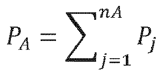
- the power generators are connected in two groups by opening the bridge switch Sb3, ie in this example three of the power generators (G 1 , G 2 and G 3 ) are in a first sub-arrangement A to provide a first pulse power P.
- A P 1 + P 2 + P 3
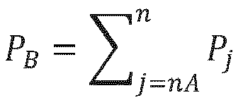
- the other three power generators (G 4 , G 5 , G 6 ) in a second sub-arrangement B for providing a second pulse power P B P 4 + P 5 + P 6 , analogously interconnected.
- three of the sputtering cathodes to the first sub-arrangement and the other three sputtering cathodes to the second sub-arrangement are made accessible in such a way that, for example, the sputtering cathodes T 1 , T 2 and T 3 with the first pulse power P A and the other three sputtering cathodes T 4 , T 5 and T 6 are fed with the second pulse power P B in a pulsed and sequential manner.
- the IGBT switches Sp1 to Sp3 and Sp4 to Sp6 can now be connected in completely separate pulse sequences or synchronous pulse sequences with the same or different pulse times t i and also with the same or different periods T A and T B.
- the mean sputtering power Pav i per sputtering cathode in the sub-arrangement in Figure 5 however remains the same as in the sputtering arrangement in FIG Figure 4 .
- the total coating rate with the interconnection of these two sub-arrangements is greater than with the interconnection of a single sputtering arrangement, as in Figure 4 .
- FIG. 6a, b shows a third analogous interconnection of the inventive sputtering arrangement, which according to the invention also as already in FIG Figure 4 and in the Figure 5 can be interconnected.
- All bridge switches are opened.
- Each sputtering cathode T i is assigned to a single power generator.
- the sputtering power Pc for each sputtering cathode T i then corresponds to P j .
- the sputtering power density is thus further reduced.
- the average sputtering power is the same as in the interconnections in FIG Fig. 4 and Fig. 5 .
- the coating rate is shown greater compared to that from the settings in Fig. 4 and Fig. 5 .
- Figure 7 shows the coating rate gain when switching the sputtering arrangement according to the invention from the connection in FIG Figure 4 on the interconnection in Figure 5 .
- Different sputtering materials were used in sputtering cathodes according to the settings in the examples in FIG Fig. 4 and Fig. 5 wired and corresponding layers were deposited.
- the sputtering power density was in the case of the connection according to Fig. 4 1800W / cm 2 and in the case of interconnection according to Fig. 5 900W / cm 2 .
- the mean sputtering power was the same in both cases.
- a coating rate increase as in Fig. 7 shown. If one had the power density in the sputtering arrangement with the interconnection according to Fig. 4 reduced by reducing the pulse power P, the coating rate would also have been reduced practically by half and no coating rate gain, and therefore no productivity gain.
- the present invention discloses:
- Interconnection variant with at least two sputtering sub-arrangements is switched over, a coating rate gain being achieved in comparison with a HiPIMS method, which would be carried out with the sputter arrangement in a first interconnection variant.
Landscapes
- Chemical & Material Sciences (AREA)
- Engineering & Computer Science (AREA)
- Physics & Mathematics (AREA)
- Plasma & Fusion (AREA)
- Analytical Chemistry (AREA)
- Chemical Kinetics & Catalysis (AREA)
- Materials Engineering (AREA)
- Mechanical Engineering (AREA)
- Metallurgy (AREA)
- Organic Chemistry (AREA)
- Physical Vapour Deposition (AREA)
Claims (13)
- Système de pulvérisation cathodique, le système de pulvérisation cathodique comprenant un nombre N de cathodes de pulvérisation ou de cathodes partielles de pulvérisation Ti avec i = 1 à N, et un nombre n de générateurs de puissance de pulvérisation Gj avec j = 1 à n, N étant un nombre entier et N ≥ 2 et n étant également un nombre entier et n ≥ 2; le système de pulvérisation cathodique comprenant des commutateurs en pont Sbj pour commuter les sorties de puissance Pj du générateur de puissance de pulvérisation respectif Gj, et des commutateurs à impulsion Spi pour distribuer les sorties de puissance respectives Pj aux cathodes de pulvérisation respectives T; le système de pulvérisation cathodique étant assemblé de manière à pouvoir fonctionner dans au moins deux variantes d'interconnexion différentes:- pour la première variante d'interconnexion, les sorties de puissance respectives Pj des n générateurs de puissance de pulvérisation Gj sont logiquement interconnectées au moyen des commutateurs en pont de sorte qu'une puissance totale de pulvérisation P est fournie, qui correspond à la somme des sorties de puissance Pj, c'est-à-dire

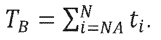
 - pour la seconde variante d'interconnexion, les cathodes de pulvérisation sont interconnectées du moins dans deux sous-systèmes de pulvérisation cathodique séparés A et B, pour faire fonctionner les sous-systèmes de pulvérisation cathodique les sorties de puissance d'un certain nombre nA de générateurs de pulvérisation cathodique et d'un certain nombre nB de générateurs de pulvérisation cathodique étant logiquement interconnectées au moyen des commutateurs en pont de sorte qu'une première puissance pulsée


- Installation de revêtement sous vide avec un système de pulvérisation cathodique selon la revendication 1, caractérisée en ce que le système de pulvérisation cathodique est assemblé de telle manière que, lors de l'exécution d'un procédé de pulvérisation cathodique, des impulsions de puissance élevée peuvent être utilisées, ce qui permet, lors de la pulvérisation cathodique, l'utilisation de densités de puissance élevée de 100 W/cm2 ou plus, en particulier 300 W/cm2 ou plus.
- Installation de revêtement sous vide selon la revendication 1 ou 2, caractérisée en ce que N = n.
- Installation de revêtement sous vide selon l'une des revendications 1 à 3, caractérisée en ce que PA = PB.
- Installation de revêtement sous vide selon l'une des revendications 1 à 4, caractérisée en ce que P = PA + PB.
- Installation de revêtement sous vide selon l'une des revendications 1 à 5, caractérisé en ce que NA = NB et/ou nA = nB.
- Procédé de revêtir des substrats au moyen de HiPIMS, le procédé HiPIMS étant réalisé dans une installation de revêtement sous vide avec un système de pulvérisation cathodique,
le système de pulvérisation cathodique comprenant un nombre N de cathodes de pulvérisation ou de cathodes partielles de pulvérisation Ti avec i = 1 à N, et un nombre n de générateurs de puissance de pulvérisation Gj avec j = 1 à n, N étant un nombre entier et N ≥ 2 et n étant également un nombre entier et n ≥ 2; le système de pulvérisation cathodique comprenant des commutateurs en pont Sbj pour commuter les sorties de puissance Pj du générateur de puissance de pulvérisation respectif Gj, et des commutateurs à impulsion Spi pour distribuer les sorties de puissance respectives Pj aux cathodes de pulvérisation respectives T; le système de pulvérisation cathodique étant assemblé de manière à pouvoir fonctionner dans au moins deux variantes d'interconnexion différentes:- pour la première variante d'interconnexion, les sorties de puissance respectives Pj des n générateurs de puissance de pulvérisation Gj sont logiquement interconnectées au moyen des commutateurs en pont de sorte qu'une puissance totale de pulvérisation P est fournie, qui correspond à la somme des sorties de puissance Pj, c'est-à-dire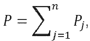
 - pour la seconde variante d'interconnexion, les cathodes de pulvérisation fonctionnent du moins dans deux sous-systèmes de pulvérisation cathodique séparés A et B, pour faire fonctionner les sous-systèmes de pulvérisation cathodique les sorties de puissance d'un certain nombre nA de générateurs de pulvérisation cathodique et d'un certain nombre nB de générateurs de pulvérisation cathodique étant logiquement interconnectées au moyen des commutateurs en pont de sorte qu'une première puissance pulsée PA =

- Procédé selon la revendication 7, caractérisé en ce qu'au moins pour déposer une couche au moyen de procédés HiPIMS, le système de pulvérisation cathodique est commuté sur une variante d'interconnexion avec au moins deux sous-systèmes de pulvérisation cathodique, un gain du taux de revêtement étant atteint par rapport à un procédé HiPIMS qui est réalisé au moyen du système de pulvérisation cathodique d'une première variante d'interconnexion.
- Procédé selon la revendication 7 ou 8, caractérisé en ce que le système de pulvérisation cathodique est assemblé de telle manière que pendant l'exécution d'un procédé de pulvérisation cathodique, des impulsions de puissance élevée peuvent être utilisées, ce qui permet l'utilisation de densités de puissance élevée de 100 W/cm2 ou plus, en particulier 300 W/cm2 ou plus, lors de la pulvérisation cathodique.
- Procédé selon l'une des revendications 7 à 9, caractérisé en ce que N = n.
- Procédé selon l'une des revendications 7 à 10, caractérisé en ce que PA = PB.
- Procédé selon l'une des revendications 7 à 11, caractérisé en ce que P = PA + PB.
- Procédé selon l'une des revendications 7 à 12, caractérisé en ce que NA = NB et/ou nA = nB.
Priority Applications (1)
| Application Number | Priority Date | Filing Date | Title |
|---|---|---|---|
| PL16798404T PL3375006T3 (pl) | 2015-11-12 | 2016-11-14 | Układ do napylania i sposób zoptymalizowanego rozkładu przepływu energii |
Applications Claiming Priority (2)
| Application Number | Priority Date | Filing Date | Title |
|---|---|---|---|
| US201562254451P | 2015-11-12 | 2015-11-12 | |
| PCT/EP2016/001891 WO2017080672A1 (fr) | 2015-11-12 | 2016-11-14 | Système de pulvérisation cathodique et procédé permettant une répartition optimisée du flux énergétique |
Publications (2)
| Publication Number | Publication Date |
|---|---|
| EP3375006A1 EP3375006A1 (fr) | 2018-09-19 |
| EP3375006B1 true EP3375006B1 (fr) | 2021-05-12 |
Family
ID=57354318
Family Applications (1)
| Application Number | Title | Priority Date | Filing Date |
|---|---|---|---|
| EP16798404.6A Active EP3375006B1 (fr) | 2015-11-12 | 2016-11-14 | Système de pulvérisation cathodique et procédé permettant une répartition optimisée du flux énergétique |
Country Status (17)
| Country | Link |
|---|---|
| US (1) | US10943774B2 (fr) |
| EP (1) | EP3375006B1 (fr) |
| JP (1) | JP6895432B2 (fr) |
| KR (1) | KR20180081776A (fr) |
| CN (1) | CN108352286B (fr) |
| BR (1) | BR112018009585B1 (fr) |
| CA (1) | CA3004920C (fr) |
| ES (1) | ES2883198T3 (fr) |
| HU (1) | HUE055816T2 (fr) |
| IL (1) | IL259263B (fr) |
| MX (1) | MX2018005902A (fr) |
| MY (1) | MY193962A (fr) |
| PH (1) | PH12018501018A1 (fr) |
| PL (1) | PL3375006T3 (fr) |
| RU (1) | RU2741614C2 (fr) |
| SG (1) | SG11201803970RA (fr) |
| WO (1) | WO2017080672A1 (fr) |
Families Citing this family (1)
| Publication number | Priority date | Publication date | Assignee | Title |
|---|---|---|---|---|
| JP7509790B2 (ja) | 2019-02-11 | 2024-07-02 | アプライド マテリアルズ インコーポレイテッド | パルスpvdにおけるプラズマ改質によるウエハからの粒子除去方法 |
Family Cites Families (8)
| Publication number | Priority date | Publication date | Assignee | Title |
|---|---|---|---|---|
| DE19651615C1 (de) * | 1996-12-12 | 1997-07-10 | Fraunhofer Ges Forschung | Verfahren zum Aufbringen von Kohlenstoffschichten durch reaktives Magnetron-Sputtern |
| US9771648B2 (en) * | 2004-08-13 | 2017-09-26 | Zond, Inc. | Method of ionized physical vapor deposition sputter coating high aspect-ratio structures |
| EP2272080B1 (fr) * | 2008-04-28 | 2012-08-01 | CemeCon AG | Dispositif et procede de pretraitement et de revetement de corps |
| RU2371514C1 (ru) * | 2008-08-20 | 2009-10-27 | Государственное образовательное учреждение высшего профессионального образования "Томский политехнический университет" | Дуальная магнетронная распылительная система |
| DE102008050499B4 (de) * | 2008-10-07 | 2014-02-06 | Systec System- Und Anlagentechnik Gmbh & Co. Kg | PVD-Beschichtungsverfahren, Vorrichtung zur Durchführung des Verfahrens und nach dem Verfahren beschichtete Substrate |
| EP2700083B1 (fr) * | 2011-04-20 | 2015-04-22 | Oerlikon Surface Solutions AG, Trübbach | Procédé permettant de fournir des impulsions de puissance séquentielles |
| DE102011018363A1 (de) * | 2011-04-20 | 2012-10-25 | Oerlikon Trading Ag, Trübbach | Hochleistungszerstäubungsquelle |
| DE102011116576A1 (de) * | 2011-10-21 | 2013-04-25 | Oerlikon Trading Ag, Trübbach | Bohrer mit Beschichtung |
-
2016
- 2016-11-14 CA CA3004920A patent/CA3004920C/fr active Active
- 2016-11-14 US US15/775,827 patent/US10943774B2/en active Active
- 2016-11-14 WO PCT/EP2016/001891 patent/WO2017080672A1/fr active Application Filing
- 2016-11-14 CN CN201680066326.1A patent/CN108352286B/zh active Active
- 2016-11-14 KR KR1020187016175A patent/KR20180081776A/ko not_active Application Discontinuation
- 2016-11-14 PL PL16798404T patent/PL3375006T3/pl unknown
- 2016-11-14 SG SG11201803970RA patent/SG11201803970RA/en unknown
- 2016-11-14 ES ES16798404T patent/ES2883198T3/es active Active
- 2016-11-14 JP JP2018524377A patent/JP6895432B2/ja active Active
- 2016-11-14 MX MX2018005902A patent/MX2018005902A/es unknown
- 2016-11-14 MY MYPI2018000736A patent/MY193962A/en unknown
- 2016-11-14 EP EP16798404.6A patent/EP3375006B1/fr active Active
- 2016-11-14 BR BR112018009585-0A patent/BR112018009585B1/pt active IP Right Grant
- 2016-11-14 RU RU2018120892A patent/RU2741614C2/ru active
- 2016-11-14 HU HUE16798404A patent/HUE055816T2/hu unknown
-
2018
- 2018-05-10 IL IL259263A patent/IL259263B/en unknown
- 2018-05-15 PH PH12018501018A patent/PH12018501018A1/en unknown
Non-Patent Citations (1)
| Title |
|---|
| None * |
Also Published As
| Publication number | Publication date |
|---|---|
| BR112018009585B1 (pt) | 2022-12-27 |
| IL259263A (en) | 2018-07-31 |
| CN108352286B (zh) | 2020-12-22 |
| ES2883198T3 (es) | 2021-12-07 |
| RU2018120892A (ru) | 2019-12-13 |
| US20180330931A1 (en) | 2018-11-15 |
| MX2018005902A (es) | 2019-04-04 |
| PL3375006T3 (pl) | 2021-11-22 |
| MY193962A (en) | 2022-11-03 |
| CA3004920A1 (fr) | 2017-05-18 |
| CA3004920C (fr) | 2024-01-23 |
| SG11201803970RA (en) | 2018-06-28 |
| KR20180081776A (ko) | 2018-07-17 |
| IL259263B (en) | 2022-04-01 |
| US10943774B2 (en) | 2021-03-09 |
| EP3375006A1 (fr) | 2018-09-19 |
| JP2018535323A (ja) | 2018-11-29 |
| JP6895432B2 (ja) | 2021-06-30 |
| PH12018501018A1 (en) | 2018-12-17 |
| CN108352286A (zh) | 2018-07-31 |
| HUE055816T2 (hu) | 2021-12-28 |
| RU2741614C2 (ru) | 2021-01-27 |
| BR112018009585A2 (pt) | 2018-12-04 |
| WO2017080672A1 (fr) | 2017-05-18 |
| RU2018120892A3 (fr) | 2020-01-30 |
Similar Documents
| Publication | Publication Date | Title |
|---|---|---|
| EP2700082B1 (fr) | Procédé de revêtement de substrats et source de pulvérisation haute puissance associée | |
| EP1864313B1 (fr) | Generateur de plasma sous vide | |
| EP0755461B1 (fr) | Procede et dispositif de revetement par evaporation sous vide par voie ionique | |
| DE102008021912B4 (de) | Beschichtungsverfahren und Vorrichtung zum Beschichten | |
| DE19702187C2 (de) | Verfahren und Einrichtung zum Betreiben von Magnetronentladungen | |
| EP2272080B1 (fr) | Dispositif et procede de pretraitement et de revetement de corps | |
| WO2012089286A1 (fr) | Dispositif de revêtement comprenant une source de puissance hipims (pulvérisation à magnétron pulsé à haute puissance) | |
| EP2700083B1 (fr) | Procédé permettant de fournir des impulsions de puissance séquentielles | |
| EP2771901B1 (fr) | Procédé permettant de fournir des impulsions de puissance séquentielles | |
| WO2007054048A1 (fr) | Procede et dispositif de revetement et/ou de traitement de surfaces | |
| DE19848636C2 (de) | Verfahren zur Überwachung einer Wechselspannungs-Entladung an einer Doppelelektrode | |
| EP2777061B1 (fr) | Couches hipims | |
| WO2013083238A1 (fr) | Procédé de pulvérisation cathodique réactive | |
| EP2140543A2 (fr) | Installation à plasma magnétron | |
| EP2439763B1 (fr) | Dispositif de magnétron et procédé de fonctionnement pulsé d'un dispositif à magnétron | |
| EP3375006B1 (fr) | Système de pulvérisation cathodique et procédé permettant une répartition optimisée du flux énergétique | |
| DE102016116762B4 (de) | Verfahren zum Abscheiden einer Schicht mittels einer Magnetronsputtereinrichtung | |
| DE10051508C2 (de) | Verfahren und Einrichtung zur Reduzierung der Zündspannung von Leistungspulsen gepulst betriebener Plasmen | |
| WO2007076793A1 (fr) | Procédé et dispositif de génération d’un système de champs magnétiques | |
| DE102011121770A1 (de) | Homogenes HIPIMS-Beschichtungsverfahren | |
| DE102010007516A1 (de) | Großflächige Kathode für Plasmaprozesse mit hohem Ionisierungsgrad | |
| DE102009019422B4 (de) | Verfahren zum Erzeugen eines Plasmas mittels eines Magnetrons | |
| EP0725161A1 (fr) | Procédé pour le traitement au plasma de pièces | |
| DE102021111097B4 (de) | Hohlkathodensystem zum Erzeugen eines Plasmas und Verfahren zum Betreiben eines solchen Hohlkathodensystems | |
| DE102012107163A1 (de) | Verfahren zur Beschichtung eines Substrats mittels Hochenergieimpulsmagnetronsputtern |
Legal Events
| Date | Code | Title | Description |
|---|---|---|---|
| STAA | Information on the status of an ep patent application or granted ep patent |
Free format text: STATUS: UNKNOWN |
|
| STAA | Information on the status of an ep patent application or granted ep patent |
Free format text: STATUS: THE INTERNATIONAL PUBLICATION HAS BEEN MADE |
|
| PUAI | Public reference made under article 153(3) epc to a published international application that has entered the european phase |
Free format text: ORIGINAL CODE: 0009012 |
|
| STAA | Information on the status of an ep patent application or granted ep patent |
Free format text: STATUS: REQUEST FOR EXAMINATION WAS MADE |
|
| 17P | Request for examination filed |
Effective date: 20180511 |
|
| AK | Designated contracting states |
Kind code of ref document: A1 Designated state(s): AL AT BE BG CH CY CZ DE DK EE ES FI FR GB GR HR HU IE IS IT LI LT LU LV MC MK MT NL NO PL PT RO RS SE SI SK SM TR |
|
| AX | Request for extension of the european patent |
Extension state: BA ME |
|
| DAV | Request for validation of the european patent (deleted) | ||
| DAX | Request for extension of the european patent (deleted) | ||
| GRAP | Despatch of communication of intention to grant a patent |
Free format text: ORIGINAL CODE: EPIDOSNIGR1 |
|
| STAA | Information on the status of an ep patent application or granted ep patent |
Free format text: STATUS: GRANT OF PATENT IS INTENDED |
|
| INTG | Intention to grant announced |
Effective date: 20200731 |
|
| GRAJ | Information related to disapproval of communication of intention to grant by the applicant or resumption of examination proceedings by the epo deleted |
Free format text: ORIGINAL CODE: EPIDOSDIGR1 |
|
| STAA | Information on the status of an ep patent application or granted ep patent |
Free format text: STATUS: REQUEST FOR EXAMINATION WAS MADE |
|
| GRAP | Despatch of communication of intention to grant a patent |
Free format text: ORIGINAL CODE: EPIDOSNIGR1 |
|
| STAA | Information on the status of an ep patent application or granted ep patent |
Free format text: STATUS: GRANT OF PATENT IS INTENDED |
|
| INTC | Intention to grant announced (deleted) | ||
| INTG | Intention to grant announced |
Effective date: 20201208 |
|
| GRAS | Grant fee paid |
Free format text: ORIGINAL CODE: EPIDOSNIGR3 |
|
| GRAA | (expected) grant |
Free format text: ORIGINAL CODE: 0009210 |
|
| STAA | Information on the status of an ep patent application or granted ep patent |
Free format text: STATUS: THE PATENT HAS BEEN GRANTED |
|
| AK | Designated contracting states |
Kind code of ref document: B1 Designated state(s): AL AT BE BG CH CY CZ DE DK EE ES FI FR GB GR HR HU IE IS IT LI LT LU LV MC MK MT NL NO PL PT RO RS SE SI SK SM TR |
|
| REG | Reference to a national code |
Ref country code: GB Ref legal event code: FG4D Free format text: NOT ENGLISH |
|
| REG | Reference to a national code |
Ref country code: CH Ref legal event code: EP |
|
| REG | Reference to a national code |
Ref country code: DE Ref legal event code: R096 Ref document number: 502016013041 Country of ref document: DE |
|
| REG | Reference to a national code |
Ref country code: IE Ref legal event code: FG4D Free format text: LANGUAGE OF EP DOCUMENT: GERMAN |
|
| REG | Reference to a national code |
Ref country code: AT Ref legal event code: REF Ref document number: 1392734 Country of ref document: AT Kind code of ref document: T Effective date: 20210615 |
|
| REG | Reference to a national code |
Ref country code: NL Ref legal event code: FP |
|
| REG | Reference to a national code |
Ref country code: SE Ref legal event code: TRGR |
|
| REG | Reference to a national code |
Ref country code: LT Ref legal event code: MG9D |
|
| REG | Reference to a national code |
Ref country code: SK Ref legal event code: T3 Ref document number: E 37893 Country of ref document: SK |
|
| PG25 | Lapsed in a contracting state [announced via postgrant information from national office to epo] |
Ref country code: BG Free format text: LAPSE BECAUSE OF FAILURE TO SUBMIT A TRANSLATION OF THE DESCRIPTION OR TO PAY THE FEE WITHIN THE PRESCRIBED TIME-LIMIT Effective date: 20210812 Ref country code: HR Free format text: LAPSE BECAUSE OF FAILURE TO SUBMIT A TRANSLATION OF THE DESCRIPTION OR TO PAY THE FEE WITHIN THE PRESCRIBED TIME-LIMIT Effective date: 20210512 Ref country code: LT Free format text: LAPSE BECAUSE OF FAILURE TO SUBMIT A TRANSLATION OF THE DESCRIPTION OR TO PAY THE FEE WITHIN THE PRESCRIBED TIME-LIMIT Effective date: 20210512 Ref country code: FI Free format text: LAPSE BECAUSE OF FAILURE TO SUBMIT A TRANSLATION OF THE DESCRIPTION OR TO PAY THE FEE WITHIN THE PRESCRIBED TIME-LIMIT Effective date: 20210512 |
|
| PG25 | Lapsed in a contracting state [announced via postgrant information from national office to epo] |
Ref country code: RS Free format text: LAPSE BECAUSE OF FAILURE TO SUBMIT A TRANSLATION OF THE DESCRIPTION OR TO PAY THE FEE WITHIN THE PRESCRIBED TIME-LIMIT Effective date: 20210512 Ref country code: NO Free format text: LAPSE BECAUSE OF FAILURE TO SUBMIT A TRANSLATION OF THE DESCRIPTION OR TO PAY THE FEE WITHIN THE PRESCRIBED TIME-LIMIT Effective date: 20210812 Ref country code: PT Free format text: LAPSE BECAUSE OF FAILURE TO SUBMIT A TRANSLATION OF THE DESCRIPTION OR TO PAY THE FEE WITHIN THE PRESCRIBED TIME-LIMIT Effective date: 20210913 Ref country code: GR Free format text: LAPSE BECAUSE OF FAILURE TO SUBMIT A TRANSLATION OF THE DESCRIPTION OR TO PAY THE FEE WITHIN THE PRESCRIBED TIME-LIMIT Effective date: 20210813 Ref country code: LV Free format text: LAPSE BECAUSE OF FAILURE TO SUBMIT A TRANSLATION OF THE DESCRIPTION OR TO PAY THE FEE WITHIN THE PRESCRIBED TIME-LIMIT Effective date: 20210512 Ref country code: IS Free format text: LAPSE BECAUSE OF FAILURE TO SUBMIT A TRANSLATION OF THE DESCRIPTION OR TO PAY THE FEE WITHIN THE PRESCRIBED TIME-LIMIT Effective date: 20210912 |
|
| REG | Reference to a national code |
Ref country code: ES Ref legal event code: FG2A Ref document number: 2883198 Country of ref document: ES Kind code of ref document: T3 Effective date: 20211207 |
|
| REG | Reference to a national code |
Ref country code: HU Ref legal event code: AG4A Ref document number: E055816 Country of ref document: HU |
|
| PG25 | Lapsed in a contracting state [announced via postgrant information from national office to epo] |
Ref country code: RO Free format text: LAPSE BECAUSE OF FAILURE TO SUBMIT A TRANSLATION OF THE DESCRIPTION OR TO PAY THE FEE WITHIN THE PRESCRIBED TIME-LIMIT Effective date: 20210512 Ref country code: SM Free format text: LAPSE BECAUSE OF FAILURE TO SUBMIT A TRANSLATION OF THE DESCRIPTION OR TO PAY THE FEE WITHIN THE PRESCRIBED TIME-LIMIT Effective date: 20210512 Ref country code: DK Free format text: LAPSE BECAUSE OF FAILURE TO SUBMIT A TRANSLATION OF THE DESCRIPTION OR TO PAY THE FEE WITHIN THE PRESCRIBED TIME-LIMIT Effective date: 20210512 Ref country code: EE Free format text: LAPSE BECAUSE OF FAILURE TO SUBMIT A TRANSLATION OF THE DESCRIPTION OR TO PAY THE FEE WITHIN THE PRESCRIBED TIME-LIMIT Effective date: 20210512 |
|
| REG | Reference to a national code |
Ref country code: DE Ref legal event code: R097 Ref document number: 502016013041 Country of ref document: DE |
|
| PLBE | No opposition filed within time limit |
Free format text: ORIGINAL CODE: 0009261 |
|
| STAA | Information on the status of an ep patent application or granted ep patent |
Free format text: STATUS: NO OPPOSITION FILED WITHIN TIME LIMIT |
|
| 26N | No opposition filed |
Effective date: 20220215 |
|
| PG25 | Lapsed in a contracting state [announced via postgrant information from national office to epo] |
Ref country code: IS Free format text: LAPSE BECAUSE OF FAILURE TO SUBMIT A TRANSLATION OF THE DESCRIPTION OR TO PAY THE FEE WITHIN THE PRESCRIBED TIME-LIMIT Effective date: 20210912 Ref country code: AL Free format text: LAPSE BECAUSE OF FAILURE TO SUBMIT A TRANSLATION OF THE DESCRIPTION OR TO PAY THE FEE WITHIN THE PRESCRIBED TIME-LIMIT Effective date: 20210512 |
|
| PG25 | Lapsed in a contracting state [announced via postgrant information from national office to epo] |
Ref country code: MC Free format text: LAPSE BECAUSE OF FAILURE TO SUBMIT A TRANSLATION OF THE DESCRIPTION OR TO PAY THE FEE WITHIN THE PRESCRIBED TIME-LIMIT Effective date: 20210512 |
|
| PG25 | Lapsed in a contracting state [announced via postgrant information from national office to epo] |
Ref country code: IE Free format text: LAPSE BECAUSE OF NON-PAYMENT OF DUE FEES Effective date: 20211114 |
|
| REG | Reference to a national code |
Ref country code: AT Ref legal event code: MM01 Ref document number: 1392734 Country of ref document: AT Kind code of ref document: T Effective date: 20211114 |
|
| PG25 | Lapsed in a contracting state [announced via postgrant information from national office to epo] |
Ref country code: AT Free format text: LAPSE BECAUSE OF NON-PAYMENT OF DUE FEES Effective date: 20211114 |
|
| PG25 | Lapsed in a contracting state [announced via postgrant information from national office to epo] |
Ref country code: CY Free format text: LAPSE BECAUSE OF FAILURE TO SUBMIT A TRANSLATION OF THE DESCRIPTION OR TO PAY THE FEE WITHIN THE PRESCRIBED TIME-LIMIT Effective date: 20210512 |
|
| PGFP | Annual fee paid to national office [announced via postgrant information from national office to epo] |
Ref country code: NL Payment date: 20231124 Year of fee payment: 8 Ref country code: LU Payment date: 20231124 Year of fee payment: 8 |
|
| PGFP | Annual fee paid to national office [announced via postgrant information from national office to epo] |
Ref country code: SK Payment date: 20231030 Year of fee payment: 8 |
|
| PGFP | Annual fee paid to national office [announced via postgrant information from national office to epo] |
Ref country code: GB Payment date: 20231121 Year of fee payment: 8 |
|
| PGFP | Annual fee paid to national office [announced via postgrant information from national office to epo] |
Ref country code: ES Payment date: 20231218 Year of fee payment: 8 |
|
| PGFP | Annual fee paid to national office [announced via postgrant information from national office to epo] |
Ref country code: TR Payment date: 20231024 Year of fee payment: 8 Ref country code: SE Payment date: 20231123 Year of fee payment: 8 Ref country code: IT Payment date: 20231124 Year of fee payment: 8 Ref country code: HU Payment date: 20231027 Year of fee payment: 8 Ref country code: FR Payment date: 20231123 Year of fee payment: 8 Ref country code: DE Payment date: 20231127 Year of fee payment: 8 Ref country code: CZ Payment date: 20231114 Year of fee payment: 8 Ref country code: CH Payment date: 20231201 Year of fee payment: 8 |
|
| PGFP | Annual fee paid to national office [announced via postgrant information from national office to epo] |
Ref country code: PL Payment date: 20231020 Year of fee payment: 8 Ref country code: BE Payment date: 20231124 Year of fee payment: 8 |
|
| PG25 | Lapsed in a contracting state [announced via postgrant information from national office to epo] |
Ref country code: MK Free format text: LAPSE BECAUSE OF FAILURE TO SUBMIT A TRANSLATION OF THE DESCRIPTION OR TO PAY THE FEE WITHIN THE PRESCRIBED TIME-LIMIT Effective date: 20210512 |
|
| PG25 | Lapsed in a contracting state [announced via postgrant information from national office to epo] |
Ref country code: MT Free format text: LAPSE BECAUSE OF FAILURE TO SUBMIT A TRANSLATION OF THE DESCRIPTION OR TO PAY THE FEE WITHIN THE PRESCRIBED TIME-LIMIT Effective date: 20210512 |