EP3374925B1 - Systeme de traitement des images - Google Patents
Systeme de traitement des images Download PDFInfo
- Publication number
- EP3374925B1 EP3374925B1 EP16791584.2A EP16791584A EP3374925B1 EP 3374925 B1 EP3374925 B1 EP 3374925B1 EP 16791584 A EP16791584 A EP 16791584A EP 3374925 B1 EP3374925 B1 EP 3374925B1
- Authority
- EP
- European Patent Office
- Prior art keywords
- opt
- people
- location
- person
- local
- Prior art date
- Legal status (The legal status is an assumption and is not a legal conclusion. Google has not performed a legal analysis and makes no representation as to the accuracy of the status listed.)
- Active
Links
- 238000012545 processing Methods 0.000 title claims description 48
- 238000000034 method Methods 0.000 claims description 19
- 238000004422 calculation algorithm Methods 0.000 claims description 9
- 238000005259 measurement Methods 0.000 claims description 8
- 238000001514 detection method Methods 0.000 claims description 6
- 230000004931 aggregating effect Effects 0.000 claims 2
- 230000007246 mechanism Effects 0.000 description 15
- 238000005286 illumination Methods 0.000 description 8
- 230000033001 locomotion Effects 0.000 description 8
- 230000008569 process Effects 0.000 description 7
- 230000002776 aggregation Effects 0.000 description 6
- 238000004220 aggregation Methods 0.000 description 6
- 238000010586 diagram Methods 0.000 description 5
- 239000000284 extract Substances 0.000 description 4
- 230000000694 effects Effects 0.000 description 3
- 230000005855 radiation Effects 0.000 description 3
- 238000004458 analytical method Methods 0.000 description 2
- 230000008901 benefit Effects 0.000 description 2
- 238000006243 chemical reaction Methods 0.000 description 2
- 230000006854 communication Effects 0.000 description 2
- 238000004891 communication Methods 0.000 description 2
- 230000001419 dependent effect Effects 0.000 description 2
- 230000006870 function Effects 0.000 description 2
- 238000007726 management method Methods 0.000 description 2
- 239000011159 matrix material Substances 0.000 description 2
- 230000004044 response Effects 0.000 description 2
- 230000011664 signaling Effects 0.000 description 2
- 230000007175 bidirectional communication Effects 0.000 description 1
- 238000004590 computer program Methods 0.000 description 1
- 238000012517 data analytics Methods 0.000 description 1
- 238000005516 engineering process Methods 0.000 description 1
- 230000001815 facial effect Effects 0.000 description 1
- 238000001914 filtration Methods 0.000 description 1
- 230000003993 interaction Effects 0.000 description 1
- 238000012423 maintenance Methods 0.000 description 1
- 238000012544 monitoring process Methods 0.000 description 1
- 230000003287 optical effect Effects 0.000 description 1
- 238000013439 planning Methods 0.000 description 1
- 238000013139 quantization Methods 0.000 description 1
- 238000007619 statistical method Methods 0.000 description 1
- 230000002123 temporal effect Effects 0.000 description 1
- 238000004148 unit process Methods 0.000 description 1
- 238000001429 visible spectrum Methods 0.000 description 1
- PICXIOQBANWBIZ-UHFFFAOYSA-N zinc;1-oxidopyridine-2-thione Chemical class [Zn+2].[O-]N1C=CC=CC1=S.[O-]N1C=CC=CC1=S PICXIOQBANWBIZ-UHFFFAOYSA-N 0.000 description 1
Images


Classifications
-
- G—PHYSICS
- G06—COMPUTING; CALCULATING OR COUNTING
- G06V—IMAGE OR VIDEO RECOGNITION OR UNDERSTANDING
- G06V20/00—Scenes; Scene-specific elements
- G06V20/50—Context or environment of the image
- G06V20/52—Surveillance or monitoring of activities, e.g. for recognising suspicious objects
- G06V20/53—Recognition of crowd images, e.g. recognition of crowd congestion
-
- G—PHYSICS
- G06—COMPUTING; CALCULATING OR COUNTING
- G06V—IMAGE OR VIDEO RECOGNITION OR UNDERSTANDING
- G06V10/00—Arrangements for image or video recognition or understanding
- G06V10/94—Hardware or software architectures specially adapted for image or video understanding
-
- G—PHYSICS
- G06—COMPUTING; CALCULATING OR COUNTING
- G06F—ELECTRIC DIGITAL DATA PROCESSING
- G06F21/00—Security arrangements for protecting computers, components thereof, programs or data against unauthorised activity
- G06F21/60—Protecting data
- G06F21/62—Protecting access to data via a platform, e.g. using keys or access control rules
- G06F21/6218—Protecting access to data via a platform, e.g. using keys or access control rules to a system of files or objects, e.g. local or distributed file system or database
- G06F21/6245—Protecting personal data, e.g. for financial or medical purposes
-
- G—PHYSICS
- G06—COMPUTING; CALCULATING OR COUNTING
- G06V—IMAGE OR VIDEO RECOGNITION OR UNDERSTANDING
- G06V20/00—Scenes; Scene-specific elements
- G06V20/50—Context or environment of the image
- G06V20/52—Surveillance or monitoring of activities, e.g. for recognising suspicious objects
-
- G—PHYSICS
- G06—COMPUTING; CALCULATING OR COUNTING
- G06V—IMAGE OR VIDEO RECOGNITION OR UNDERSTANDING
- G06V40/00—Recognition of biometric, human-related or animal-related patterns in image or video data
- G06V40/10—Human or animal bodies, e.g. vehicle occupants or pedestrians; Body parts, e.g. hands
Definitions
- the present invention relates to an image processing system, for example for processing image data and extracting information relating to people in an area, such as a people count.
- a lighting system for illuminating an environment may comprise a plurality of luminaires, each of which, in turn, comprises a light source in the form of one or more lamps that emit configurable illumination into the environment.
- the lamps may for example be LED lamps, filament bulbs, gas discharge lamps etc.
- the luminaires may be inter-connected so as to form a lighting network.
- a gateway such as a lighting bridge, may be connected to the network.
- the gateway can be used to communicate control signals via the network to each of the luminaires, for example under the control of a general-purpose computer device connected to the gateway.
- the lighting network may have a mesh topology, whereby the luminaires themselves act as relays within the lighting network, relaying control signals between the gateway and other luminaires in the network.
- the network may have a star topology, whereby luminaires communicate with the gateway "directly” i.e. without relying on other luminaires to relay the control signals (though possibly via other dedicated network components).
- the network can have any suitable network topology e.g. based on a combination of star-like and mesh-like connections.
- the lighting network may for example operate in accordance with ZigBee protocols.
- the luminaires may also be equipped with sensor mechanisms.
- sensor mechanisms have been relatively unsophisticated.
- combinations of timers and motion sensors have been used to selectively activate luminaires in response to recently sensed movement in the environment.
- An example of such a motion sensor is a passive infra-red (“PIR”) motion sensor, which uses infrared radiation emitted from moving bodies to detect their motion.
- PIR passive infra-red
- More modern lighting systems can incorporate sensors into the lighting network, so as to allow the aggregation of sensor data from multiple sensors in the environment. Using suitable sensors, this allows the luminaires to share information on, say, occupancy, activity patterns, changes in temperature or humidity, daylight levels etc. This is sometimes referred to as connected lighting. Sensor signals may be communicated via the lighting network to the gateway, thereby making them available to (say) a general purpose computer device connected to the gateway.
- Such sensors have been used in a lighting system to extract information relating to people in the area covered by the lighting system.
- people counting techniques have been utilised to generate a count of people in the area based on the aggregation of sensor data from individual vision sensors or image capture devices.
- US 2005/012817 A1 discloses a system and method for selectively monitoring movement of one or more objects.
- People counting information may be used to enable applications such as safe optimisation, planning and maintenance, HVAC control and data analytics driven marketing.
- people count is needed as one of the input data for analysis.
- space optimisation a count of people in (pseudo) real time is needed to identify temporal and spatial usage patterns.
- a people counting system in such a people counting system an opt-out is enabled.
- the inventors have appreciated that it is critical that user privacy be taken into account when utilising such people counting technology. For instance, there may be users who do not want to reveal any information that may be perceived to give away information related to their presence.
- a user is a person in the environment where people counting may be implemented.
- aspects of the present invention enable users to opt-out of people counting. In some embodiments of the invention described later, this is achieved by indicating their position or location to the system.
- a people counting system is provided according to claim 1.
- aspects of the invention can be utilised as part of a smart lighting system with multiple luminaires.
- the user may indicate his/her position to the lighting system.
- the position (or location) is indicated with the opt-out request.
- the system can be implemented in a context where each luminaire has a local processor which receives raw image data from a local image capture device and supplies metrics to a central processor for aggregation.
- raw image data is supplied to a central processor which processes the image data and extracts information such as a people count.
- the present disclosure relates to a system and method for enabling users to opt-out of the system which extracts information relating to people in an environment, such as a people counting system, based on multiple image capture devices distributed over space.
- the image capture devices may take the form of cameras and are referred to herein as vision sensors.
- the system may be part of a smart lighting system.
- the opt-out system described herein is primarily location-based. Three embodiments are described for identifying the location of a user who wants to opt-out.
- luminaires have an associated beacon (e.g. coded light, RF) and a co-located vision sensor.
- the user is equipped with a user device which can make signal measurements related to his or her position (e.g. coded light signals, RF measurement or position estimated itself) and feed this back to the lighting system.
- a user can point to his/her position in a floor plan and signal location information to the system.
- the user opts-out by explicitly signalling (e.g. using visible light means) to a sensor in the system.
- the sensor may be one of the vision sensors/image capture devices or an existing infrared detector in a luminaire.
- the opt-out request 80 may be acted on in different ways to enable the opt-out as described in more detail in the following.
- One advantage of the arrangement described herein is that an opt-out may be enabled locally to users without affecting system level people counting functionality.
- a sensor system formed by multiple vision sensors (also referred to as image capture devices) in a connected system with a central processing unit (also referred to as a people count processor) offers data-enabled applications based on people counting with opt-out. Described below are (a) types of information element that can be used to be communicated from the vision sensors to the central processing unit, (b) meta-data elements that are made available at the central processing unit (and vision sensors), and (c) associated methods to enable an opt-out from the people counting method for individual users.
- the system is a connected lighting system, comprising multiple luminaires, with the vision sensors at the luminaires that are connected to the central processing unit in order to count people in a given region.
- the vision sensors are connected to the central processing unit via a bi-directional communication link.
- FIG. 1 illustrates an exemplary lighting system 1, which comprises a plurality of luminaires 4 installed in an environment 2, arranged to emit light in order to illuminate that environment 2.
- a gateway 10 is shown, to which each of the luminaires 4 is connected.
- the gateway 10 effects control of the luminaires 4 within the lighting system 1, and is sometimes referred to as a lighting bridge.
- the environment 2 is an indoor space, such as one or more rooms and/or corridors (or part thereof), or a partially-covered space such as a stadium or gazebo (or part thereof).
- the luminaires 4 are ceiling-mounted, so as to be able to illuminate the ground (e.g. floor) below them. They are arranged in a grid along two mutually perpendicular directions in the plane of the ceiling, so as to form two substantially parallel rows of luminaires 4, each row being formed by multiple luminaires 4. The rows have an approximately equal spacing, as do the individual luminaires 4 within each row.
- FIG. 2 shows a block diagram of a luminaire 4, representing the individual configuration of each luminaire 4 in the lighting system 1.
- the luminaire 4 comprises at least one lamp 5 such as an LED-based lamp (one or more LEDs), gas-discharge lamp or filament bulb, plus any associated housing or support.
- the luminaire 4 also comprises a vision sensor 6 in the form of a camera, which is collocated with the lamp 5; a local processor (formed of one or more processing units, e.g. CPUs, GPUs etc.) 11; a network interface 7, and a local memory 13 (formed of one or more memory units, such as DMA and/or RAM units) connected to the local processor 11.
- the camera 6 may is able to detect radiation from the luminaires 4 when illuminating the environment, and is preferably a visible light camera. However, the use of a thermal camera is not excluded.
- the vision sensor 6 is connected to supply, to the local processor 11, raw image data captured by the vision sensor 6, to which a local person detection algorithm is applied by local image processing code 12a executed on the local processor 11.
- the local person detection algorithm can operate in a number of ways based on any suitable image recognition techniques (e.g. facial recognition and/or body recognition). Based on this, the local person detection algorithm generates "presence metrics", for use in a determining a person count centrally.
- the local processor 11 is connected to the lamp 5, to allow local control code 12b executed on the local processor 11 it to control at least the level of illumination emitted by the lamp 5.
- Other illumination characteristic(s) such as colour may also be controllable.
- the luminaire 4 comprises multiple lamps 5, these may be individually controllable by the local processor 11, at least to some extent.
- different coloured lamps 5 may be provided, so that the overall colour balance can be controlled by separately controlling their individual illumination levels.
- the network interface 7 may be a wireless (e.g. 802.15.4, Thread, ZigBee, Wi-Fi, Bluetooth) or wired (e.g. Ethernet) network interface, and provides network connectivity, whereby the luminaires 4 in the lighting system 4 are able to form a lighting network and thereby connect to the gateway 10.
- the network can have any suitable network topology, for example a mesh topology, star topology or any other suitable topology that allows signals to be transmitted and received between each luminaire 4 and the gateway 10.
- the network interface 7 is connected to local processor 11, so as to allow the local processor 11 to receive external control signals via the network. These control the operation of the local control code 12a, and thereby allow the illumination of the lamp 5 to be controlled externally. This connection also allows the local processor 11 to transmit images captured by the vision sensor 6, to which the image quantization has been applied by the local image processing code 12a, to an external destination via the network.
- Figure 3 shows a perspective view of a first and a second of the luminaires (4a, 4b), comprising first and second light sources 5a, 5b and first and second vision sensors 6a, 6b, as described above.
- the first and second luminaires 4a, 4b are neighbouring luminaires i.e. adjacent one another in the grid, along one of the directions of the grid or along one of the diagonals of the grid.
- the respective lamp 5a, 5b of each of the luminaires 4a, 4b is arranged to emit illumination towards a surface 29 (the floor in this example), thereby illuminating the surface 29 below the luminaires 4.
- a surface 29 the floor in this example
- the illumination provided by the luminaires 4 renders the people 8 detectable by the vision sensors 6.
- the respective vision sensor 6a, 6b of each luminaire 4a, 4b has a limited field of view.
- the field of view defines a volume of space, marked by dotted lines in figure 3 , within which visible structure is detectable by that vision sensor 6a, 6b.
- Each vision sensor 6a, 6b is positioned to capture images of the respective portion (i.e. area) 30a, 30b of the surface 29 that is within its field of view ("sensing area”), directly below its respective luminaire 4a, 4b.
- the fields of view of the first and second vision sensors 4a, 4b overlap in the sense that there is a region of space within which structure is detectable by both vision sensors 6a, 6b.
- one of the borders 30R of the sensing area 30a of the first sensor 6a is within the sensor area 32b of the second sensor 6b ("second sensing area”).
- one of the borders 30L of the sensor area 32b of the second sensor 6b is within the sensor area 30a of the first sensor 6a ("first sensing area”).
- An area A is shown, which is the intersection of the first and second sensor areas 30a, 30b. The area A is the part of the surface 29 that is visible to both of the first and second sensors 6a, 6b ("sensor overlap").
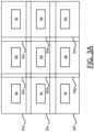
- Figure 3A shows a plan view of a part of the lighting system 1, in which a 3x3 gird of nine luminaires 4a,...,4h is shown, each having a respective sensor area 30a,...,30h, which is the sensor area of its respective vision sensor as described above.
- the sensing area of each luminaire overlaps with that of each of its neighbouring luminaires, in both directions along the gird and both directions diagonal to the grid, as shown.
- every pair of neighbouring luminaires (4a, 4b), (4a, 4c), (4a, 4d), (4b, 4c),... has an overlapping sensor area.
- the overlapping FoVs/sensing areas of the vision sensors ensure that there are no dead sensing regions.
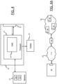
- FIG. 4 shows a block diagram of a central processing unit 20.
- the central processing unit is a computer device 20, such as a server, for operating the lighting system 1.
- the central processing unit 20 comprises a processor 21 (central processor), formed of e.g. one or more CPUs; and a network interface 23.
- the network interface 23 is connected to the central processor 21.
- the central processing unit 21 has access to a memory, formed of one or more memory devices, such as DMA and/or RAM devices.
- the memory 22 may be external or internal to the computer 20, or a combination of both (i.e. the memory 22 can, in some cases, denote a combination of internal and external memory devices), and in the latter case may be local or remote (i.e. accessed via a network).
- the processor 20 is connected to a display 25, which may for example be integrated in the computer device 20 or an external display.
- the processor 21 is shown executing lighting system management code 24.
- the lighting management applies an aggregation algorithm, to aggregate multiple local presence metrics received from different luminaires 4 so as to generate an estimate of the number of people 8 in the environment.
- the processor implements a first processing module connected to receive image data relating to the captured images of the image capture device and to extract information from the image data relating to people in the area.
- the network interface 23 can be a wired (e.g. Ethernet, USB, FireWire) or wireless (e.g. Wi-Fi, Bluetooth) network interface, and allows the central processing unit 20 to connect to the gateway 10 of the lighting system 1.
- the gateway 10 operates as an interface between the central processing unit 20 and the lighting network, and thus allows the central processing unit 20 to communicate with each of the luminaires 4 via the lighting network. In particular, this allows the central processing unit 20 to transmit control signals to each of the luminaires 4 and receive images from each of the luminaires 4.
- the gateway 10 provides any necessary protocol conversion to allow communication between the central processing unit 20 and the lighting network.
- FIGS. 2 and 4 are both highly schematic.
- the arrows denote high-level interactions between components of the luminaire 4 and central computer 20 and do not denote any specific configuration of local or physical connections.
- FIG. 4A shows an exemplary lighting system control architecture, in which the central processing unit 20 is connected to the gateway 10 via a packet basic network 42, which is a TCP/IP network in this example.
- the central processing unit 20 communicates with the gateway 10 via the packet based network 42 using TCP/IP protocols, which may for example be effected at the link layer using Ethernet protocols, Wi-Fi protocols, or a combination of both.
- the network 42 may for example be a local area network (business or home network), the Internet, or simply a direct wired (e.g. Ethernet) or wireless (e.g. Wi-Fi) connection between the central processing unit 20 and the gateway 10.
- the lighting network 44 is a ZigBee network in this example, in which the luminaires 4a, 4b, 4c,...
- the gateway 10 communicates with the gateway 10 using ZigBee protocols.
- the gateway 10 performs protocol conversion between TCP/IP and ZigBee protocols, so that the central computer 20 can communicate with the luminaires 4a, 4b, 4c via the packet based network 32, the gateway 10 and the lighting network 44.
- the memory 22 stores a database 22a.
- the database 22a contains a respective identifier (ID) of each vision sensor 6 (or each luminaire 4) in the lighting system 1, which uniquely identifies that vision sensor 6 within the lighting system 1, and an associated location identifier 71 of that vision sensor 6; for example, a two dimensional (x,y) or three dimensional location identifier 71 (x,y,z) (e.g. if the vision sensors are installed at different heights).
- the location identifier 71 may convey only relatively basic location information, such as a grid reference denoting the position of the corresponding luminaire in the grid - e.g.
- luminaires/vision sensors for the mth luminaire in the nth row, or it may convey a more accurate location of the vision sensor 6 (or luminaire 4) itself, e.g. in meters or feet to any desired accuracy.
- the IDs of luminaires/vision sensors, and their locations, are thus known to the central processing unit 20.
- the memory 22 may also store additional metadata, such as an indication of the sensor overlap A, and any other sensor overlaps in the system.
- additional metadata such as an indication of the sensor overlap A, and any other sensor overlaps in the system.
- some or all of the metadata 22b may be stored locally at the luminaires 4, as shown in figure 2 . In this case, each luminaire 4 may only store part of the metadata that applies to that luminaire and its neighbours.
- FIGS 5 and 5A illustrate how the central processor 20 and the luminaires 4 cooperate within the system 1.
- First, second and third luminaires 4a, 4b, 4c are shown, though this is purely exemplary.
- the vision sensors 6a, 6b, 6c of each luminaire captures at least one image 60a, 60b, 60c of its respective sensing area.
- the local processor 11a, 11b, 11c of that luminaire applies the local person detection algorithm to that image(s). That is, the local person detection algorithm is applied separately at each of the luminaires 4a, 4b, 4c, in parallel to generate a respective local presence metric 62a, 62b, 62c.
- Each of the local presence metrics 62a, 62b, 62c is transmitted to the central processing unit 20 via the networks 42, 44 and gateway 10.
- the images 60a, 60b, 60c themselves are not transmitted to the central processing unit 20.
- sensor overlap metadata 22b is used locally at the luminaires 4a, 4b, 4c to generate the local presence metrics.
- the central processing unit 20 applies the aggregation algorithm to the presence metrics 62a, 62b, 62c in order to estimate the number of people 8 in the environment.
- the aggregation algorithm generates an indicator of this number (people count) 64, which is outputted on the display 25 to a user of the central processing unit 20 and/or stored in the memory 22 for later use.
- the process may be real-time, in the sense that each local processor 11a, 11b, 11c repeatedly generates and transmits local presence metrics as new images are captured.
- the people count 64 is updated as the new presence metrics are received, for example one every few (e.g. 10 or fewer) seconds.
- the process may be pseudo-real-time e.g. such that the people count 64 is updated every minute or every few minutes, or every hour (for example), or it may be pseudo-static e.g. a "one-time" people count may be obtained in response to a count instruction from the user of the computer device 20, to obtain a snapshot of current occupancy levels manually. That is, each count may be instructed manually.
- Each presence metric 62 may be generated over a time window i.e. based on multiple images within that time window. This allows movements above a certain speed to be filtered out. I.e. objects moving fast enough to not appear in all of those images may be filtered out so that they do not affect the people count 64.
- Figure 5A shows an exemplary image 60 captured by the vision sensor 6a of the first luminaire 4a. A larger version of the image 60 is shown in figure 6 .
- a single person 61 is detectable in the image 60.
- the vision sensor 6a captures images of the part of the surface 29 directly below it, so the image 60a is a top-down view of the person 61, whereby the top of their head and shoulders are visible.
- the person 61 is in the sensor overlap area A, they would be similarly detectable in an image captured by the second luminaire 4b. That is the same person 61 would be simultaneously visible in images from both the first and second luminaires 4a, 4b, at different respective locations in those images.
- each vision sensor 6 (or rather the local image processor connected to that vision sensor 6) communicates a presence metric, along with its ID and a time stamp, to the central processing unit 20.
- Example presence metrics include:
- the central processing unit 20 collects such metrics from all vision sensors associated with a region over which people count is of interest (e.g. all or part of the surface 29). Additionally, the central processing unit 22 has knowledge of sensing region overlap of the vision sensors, from the metadata 22b. It aggregates the individual vision sensor counts while avoiding double-counts over overlapping regions within a given time window.
- a people counting system can be implemented with vision sensors/image capture devices 6.
- vision sensors/image capture devices 6 it has been perceived by the inventors that it is critical that user privacy be taken into account because users may have perceived concerns regarding privacy. For instance, there may be users that not want to reveal any information that may be perceived to give away information related to their presence. As such, the present disclosure provides a mechanism for such users to opt-out without compromising the people counting functionality at a higher level.
- the opt-out can be enforced/implemented in a number of different ways.
- the database 22a has an opt-out field 70 which can be turned on for the location of a user that has made the opt-out request.
- the local processor 11 which is associated with the particular one of the image capture devices 6 which receives the user opt-out request does not report locations of users that opt-out.
- the updating rate of the local processor 11 associated with the image capture device 6 is increased beyond a default value.
- the present disclosure describes two different infrastructures in which the opt-out can be implemented.
- a first infrastructure Figures 7 and 8
- multiple image capture devices 6 each feed data to a central processing unit.
- the central processing unit processes the image data, extracts information relating to the people in the area (for example, a people count) and also takes care of implementing the opt-out responsive to an opt-out request (as implemented using one of the example mechanisms described below in relation to Figures 11-13 ).
- the image data may be raw image data from each image capture device 6 ( Figure 7 ).
- the image data may be processed image data in the form of metrics from the local processor 11 associated with each image capture device 6.
- each image capture device 6 is associated with a local processor 11 which receives raw image data from the image capture device 6 and provides metrics to the central processing unit.
- the opt-out request 80 (as implemented using one of the example mechanisms described below in relation to Figures 11-13 ) is received at each local processor 11 in such a way that location information is not provided to the central processing unit at all, or is provided in a manner which disassociates it with the people in the area who have opted-out. This disassociation can be by changing the update rate of location information as compared to the people metrics.
- images are uploaded from the local image capture devices 6 to the main processor 20 (the people count processor 20).
- the people count processor 20 processes the images, extracts data and provides the people count.
- an opt-out request 80 is received by the processor and used to set an opt-out flag in the database 22a attached to the processor (or accessible by it). Then, when the processor is processing the information in the images, it does not use information relating to the locations where the opt-out flag is set.
- each image capture device 6 is attached to its own local processor 11 which processes the images and provides metrics (including location information) for the people count processor 20.
- the opt-out request 80 sets the opt-out flag in the database and then location information included in the metrics which have been sent to the people count processor are no longer taken into account for locations where the opt-out flag is set. That is, all the information (metrics) is provided to the people count processor 20, but metrics pertaining to location may be ignored responsive to an opt-out request, thus maintaining the people counting functionality of the people count processor 20 without violating the user's privacy. For example, a location vector of a user which is included in the metrics for that user may be ignored if the opt-out flag is set for a location ID corresponding to the location vector.
- the local processor 11 which receives the opt-out request 80 and acts on it to control the information which is supplied to the people count processor 20.
- a second processing module is implemented in each local processor, while a first processing module which processes the image data is implemented in the people count processor 20.
- the people count processor 20 does not receive location information. That is, the local processor 11 which receives the opt-out request filters out identifying information (location metrics) before passing the presence data to the people count processor 20.
- image data used herein is used to cover a situation where the image data are images themselves from an image capture device 6, or where the image data comprises metrics provided by local processors 11 from the raw images taken by the image capture devices 6.
- the presence information may be provided to the people count server 20 in real or pseudo-real time.
- location information may be provided, but updated at a different rate so that it is disassociated with the people-related information in the image data.
- the people count processor 20 still has access to all the metrics themselves, but in an unrelated form in which the location data of a user is separated from the actual people counting information (e.g. presence or no presence).
- a first processing module is provided to process the image data to extract information such as a people count.
- a second processing module receives the opt-out request 80 and implements the opt-out.
- the first and second processing modules may be in the same processor, or in different processors.
- luminaires transmit beacon signals 110a, 110b (for example, coded light or RF).
- the user has a device to make signal measurement related to his/her position using these beacons.
- the signal measurements may be, for example, coded light signals, RSSI measurements or similar.
- the user device computes a position estimate based on the signal measurement and supplies this estimated position as part of the opt-out request back to the lighting system, for example, using a coded light signal (illustrated by arrow 111).
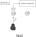
- a user may have a floor plan displayed on this device and is able to mark his or her location on the floor plan. As illustrated by arrow 121, this location information may then be signalled to the people counting system from the user device, either directly using coded light or via a messaging system through the network.
- a user may opt-out by explicit signalling, for example, using visible light, in which case the opt-out 80 request is a visible light opt-out request 131 which may be captured by a vision sensor/image capture device 6 of the system which can then use this to estimate the location of the originating signal. The estimated location is supplied with the opt-out request.
- the sensor could be an existing infrared director in a luminaire.
- the central database has an opt-out field that is turned on for locations that have made the opt-out request.
- the image capture device 6 associated with the user opt-out request does not report the location of users that opt-out - only a people count is reported, while opt-out locations are screened.
- the image capture location updating rate is increased beyond a default value.
- the image capture device 6 may still report a people count number as a default rate, while user locations themselves are reported at a much lower update rate. This has a consequence that user tracking is rendered ineffective, while it is still possible to get a count of people.
- the techniques can be applied in general to any lighting system (indoor, outdoor or a combination of both), in which vision sensors are deployed. For example, in an outdoor space such as a park or garden. Whilst it can be convenient to collocate the sensors with the luminaires for reasons discussed, this is by no means essential, nor is there any need to have the same number of luminaires and sensors. Moreover, the techniques need not be applied in a lighting system at all.
- the above-described architecture is exemplary.
- the techniques of this disclosure can be implemented in a more distributed fashion, e.g. without the gateway 10 or central processing unit 20.
- the functionality of the central processing unit 20 as described above may be implemented by the local processor 11 attached to one of the vision sensors 6 (which may or may not be collocated with a luminaire 4 in general), or distributed across multiple local processors 11.
- each of one, some, or all of the image sensors 6 may take the form of a thermal camera or thermopile array which capture thermal images based on infrared radiation.
- a computer program may be stored/distributed on a suitable medium, such as an optical storage medium or a solid-state medium supplied together with or as part of other hardware, but may also be distributed in other forms, such as via the Internet or other wired or wireless telecommunication systems. Any reference signs in the claims should not be construed as limiting the scope.
Claims (6)
- Système de comptage de personnes comprenant :- une pluralité de dispositifs de capture d'images agencés pour assurer la couverture d'une zone, dans lequel chaque dispositif de capture d'images (6) est agencé pour capturer des images (60) de la zone (30) et pour assurer une couverture individuelle d'une région de la zone dans son champ de vision ;
dans lequel chaque dispositif de capture d'images comprend un processeur d'images local configuré pour appliquer un algorithme de détection de personne local (12a) aux données d'images capturées, générant ainsi une mesure de présence locale (62) comprenant un décompte de présence indiquant un nombre de personnes détectées dans la région couverte et un identificateur d'emplacement de personne (71) identifiant un emplacement de chaque personne détectée dans la région couverte ;- un premier module de traitement (20) connecté pour recevoir la mesure de présence locale relative aux images capturées d'un dispositif de capture d'images, et fournir un décompte de personnes en agrégeant les mesures de présence locales provenant de la pluralité de dispositifs de capture d'images ;
dans lequel le processeur d'images local (11) est configuré pour recevoir à partir d'un dispositif utilisateur associé à l'une des personnes (61) dans la zone une demande d'exclusion (80) associée à cette personne, dans lequel la demande d'exclusion comporte des informations d'emplacement (71) indiquant l'emplacement réel ou estimé de la personne associée à la demande d'exclusion, et pour commander, en réponse à la demande d'exclusion, l'arrêt de la prise en compte de la mesure de présence locale d'emplacements de personnes qui se rapportent à l'emplacement de la personne associée à la demande d'exclusion. - Système de comptage de personnes selon la revendication 1, le système de comptage de personnes comprenant une pluralité de luminaires (4) agencés pour éclairer la zone, dans lequel chaque dispositif de capture d'images est colocalisé avec un luminaire respectif des luminaires.
- Système de comptage de personnes selon les revendications 1 et 2, qui comprend un dispositif de commande de balise respectif associé à chaque luminaire configuré pour transmettre un signal de mesure (110) au dispositif utilisateur associé à la personne exclue, moyennant quoi le dispositif utilisateur est amené à calculer une estimation de son emplacement sur la base de signaux de mesure provenant d'au moins deux dispositifs de commande de balise, et pour générer une demande d'exclusion comprenant l'estimation de son emplacement.
- Système de comptage de personnes selon la revendication 1, comprenant un capteur de vision, ledit capteur de vision comprenant le dispositif de capture d'images, configuré pour recevoir le signal d'exclusion sous la forme d'un signal visible (131), et des moyens pour estimer l'emplacement d'un émetteur du signal visible pour fournir les informations d'emplacement indiquant l'emplacement d'une personne exclue.
- Système de comptage de personnes selon l'une quelconque revendication précédente, dans lequel la demande d'exclusion définit une période de temps au cours de laquelle la personne est exclue.
- Procédé d'exclusion d'un système de comptage de personnes comprenant :la réception d'une mesure de présence locale relative à des images capturées d'une pluralité de dispositifs de capture d'images, chacun étant agencé pour fournir une couverture d'une région d'une zone dans son champ de vision ; dans lequel la mesure de présence locale (62) comprend un décompte de présence indiquant un nombre de personnes détectées dans la région couverte et un identificateur d'emplacement de personne (71) identifiant un emplacement de chaque personne détectée dans la région couverte ;la fourniture d'un décompte de personnes en agrégeant les mesures de présence de présence locales provenant de la pluralité de dispositifs de capture d'images ;la réception à partir d'un dispositif utilisateur associé à l'une des personnes dans la zone d'une demande d'exclusion associée à cette personne, dans lequel la demande d'exclusion comporte des informations d'emplacement (71) indiquant l'emplacement réel ou estimé de la personne associée à la demande d'exclusion ; etla commande, en réponse à la demande d'exclusion, pour arrêter de prendre en compte la mesure de présence locale d'emplacements de personnes qui se rapportent à la personne associée à la demande d'exclusion.
Applications Claiming Priority (2)
| Application Number | Priority Date | Filing Date | Title |
|---|---|---|---|
| EP15194185 | 2015-11-12 | ||
| PCT/EP2016/076718 WO2017080929A1 (fr) | 2015-11-12 | 2016-11-04 | Système de traitement d'images |
Publications (2)
| Publication Number | Publication Date |
|---|---|
| EP3374925A1 EP3374925A1 (fr) | 2018-09-19 |
| EP3374925B1 true EP3374925B1 (fr) | 2024-05-01 |
Family
ID=54608290
Family Applications (1)
| Application Number | Title | Priority Date | Filing Date |
|---|---|---|---|
| EP16791584.2A Active EP3374925B1 (fr) | 2015-11-12 | 2016-11-04 | Systeme de traitement des images |
Country Status (4)
| Country | Link |
|---|---|
| US (1) | US10878251B2 (fr) |
| EP (1) | EP3374925B1 (fr) |
| CN (1) | CN108292357B (fr) |
| WO (1) | WO2017080929A1 (fr) |
Families Citing this family (7)
| Publication number | Priority date | Publication date | Assignee | Title |
|---|---|---|---|---|
| WO2018064840A1 (fr) * | 2016-10-09 | 2018-04-12 | 浙江国自机器人技术有限公司 | Unité mobile, système de gestion d'articles de stock, et procédé permettant de positionner une unité mobile |
| FR3087920B1 (fr) * | 2018-10-26 | 2021-06-04 | Jcdecaux Sa | Dispositif de comptage de personnes et mobilier urbain comportant un tel dispositif |
| WO2020104254A1 (fr) | 2018-11-20 | 2020-05-28 | Signify Holding B.V. | Système de comptage de personnes doté de régions de détection agrégées |
| US11457099B2 (en) * | 2019-11-14 | 2022-09-27 | Hewlett Packard Enterprise Development Lp | Integrated local area networks (LANs) and personal area networks (PANs) |
| CN112949673B (zh) * | 2019-12-11 | 2023-04-07 | 四川大学 | 一种基于全局注意力的特征融合目标检测与识别方法 |
| US11520073B2 (en) | 2020-07-31 | 2022-12-06 | Analog Devices International Unlimited Company | Multiple sensor aggregation |
| CN116167705B (zh) * | 2022-12-01 | 2023-09-12 | 上海山源电子科技股份有限公司 | 受限区域人员统计方法、装置、电子设备及介质 |
Family Cites Families (27)
| Publication number | Priority date | Publication date | Assignee | Title |
|---|---|---|---|---|
| JP2000223282A (ja) | 1999-01-27 | 2000-08-11 | Mitsubishi Electric Corp | 照明制御装置 |
| AU2002252294A1 (en) | 2001-03-09 | 2002-09-24 | Radianse, Inc. | A system and method for performing object association at a tradeshow using a location tracking system |
| US20040203630A1 (en) * | 2002-03-15 | 2004-10-14 | Wang Charles Chuanming | Method and apparatus for targeting service delivery to mobile devices |
| US20050012817A1 (en) | 2003-07-15 | 2005-01-20 | International Business Machines Corporation | Selective surveillance system with active sensor management policies |
| CN1710606A (zh) * | 2004-06-18 | 2005-12-21 | 上海印钞厂 | 一种非接触式视觉纸张计数方法和计数机 |
| JP4607676B2 (ja) * | 2005-06-13 | 2011-01-05 | 株式会社ブレインズ | 停止人数計数装置 |
| US8264584B2 (en) * | 2007-05-31 | 2012-09-11 | Panasonic Corporation | Image capturing apparatus, additional information providing server, and additional information filtering system |
| US20100024045A1 (en) * | 2007-06-30 | 2010-01-28 | Sastry Manoj R | Methods and apparatuses for privacy in location-aware systems |
| US8411963B2 (en) * | 2008-08-08 | 2013-04-02 | The Nielsen Company (U.S.), Llc | Methods and apparatus to count persons in a monitored environment |
| US7890625B2 (en) * | 2008-09-29 | 2011-02-15 | Cisco Technology, Inc. | Method and apparatus for network to recommend best mode for user communication |
| US8446288B2 (en) | 2008-10-15 | 2013-05-21 | Panasonic Corporation | Light projection device |
| CN101706976A (zh) * | 2009-08-26 | 2010-05-12 | 深圳市飞瑞斯科技有限公司 | 一种基于视频人数统计防尾随的系统和装置 |
| US20130038694A1 (en) | 2010-04-27 | 2013-02-14 | Sanjay Nichani | Method for moving object detection using an image sensor and structured light |
| IL208910A0 (en) * | 2010-10-24 | 2011-02-28 | Rafael Advanced Defense Sys | Tracking and identification of a moving object from a moving sensor using a 3d model |
| CN104335683B (zh) * | 2012-06-04 | 2018-04-27 | 飞利浦灯具控股公司 | 一种用于在联网照明控制系统中提供隐私保护的方法 |
| JP2015529869A (ja) | 2012-06-12 | 2015-10-08 | センシティ システムズ インコーポレイテッド | 照明インフラストラクチャおよび収益モデル |
| JP2014017114A (ja) * | 2012-07-09 | 2014-01-30 | Panasonic Corp | 照明システム |
| US9208676B2 (en) | 2013-03-14 | 2015-12-08 | Google Inc. | Devices, methods, and associated information processing for security in a smart-sensored home |
| MY186672A (en) | 2013-01-30 | 2021-08-05 | Mimos Berhad | Directing steerable camera with user bias tracking |
| US20140240493A1 (en) * | 2013-02-28 | 2014-08-28 | Jong Suk Bang | Sensor lighting with image recording unit |
| US9866900B2 (en) * | 2013-03-12 | 2018-01-09 | The Nielsen Company (Us), Llc | Methods, apparatus and articles of manufacture to detect shapes |
| US9697533B2 (en) * | 2013-04-17 | 2017-07-04 | The Nielsen Company (Us), Llc | Methods and apparatus to monitor media presentations |
| EP4006860A1 (fr) | 2013-04-23 | 2022-06-01 | Canary Connect, Inc. | Dispositifs et systèmes de sécurité et/ou de surveillance |
| US9165444B2 (en) | 2013-07-26 | 2015-10-20 | SkyBell Technologies, Inc. | Light socket cameras |
| CN104093008B (zh) * | 2014-08-01 | 2017-12-15 | 北京奇虎科技有限公司 | 摄像装置、视频监控系统以及视频监控方法 |
| US9460615B2 (en) * | 2014-09-12 | 2016-10-04 | Umm Al-Qura University | Automatic update of crowd and traffic data using device monitoring |
| CN104320760B (zh) * | 2014-10-17 | 2018-09-21 | 厦门美图移动科技有限公司 | 一种位置请求处理设备和方法和位置信息获取设备和方法 |
-
2016
- 2016-11-04 WO PCT/EP2016/076718 patent/WO2017080929A1/fr active Application Filing
- 2016-11-04 EP EP16791584.2A patent/EP3374925B1/fr active Active
- 2016-11-04 US US15/775,404 patent/US10878251B2/en active Active
- 2016-11-04 CN CN201680066165.6A patent/CN108292357B/zh active Active
Also Published As
| Publication number | Publication date |
|---|---|
| CN108292357B (zh) | 2023-02-24 |
| EP3374925A1 (fr) | 2018-09-19 |
| US20180336420A1 (en) | 2018-11-22 |
| US10878251B2 (en) | 2020-12-29 |
| CN108292357A (zh) | 2018-07-17 |
| WO2017080929A1 (fr) | 2017-05-18 |
Similar Documents
| Publication | Publication Date | Title |
|---|---|---|
| EP3374925B1 (fr) | Systeme de traitement des images | |
| EP3414746B1 (fr) | Système de détection de personnes | |
| JP6467112B2 (ja) | センサシステムのコミッショニング | |
| US10671826B2 (en) | Indoor location services using a distributed lighting network | |
| US20170027045A1 (en) | Intelligent lighting systems and methods for monitoring, analysis, and automation of the built environment | |
| CN108738356A (zh) | 使用射频信号和传感器以监控环境的系统和方法 | |
| WO2017060083A1 (fr) | Système de comptage de personnes et d'éclairage intégré | |
| CN109691234B (zh) | 照明传感器分析 | |
| US9877369B2 (en) | Lighting device and method for managing a lighting system | |
| WO2017076715A1 (fr) | Système de détection des personnes | |
| WO2017108374A1 (fr) | Système de capteur | |
| US10299355B2 (en) | Intelligent gating mechanism | |
| TWI813968B (zh) | 封閉環境中的活動監控系統和方法 | |
| US20230180371A1 (en) | Detection and identification of auditory events in distributed lighting networks | |
| WO2017108408A1 (fr) | Système de capteur | |
| EP3326080A1 (fr) | Systèmes et procédés d'éclairage intelligent pour la surveillance, l'analyse et l'automation de l'environnement bâti | |
| CN113785666B (zh) | 照明设备 |
Legal Events
| Date | Code | Title | Description |
|---|---|---|---|
| STAA | Information on the status of an ep patent application or granted ep patent |
Free format text: STATUS: UNKNOWN |
|
| STAA | Information on the status of an ep patent application or granted ep patent |
Free format text: STATUS: THE INTERNATIONAL PUBLICATION HAS BEEN MADE |
|
| PUAI | Public reference made under article 153(3) epc to a published international application that has entered the european phase |
Free format text: ORIGINAL CODE: 0009012 |
|
| STAA | Information on the status of an ep patent application or granted ep patent |
Free format text: STATUS: REQUEST FOR EXAMINATION WAS MADE |
|
| 17P | Request for examination filed |
Effective date: 20180612 |
|
| AK | Designated contracting states |
Kind code of ref document: A1 Designated state(s): AL AT BE BG CH CY CZ DE DK EE ES FI FR GB GR HR HU IE IS IT LI LT LU LV MC MK MT NL NO PL PT RO RS SE SI SK SM TR |
|
| AX | Request for extension of the european patent |
Extension state: BA ME |
|
| RAP1 | Party data changed (applicant data changed or rights of an application transferred) |
Owner name: PHILIPS LIGHTING HOLDING B.V. |
|
| DAV | Request for validation of the european patent (deleted) | ||
| DAX | Request for extension of the european patent (deleted) | ||
| RAP1 | Party data changed (applicant data changed or rights of an application transferred) |
Owner name: SIGNIFY HOLDING B.V. |
|
| STAA | Information on the status of an ep patent application or granted ep patent |
Free format text: STATUS: EXAMINATION IS IN PROGRESS |
|
| 17Q | First examination report despatched |
Effective date: 20210205 |
|
| STAA | Information on the status of an ep patent application or granted ep patent |
Free format text: STATUS: EXAMINATION IS IN PROGRESS |
|
| REG | Reference to a national code |
Ref document number: 602016087305 Country of ref document: DE Ref country code: DE Ref legal event code: R079 Free format text: PREVIOUS MAIN CLASS: G06K0009000000 Ipc: G06V0010940000 |
|
| GRAP | Despatch of communication of intention to grant a patent |
Free format text: ORIGINAL CODE: EPIDOSNIGR1 |
|
| STAA | Information on the status of an ep patent application or granted ep patent |
Free format text: STATUS: GRANT OF PATENT IS INTENDED |
|
| INTG | Intention to grant announced |
Effective date: 20231130 |
|
| RIC1 | Information provided on ipc code assigned before grant |
Ipc: G06V 20/52 20220101ALI20231117BHEP Ipc: G06V 10/94 20220101AFI20231117BHEP |
|
| GRAS | Grant fee paid |
Free format text: ORIGINAL CODE: EPIDOSNIGR3 |
|
| GRAA | (expected) grant |
Free format text: ORIGINAL CODE: 0009210 |
|
| STAA | Information on the status of an ep patent application or granted ep patent |
Free format text: STATUS: THE PATENT HAS BEEN GRANTED |
|
| P01 | Opt-out of the competence of the unified patent court (upc) registered |
Effective date: 20240312 |
|
| AK | Designated contracting states |
Kind code of ref document: B1 Designated state(s): AL AT BE BG CH CY CZ DE DK EE ES FI FR GB GR HR HU IE IS IT LI LT LU LV MC MK MT NL NO PL PT RO RS SE SI SK SM TR |
|
| REG | Reference to a national code |
Ref country code: GB Ref legal event code: FG4D |