EP3374711B1 - Gekühltes verkaufsmöbelstück - Google Patents
Gekühltes verkaufsmöbelstück Download PDFInfo
- Publication number
- EP3374711B1 EP3374711B1 EP15793813.5A EP15793813A EP3374711B1 EP 3374711 B1 EP3374711 B1 EP 3374711B1 EP 15793813 A EP15793813 A EP 15793813A EP 3374711 B1 EP3374711 B1 EP 3374711B1
- Authority
- EP
- European Patent Office
- Prior art keywords
- refrigerated sales
- products
- furniture
- refrigerated
- identification device
- Prior art date
- Legal status (The legal status is an assumption and is not a legal conclusion. Google has not performed a legal analysis and makes no representation as to the accuracy of the status listed.)
- Active
Links
Images
Classifications
-
- F—MECHANICAL ENGINEERING; LIGHTING; HEATING; WEAPONS; BLASTING
- F25—REFRIGERATION OR COOLING; COMBINED HEATING AND REFRIGERATION SYSTEMS; HEAT PUMP SYSTEMS; MANUFACTURE OR STORAGE OF ICE; LIQUEFACTION SOLIDIFICATION OF GASES
- F25D—REFRIGERATORS; COLD ROOMS; ICE-BOXES; COOLING OR FREEZING APPARATUS NOT OTHERWISE PROVIDED FOR
- F25D29/00—Arrangement or mounting of control or safety devices
-
- F—MECHANICAL ENGINEERING; LIGHTING; HEATING; WEAPONS; BLASTING
- F25—REFRIGERATION OR COOLING; COMBINED HEATING AND REFRIGERATION SYSTEMS; HEAT PUMP SYSTEMS; MANUFACTURE OR STORAGE OF ICE; LIQUEFACTION SOLIDIFICATION OF GASES
- F25D—REFRIGERATORS; COLD ROOMS; ICE-BOXES; COOLING OR FREEZING APPARATUS NOT OTHERWISE PROVIDED FOR
- F25D2500/00—Problems to be solved
- F25D2500/06—Stock management
-
- F—MECHANICAL ENGINEERING; LIGHTING; HEATING; WEAPONS; BLASTING
- F25—REFRIGERATION OR COOLING; COMBINED HEATING AND REFRIGERATION SYSTEMS; HEAT PUMP SYSTEMS; MANUFACTURE OR STORAGE OF ICE; LIQUEFACTION SOLIDIFICATION OF GASES
- F25D—REFRIGERATORS; COLD ROOMS; ICE-BOXES; COOLING OR FREEZING APPARATUS NOT OTHERWISE PROVIDED FOR
- F25D2700/00—Means for sensing or measuring; Sensors therefor
- F25D2700/06—Sensors detecting the presence of a product
-
- F—MECHANICAL ENGINEERING; LIGHTING; HEATING; WEAPONS; BLASTING
- F25—REFRIGERATION OR COOLING; COMBINED HEATING AND REFRIGERATION SYSTEMS; HEAT PUMP SYSTEMS; MANUFACTURE OR STORAGE OF ICE; LIQUEFACTION SOLIDIFICATION OF GASES
- F25D—REFRIGERATORS; COLD ROOMS; ICE-BOXES; COOLING OR FREEZING APPARATUS NOT OTHERWISE PROVIDED FOR
- F25D2700/00—Means for sensing or measuring; Sensors therefor
- F25D2700/08—Sensors using Radio Frequency Identification [RFID]
-
- F—MECHANICAL ENGINEERING; LIGHTING; HEATING; WEAPONS; BLASTING
- F25—REFRIGERATION OR COOLING; COMBINED HEATING AND REFRIGERATION SYSTEMS; HEAT PUMP SYSTEMS; MANUFACTURE OR STORAGE OF ICE; LIQUEFACTION SOLIDIFICATION OF GASES
- F25D—REFRIGERATORS; COLD ROOMS; ICE-BOXES; COOLING OR FREEZING APPARATUS NOT OTHERWISE PROVIDED FOR
- F25D29/00—Arrangement or mounting of control or safety devices
- F25D29/008—Alarm devices
Definitions
- the invention relates to a refrigerated sales furniture, in particular to a refrigerated sales furniture comprising at least one identification device, which is configured for identifying products while they are put into and/or taken out of the refrigerated sales furniture.
- Refrigerated sales furnitures such as refrigerated sales cabinets and refrigerated sales islands provide the bridge between retailers and consumers.
- JP 2001 183 051 A discloses a store management system including a digital camera installed in the vicinity of a commodity-take-out opening of a showcase.
- a commodity to be placed in the showcase is marked with commodity tag in advance.
- the tag is snapped by the camera, the commodity kind is identified by the taken digital picture, and information on the commodity taken out of the showcase is displayed on a home page.
- a refrigerated sales furniture comprises the technical features as recited in claim 1.
- a method of operating a refrigerated sales furniture is provided.
- a refrigerated sales furniture and a method of operating a refrigerated sales furniture allow to reliably keep track of the contents of the refrigerated sales furniture by identifying all products, which are put into and taken out of the refrigerated sales furniture, in real-time.
- the information provided by a refrigerated sales furniture may be used for generating statistics of movements and stocks of individual products for each furniture.
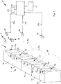
- Figure 1 shows a schematic perspective view of a refrigerated sales furniture 2 according to an exemplary embodiment of the invention.
- a refrigerated sales cabinet is shown as an example of a refrigerated sales furniture 2.
- the refrigerated sales furniture 2 typically comprises a plurality of refrigerated sales spaces 5a-5e, which are configured for storing products 20 to be presented therein.
- An access area 3 providing access to the refrigerated sales spaces 5a-5e is formed by the upright front portion located in front of the refrigerated sales spaces 5a-5e of the refrigerated sales furniture 2.
- a plurality of shelves or racks which are not shown in Figure 1 , may be provided within the refrigerated sales spaces 5a-5e for accommodating and supporting the products 20 to be stored.
- the invention may be applied to other types of refrigerated sales furnitures 2 as well, for example to refrigerated sales islands or refrigerated sales chests, in which the products 20 to be presented therein are stored on a bottom portion thereof and in which the access area providing access to the refrigerated sales space is formed by the upper horizontal portion of the refrigerated sales island or chest, which is located above the refrigerated sales space.
- the refrigerated sales furniture 2 shown in Figure 1 has a furniture body and comprises a plurality of compartments 4a-4e positioned adjacent to each other. Each of the plurality of compartments 4a-4e defines at least one refrigerated sales space 5a-5e.
- the refrigerated sales spaces 5a-5e may be equipped with a plurality of shelves or racks 10a, 10b, which are not shown in Figure 1 .
- the shelves 10a, 10b may be arranged on top of each other in the refrigerated sales space 5a-5e for receiving and supporting products 20, which are to be stored within the refrigerated sales furniture 2.
- Each of the compartments 4a-4e may be provided with at least one door 15a-15e, 17a-17e at the access area 3.
- the at least one door 15a-15e, 17a-17e may be at last partially transparent.
- the open access area 3 may provide free access to the products 20 provided in the respective refrigerated sales space 5a-5e, without doors.
- Figure 1 further depicts an embodiment of an identification device 13 which includes a plurality of cameras 6a, 6b, 6c directed onto the access areas 3 of the compartments 4a-4e for taking pictures of products 20 which are put into or taken out of the refrigerated sales spaces 5a-5e of the compartments 4a-4e.
- the cameras 6a, 6b, 6c of the identification device 13 may be mounted to the compartments 4a-4e, in particular to upper portions of the compartments 4a-4e.
- the cameras 6a, 6b, 6c may be mounted to the ceiling or to walls/pillars of a room housing the refrigerated sales furniture 2.
- Each of the cameras 6a, 6b, 6c has a corresponding image capturing area 8a, 8b, 8c covering a part of the front portion of the refrigerated sales furniture 2.
- Each image capturing area 8a, 8b, 8c is associated with one of the compartments 4a-4e.
- An image capturing area 8a, 8b, 8c also may encompass a plurality of compartments 4a-4e. Adjacent image capturing areas 8a, 8b, 8c may overlap, as it is illustrated in Figure 1 .
- the identification device 13 further comprises an identification unit 9 connected with the cameras 6a, 6b, 6c.
- the identification unit 9 is configured for evaluating the pictures provided by the cameras 6a, 6b, 6c for identifying products 20 passing the access area 3 of the compartments 4a-4e and determining which products 20 are put into and/or taken out of the refrigerated sales furniture 2.
- the connection between the cameras 6a, 6b, 6c and the identification unit 9 may be provided by cables 25a, 25b, 25c or by wireless data connections.
- the identification unit 9 is coupled with a tracking unit 21, which is configured for keeping track of the products 20 put into and/or taken out of the refrigerated sales furniture 2. This allows the tracking unit 21 to always provide up-to-date information about the products 20 being present within the the refrigerated sales spaces 5a-5e of the refrigerated sales furniture 2.
- the tracking unit 21 may be provided integrated with or separated from the identification unit 9.
- the identification unit 9 and the tracking unit 21 may be located in at least one of the compartments 4a-4e. Alternatively, the identification unit 9 and the tracking unit 21 may be provided in some distance from the refrigerated sales furniture 2, e.g. in a separate room (not shown). In an embodiment, one central identification unit 9, which is connected to all cameras 6a, 6b, 6c within a store may be provided. Similarly, a central tracking unit 21, which is connected to a central identification unit 9 or to a plurality of distributed identification units 9, may be provided.
- the cameras 6a, 6b, 6c may be connected to a remote identification unit 9, which is configured for evaluating the pictures provided from cameras 6a, 6b, 6c, which are located in a plurality of stores.
- the remote identification unit 9 may be integrated with or connected to a corresponding remote tracking unit 21. With such a configuration, the stock of a plurality of stores may be monitored employing only a single identification unit 9 and a single tracking unit 21.
- the cameras 6a, 6b, 6c and the identification unit 9 further may be configured for detecting whether the doors 15a-15e, 17a-17e are completely closed. This allows the identification unit 9, the tracking unit 21 or an additional door monitoring unit 23, which is connected with the identification unit 9, to issue an alarm signal in case at least one of the doors 15a-15e, 17a-17e is not completely closed for more than a predetermined period of time.
- the identification device 13 may further include at least one illumination device 7, which is configured for illuminating the access area 3 of the refrigerated sales furniture 2.
- the at least one illumination device 7 may provide white light comprising all colors of the spectrum in order to facilitate the identification of the products 20 based on their respective color(s).
- the at least one illumination device 7 may provide IR-light or UV-light, which may be reflected by corresponding labels 24 attached to at least some of the products 20.
- the illumination device 7 also may comprise a laser light source, which might be beneficial for detecting optical codes such as bar codes.
- the at least one illumination device 7 may be mounted to the compartments 4a-4e, in particular to a top portion of each of the compartments 4a-4e, or to the ceiling and/or to walls/pillars of the room housing the refrigerated sales furniture 2.
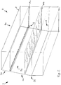
- Figure 2 depicts a schematic perspective view of a compartment 4a of a refrigerated sales furniture 2 according to an exemplary embodiment of the invention.
- the compartment 4a may be one of a plurality of adjacent compartments 4a-4e, as illustrated in Figure 1 , or it may be a single compartment 4a constituting a complete refrigerated sales furniture 2 on its own.
- the compartment 4a may comprise components of a refrigeration circuit, i.e. an evaporator, a compressor, a condenser and an expansion device, which are not shown in Figure 2 .
- the compressor and the condenser may also be located outside the compartment 4a, e.g. in a machine room or on the outside/on the roof of the building housing the refrigerated sales furniture 2, respectively.
- the compartment 4a is provided with a plurality of horizontally extending shelves 10a, 10b, which are arranged on top of each other.
- shelves 10a, 10b which are arranged on top of each other.
- other types of storage means e.g. inclined shelves, chests, trays etc. may be provided as well.
- cameras 6a, 6b, 6c and/or RFID readers 6d, 6e, 6f which are not visible in Figure 2 , are provided inside a product reader bar 12, which is provided at the front edge of an upper shelf 10a.
- cameras 6a, 6b, 6c, which are provided inside the product reader bar 12 are configured for taking pictures of products 20 passing an upright middle portion 3b of the access area 3 when being placed onto or taken from a lower shelf 10b, which is provided below the upper shelf 10a.
- RFID readers 6d, 6e, 6f are provided inside the product reader bar 12, and they are configured for receiving signals from RFID tags comprised in labels 24 which are attached to products 20 passing an upright middle portion 3b of the access area 3 when being placed onto or taken from a lower shelf 10b.
- the RFID readers 6d, 6e, 6f associated with the middle portion 3b of the access area 3 in particular are configured not to receive signals from RFID tags attached to products 20 passing the upper or lower portions 3a, 3c of the access area 3.
- An additional product reader bar 12 (not shown) comprising additional cameras 6a, 6b, 6c and/or RFID readers 6d, 6e, 6f may be provided at an upper ceiling 11 of the compartment 4a for detecting products 20 passing an upright upper portion 3a of the access area when being placed onto or taken from the upper shelf 10a.
- an additional reader bar 12 comprising cameras 6a, 6b, 6c and/or RFID readers 6d, 6e, 6f may be provided at the front edge of the lower shelf 10b for detecting products 20 passing an upright lower portion 3c of the access area 3 when being put into or taken from a bottom refrigerated sales space 19, which is provided below the lower shelf 10b at the bottom of the compartment 4a.
- the product reader bar 12 By providing the product reader bar 12 at the front edge of the shelves 10a, 10b or at the front edge of the ceiling 11, respectively, it is accomplished that all products 20 passing the access area 3 are reliably detected by at least one of the cameras 6a, 6b, 6c and/or RFID readers 6d, 6e, 6f when being placed onto or taken out of one of the shelves 10a, 10b or the lower refrigerated sales space 19, respectively. In consequence, no products 20 can be taken from or put into the refrigerated sales space 5a, 19 of the compartment 14a without being detected by the identification device 13.
- At least one illumination device 7 which is not visible in Figure 2 , may be additionally provided within or next to the product reader bar 12 for illuminating the products 20 when passing the access area 3.
- the at least one illumination device 7 may be activated based on the intensity of ambient light within the access area 3 and/or only when at least one product 20 is detected within the access area 3.
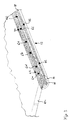
- Figure 3 shows an enlarged view of a product reader bar 12, as it is provided at the front edge of the upper shelf 10a shown in Figure 2 .
- the product reader bar 12 comprises a cap 14 formed by half of a tube which has been cut along its longitudinal direction.
- the cap 14 is attached to the lower side of the shelf 10a by means of an appropriate adhesive 18 providing a cavity extending along the front edge of the shelf 10a and being defined by the cap 14 and the shelf 10a.
- the lateral end sides of the cavity are closed by means of end plates 16 provided at each lateral end of the product reader bar 12.
- the cap 14 may be fixed to the shelf 10a by means of one or more mechanical fixtures 22, which are configured for fixing the cap 14 removably or permanently to the shelf 10a.
- the fixtures 22 in particular may include bolts, screws and clips.
- Cameras 6a, 6b, 6c and/or RFID readers 6d, 6e, 6f are provided inside the cavity formed by the cap 14 and the shelf 10a.
- At least one illumination device 7 (not shown in Figure 3 ), may be provided within said cavity, as well.
- the cap 14 is at least partially formed from a transparent material, e.g. plexi-glass.
- the cap 14 protects the at least one camera 6a, 6b, 6c, RFID readers 6d, 6e, 6f and/or the at least on illumination device 7 from adverse effects, in particular from being hit and damaged by products 20 placed into or taken out of the refrigerated sales furniture 2.
- the at least one identification device comprises at least one camera, which is configured for capturing pictures of products passing the at least one access area, and at least one identification unit, which is configured for identifying the products passing through the at least one access area from the pictures captured by the at least one camera, based on the optical properties of said products.
- the identification device is configured for identifying the products based on an optical code provided on the respective product.
- the code may be a usual barcode (e.g. one of the EAN, UPC, IAN and JAN codes), which already is provided on almost every product intended for sale.
- the code also may be an additional/new code, in particular a two-dimensional code, e.g. a QR-code, which is configured to be identified faster, more easily and/or more reliably than a barcode.
- An optical code allows a very reliable and unique identification of the products.
- the captured codes may be associated to reference codes stored for each product in one or more appropriate data bases.
- the identification of an optical code attached to the product also may be used for confirming a previous identification, which has been made based on the size/volume, the shape and/or the color of the product or its packing.
- the optical code may be printed directly onto the product or its packing. Alternatively, the optical code may be printed on a label, which is attached to the product or its packing.
- the identification device is configured as a barcode reader which is configured for identifying the products based on a barcode, which is attached to each of the products.
- the identification device is further configured for identifying additional information provided by the identified product or its packing.
- Said additional information in particular may include the production date and/or the best before date of the respective product. Identifying and keeping track of such information allows to optimize the stock-keeping even further.
- products may be taken out of the refrigerated sales furniture just before or at the best before date or after the best before date has passed and new products replacing said products may be ordered automatically or manually in due time.
- the cameras and the identification unit are configured for detecting whether the doors are completely closed. This allows the identification unit, the tracking unit or a special door monitoring unit to issue an alarm signal in case at least one of the doors is not completely closed for more than a predetermined period of time and helps to avoid that energy is wasted by operating the refrigerated sales furniture with the doors not being completely closed for a substantial period of time.
- the refrigerated sales furniture comprises at least one illumination device, which is configured for illuminating the products passing through the at least one access area.
- the illumination device in particular may provide white light comprising all colors of the spectrum in order to facilitate the identification of the products based on their respective color(s).
- the illumination device may provide IR-light and/or UV-light, which may be reflected by corresponding reflectors attached to at least some of the products.
- the at least one identification device comprises at least one RFID reader and at least one identification unit, which is connected with the at least one RFID reader.
- the products may be uniquely identified by means of RFID tags which are attached to the respective product. RFID tags allow a reliable and unique identification of the products.
- the at least one access area is an open access area providing free access to the refrigerated sales space.
- An open access area is very convenient for the costumers, as it does not require the costumers to open doors or flaps for accessing the products stored within the refrigerated sales space of the furniture.
- the refrigerated sales furniture comprises at least one door or flap, which allows for closing the access area.
- Providing a door or flap closing the access area reduces the energy needed for operating the refrigerated sales furniture, i.e. for cooling the refrigerated sales space, as warm air is prevented from entering into the refrigerated sales space and refrigerated air is prevented from flowing out of the refrigerated sales space when the at least one door or flap is closed.
- the at least one door or flap may be at least partially transparent for allowing customers to look into the refrigerated sales space without opening the at least one door or flap.
- the at least one identification device is configured to be activated when the at least one flap or door is opened, and to be deactivated when the at least one flap or door is closed.
- the at least one identification device is active only when the at least one door or flap has been opened for allowing products to be put into or taken out of the refrigerated sales space.
- the at least one identification device is deactivated, when the at least one door or flap is closed, the amount of energy consumed by the at least one identification device is reduced. Additionally, the risk of a false identification of products is minimized as well.
- the refrigerated sales space comprises at least one shelf or rack which is configured for receiving and supporting products to be stored. At least one camera and/or at least one RFID reader may be mounted to said at least one shelf. Installing at least one camera and/or at least one RFID reader at a shelf provided within the refrigerated sales space allows to identify the products put onto and taken from said shelf or an adjacent shelf, which is arranged above or below the shelf the camera and/or the RFID reader is attached to. Such a configuration in particular allows to identify products based on the shelf they are taken from. It further allows to provide more detailed product movement and product stock statistics, which in particular may include information related to the location of the products within the furniture.
- the refrigerated sales space is provided with a plurality of regions which are cooled to different temperatures, e.g. cooling temperatures above 0 °C and freezing temperatures below 0 °C, in particular below -10 °C.
- cooling temperatures above 0 °C and freezing temperatures below 0 °C, in particular below -10 °C are cooled to different temperatures.
- the refrigerated sales furniture is configured for determining the region or the shelf in/on which the product is placed, e.g. by determining the portion of the access area through which the product is passed.
- the refrigerated sales furniture is configured for triggering an alarm when a product is placed into a wrong temperature region or onto a wrong shelf within the refrigerated sales space. This helps to avoid products from being spoiled or damaged by being placed into a wrong area of the refrigerated sales space, in particular into an area, in which the temperatures are too high or too low for the respective product.
- At least one camera and/or at least one RFID reader is installed above at least one shelf and/or at least one camera and/or at least one RFID reader is installed at an edge of said shelf. Installing at least one camera and/or at least one RFID reader above and/or at the edge of the shelf allows the at least one identification device to reliably identify a product, which is put into and/or taken out of the refrigerated sales space.
- the at least one camera and/or at least one RFID reader is installed at a front portion of a shelf and being configured to identify products which are placed onto and/or are taken from said self.
- the detection area of the at least one camera and/or at least one RFID reader is facing basically upwards. This provides a very compact configuration, which allows to reliably identify a product, which is put onto and/or taken from such a shelf.
- pictures of all products may be stored in a storage device of the identification device.
- the identification device then may be configured for comparing current pictures of a product, which are provided by at least one of the cameras, with the previously stored pictures.
- the identification device in particular may be provided with a self-learning functionality, which allows adding additional pictures of new and/or previously known products to the previously stored pictures.
- the refrigerated sales furniture is configured for controlling the refrigeration based on the identified products, which have been put into the refrigerated sales space. This allows to operate the refrigerated sales furniture with high efficiency, as the actual (refrigerated) temperature is adjusted to the actual needs of the products stored within the refrigerated sales space. This securely avoids the products from being spoiled as a result from being stored at wrong, in particular too high, temperatures. It further avoids the refrigerated sales furniture from consuming too much energy by providing lower temperatures than needed for storing the respective products.
- the refrigerated sales furniture is configured for generating an order for new products based on the products which have been identified as having been taken out of the refrigerated sales space.
- new products for refilling the refrigerated sales furniture may be ordered automatically before the refrigerated sales furniture is completely empty.
- stock-keeping is facilitated, as it is not necessary to manually check the amount or number of products, which are still present within the refrigerated sales furniture, and to order new products as soon as the number or amount of products, which are still present within the refrigerated sales furniture, has reached a certain lower limit.
- the stock-keeping of refrigerated products may be considerably facilitated by employing a refrigerated sales furniture and/or a method of operating such a refrigerated sales furniture according to exemplary embodiments of the invention.
Landscapes
- Engineering & Computer Science (AREA)
- Chemical & Material Sciences (AREA)
- Combustion & Propulsion (AREA)
- Physics & Mathematics (AREA)
- Mechanical Engineering (AREA)
- Thermal Sciences (AREA)
- General Engineering & Computer Science (AREA)
- Management, Administration, Business Operations System, And Electronic Commerce (AREA)
- Cold Air Circulating Systems And Constructional Details In Refrigerators (AREA)
Claims (13)
- Gekühltes Verkaufsmöbel (2), umfassend:einen Möbelkorpus, der eine Vielzahl von Fächern (4a-4e) aufweist, wobei jedes der Fächer (4a-4e) mindestens einen gekühlten Verkaufsraum (5a-5e) zum Aufbewahren von Produkten, die darin präsentiert werden sollen, bereitstellt;mindestens einen Zugangsbereich (3), der Zugang zu dem gekühlten Verkaufsraum (5a-5e) bereitstellt; undmindestens eine Identifizierungsvorrichtung (13), die zum Identifizieren von Produkten (20), die den mindestens einen Zugangsbereich (3) passieren, angeordnet und konfiguriert ist;dadurch gekennzeichnet, dass die
Identifizierungsvorrichtung (13) zum Identifizieren der Produkte (20) auf Grundlage ihrer Größe / ihres Volumens und/oder ihrer Form und/oder Farbe konfiguriert ist, wobei die Identifizierungsvorrichtung (13) eine Vielzahl von Kameras (6a, 6b, 6c) umfasst, wobei jede der Kameras (6a, 6b, 6c) einen entsprechenden Bildaufnahmebereich (8a, 8b, 8c) aufweist, der einen Teil des vorderen Abschnitts des gekühlten Verkaufsmöbels (2) abdeckt, und jeder Bildaufnahmebereich (8a, 8b, 8c) mit je mindestens einem der Fächer (4a-4e) assoziiert ist und das gekühlte Verkaufsmöbel (2) konfiguriert ist, die Zonen des gekühlten Verkaufsraums (5a-5e), in denen die Produkte (20) platziert werden, durch Bestimmen des Abschnitts des Zugangsbereichs (3), den das jeweilige Produkt (20) passiert, zu bestimmen. - Gekühltes Verkaufsmöbel (2) nach Anspruch 1, ferner umfassend mindestens eine Beleuchtungsvorrichtung (7), insbesondere eine IR-Beleuchtungsvorrichtung (7), die zum Beleuchten der Produkte (20), die den mindestens einen Zugangsbereich (3) passieren, konfiguriert ist.
- Gekühltes Verkaufsmöbel (2) nach einem der vorhergehenden Ansprüche, wobei die mindestens eine Identifizierungsvorrichtung (13) mindestens einen RFID-Leser (6d, 6e, 6f) umfasst.
- Gekühltes Verkaufsmöbel (2) nach einem der vorhergehenden Ansprüche, umfassend mindestens eine Klappe oder Tür (15a-15e, 17a-17e), die es ermöglicht, den Zugangsbereich (3) zu verschließen, wobei die mindestens eine Identifizierungsvorrichtung (13) insbesondere dazu konfiguriert ist, nur aktiviert zu werden, wenn die mindestens eine Klappe oder Tür (15a-15e, 17a-17e) geöffnet wird.
- Gekühltes Verkaufsmöbel (2) nach einem der vorhergehenden Ansprüche, wobei die mindestens eine Identifizierungsvorrichtung (13) ferner zum Identifizieren zusätzlicher Informationen über die Produkte (20) konfiguriert ist, zu denen insbesondere das Herstellungsdatum und/oder das Mindesthaltbarkeitsdatum des identifizierten Produkts (20) gehört/gehören.
- Gekühltes Verkaufsmöbel (2) nach einem der vorhergehenden Ansprüche, wobei der gekühlte Verkaufsraum (5a-5e) einen Regalboden (10a, 10b) zum Aufnehmen und Halten der aufzubewahrenden Produkte (20) umfasst und wobei mindestens eine Kamera (6a, 6b, 6c) und/oder mindestens ein RFID-Leser (6d, 6e, 6f) an dem mindestens einen Regalboden (10a, 10b) installiert ist.
- Gekühltes Verkaufsmöbel (2) nach Anspruch 6, wobei mindestens eine Kamera (6a, 6b, 6c) oder mindestens ein RFID-Leser (6d, 6e, 6f) über dem mindestens einen Regalboden (10a, 10b) installiert ist oder wobei die mindestens eine Kamera (6a, 6b, 6c) oder der mindestens eine RFID-Leser (6d, 6e, 6f) an einer Vorderkante des mindestens einen Regalbodens (10a, 10b) installiert ist.
- Gekühltes Verkaufsmöbel (2) nach einem der vorhergehenden Ansprüche, das konfiguriert ist, die Kühlung auf Grundlage der identifizierten Produkte (20) zu steuern.
- Gekühltes Verkaufsmöbel (2) nach einem der vorhergehenden Ansprüche, das konfiguriert ist, einen Alarm auszulösen, wenn ein Produkt (20) in einem falschen Bereich des gekühlten Verkaufsraums (5a-5e) platziert wird.
- Gekühltes Verkaufsmöbel (2) nach einem der vorhergehenden Ansprüche, das konfiguriert ist, auf Grundlage der identifizierten Produkte (20) eine Bestellung neuer Produkte (20) zu erzeugen.
- Verfahren zum Betreiben eines gekühlten Verkaufsmöbels (2), wobei das gekühlte Verkaufsmöbel (2) umfasst:einen Möbelkorpus, der eine Vielzahl von Fächern (4a-4e) aufweist, wobei jedes der Fächer (4a-4e) mindestens einen gekühlten Verkaufsraum (5a-5e) zum Aufbewahren von Produkten, die darin präsentiert werden sollen, bereitstellt;mindestens einen Zugangsbereich (3), der Zugang zu dem gekühlten Verkaufsraum (5a-5e) bereitstellt; undmindestens eine Identifizierungsvorrichtung (13), die zum Identifizieren von Produkten (20), die den mindestens einen Zugangsbereich (3) passieren, angeordnet und konfiguriert ist;wobei die Identifizierungsvorrichtung (13) eine Vielzahl von Kameras (6a, 6b, 6c) umfasst, wobei jede der Kameras (6a, 6b, 6c) einen entsprechenden Bildaufnahmebereich (8a, 8b, 8c) aufweist, der einen Teil des vorderen Abschnitts des gekühlten Möbels (2) abdeckt, und wobei jeder Bildaufnahmebereich (8a, 8b, 8c) mit je mindestens einem der Fächer (4a-4e) assoziiert ist, wobei die Identifizierungsvorrichtung (13) zum Identifizieren der Produkte (20) auf Grundlage ihrer Größe / ihres Volumens, ihrer Form und/oder Farbe konfiguriert ist; undwobei das Verfahren den Schritt umfasst, Produkte (20) zu identifizieren, die den mindestens einen Zugangsbereich (3) passieren, und durch Bestimmen des Abschnitts des Zugangsbereichs (3), den das jeweilige Produkt (20) passiert, die Zonen des gekühlten Verkaufsraums (5a-5e) zu bestimmen, in denen die Produkte (20) platziert werden.
- Verfahren nach Anspruch 11, ferner umfassend den Schritt des Steuerns der Kühlung des gekühlten Verkaufsmöbels (2) auf Grundlage der Produkte (20), die durch die mindestens eine Identifizierungsvorrichtung (13) identifiziert wurden.
- Verfahren nach Anspruch 11 oder 12, ferner umfassend den Schritt des Bestellens neuer Produkte (20) auf Grundlage der Produkte (20), die als aus dem gekühlten Verkaufsraum (5a-5e) entnommen identifiziert worden sind.
Applications Claiming Priority (1)
| Application Number | Priority Date | Filing Date | Title |
|---|---|---|---|
| PCT/EP2015/076313 WO2017080595A1 (en) | 2015-11-11 | 2015-11-11 | Refrigerated sales furniture |
Publications (2)
| Publication Number | Publication Date |
|---|---|
| EP3374711A1 EP3374711A1 (de) | 2018-09-19 |
| EP3374711B1 true EP3374711B1 (de) | 2021-04-07 |
Family
ID=54540086
Family Applications (1)
| Application Number | Title | Priority Date | Filing Date |
|---|---|---|---|
| EP15793813.5A Active EP3374711B1 (de) | 2015-11-11 | 2015-11-11 | Gekühltes verkaufsmöbelstück |
Country Status (3)
| Country | Link |
|---|---|
| EP (1) | EP3374711B1 (de) |
| CN (1) | CN108351160A (de) |
| WO (1) | WO2017080595A1 (de) |
Citations (3)
| Publication number | Priority date | Publication date | Assignee | Title |
|---|---|---|---|---|
| JPH109753A (ja) * | 1996-06-26 | 1998-01-16 | Matsushita Refrig Co Ltd | 冷凍冷蔵庫の食品在庫管理装置 |
| JP2012112646A (ja) * | 2008-04-03 | 2012-06-14 | Mitsubishi Electric Corp | 収納庫及び冷蔵庫 |
| WO2014168265A1 (ko) * | 2013-04-10 | 2014-10-16 | 엘지전자 주식회사 | 영상 인식을 이용한 냉장고의 보관 품목 관리 방법 및 그 냉장고 |
Family Cites Families (6)
| Publication number | Priority date | Publication date | Assignee | Title |
|---|---|---|---|---|
| JP2001183051A (ja) * | 1999-12-27 | 2001-07-06 | Fuji Electric Co Ltd | 店舗管理システム、商品状態管理方法およびその方法をコンピュータに実行させるプログラムを記録したコンピュータ読み取り可能な記録媒体 |
| US8757434B2 (en) * | 2010-07-01 | 2014-06-24 | The Coca-Cola Company | Merchandiser |
| US9384458B2 (en) * | 2011-10-13 | 2016-07-05 | Thermo King Corporation | Auto configuration of refrigeration systems in cold chain |
| WO2014031976A1 (en) * | 2012-08-23 | 2014-02-27 | Medchain Systems, Inc. | Smart storage of temperature sensitive pharmaceuticals |
| JP6229142B2 (ja) * | 2013-03-29 | 2017-11-15 | パナソニックIpマネジメント株式会社 | 冷蔵庫及び冷蔵庫システム |
| CN104482711B (zh) * | 2014-12-10 | 2017-06-23 | 四川长虹电器股份有限公司 | 冰箱智能控制系统及其方法 |
-
2015
- 2015-11-11 EP EP15793813.5A patent/EP3374711B1/de active Active
- 2015-11-11 CN CN201580084490.0A patent/CN108351160A/zh active Pending
- 2015-11-11 WO PCT/EP2015/076313 patent/WO2017080595A1/en not_active Ceased
Patent Citations (4)
| Publication number | Priority date | Publication date | Assignee | Title |
|---|---|---|---|---|
| JPH109753A (ja) * | 1996-06-26 | 1998-01-16 | Matsushita Refrig Co Ltd | 冷凍冷蔵庫の食品在庫管理装置 |
| JP2012112646A (ja) * | 2008-04-03 | 2012-06-14 | Mitsubishi Electric Corp | 収納庫及び冷蔵庫 |
| WO2014168265A1 (ko) * | 2013-04-10 | 2014-10-16 | 엘지전자 주식회사 | 영상 인식을 이용한 냉장고의 보관 품목 관리 방법 및 그 냉장고 |
| US20160088262A1 (en) * | 2013-04-10 | 2016-03-24 | Lg Electronics Inc. | Method For Managing Storage Product In Refrigerator Using Image Recognition, And Refrigerator For Same |
Also Published As
| Publication number | Publication date |
|---|---|
| WO2017080595A1 (en) | 2017-05-18 |
| EP3374711A1 (de) | 2018-09-19 |
| CN108351160A (zh) | 2018-07-31 |
Similar Documents
| Publication | Publication Date | Title |
|---|---|---|
| US7737855B2 (en) | Apparatus and system for stock control | |
| US20080103939A1 (en) | Computerized-Sensing System For A Mini Bar | |
| US9412086B2 (en) | Apparatus and method for customized product data management | |
| CN104820811B (zh) | 用于识别货架占用情况的rfid读取装置 | |
| RU2701395C2 (ru) | Устройство для выдачи продукта (варианты) | |
| RU2523617C2 (ru) | Видеодисплей для витрин с продуктами | |
| US20160138859A1 (en) | Refrigeration appliance system | |
| US20160138857A1 (en) | Refrigeration appliance comprising a camera module | |
| SE522000C2 (sv) | Förfarande och anordning för att hålla reda på lagringstiden för i ett utrymme förvarade varor | |
| US20090303018A1 (en) | Electronic label provided with means for reading and displaying rfid chip content | |
| BR112014004161B1 (pt) | sistema de prateleira para exibir itens removíveis, montagem de prateleira composta, método de estabelecimento e manutenção eletrônicos, dispensador de prateleira e sistema de prateleira. | |
| JP7137369B2 (ja) | 冷蔵庫 | |
| TW200511135A (en) | Merchandise management system and merchandise management program | |
| KR20190090290A (ko) | 인공지능을 이용하여 제품을 식별하고 구분된 이미지를 출력하는 냉장고 및 방법 | |
| EP3374711B1 (de) | Gekühltes verkaufsmöbelstück | |
| CN100334988C (zh) | 陈列柜 | |
| EP4116648B1 (de) | Arzneimittelaufbewahrungsbox | |
| KR20130003607A (ko) | 냉장고 내의 식품정보 표시장치 | |
| JP7261607B2 (ja) | ショーケース | |
| KR102179630B1 (ko) | 자판기 | |
| KR100625491B1 (ko) | 냉장고의 음식물 위치 알림장치 | |
| JP2010073152A (ja) | 自動販売機の商品管理装置 | |
| US20240098355A1 (en) | Camera system to monitor goods in cabinet | |
| RU2820492C1 (ru) | Автоматизированный шкаф для продуктов с функцией учета запасов | |
| KR100621199B1 (ko) | 냉장고 |
Legal Events
| Date | Code | Title | Description |
|---|---|---|---|
| STAA | Information on the status of an ep patent application or granted ep patent |
Free format text: STATUS: THE INTERNATIONAL PUBLICATION HAS BEEN MADE |
|
| PUAI | Public reference made under article 153(3) epc to a published international application that has entered the european phase |
Free format text: ORIGINAL CODE: 0009012 |
|
| STAA | Information on the status of an ep patent application or granted ep patent |
Free format text: STATUS: REQUEST FOR EXAMINATION WAS MADE |
|
| 17P | Request for examination filed |
Effective date: 20180419 |
|
| AK | Designated contracting states |
Kind code of ref document: A1 Designated state(s): AL AT BE BG CH CY CZ DE DK EE ES FI FR GB GR HR HU IE IS IT LI LT LU LV MC MK MT NL NO PL PT RO RS SE SI SK SM TR |
|
| AX | Request for extension of the european patent |
Extension state: BA ME |
|
| DAV | Request for validation of the european patent (deleted) | ||
| DAX | Request for extension of the european patent (deleted) | ||
| STAA | Information on the status of an ep patent application or granted ep patent |
Free format text: STATUS: EXAMINATION IS IN PROGRESS |
|
| 17Q | First examination report despatched |
Effective date: 20190404 |
|
| GRAP | Despatch of communication of intention to grant a patent |
Free format text: ORIGINAL CODE: EPIDOSNIGR1 |
|
| STAA | Information on the status of an ep patent application or granted ep patent |
Free format text: STATUS: GRANT OF PATENT IS INTENDED |
|
| INTG | Intention to grant announced |
Effective date: 20201029 |
|
| GRAS | Grant fee paid |
Free format text: ORIGINAL CODE: EPIDOSNIGR3 |
|
| GRAA | (expected) grant |
Free format text: ORIGINAL CODE: 0009210 |
|
| STAA | Information on the status of an ep patent application or granted ep patent |
Free format text: STATUS: THE PATENT HAS BEEN GRANTED |
|
| AK | Designated contracting states |
Kind code of ref document: B1 Designated state(s): AL AT BE BG CH CY CZ DE DK EE ES FI FR GB GR HR HU IE IS IT LI LT LU LV MC MK MT NL NO PL PT RO RS SE SI SK SM TR |
|
| REG | Reference to a national code |
Ref country code: GB Ref legal event code: FG4D |
|
| RIN1 | Information on inventor provided before grant (corrected) |
Inventor name: COLDRE, LAURENT |
|
| REG | Reference to a national code |
Ref country code: CH Ref legal event code: EP Ref country code: AT Ref legal event code: REF Ref document number: 1380221 Country of ref document: AT Kind code of ref document: T Effective date: 20210415 |
|
| REG | Reference to a national code |
Ref country code: DE Ref legal event code: R096 Ref document number: 602015067835 Country of ref document: DE |
|
| REG | Reference to a national code |
Ref country code: IE Ref legal event code: FG4D |
|
| REG | Reference to a national code |
Ref country code: NL Ref legal event code: FP |
|
| REG | Reference to a national code |
Ref country code: LT Ref legal event code: MG9D |
|
| REG | Reference to a national code |
Ref country code: AT Ref legal event code: MK05 Ref document number: 1380221 Country of ref document: AT Kind code of ref document: T Effective date: 20210407 |
|
| PG25 | Lapsed in a contracting state [announced via postgrant information from national office to epo] |
Ref country code: FI Free format text: LAPSE BECAUSE OF FAILURE TO SUBMIT A TRANSLATION OF THE DESCRIPTION OR TO PAY THE FEE WITHIN THE PRESCRIBED TIME-LIMIT Effective date: 20210407 Ref country code: LT Free format text: LAPSE BECAUSE OF FAILURE TO SUBMIT A TRANSLATION OF THE DESCRIPTION OR TO PAY THE FEE WITHIN THE PRESCRIBED TIME-LIMIT Effective date: 20210407 Ref country code: AT Free format text: LAPSE BECAUSE OF FAILURE TO SUBMIT A TRANSLATION OF THE DESCRIPTION OR TO PAY THE FEE WITHIN THE PRESCRIBED TIME-LIMIT Effective date: 20210407 Ref country code: BG Free format text: LAPSE BECAUSE OF FAILURE TO SUBMIT A TRANSLATION OF THE DESCRIPTION OR TO PAY THE FEE WITHIN THE PRESCRIBED TIME-LIMIT Effective date: 20210707 Ref country code: HR Free format text: LAPSE BECAUSE OF FAILURE TO SUBMIT A TRANSLATION OF THE DESCRIPTION OR TO PAY THE FEE WITHIN THE PRESCRIBED TIME-LIMIT Effective date: 20210407 |
|
| PG25 | Lapsed in a contracting state [announced via postgrant information from national office to epo] |
Ref country code: IS Free format text: LAPSE BECAUSE OF FAILURE TO SUBMIT A TRANSLATION OF THE DESCRIPTION OR TO PAY THE FEE WITHIN THE PRESCRIBED TIME-LIMIT Effective date: 20210807 Ref country code: GR Free format text: LAPSE BECAUSE OF FAILURE TO SUBMIT A TRANSLATION OF THE DESCRIPTION OR TO PAY THE FEE WITHIN THE PRESCRIBED TIME-LIMIT Effective date: 20210708 Ref country code: LV Free format text: LAPSE BECAUSE OF FAILURE TO SUBMIT A TRANSLATION OF THE DESCRIPTION OR TO PAY THE FEE WITHIN THE PRESCRIBED TIME-LIMIT Effective date: 20210407 Ref country code: RS Free format text: LAPSE BECAUSE OF FAILURE TO SUBMIT A TRANSLATION OF THE DESCRIPTION OR TO PAY THE FEE WITHIN THE PRESCRIBED TIME-LIMIT Effective date: 20210407 Ref country code: SE Free format text: LAPSE BECAUSE OF FAILURE TO SUBMIT A TRANSLATION OF THE DESCRIPTION OR TO PAY THE FEE WITHIN THE PRESCRIBED TIME-LIMIT Effective date: 20210407 Ref country code: PT Free format text: LAPSE BECAUSE OF FAILURE TO SUBMIT A TRANSLATION OF THE DESCRIPTION OR TO PAY THE FEE WITHIN THE PRESCRIBED TIME-LIMIT Effective date: 20210809 Ref country code: NO Free format text: LAPSE BECAUSE OF FAILURE TO SUBMIT A TRANSLATION OF THE DESCRIPTION OR TO PAY THE FEE WITHIN THE PRESCRIBED TIME-LIMIT Effective date: 20210707 Ref country code: PL Free format text: LAPSE BECAUSE OF FAILURE TO SUBMIT A TRANSLATION OF THE DESCRIPTION OR TO PAY THE FEE WITHIN THE PRESCRIBED TIME-LIMIT Effective date: 20210407 |
|
| REG | Reference to a national code |
Ref country code: DE Ref legal event code: R097 Ref document number: 602015067835 Country of ref document: DE |
|
| PG25 | Lapsed in a contracting state [announced via postgrant information from national office to epo] |
Ref country code: RO Free format text: LAPSE BECAUSE OF FAILURE TO SUBMIT A TRANSLATION OF THE DESCRIPTION OR TO PAY THE FEE WITHIN THE PRESCRIBED TIME-LIMIT Effective date: 20210407 Ref country code: ES Free format text: LAPSE BECAUSE OF FAILURE TO SUBMIT A TRANSLATION OF THE DESCRIPTION OR TO PAY THE FEE WITHIN THE PRESCRIBED TIME-LIMIT Effective date: 20210407 Ref country code: SM Free format text: LAPSE BECAUSE OF FAILURE TO SUBMIT A TRANSLATION OF THE DESCRIPTION OR TO PAY THE FEE WITHIN THE PRESCRIBED TIME-LIMIT Effective date: 20210407 Ref country code: SK Free format text: LAPSE BECAUSE OF FAILURE TO SUBMIT A TRANSLATION OF THE DESCRIPTION OR TO PAY THE FEE WITHIN THE PRESCRIBED TIME-LIMIT Effective date: 20210407 Ref country code: CZ Free format text: LAPSE BECAUSE OF FAILURE TO SUBMIT A TRANSLATION OF THE DESCRIPTION OR TO PAY THE FEE WITHIN THE PRESCRIBED TIME-LIMIT Effective date: 20210407 Ref country code: DK Free format text: LAPSE BECAUSE OF FAILURE TO SUBMIT A TRANSLATION OF THE DESCRIPTION OR TO PAY THE FEE WITHIN THE PRESCRIBED TIME-LIMIT Effective date: 20210407 Ref country code: EE Free format text: LAPSE BECAUSE OF FAILURE TO SUBMIT A TRANSLATION OF THE DESCRIPTION OR TO PAY THE FEE WITHIN THE PRESCRIBED TIME-LIMIT Effective date: 20210407 |
|
| PLBE | No opposition filed within time limit |
Free format text: ORIGINAL CODE: 0009261 |
|
| STAA | Information on the status of an ep patent application or granted ep patent |
Free format text: STATUS: NO OPPOSITION FILED WITHIN TIME LIMIT |
|
| 26N | No opposition filed |
Effective date: 20220110 |
|
| PG25 | Lapsed in a contracting state [announced via postgrant information from national office to epo] |
Ref country code: IS Free format text: LAPSE BECAUSE OF FAILURE TO SUBMIT A TRANSLATION OF THE DESCRIPTION OR TO PAY THE FEE WITHIN THE PRESCRIBED TIME-LIMIT Effective date: 20210807 Ref country code: AL Free format text: LAPSE BECAUSE OF FAILURE TO SUBMIT A TRANSLATION OF THE DESCRIPTION OR TO PAY THE FEE WITHIN THE PRESCRIBED TIME-LIMIT Effective date: 20210407 |
|
| PG25 | Lapsed in a contracting state [announced via postgrant information from national office to epo] |
Ref country code: MC Free format text: LAPSE BECAUSE OF FAILURE TO SUBMIT A TRANSLATION OF THE DESCRIPTION OR TO PAY THE FEE WITHIN THE PRESCRIBED TIME-LIMIT Effective date: 20210407 |
|
| REG | Reference to a national code |
Ref country code: CH Ref legal event code: PL |
|
| PG25 | Lapsed in a contracting state [announced via postgrant information from national office to epo] |
Ref country code: LU Free format text: LAPSE BECAUSE OF NON-PAYMENT OF DUE FEES Effective date: 20211111 Ref country code: BE Free format text: LAPSE BECAUSE OF NON-PAYMENT OF DUE FEES Effective date: 20211130 |
|
| REG | Reference to a national code |
Ref country code: BE Ref legal event code: MM Effective date: 20211130 |
|
| PG25 | Lapsed in a contracting state [announced via postgrant information from national office to epo] |
Ref country code: IE Free format text: LAPSE BECAUSE OF NON-PAYMENT OF DUE FEES Effective date: 20211111 |
|
| PG25 | Lapsed in a contracting state [announced via postgrant information from national office to epo] |
Ref country code: HU Free format text: LAPSE BECAUSE OF FAILURE TO SUBMIT A TRANSLATION OF THE DESCRIPTION OR TO PAY THE FEE WITHIN THE PRESCRIBED TIME-LIMIT; INVALID AB INITIO Effective date: 20151111 |
|
| PG25 | Lapsed in a contracting state [announced via postgrant information from national office to epo] |
Ref country code: CY Free format text: LAPSE BECAUSE OF FAILURE TO SUBMIT A TRANSLATION OF THE DESCRIPTION OR TO PAY THE FEE WITHIN THE PRESCRIBED TIME-LIMIT Effective date: 20210407 |
|
| PG25 | Lapsed in a contracting state [announced via postgrant information from national office to epo] |
Ref country code: LI Free format text: LAPSE BECAUSE OF NON-PAYMENT OF DUE FEES Effective date: 20220701 Ref country code: CH Free format text: LAPSE BECAUSE OF NON-PAYMENT OF DUE FEES Effective date: 20220701 |
|
| PG25 | Lapsed in a contracting state [announced via postgrant information from national office to epo] |
Ref country code: MK Free format text: LAPSE BECAUSE OF FAILURE TO SUBMIT A TRANSLATION OF THE DESCRIPTION OR TO PAY THE FEE WITHIN THE PRESCRIBED TIME-LIMIT Effective date: 20210407 |
|
| PG25 | Lapsed in a contracting state [announced via postgrant information from national office to epo] |
Ref country code: MT Free format text: LAPSE BECAUSE OF FAILURE TO SUBMIT A TRANSLATION OF THE DESCRIPTION OR TO PAY THE FEE WITHIN THE PRESCRIBED TIME-LIMIT Effective date: 20210407 |
|
| PGFP | Annual fee paid to national office [announced via postgrant information from national office to epo] |
Ref country code: DE Payment date: 20241022 Year of fee payment: 10 |
|
| PG25 | Lapsed in a contracting state [announced via postgrant information from national office to epo] |
Ref country code: TR Free format text: LAPSE BECAUSE OF FAILURE TO SUBMIT A TRANSLATION OF THE DESCRIPTION OR TO PAY THE FEE WITHIN THE PRESCRIBED TIME-LIMIT Effective date: 20210407 |
|
| PGFP | Annual fee paid to national office [announced via postgrant information from national office to epo] |
Ref country code: NL Payment date: 20251119 Year of fee payment: 11 |
|
| PGFP | Annual fee paid to national office [announced via postgrant information from national office to epo] |
Ref country code: GB Payment date: 20251119 Year of fee payment: 11 |
|
| PGFP | Annual fee paid to national office [announced via postgrant information from national office to epo] |
Ref country code: IT Payment date: 20251121 Year of fee payment: 11 |
|
| PGFP | Annual fee paid to national office [announced via postgrant information from national office to epo] |
Ref country code: FR Payment date: 20251120 Year of fee payment: 11 |