EP3374128B1 - Procédé et système pour usinage, et système robotique - Google Patents
Procédé et système pour usinage, et système robotique Download PDFInfo
- Publication number
- EP3374128B1 EP3374128B1 EP15908022.5A EP15908022A EP3374128B1 EP 3374128 B1 EP3374128 B1 EP 3374128B1 EP 15908022 A EP15908022 A EP 15908022A EP 3374128 B1 EP3374128 B1 EP 3374128B1
- Authority
- EP
- European Patent Office
- Prior art keywords
- actual
- default
- machining
- machining tool
- contact point
- Prior art date
- Legal status (The legal status is an assumption and is not a legal conclusion. Google has not performed a legal analysis and makes no representation as to the accuracy of the status listed.)
- Active
Links
- 238000003754 machining Methods 0.000 title claims description 162
- 238000000034 method Methods 0.000 title claims description 17
- 238000010586 diagram Methods 0.000 description 6
- 230000008901 benefit Effects 0.000 description 3
- 238000012986 modification Methods 0.000 description 3
- 230000004048 modification Effects 0.000 description 3
- 230000003044 adaptive effect Effects 0.000 description 2
- 229910052705 radium Inorganic materials 0.000 description 2
- HCWPIIXVSYCSAN-UHFFFAOYSA-N radium atom Chemical compound [Ra] HCWPIIXVSYCSAN-UHFFFAOYSA-N 0.000 description 2
- 230000006978 adaptation Effects 0.000 description 1
- 238000004364 calculation method Methods 0.000 description 1
- 238000004590 computer program Methods 0.000 description 1
Images


Classifications
-
- B—PERFORMING OPERATIONS; TRANSPORTING
- B24—GRINDING; POLISHING
- B24B—MACHINES, DEVICES, OR PROCESSES FOR GRINDING OR POLISHING; DRESSING OR CONDITIONING OF ABRADING SURFACES; FEEDING OF GRINDING, POLISHING, OR LAPPING AGENTS
- B24B51/00—Arrangements for automatic control of a series of individual steps in grinding a workpiece
-
- B—PERFORMING OPERATIONS; TRANSPORTING
- B24—GRINDING; POLISHING
- B24B—MACHINES, DEVICES, OR PROCESSES FOR GRINDING OR POLISHING; DRESSING OR CONDITIONING OF ABRADING SURFACES; FEEDING OF GRINDING, POLISHING, OR LAPPING AGENTS
- B24B27/00—Other grinding machines or devices
- B24B27/0038—Other grinding machines or devices with the grinding tool mounted at the end of a set of bars
-
- B—PERFORMING OPERATIONS; TRANSPORTING
- B24—GRINDING; POLISHING
- B24B—MACHINES, DEVICES, OR PROCESSES FOR GRINDING OR POLISHING; DRESSING OR CONDITIONING OF ABRADING SURFACES; FEEDING OF GRINDING, POLISHING, OR LAPPING AGENTS
- B24B9/00—Machines or devices designed for grinding edges or bevels on work or for removing burrs; Accessories therefor
-
- B—PERFORMING OPERATIONS; TRANSPORTING
- B25—HAND TOOLS; PORTABLE POWER-DRIVEN TOOLS; MANIPULATORS
- B25J—MANIPULATORS; CHAMBERS PROVIDED WITH MANIPULATION DEVICES
- B25J9/00—Programme-controlled manipulators
- B25J9/16—Programme controls
- B25J9/1656—Programme controls characterised by programming, planning systems for manipulators
- B25J9/1664—Programme controls characterised by programming, planning systems for manipulators characterised by motion, path, trajectory planning
- B25J9/1666—Avoiding collision or forbidden zones
-
- G—PHYSICS
- G05—CONTROLLING; REGULATING
- G05B—CONTROL OR REGULATING SYSTEMS IN GENERAL; FUNCTIONAL ELEMENTS OF SUCH SYSTEMS; MONITORING OR TESTING ARRANGEMENTS FOR SUCH SYSTEMS OR ELEMENTS
- G05B19/00—Programme-control systems
- G05B19/02—Programme-control systems electric
- G05B19/18—Numerical control [NC], i.e. automatically operating machines, in particular machine tools, e.g. in a manufacturing environment, so as to execute positioning, movement or co-ordinated operations by means of programme data in numerical form
- G05B19/4093—Numerical control [NC], i.e. automatically operating machines, in particular machine tools, e.g. in a manufacturing environment, so as to execute positioning, movement or co-ordinated operations by means of programme data in numerical form characterised by part programming, e.g. entry of geometrical information as taken from a technical drawing, combining this with machining and material information to obtain control information, named part programme, for the NC machine
-
- G—PHYSICS
- G05—CONTROLLING; REGULATING
- G05B—CONTROL OR REGULATING SYSTEMS IN GENERAL; FUNCTIONAL ELEMENTS OF SUCH SYSTEMS; MONITORING OR TESTING ARRANGEMENTS FOR SUCH SYSTEMS OR ELEMENTS
- G05B19/00—Programme-control systems
- G05B19/02—Programme-control systems electric
- G05B19/18—Numerical control [NC], i.e. automatically operating machines, in particular machine tools, e.g. in a manufacturing environment, so as to execute positioning, movement or co-ordinated operations by means of programme data in numerical form
- G05B19/416—Numerical control [NC], i.e. automatically operating machines, in particular machine tools, e.g. in a manufacturing environment, so as to execute positioning, movement or co-ordinated operations by means of programme data in numerical form characterised by control of velocity, acceleration or deceleration
- G05B19/4163—Adaptive control of feed or cutting velocity
-
- G—PHYSICS
- G05—CONTROLLING; REGULATING
- G05B—CONTROL OR REGULATING SYSTEMS IN GENERAL; FUNCTIONAL ELEMENTS OF SUCH SYSTEMS; MONITORING OR TESTING ARRANGEMENTS FOR SUCH SYSTEMS OR ELEMENTS
- G05B2219/00—Program-control systems
- G05B2219/30—Nc systems
- G05B2219/35—Nc in input of data, input till input file format
- G05B2219/35158—Calculation of contact point of tool on surface, curve
-
- G—PHYSICS
- G05—CONTROLLING; REGULATING
- G05B—CONTROL OR REGULATING SYSTEMS IN GENERAL; FUNCTIONAL ELEMENTS OF SUCH SYSTEMS; MONITORING OR TESTING ARRANGEMENTS FOR SUCH SYSTEMS OR ELEMENTS
- G05B2219/00—Program-control systems
- G05B2219/30—Nc systems
- G05B2219/43—Speed, acceleration, deceleration control ADC
- G05B2219/43031—Feed speed reduction dependent on tool surface
-
- G—PHYSICS
- G05—CONTROLLING; REGULATING
- G05B—CONTROL OR REGULATING SYSTEMS IN GENERAL; FUNCTIONAL ELEMENTS OF SUCH SYSTEMS; MONITORING OR TESTING ARRANGEMENTS FOR SUCH SYSTEMS OR ELEMENTS
- G05B2219/00—Program-control systems
- G05B2219/30—Nc systems
- G05B2219/49—Nc machine tool, till multiple
- G05B2219/49077—Control of feed and spindle, cutting speed
-
- G—PHYSICS
- G05—CONTROLLING; REGULATING
- G05B—CONTROL OR REGULATING SYSTEMS IN GENERAL; FUNCTIONAL ELEMENTS OF SUCH SYSTEMS; MONITORING OR TESTING ARRANGEMENTS FOR SUCH SYSTEMS OR ELEMENTS
- G05B2219/00—Program-control systems
- G05B2219/30—Nc systems
- G05B2219/49—Nc machine tool, till multiple
- G05B2219/49088—As a function of, regulate feed as function of material, tool
-
- G—PHYSICS
- G05—CONTROLLING; REGULATING
- G05B—CONTROL OR REGULATING SYSTEMS IN GENERAL; FUNCTIONAL ELEMENTS OF SUCH SYSTEMS; MONITORING OR TESTING ARRANGEMENTS FOR SUCH SYSTEMS OR ELEMENTS
- G05B2219/00—Program-control systems
- G05B2219/30—Nc systems
- G05B2219/49—Nc machine tool, till multiple
- G05B2219/49103—Speed and feed
-
- G—PHYSICS
- G05—CONTROLLING; REGULATING
- G05B—CONTROL OR REGULATING SYSTEMS IN GENERAL; FUNCTIONAL ELEMENTS OF SUCH SYSTEMS; MONITORING OR TESTING ARRANGEMENTS FOR SUCH SYSTEMS OR ELEMENTS
- G05B2219/00—Program-control systems
- G05B2219/30—Nc systems
- G05B2219/49—Nc machine tool, till multiple
- G05B2219/49149—Ball end cutter interference, caused by tool shape, overcut part surface
-
- G—PHYSICS
- G05—CONTROLLING; REGULATING
- G05B—CONTROL OR REGULATING SYSTEMS IN GENERAL; FUNCTIONAL ELEMENTS OF SUCH SYSTEMS; MONITORING OR TESTING ARRANGEMENTS FOR SUCH SYSTEMS OR ELEMENTS
- G05B2219/00—Program-control systems
- G05B2219/30—Nc systems
- G05B2219/49—Nc machine tool, till multiple
- G05B2219/49157—Limitation, collision, interference, forbidden zones, avoid obstacles
-
- G—PHYSICS
- G05—CONTROLLING; REGULATING
- G05B—CONTROL OR REGULATING SYSTEMS IN GENERAL; FUNCTIONAL ELEMENTS OF SUCH SYSTEMS; MONITORING OR TESTING ARRANGEMENTS FOR SUCH SYSTEMS OR ELEMENTS
- G05B2219/00—Program-control systems
- G05B2219/30—Nc systems
- G05B2219/50—Machine tool, machine tool null till machine tool work handling
- G05B2219/50285—Tool geometry compensation, keep contact of tool on desired curve
-
- G—PHYSICS
- G05—CONTROLLING; REGULATING
- G05B—CONTROL OR REGULATING SYSTEMS IN GENERAL; FUNCTIONAL ELEMENTS OF SUCH SYSTEMS; MONITORING OR TESTING ARRANGEMENTS FOR SUCH SYSTEMS OR ELEMENTS
- G05B2219/00—Program-control systems
- G05B2219/30—Nc systems
- G05B2219/50—Machine tool, machine tool null till machine tool work handling
- G05B2219/50339—Select machining portion of tool according to surface of work
-
- Y—GENERAL TAGGING OF NEW TECHNOLOGICAL DEVELOPMENTS; GENERAL TAGGING OF CROSS-SECTIONAL TECHNOLOGIES SPANNING OVER SEVERAL SECTIONS OF THE IPC; TECHNICAL SUBJECTS COVERED BY FORMER USPC CROSS-REFERENCE ART COLLECTIONS [XRACs] AND DIGESTS
- Y02—TECHNOLOGIES OR APPLICATIONS FOR MITIGATION OR ADAPTATION AGAINST CLIMATE CHANGE
- Y02P—CLIMATE CHANGE MITIGATION TECHNOLOGIES IN THE PRODUCTION OR PROCESSING OF GOODS
- Y02P90/00—Enabling technologies with a potential contribution to greenhouse gas [GHG] emissions mitigation
- Y02P90/02—Total factory control, e.g. smart factories, flexible manufacturing systems [FMS] or integrated manufacturing systems [IMS]
Definitions
- the present invention relates to a method and system for machining, and more particularly, to a method for machining a work piece with a tool and a robot system using the same.
- a fixed point or part of a machining tool is programmed to work along the whole tool path during the machining process. This means that the contact point is fixed and unavailable for customization.
- users have to manually modify the point, which is low in both efficiency and accuracy.
- users have to specify it separately.
- the machining efficiency is proportional to the tool diameter.
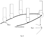
- gouge or collision may exist between the machining tool and the work piece in normal path generated by offline programming.
- the machining tool will gouge the work piece at the points where the radius of the tool contact point (R tool ) is larger than the radium of the work piece (R part ).
- R tool radius of the tool contact point
- R part radium of the work piece
- the object of the present invention is to provide a novel method and system for machining a work piece by a machining tool, and a robot system using the same, to improve machining efficiency and accuracy. With this solution, high machining efficiency could be achieved as well as collisions could be avoided.
- a method for machining a work piece by a machining tool comprising: defining a customized contact point on the machining tool by setting a contact point height of the machining tool; moving the machining tool against the work piece to apply predefined machining feeds.
- the contact point height is configured to be changeable in one machining path.
- controlling the feed rate of the machining tool to be constant when changing the contact point height of the machining tool.
- the machining tool is in a revolving shape.
- generating a default contact diameter (CD default ) of the machining tool generating a default movement speed (MS default ) of the machining tool; generating a default revolution speed of spindle (RS default ) of the machining tool; calculating the actual contact diameter (CD actual ) in accordance with the customized contact point; modifying the actual revolution speed of spindle (RS actual ) and/or the actual movement speed (MS actual ), to remain the feed rate unchanged.
- RS actual revolution speed of spindle
- MS actual movement speed
- a robot system for machining a work piece including: a manipulator; a machining tool; and a controller, being adapted for controlling the manipulator to operate the machining tool according to the method as described above.
- a system for machining a work piece by a machining tool comprising: a height defining module, configured to define a customized contact point on the machining tool by setting a contact point height of the machining tool; a tool moving module, configured to move the machining tool against the work piece to apply predefined machining feeds.
- the system further comprises: a collision checking module, configured to check a feasibility of the contact point height in a virtual environment, to make sure there is no gouge or collision in its machining path; a height adjusting module, configured to adjust the contact point height if failing to pass the checking.
- a collision checking module configured to check a feasibility of the contact point height in a virtual environment, to make sure there is no gouge or collision in its machining path
- a height adjusting module configured to adjust the contact point height if failing to pass the checking.
- the contact point height is configured to be changeable in one machining path.
- the system further comprises: a feed rate controlling module, configured to control the feed rate of the machining tool to be constant when changing the contact point height of the machining tool.
- the machining tool is in a revolving shape.
- the system further comprises: a contact diameter generating module, configured to generate a default contact diameter (CD default ) of the machining tool; a movement speed generating module, configured to generate a default movement speed
- MS default of the machining tool
- a revolution speed generating module configured to generate a default revolution speed of spindle (RS default ) of the machining tool
- a calculating module configured to calculate the actual contact diameter (CD actual ) in accordance with the customized contact point
- a modifying module configured to modify the actual revolution speed of spindle (RS actual ) and/or the actual movement speed (MS actual ), to remain the feed rate unchanged.
- the modifying module is configured to modify the actual revolution speed of spindle (RS actual ) into (CD default /CD actual ) ⁇ RS default , if the actual movement speed (MS actual ) remains the same.
- the modifying module is configured to modify the actual movement speed (MS actual ) into (CD default - CD actual ) ⁇ RS default )/2 + MS default , if the actual revolution speed of spindle (RS actual ) remains the same.
- the present invention can achieve several advantages as below.
- the present invention is easy to improve efficiency of machining by adjusting the contact height.
- the present invention can provide more available options for avoiding gouges and collisions on the path and able to use different contact points for a machining tool.
- the present invention can increase offline programming efficiency, and it can also provide more flexible tool path and more reasonable feed rate.
- the present invention can avoid tool change and reducing cycle time.
- the present invention can improve the machining accuracy.
- embodiments of the present application provide a new method and system for machining a work piece by a machining tool.
- flexible contact point enables users to customize a contact point on a machining tool based on actual requirements so that high machining efficiency could be achieved as well as gouges or collisions could be avoided.
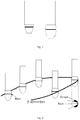
- Fig. 4 is a section view of two different machining tools which the present invention can apply to.
- the machining tool relatively moves against the work piece to apply machining feeds therebetween. Namely the machining tool moves while the work piece keeps still, or the work piece moves while the machining tool keeps still.
- the tool is shaped like a circular truncated cone or an ellipsoid, as can be seen in Fig. 4 . In these situations, the machining tool is in a revolving shape. But it should be noted that the present disclosure is not limit in this regard.
- a primary motion is provided by rotating the machining tool around its axis and the rotating machining tool removes the material from the contact points at the work piece to generate a desired shape, such as deburring and side-machining.
- the feed motion is achieved by relative motion of the machining tool and the work piece.
- another parameter contact point height can also be introduced for defining a customized contact point on the tool, as it can be seen in Fig. 4 .
- the contact point is certainly defined. Then, the offline programming will use the point to contact and work on the work piece and use the normal of the point to calculate the relative posture for the machining target.
- users can define a customized contact point on the machining tool by setting a contact point height of the machining tool, and then move the machining tool against the work piece to apply predefined machining feeds.
- a feasibility of the contact point height can be checked in a virtual environment, to make sure there is no gouge or collision in its machining path. User can adjust the contact point height if failing to pass the checking.
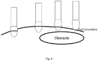
- FIG. 6 Another example is shown in Fig. 6 .
- An obstacle is close to the machining path, so collision will exist in some parts of the path with the default contact point height.
- a lower contact height is set, a smaller contact diameter could be got so that the collisions with obstacles could be eliminated.
- the machining efficiency is proportional to the tool diameter.
- the contact point height can be changeable in one machining path. User can set lower contact height for a special purpose to avoid gouges and collisions in partial machining path, but using a larger contact diameter along the rest of the path to achieve high machining efficiency.
- the present disclosure is advantageous because it is easy to improve machining efficiency of machining by adjusting the contact height according to different environment. Also, it provides more options for avoiding gouges and collisions on the machining path and is able to use different contact points for a tool. So it can increase offline programming efficiency and make tool path more flexible and feed rate more reasonable.
- auto-adaptive feed rate is introduced together with the contact point and enables automatic calculation of proper feed rates based on different contact points.
- this solution by binding the feed rate with contact height, the machining accuracy becomes better than that using the same feed rate regardless of contact height. This could also reduce programming time since users do not need to set the feed rate manually.
- two parameters Movement Speed and Revolution Speed of Spindle are introduced to represent two feed rate states as shown in Table 1.
- Table 1 Default Contact diameter and default feed rate Default Contact diameter Default Feed Rate Movement Speed Revolution speed of spindle CD default MS default RS default
- Table 2 Keep move speed Actual Contact diameter Actual Feed Rate Movement Speed Revolution speed of spindle CD actual MS default (CD default /CD actual )*RS default
- RS actual revolution speed of spindle
- MS actual actual movement speed
- the feed rate of machining target can be automatically calculated by the three strategies as described above.
- the present disclosure is advantageous because users can control the feed rate of the machining tool to be adaptive or constant when changing the contact point height of the machining tool.
- the machining accuracy becomes better compared with the same movement speed and same revolution speed of spindle.
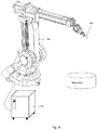
- Fig. 9 illustrates a robot system performing the machining process according to an embodiment of present invention.
- the robot system 5 includes a manipulator 500, a machining tool 501 and a controller 502.
- the manipulator 500 is arranged to hold the machining tool 501.
- the controller 502 can be offline programmed to control the manipulator 500 to operate the machining tool 501 according to the method as described above.
- a system for controlling a machining of a work piece comprises: a height defining module, which can define a customized contact point on the machining tool by setting a contact point height of the machining tool; and a tool moving module, which can move the machining tool against the work piece to apply predefined machining feeds.
- the system further comprises: a collision checking module, which can check a feasibility of the contact point height in a virtual environment, to make sure there is no gouge or collision in its machining path; and a height adjusting module, which can adjust the contact point height if failing to pass the checking.
- a collision checking module which can check a feasibility of the contact point height in a virtual environment, to make sure there is no gouge or collision in its machining path
- a height adjusting module which can adjust the contact point height if failing to pass the checking.
- the contact point height may be changeable in one machining path.
- the system further comprises: a feed rate controlling module, which can control the feed rate of the machining tool to be constant when changing the contact point height of the machining tool.
- the machining tool is in a revolving shape.
- the system further comprises: a contact diameter generating module, which can generate a default contact diameter (CD default ) of the machining tool; a movement speed generating module, which can generate a default movement speed (MS default ) of the machining tool; a revolution speed generating module, which can generate a default revolution speed of spindle (RS default ) of the machining tool; a calculating module, which can calculate the actual contact diameter (CD actual ) in accordance with the customized contact point; a modifying module, which can modify the actual revolution speed of spindle (RS actual ) and/or the actual movement speed (MS actual ), to remain the feed rate unchanged.
- a contact diameter generating module which can generate a default contact diameter (CD default ) of the machining tool
- a movement speed generating module which can generate a default movement speed (MS default ) of the machining tool
- a revolution speed generating module which can generate a default revolution speed of spindle (RS default ) of the machining tool
- a calculating module which can calculate the
- the modifying module can modify the actual revolution speed of spindle (RS actual ) into (CD default /CD actual ) ⁇ RS default , if the actual movement speed (MS actual ) remains the same.
- the modifying module can modify the actual movement speed (MS actual ) into (CD default - CD actual ) ⁇ RS default )/2 + MS default , if the actual revolution speed of spindle (RS actual ) remains the same.
- the components of the system may be a hardware module or a software unit module.
- the system may be implemented partially or completely with software and/or firmware, for example, implemented as a computer program product embodied in a computer readable medium.
- the system may be implemented partially or completely based on hardware, for example, as an integrated circuit (IC), an application-specific integrated circuit (ASIC), a system on chip (SOC), a field programmable gate array (FPGA), and so forth.
- IC integrated circuit
- ASIC application-specific integrated circuit
- SOC system on chip
- FPGA field programmable gate array
Claims (13)
- Procédé d'usinage d'une pièce à usiner par un outil d'usinage (501), comprenant :la définition d'un point de contact personnalisé sur l'outil d'usinage (501) par fixation d'une hauteur de point de contact de l'outil d'usinage (501) ;le déplacement de l'outil d'usinage (501) pour l'amener contre la pièce à usiner dans le but d'appliquer des avances d'usinage prédéfinies ;la génération d'un diamètre de contact par défaut (CDdefault) de l'outil d'usinage (501) ;la génération d'une vitesse de déplacement par défaut (MSdefault) de l'outil d'usinage (501) ;la génération d'une vitesse de rotation par défaut de broche (RSdefault) de l'outil d'usinage (501) ;le calcul du diamètre de contact effectif (CDactual) conformément au point de contact personnalisé ;la modification de la vitesse de rotation effective de broche (RSactual) et/ou de la vitesse de déplacement effective (MSactual) dans le but de maintenir le taux d'avance inchangé.
- Procédé selon la revendication 1, caractérisé par :la vérification d'une faisabilité de la hauteur de point de contact dans un environnement virtuel dans le but d'assurer l'absence d'enfoncement ou de collision dans sa trajectoire d'usinage ;le réglage de la hauteur de point de contact en cas d'échec de la vérification.
- Procédé selon la revendication 1, caractérisé en ce que :
la hauteur de point de contact est configurée pour pouvoir être changée dans une trajectoire d'usinage. - Procédé selon la revendication 1, caractérisé par :
la commande du taux d'avance de l'outil d'usinage pour le maintenir constant lors d'un changement de la hauteur de point de contact de l'outil d'usinage. - Procédé selon la revendication 4, caractérisé en ce que : l'outil d'usinage prend une forme de révolution.
- Procédé selon la revendication 1, caractérisé en ce que :la vitesse de rotation effective de broche (RSactual) est modifiée pour devenir (CDdefault/CDactual) ∗RSdefault si la vitesse de déplacement effective (MSactual) reste la même ;la vitesse de déplacement effective (MSactual) est modifiée pour devenir (CDdefault - CDactual) ∗RSdefault/2 + MSdefault si la vitesse de rotation effective de broche (RSactual) reste la même ; oula vitesse de rotation effective de broche (RSactual) et la vitesse de déplacement effective (MSactual) sont modifiées pour vérifier l'équation suivante :

- Système pour l'usinage d'une pièce à usiner par un outil d'usinage (501), comprenant :un module de définition de hauteur, configuré pour définir un point de contact personnalisé sur l'outil d'usinage (501) en fixant une hauteur de point de contact de l'outil d'usinage (501) ;un module de déplacement d'outil, configuré pour déplacer l'outil d'usinage (501) pour l'amener contre la pièce à usiner dans le but d'appliquer des avances d'usinage prédéfinies ;un module de génération de diamètre de contact, configuré pour générer un diamètre de contact par défaut (CDdefault) de l'outil d'usinage (501) ;un module de génération de vitesse de déplacement, configuré pour générer une vitesse de déplacement par défaut (MSdefault) de l'outil d'usinage (501) ;un module de génération de vitesse de rotation, configuré pour générer une vitesse de rotation par défaut de broche (RSdefault) de l'outil d'usinage (501) ;un module de calcul, configuré pour calculer le diamètre de contact effectif (CDactual) conformément au point de contact personnalisé ;un module de modification, configuré pour modifier la vitesse de rotation effective de broche (RSactual) et/ou la vitesse de déplacement effective (MSactual) dans le but de maintenir le taux d'avance inchangé.
- Système selon la revendication 7, le système étant caractérisé en ce qu'il comprend en outre :un module de vérification de collision configuré pour vérifier une faisabilité de la hauteur de point de contact dans un environnement virtuel dans le but d'assurer l'absence d'enfoncement ou de collision dans sa trajectoire d'usinage ;un module de réglage de hauteur configuré pour régler la hauteur de point de contact en cas d'échec de la vérification.
- Système selon la revendication 8, caractérisé en ce que :
la hauteur de point de contact est configurée pour pouvoir être changée dans une trajectoire d'usinage. - Système selon la revendication 7, le système étant caractérisé en ce qu'il comprend en outre :
un module de commande de taux d'avance, configuré pour commander le taux d'avance de l'outil d'usinage pour le maintenir constant lors d'un changement de la hauteur de point de contact de l'outil d'usinage. - Système selon la revendication 10, caractérisé en ce que :
l'outil d'usinage prend une forme de révolution. - Système selon la revendication 11, caractérisé en ce que :le module de modification est configuré pour modifier la vitesse de rotation effective de broche (RSactual) pour qu'elle devienne (CDdefault/CDactual) ∗RSdefault si la vitesse de déplacement effective (MSactual) reste la même ;le module de modification est configuré pour modifier la vitesse de déplacement effective (MSactual) pour qu'elle devienne (CDdefault - CDactual) ∗RSdefault/2 + MSdefault si la vitesse de rotation effective de broche (RSactual) reste la même ; oule module de modification est configuré pour modifier la vitesse de rotation effective de broche (RSactual) et la vitesse de déplacement effective (MSactual) pour qu'elles vérifient l'équation suivante :

- Système robot, comprenant un système selon l'une quelconque des revendications 7 à 12, pour l'usinage d'une pièce à usiner, comportant : un manipulateur, un outil d'usinage (501) ; et
une unité de commande comprenant les modules de l'une quelconque des revendications 7, 8, 10 et 12, l'unité de commande étant adaptée à commander au manipulateur de faire fonctionner l'outil d'usinage (501) selon le procédé exposé dans l'une quelconque des revendications 1 à 6.
Applications Claiming Priority (1)
| Application Number | Priority Date | Filing Date | Title |
|---|---|---|---|
| PCT/CN2015/094177 WO2017079892A1 (fr) | 2015-11-10 | 2015-11-10 | Procédé et système pour usinage, et système robotique |
Publications (3)
| Publication Number | Publication Date |
|---|---|
| EP3374128A1 EP3374128A1 (fr) | 2018-09-19 |
| EP3374128A4 EP3374128A4 (fr) | 2019-07-17 |
| EP3374128B1 true EP3374128B1 (fr) | 2020-12-30 |
Family
ID=58694577
Family Applications (1)
| Application Number | Title | Priority Date | Filing Date |
|---|---|---|---|
| EP15908022.5A Active EP3374128B1 (fr) | 2015-11-10 | 2015-11-10 | Procédé et système pour usinage, et système robotique |
Country Status (4)
| Country | Link |
|---|---|
| US (1) | US10946498B2 (fr) |
| EP (1) | EP3374128B1 (fr) |
| CN (1) | CN107249817B (fr) |
| WO (1) | WO2017079892A1 (fr) |
Families Citing this family (3)
| Publication number | Priority date | Publication date | Assignee | Title |
|---|---|---|---|---|
| WO2017079892A1 (fr) * | 2015-11-10 | 2017-05-18 | Abb Schweiz Ag | Procédé et système pour usinage, et système robotique |
| GB2557952B (en) * | 2016-12-16 | 2022-06-15 | Zeeko Innovations Ltd | Methods and apparatus for shaping workpieces |
| JP7120512B2 (ja) * | 2019-11-22 | 2022-08-17 | Smc株式会社 | 軌跡制御装置 |
Family Cites Families (30)
| Publication number | Priority date | Publication date | Assignee | Title |
|---|---|---|---|---|
| US4054010A (en) * | 1976-01-20 | 1977-10-18 | Headway Research, Inc. | Apparatus for grinding edges of planar workpieces |
| US4777769A (en) * | 1987-04-13 | 1988-10-18 | General Electric Company | System and method of automated grinding |
| JPS63288658A (ja) * | 1987-05-21 | 1988-11-25 | Mitsubishi Electric Corp | バリ取り用ロボット装置 |
| JP2719345B2 (ja) | 1988-03-30 | 1998-02-25 | 豊田工機株式会社 | 力センサを用いた加工制御装置 |
| US5126645A (en) * | 1989-09-30 | 1992-06-30 | Kabushiki Kaisha Toshiba | Grinder robot |
| GB8922451D0 (en) | 1989-10-05 | 1989-11-22 | Rolls Royce Plc | Compliant mount and mechanical stop |
| DE4110209C2 (de) * | 1991-03-28 | 1993-11-18 | Roland Man Druckmasch | Vorrichtung zur Justierung einer CNC-gesteuerten Schleifmaschine |
| US5668453A (en) * | 1993-11-05 | 1997-09-16 | Nippon Telegraph And Telephone Corporation | Method of calculating points and normal lines of contact and apparatus therefor |
| JPH07132435A (ja) | 1993-11-08 | 1995-05-23 | Nippon Telegr & Teleph Corp <Ntt> | ロボット作業算出教示方法 |
| JP3506814B2 (ja) * | 1995-07-11 | 2004-03-15 | 東芝機械株式会社 | 数値制御装置 |
| JP4162332B2 (ja) * | 1999-07-07 | 2008-10-08 | 株式会社ニデック | 眼鏡レンズ加工装置 |
| US6439961B1 (en) * | 2000-01-21 | 2002-08-27 | Hammond Machinery Builders, Inc. | Machining cell and method for deburring the root of a turbine blade |
| DE10020879B4 (de) | 2000-04-28 | 2006-01-19 | Dipl.-Ing. Laempe Gmbh | Vorrichtung zum mechanischen Vor- und/oder Fertigbearbeiten von Gussteilen |
| CN101774048B (zh) * | 2010-03-15 | 2012-07-18 | 陕西秦川机械发展股份有限公司 | 一种锥齿轮加工方法 |
| US8784155B2 (en) * | 2011-05-16 | 2014-07-22 | Huaizhong Guo | Multi-carriage symmetrical numerically controlled coordinate grinding machine |
| JP5708324B2 (ja) * | 2011-07-11 | 2015-04-30 | 日本精工株式会社 | 研削加工盤及び研削加工方法 |
| DE102011086051A1 (de) | 2011-11-10 | 2013-07-04 | Bayerische Motoren Werke Aktiengesellschaft | Aufsatz für ein spanabhebendes Werkzeug |
| JP2013184276A (ja) | 2012-03-09 | 2013-09-19 | Disco Corp | バイト切削方法 |
| JP2013184277A (ja) | 2012-03-09 | 2013-09-19 | Disco Corp | バイト切削装置 |
| PL2700472T3 (pl) * | 2012-05-15 | 2020-11-30 | Nittan Valve Co., Ltd. | Sposób obróbki obu powierzchni końcowych pręta okrągłego |
| JP5426722B2 (ja) * | 2012-05-24 | 2014-02-26 | ファナック株式会社 | ロボットプログラム変更装置 |
| US20140113525A1 (en) * | 2012-10-22 | 2014-04-24 | Apple Inc. | Methods for finishing surfaces using tool center point shift techniques |
| JP6127530B2 (ja) * | 2013-01-17 | 2017-05-17 | 株式会社ニデック | 眼鏡レンズ加工装置および加工制御データ作成プログラム |
| JP5845212B2 (ja) * | 2013-06-28 | 2016-01-20 | ファナック株式会社 | 視覚センサ及び力センサを備えたバリ取り装置 |
| CN104972362B (zh) | 2014-04-14 | 2017-10-31 | 沈阳远大科技园有限公司 | 智能力控机器人磨削加工系统和方法 |
| EP3356070A4 (fr) * | 2015-09-29 | 2019-07-17 | ABB Schweiz AG | Procédé et système pour usinage |
| WO2017079892A1 (fr) * | 2015-11-10 | 2017-05-18 | Abb Schweiz Ag | Procédé et système pour usinage, et système robotique |
| JP6457435B2 (ja) * | 2016-05-26 | 2019-01-23 | ファナック株式会社 | 研削ロボットシステム |
| GB201614685D0 (en) * | 2016-08-31 | 2016-10-12 | Rolls Royce Plc | Method and apparatus for monitoring abrasive machining |
| JP6457468B2 (ja) * | 2016-12-08 | 2019-01-23 | ファナック株式会社 | バリ取り装置 |
-
2015
- 2015-11-10 WO PCT/CN2015/094177 patent/WO2017079892A1/fr active Application Filing
- 2015-11-10 CN CN201580075761.6A patent/CN107249817B/zh active Active
- 2015-11-10 EP EP15908022.5A patent/EP3374128B1/fr active Active
- 2015-11-10 US US15/567,404 patent/US10946498B2/en active Active
Non-Patent Citations (1)
| Title |
|---|
| None * |
Also Published As
| Publication number | Publication date |
|---|---|
| EP3374128A4 (fr) | 2019-07-17 |
| US10946498B2 (en) | 2021-03-16 |
| EP3374128A1 (fr) | 2018-09-19 |
| CN107249817B (zh) | 2020-04-24 |
| CN107249817A (zh) | 2017-10-13 |
| WO2017079892A1 (fr) | 2017-05-18 |
| US20180141184A1 (en) | 2018-05-24 |
Similar Documents
| Publication | Publication Date | Title |
|---|---|---|
| EP3374128B1 (fr) | Procédé et système pour usinage, et système robotique | |
| US8403605B2 (en) | Plunge milling method | |
| JP2017530016A (ja) | 歯部を加工する方法及び加工用工具並びに工作機械 | |
| EP2407273B1 (fr) | Procédé de commande de rotation de broche principale et dispositif de commande de machine-outil | |
| JP5619640B2 (ja) | 工作機械、加工方法、プログラム及びncデータ生成装置 | |
| JP6209392B2 (ja) | 干渉確認装置 | |
| US10088824B2 (en) | Toolpath evaluation method, toolpath generation method, and toolpath generation device | |
| WO2013179366A1 (fr) | Dispositif de commande numérique | |
| US20180104749A1 (en) | Method for Machining Flat Surfaces of a Workpiece | |
| CN105229543A (zh) | 数控装置 | |
| WO2015141545A1 (fr) | Procédé et dispositif d'optimisation des conditions de coupe d'une machine-outil | |
| US20170097629A1 (en) | Numerical controller having function of automatically selecting parameter based on size of machining area | |
| CN104275516B (zh) | 叶轮以及该叶轮的加工方法 | |
| JP2020066119A (ja) | 工作機械及び制御装置 | |
| US9849547B2 (en) | Manufacturing apparatus and manufacturing method for manufacturing less unbalanced blower blade | |
| JP5413913B2 (ja) | 旋削による非円形加工方法 | |
| US20150261214A1 (en) | Numerical control unit and nc program creating unit | |
| US10088832B2 (en) | Method of generating tool path by modifying existing tool path and device practicing the same | |
| EP2907621B1 (fr) | Procédé de génération de trajet d'outil, dispositif de commande de machine-outil et dispositif de génération de trajet d'outil | |
| JP6565399B2 (ja) | 歯車加工装置 | |
| JP5929065B2 (ja) | Ncデータ補正装置 | |
| US20170090453A1 (en) | Numerical controller for controlling collision position of cutter tip of tool and workpiece | |
| EP3476363A1 (fr) | Procédé de traitement pour la fabrication de dispositifs dentaires | |
| WO2017191802A1 (fr) | Procédé de correction de trajectoire de bord de coupe, support d'enregistrement, et programme | |
| KR20200131734A (ko) | 공작 기계 및 공작 기계의 제어 방법 |
Legal Events
| Date | Code | Title | Description |
|---|---|---|---|
| STAA | Information on the status of an ep patent application or granted ep patent |
Free format text: STATUS: THE INTERNATIONAL PUBLICATION HAS BEEN MADE |
|
| PUAI | Public reference made under article 153(3) epc to a published international application that has entered the european phase |
Free format text: ORIGINAL CODE: 0009012 |
|
| STAA | Information on the status of an ep patent application or granted ep patent |
Free format text: STATUS: REQUEST FOR EXAMINATION WAS MADE |
|
| 17P | Request for examination filed |
Effective date: 20171005 |
|
| AK | Designated contracting states |
Kind code of ref document: A1 Designated state(s): AL AT BE BG CH CY CZ DE DK EE ES FI FR GB GR HR HU IE IS IT LI LT LU LV MC MK MT NL NO PL PT RO RS SE SI SK SM TR |
|
| AX | Request for extension of the european patent |
Extension state: BA ME |
|
| DAV | Request for validation of the european patent (deleted) | ||
| DAX | Request for extension of the european patent (deleted) | ||
| A4 | Supplementary search report drawn up and despatched |
Effective date: 20190619 |
|
| RIC1 | Information provided on ipc code assigned before grant |
Ipc: B25J 9/16 20060101AFI20190613BHEP Ipc: G05B 19/4093 20060101ALN20190613BHEP Ipc: G05B 19/416 20060101ALN20190613BHEP |
|
| RIC1 | Information provided on ipc code assigned before grant |
Ipc: G05B 19/416 20060101ALN20191121BHEP Ipc: B24B 9/00 20060101ALI20191121BHEP Ipc: B24B 27/00 20060101ALI20191121BHEP Ipc: B24B 51/00 20060101ALI20191121BHEP Ipc: B25J 9/16 20060101AFI20191121BHEP Ipc: G05B 19/4093 20060101ALN20191121BHEP |
|
| GRAP | Despatch of communication of intention to grant a patent |
Free format text: ORIGINAL CODE: EPIDOSNIGR1 |
|
| STAA | Information on the status of an ep patent application or granted ep patent |
Free format text: STATUS: GRANT OF PATENT IS INTENDED |
|
| INTG | Intention to grant announced |
Effective date: 20200103 |
|
| GRAJ | Information related to disapproval of communication of intention to grant by the applicant or resumption of examination proceedings by the epo deleted |
Free format text: ORIGINAL CODE: EPIDOSDIGR1 |
|
| STAA | Information on the status of an ep patent application or granted ep patent |
Free format text: STATUS: REQUEST FOR EXAMINATION WAS MADE |
|
| INTC | Intention to grant announced (deleted) | ||
| RIC1 | Information provided on ipc code assigned before grant |
Ipc: G05B 19/416 20060101ALN20200428BHEP Ipc: B24B 51/00 20060101ALI20200428BHEP Ipc: B25J 9/16 20060101AFI20200428BHEP Ipc: G05B 19/4093 20060101ALN20200428BHEP Ipc: B24B 27/00 20060101ALI20200428BHEP Ipc: B24B 9/00 20060101ALI20200428BHEP |
|
| REG | Reference to a national code |
Ref country code: DE Ref legal event code: R079 Ref document number: 602015064313 Country of ref document: DE Free format text: PREVIOUS MAIN CLASS: B24B0009000000 Ipc: B25J0009160000 |
|
| GRAP | Despatch of communication of intention to grant a patent |
Free format text: ORIGINAL CODE: EPIDOSNIGR1 |
|
| STAA | Information on the status of an ep patent application or granted ep patent |
Free format text: STATUS: GRANT OF PATENT IS INTENDED |
|
| RIC1 | Information provided on ipc code assigned before grant |
Ipc: B24B 27/00 20060101ALI20200715BHEP Ipc: B24B 51/00 20060101ALI20200715BHEP Ipc: G05B 19/416 20060101ALN20200715BHEP Ipc: B24B 9/00 20060101ALI20200715BHEP Ipc: B25J 9/16 20060101AFI20200715BHEP Ipc: G05B 19/4093 20060101ALN20200715BHEP |
|
| INTG | Intention to grant announced |
Effective date: 20200729 |
|
| GRAS | Grant fee paid |
Free format text: ORIGINAL CODE: EPIDOSNIGR3 |
|
| GRAA | (expected) grant |
Free format text: ORIGINAL CODE: 0009210 |
|
| STAA | Information on the status of an ep patent application or granted ep patent |
Free format text: STATUS: THE PATENT HAS BEEN GRANTED |
|
| RAP1 | Party data changed (applicant data changed or rights of an application transferred) |
Owner name: ABB SCHWEIZ AG |
|
| AK | Designated contracting states |
Kind code of ref document: B1 Designated state(s): AL AT BE BG CH CY CZ DE DK EE ES FI FR GB GR HR HU IE IS IT LI LT LU LV MC MK MT NL NO PL PT RO RS SE SI SK SM TR |
|
| REG | Reference to a national code |
Ref country code: GB Ref legal event code: FG4D |
|
| REG | Reference to a national code |
Ref country code: AT Ref legal event code: REF Ref document number: 1349463 Country of ref document: AT Kind code of ref document: T Effective date: 20210115 |
|
| REG | Reference to a national code |
Ref country code: DE Ref legal event code: R096 Ref document number: 602015064313 Country of ref document: DE |
|
| REG | Reference to a national code |
Ref country code: IE Ref legal event code: FG4D |
|
| PG25 | Lapsed in a contracting state [announced via postgrant information from national office to epo] |
Ref country code: RS Free format text: LAPSE BECAUSE OF FAILURE TO SUBMIT A TRANSLATION OF THE DESCRIPTION OR TO PAY THE FEE WITHIN THE PRESCRIBED TIME-LIMIT Effective date: 20201230 Ref country code: FI Free format text: LAPSE BECAUSE OF FAILURE TO SUBMIT A TRANSLATION OF THE DESCRIPTION OR TO PAY THE FEE WITHIN THE PRESCRIBED TIME-LIMIT Effective date: 20201230 Ref country code: NO Free format text: LAPSE BECAUSE OF FAILURE TO SUBMIT A TRANSLATION OF THE DESCRIPTION OR TO PAY THE FEE WITHIN THE PRESCRIBED TIME-LIMIT Effective date: 20210330 Ref country code: GR Free format text: LAPSE BECAUSE OF FAILURE TO SUBMIT A TRANSLATION OF THE DESCRIPTION OR TO PAY THE FEE WITHIN THE PRESCRIBED TIME-LIMIT Effective date: 20210331 |
|
| REG | Reference to a national code |
Ref country code: AT Ref legal event code: MK05 Ref document number: 1349463 Country of ref document: AT Kind code of ref document: T Effective date: 20201230 |
|
| PG25 | Lapsed in a contracting state [announced via postgrant information from national office to epo] |
Ref country code: BG Free format text: LAPSE BECAUSE OF FAILURE TO SUBMIT A TRANSLATION OF THE DESCRIPTION OR TO PAY THE FEE WITHIN THE PRESCRIBED TIME-LIMIT Effective date: 20210330 Ref country code: SE Free format text: LAPSE BECAUSE OF FAILURE TO SUBMIT A TRANSLATION OF THE DESCRIPTION OR TO PAY THE FEE WITHIN THE PRESCRIBED TIME-LIMIT Effective date: 20201230 Ref country code: LV Free format text: LAPSE BECAUSE OF FAILURE TO SUBMIT A TRANSLATION OF THE DESCRIPTION OR TO PAY THE FEE WITHIN THE PRESCRIBED TIME-LIMIT Effective date: 20201230 |
|
| REG | Reference to a national code |
Ref country code: NL Ref legal event code: MP Effective date: 20201230 |
|
| PG25 | Lapsed in a contracting state [announced via postgrant information from national office to epo] |
Ref country code: HR Free format text: LAPSE BECAUSE OF FAILURE TO SUBMIT A TRANSLATION OF THE DESCRIPTION OR TO PAY THE FEE WITHIN THE PRESCRIBED TIME-LIMIT Effective date: 20201230 |
|
| REG | Reference to a national code |
Ref country code: LT Ref legal event code: MG9D |
|
| PG25 | Lapsed in a contracting state [announced via postgrant information from national office to epo] |
Ref country code: SK Free format text: LAPSE BECAUSE OF FAILURE TO SUBMIT A TRANSLATION OF THE DESCRIPTION OR TO PAY THE FEE WITHIN THE PRESCRIBED TIME-LIMIT Effective date: 20201230 Ref country code: PT Free format text: LAPSE BECAUSE OF FAILURE TO SUBMIT A TRANSLATION OF THE DESCRIPTION OR TO PAY THE FEE WITHIN THE PRESCRIBED TIME-LIMIT Effective date: 20210430 Ref country code: RO Free format text: LAPSE BECAUSE OF FAILURE TO SUBMIT A TRANSLATION OF THE DESCRIPTION OR TO PAY THE FEE WITHIN THE PRESCRIBED TIME-LIMIT Effective date: 20201230 Ref country code: EE Free format text: LAPSE BECAUSE OF FAILURE TO SUBMIT A TRANSLATION OF THE DESCRIPTION OR TO PAY THE FEE WITHIN THE PRESCRIBED TIME-LIMIT Effective date: 20201230 Ref country code: CZ Free format text: LAPSE BECAUSE OF FAILURE TO SUBMIT A TRANSLATION OF THE DESCRIPTION OR TO PAY THE FEE WITHIN THE PRESCRIBED TIME-LIMIT Effective date: 20201230 Ref country code: LT Free format text: LAPSE BECAUSE OF FAILURE TO SUBMIT A TRANSLATION OF THE DESCRIPTION OR TO PAY THE FEE WITHIN THE PRESCRIBED TIME-LIMIT Effective date: 20201230 |
|
| PG25 | Lapsed in a contracting state [announced via postgrant information from national office to epo] |
Ref country code: PL Free format text: LAPSE BECAUSE OF FAILURE TO SUBMIT A TRANSLATION OF THE DESCRIPTION OR TO PAY THE FEE WITHIN THE PRESCRIBED TIME-LIMIT Effective date: 20201230 Ref country code: AT Free format text: LAPSE BECAUSE OF FAILURE TO SUBMIT A TRANSLATION OF THE DESCRIPTION OR TO PAY THE FEE WITHIN THE PRESCRIBED TIME-LIMIT Effective date: 20201230 |
|
| PG25 | Lapsed in a contracting state [announced via postgrant information from national office to epo] |
Ref country code: IS Free format text: LAPSE BECAUSE OF FAILURE TO SUBMIT A TRANSLATION OF THE DESCRIPTION OR TO PAY THE FEE WITHIN THE PRESCRIBED TIME-LIMIT Effective date: 20210430 |
|
| REG | Reference to a national code |
Ref country code: DE Ref legal event code: R097 Ref document number: 602015064313 Country of ref document: DE |
|
| PG25 | Lapsed in a contracting state [announced via postgrant information from national office to epo] |
Ref country code: AL Free format text: LAPSE BECAUSE OF FAILURE TO SUBMIT A TRANSLATION OF THE DESCRIPTION OR TO PAY THE FEE WITHIN THE PRESCRIBED TIME-LIMIT Effective date: 20201230 |
|
| PLBE | No opposition filed within time limit |
Free format text: ORIGINAL CODE: 0009261 |
|
| STAA | Information on the status of an ep patent application or granted ep patent |
Free format text: STATUS: NO OPPOSITION FILED WITHIN TIME LIMIT |
|
| PG25 | Lapsed in a contracting state [announced via postgrant information from national office to epo] |
Ref country code: DK Free format text: LAPSE BECAUSE OF FAILURE TO SUBMIT A TRANSLATION OF THE DESCRIPTION OR TO PAY THE FEE WITHIN THE PRESCRIBED TIME-LIMIT Effective date: 20201230 |
|
| 26N | No opposition filed |
Effective date: 20211001 |
|
| PG25 | Lapsed in a contracting state [announced via postgrant information from national office to epo] |
Ref country code: ES Free format text: LAPSE BECAUSE OF FAILURE TO SUBMIT A TRANSLATION OF THE DESCRIPTION OR TO PAY THE FEE WITHIN THE PRESCRIBED TIME-LIMIT Effective date: 20201230 |
|
| PG25 | Lapsed in a contracting state [announced via postgrant information from national office to epo] |
Ref country code: SI Free format text: LAPSE BECAUSE OF FAILURE TO SUBMIT A TRANSLATION OF THE DESCRIPTION OR TO PAY THE FEE WITHIN THE PRESCRIBED TIME-LIMIT Effective date: 20201230 |
|
| PG25 | Lapsed in a contracting state [announced via postgrant information from national office to epo] |
Ref country code: IS Free format text: LAPSE BECAUSE OF FAILURE TO SUBMIT A TRANSLATION OF THE DESCRIPTION OR TO PAY THE FEE WITHIN THE PRESCRIBED TIME-LIMIT Effective date: 20210430 |
|
| PG25 | Lapsed in a contracting state [announced via postgrant information from national office to epo] |
Ref country code: MC Free format text: LAPSE BECAUSE OF FAILURE TO SUBMIT A TRANSLATION OF THE DESCRIPTION OR TO PAY THE FEE WITHIN THE PRESCRIBED TIME-LIMIT Effective date: 20201230 |
|
| REG | Reference to a national code |
Ref country code: CH Ref legal event code: PL |
|
| GBPC | Gb: european patent ceased through non-payment of renewal fee |
Effective date: 20211110 |
|
| PG25 | Lapsed in a contracting state [announced via postgrant information from national office to epo] |
Ref country code: LU Free format text: LAPSE BECAUSE OF NON-PAYMENT OF DUE FEES Effective date: 20211110 Ref country code: BE Free format text: LAPSE BECAUSE OF NON-PAYMENT OF DUE FEES Effective date: 20211130 |
|
| REG | Reference to a national code |
Ref country code: BE Ref legal event code: MM Effective date: 20211130 |
|
| PG25 | Lapsed in a contracting state [announced via postgrant information from national office to epo] |
Ref country code: LI Free format text: LAPSE BECAUSE OF NON-PAYMENT OF DUE FEES Effective date: 20211130 Ref country code: CH Free format text: LAPSE BECAUSE OF NON-PAYMENT OF DUE FEES Effective date: 20211130 |
|
| PG25 | Lapsed in a contracting state [announced via postgrant information from national office to epo] |
Ref country code: IE Free format text: LAPSE BECAUSE OF NON-PAYMENT OF DUE FEES Effective date: 20211110 Ref country code: GB Free format text: LAPSE BECAUSE OF NON-PAYMENT OF DUE FEES Effective date: 20211110 |
|
| PG25 | Lapsed in a contracting state [announced via postgrant information from national office to epo] |
Ref country code: HU Free format text: LAPSE BECAUSE OF FAILURE TO SUBMIT A TRANSLATION OF THE DESCRIPTION OR TO PAY THE FEE WITHIN THE PRESCRIBED TIME-LIMIT; INVALID AB INITIO Effective date: 20151110 |
|
| PG25 | Lapsed in a contracting state [announced via postgrant information from national office to epo] |
Ref country code: NL Free format text: LAPSE BECAUSE OF NON-PAYMENT OF DUE FEES Effective date: 20201230 Ref country code: CY Free format text: LAPSE BECAUSE OF FAILURE TO SUBMIT A TRANSLATION OF THE DESCRIPTION OR TO PAY THE FEE WITHIN THE PRESCRIBED TIME-LIMIT Effective date: 20201230 |
|
| PG25 | Lapsed in a contracting state [announced via postgrant information from national office to epo] |
Ref country code: SM Free format text: LAPSE BECAUSE OF FAILURE TO SUBMIT A TRANSLATION OF THE DESCRIPTION OR TO PAY THE FEE WITHIN THE PRESCRIBED TIME-LIMIT Effective date: 20201230 |
|
| PGFP | Annual fee paid to national office [announced via postgrant information from national office to epo] |
Ref country code: IT Payment date: 20231124 Year of fee payment: 9 Ref country code: FR Payment date: 20231120 Year of fee payment: 9 Ref country code: DE Payment date: 20231121 Year of fee payment: 9 |
|
| PG25 | Lapsed in a contracting state [announced via postgrant information from national office to epo] |
Ref country code: MK Free format text: LAPSE BECAUSE OF FAILURE TO SUBMIT A TRANSLATION OF THE DESCRIPTION OR TO PAY THE FEE WITHIN THE PRESCRIBED TIME-LIMIT Effective date: 20201230 |