EP3373601B1 - Verfahren zur frequenzverzerrung eines audiosignals sowie ein hörgerät zum ausführen dieses verfahrens - Google Patents
Verfahren zur frequenzverzerrung eines audiosignals sowie ein hörgerät zum ausführen dieses verfahrens Download PDFInfo
- Publication number
- EP3373601B1 EP3373601B1 EP18154220.0A EP18154220A EP3373601B1 EP 3373601 B1 EP3373601 B1 EP 3373601B1 EP 18154220 A EP18154220 A EP 18154220A EP 3373601 B1 EP3373601 B1 EP 3373601B1
- Authority
- EP
- European Patent Office
- Prior art keywords
- frequency
- signal
- frequency band
- band
- distortion
- Prior art date
- Legal status (The legal status is an assumption and is not a legal conclusion. Google has not performed a legal analysis and makes no representation as to the accuracy of the status listed.)
- Active
Links
Images



Classifications
-
- H—ELECTRICITY
- H04—ELECTRIC COMMUNICATION TECHNIQUE
- H04R—LOUDSPEAKERS, MICROPHONES, GRAMOPHONE PICK-UPS OR LIKE ACOUSTIC ELECTROMECHANICAL TRANSDUCERS; ELECTRIC HEARING AIDS; PUBLIC ADDRESS SYSTEMS
- H04R3/00—Circuits for transducers
- H04R3/12—Circuits for transducers for distributing signals to two or more loudspeakers
-
- H—ELECTRICITY
- H04—ELECTRIC COMMUNICATION TECHNIQUE
- H04R—LOUDSPEAKERS, MICROPHONES, GRAMOPHONE PICK-UPS OR LIKE ACOUSTIC ELECTROMECHANICAL TRANSDUCERS; ELECTRIC HEARING AIDS; PUBLIC ADDRESS SYSTEMS
- H04R25/00—Electric hearing aids
- H04R25/50—Customised settings for obtaining desired overall acoustical characteristics
- H04R25/505—Customised settings for obtaining desired overall acoustical characteristics using digital signal processing
-
- G—PHYSICS
- G10—MUSICAL INSTRUMENTS; ACOUSTICS
- G10L—SPEECH ANALYSIS TECHNIQUES OR SPEECH SYNTHESIS; SPEECH RECOGNITION; SPEECH OR VOICE PROCESSING TECHNIQUES; SPEECH OR AUDIO CODING OR DECODING
- G10L21/00—Speech or voice signal processing techniques to produce another audible or non-audible signal, e.g. visual or tactile, in order to modify its quality or its intelligibility
- G10L21/02—Speech enhancement, e.g. noise reduction or echo cancellation
- G10L21/0272—Voice signal separating
-
- H—ELECTRICITY
- H04—ELECTRIC COMMUNICATION TECHNIQUE
- H04R—LOUDSPEAKERS, MICROPHONES, GRAMOPHONE PICK-UPS OR LIKE ACOUSTIC ELECTROMECHANICAL TRANSDUCERS; ELECTRIC HEARING AIDS; PUBLIC ADDRESS SYSTEMS
- H04R25/00—Electric hearing aids
- H04R25/35—Electric hearing aids using translation techniques
- H04R25/353—Frequency, e.g. frequency shift or compression
-
- H—ELECTRICITY
- H04—ELECTRIC COMMUNICATION TECHNIQUE
- H04R—LOUDSPEAKERS, MICROPHONES, GRAMOPHONE PICK-UPS OR LIKE ACOUSTIC ELECTROMECHANICAL TRANSDUCERS; ELECTRIC HEARING AIDS; PUBLIC ADDRESS SYSTEMS
- H04R25/00—Electric hearing aids
- H04R25/45—Prevention of acoustic reaction, i.e. acoustic oscillatory feedback
- H04R25/453—Prevention of acoustic reaction, i.e. acoustic oscillatory feedback electronically
-
- H—ELECTRICITY
- H04—ELECTRIC COMMUNICATION TECHNIQUE
- H04R—LOUDSPEAKERS, MICROPHONES, GRAMOPHONE PICK-UPS OR LIKE ACOUSTIC ELECTROMECHANICAL TRANSDUCERS; ELECTRIC HEARING AIDS; PUBLIC ADDRESS SYSTEMS
- H04R2430/00—Signal processing covered by H04R, not provided for in its groups
- H04R2430/03—Synergistic effects of band splitting and sub-band processing
-
- H—ELECTRICITY
- H04—ELECTRIC COMMUNICATION TECHNIQUE
- H04R—LOUDSPEAKERS, MICROPHONES, GRAMOPHONE PICK-UPS OR LIKE ACOUSTIC ELECTROMECHANICAL TRANSDUCERS; ELECTRIC HEARING AIDS; PUBLIC ADDRESS SYSTEMS
- H04R27/00—Public address systems
Definitions
- the invention relates to a method for frequency distortion of an audio signal, wherein different frequency distortions are applied to different signal components of the audio signal, and a frequency-distorted signal is thereby generated.
- Controlling acoustic feedback often plays a central role in the operation of acoustic systems, by means of which sound signals from the environment are reproduced in an electrically amplified manner in the broadest sense, ie also for the operation of hearing aids, for example.
- the acoustic feedback can occur when an output sound signal generated by the acoustic system is partially coupled into an input transducer of the acoustic system, which is provided for picking up the sound signal from the environment and for correspondingly generating an electrical input signal.
- signal components of the output sound signal can be electrically amplified again by the acoustic system, so that interference noises are formed in the output sound signal, which can completely superimpose possible useful signals in the sound signal of the environment until they are completely inaudible.
- Suppression or compensation for acoustic feedback is therefore often provided in the electrical signal path of the acoustic system.
- Such a compensation often takes place by means of an adaptive filter, to which the fully amplified output signal, from which the output sound signal is generated, is supplied as an input variable. A compensation signal is generated from this, which is supplied to the input signal, which has not yet been amplified, to compensate for the feedback.
- Adaptive filter control usually takes place via an error signal, which is formed from the difference between the input signal and the compensation signal.
- the fully amplified output signal in the acoustic system is often subjected to frequency distortion, as a result of which the output signal is decorrelated from the input signal, so that the signal cancellation described can largely be avoided.
- the frequency distortion is usually only applied to a specific frequency range of the amplified signal, for which the latter is filtered at a given division frequency into a signal component to be distorted and a signal component not to be distorted.
- the division frequency In order to suppress the occurrence of artefacts in the output signal as far as possible, the division frequency is mostly adapted to a determined acoustic feedback.
- the implementation of the division frequency usually takes place via high-pass and low-pass filters, which lead to additional latency in the acoustic system.
- the EP 2 244 491 B2 whose priority application as DE 10 2009 018 812 A1 is published, calls a method for operating a hearing aid, which provides for the division of an input signal into a high-frequency and a low-frequency signal component, wherein a frequency distortion is applied to the high-frequency signal component.
- a limit frequency for the division into the high-frequency and low-frequency signal components is determined by analyzing the input signal in such a way that artifacts in an output signal, which is formed using the low-frequency and the frequency-distorted high-frequency signal component, are reduced as far as possible.
- the US 2016 / 0 057 548 A1 describes a method for a hearing aid in which, to suppress acoustic feedback, the frequency spectrum transmitted by the hearing aid is divided into a high-frequency and a low-frequency component at a dividing frequency, with the transfer function of the feedback loop being determined in the high-frequency component of the frequency spectrum, using this Transfer function in the range above the division frequency, the behavior of a transfer function for the low-frequency component is estimated in an environment below the division frequency, and the division frequency is adjusted, if necessary, based on the result of this estimation.
- the invention is therefore based on the object of specifying a method for frequency distortion of an audio signal, which is intended to minimize the latency as far as possible and, in so doing, to suppress the formation of artefacts as far as possible.
- the stated object is achieved according to the invention by the method defined in claim 1 for frequency distortion of an audio signal in a signal processing process in a hearing aid, the audio signal being divided into a plurality of predetermined frequency bands by means of a filter bank, with a band limit frequency being defined by two immediately adjacent frequency bands in each case is determined, based on the audio signal first a target frequency for a boundary between two frequency ranges with different distortion of the frequencies is determined, wherein the target frequency is determined as a critical frequency, which is given by an acoustic feedback to be suppressed on the hearing aid, and based on the target frequency a first frequency band and a second frequency band lying directly above the first frequency band are determined, with that frequency band being determined as the first frequency band, the upper band limit frequency of which is formed by the band limit frequency located directly below the target frequency, and with signal components in the first frequency band having a different distortion of the Frequencies is applied to signal components in the second frequency band.
- the frequency-distorted signal is given in the frequency domain.
- An audio signal generally includes an electrical signal whose signal profile can serve as a carrier of acoustic information and which can be converted into a corresponding sound signal by a suitable output converter.
- the audio signal is divided into a plurality of predefined frequency bands by means of a filter bank.
- the individual frequency bands in particular the band characteristics of the individual frequency bands, such as the respective center frequency and/or bandwidth, are specified here, for example, by a higher-level application, in which the audio signal is used.
- the higher-level application is given, for example, by a signal processing process in a hearing device.
- the individual frequency bands are specified in particular on the basis of the requirements for the signal processing by frequency band in the hearing device.
- Two frequency bands are to be regarded as immediately adjacent in particular if there is no further characteristic frequency of another frequency band between the two characteristic frequencies, which in each case define the position of a frequency band in the frequency space.
- a center frequency of a frequency band or a maximum frequency of the magnitude frequency response is used as such a characteristic frequency.
- the band limit frequency of two immediately adjacent frequency bands should preferably be set so that information about the filter behavior of each of the two frequency bands concerned is provided in the frequency range in which the two frequency bands concerned are adjacent, i.e. in particular in a possible overlapping area.
- the band limit frequency is determined as that frequency for which the two immediately adjacent frequency bands have the same magnitude frequency response, or as the arithmetic or geometric mean between the characteristic frequencies determining the two immediately adjacent frequency bands,
- a (first) target frequency which is a desired limit between two frequency ranges, is initially determined on the basis of the audio signal with different distortion.
- the first and second frequency bands are then indirectly determined on the basis of this target frequency. Since the target frequency is derived from the properties of the audio signal, this target frequency only coincides exactly with one of the band limit frequencies in exceptional cases. As a rule, it is more or less distant from the nearest band cut-off frequency.
- the first target frequency is determined in particular within the framework of the higher-level application of the audio signal, e.g. in the case of a signal processing process in a hearing aid depending on the need for frequency-distorted signals in a specific frequency range occurring in the hearing aid.
- the first target frequency is preferably determined in such a way that it meets the requirements for the desired frequency distortion of the audio signal by the higher-level application particularly well, so that in particular the first target frequency for the higher-level application of the audio signal represents a critical value in terms of frequency distortion, at which suitably a change in the frequency distortion of the audio signal has to take place preferentially.
- such a critical frequency for the frequency distortion is given, for example, by acoustic feedback on the hearing aid that is to be suppressed, which is preferably to be carried out in the smallest possible frequency range, with frequency distortion being used as part of the suppression of the acoustic feedback becomes.
- the critical frequency selected is, for example, the minimum frequency for which acoustic feedback must be suppressed in order to ensure an overall gain of less than one in the closed loop formed from the acoustic feedback path and the signal processing.
- the first frequency band and the second frequency band lying directly above the first frequency band are preferably determined solely on the basis of the first target frequency, for example by using those directly as the first frequency band and the second frequency band lying directly above it adjacent frequency bands are selected whose band limit frequency is in particular directly below the first target frequency, i.e. that in particular there is no further band limit frequency of other frequency bands between the first target frequency and the band limit frequency below it, at which the first frequency band and the second frequency band are adjacent .
- further parameters are used in addition to the first target frequency. For example, the respective signal components in the individual frequency bands are also taken into account, and thus only those frequency bands are permitted as the first frequency band and second frequency band for whose signal components a predetermined maximum level is not exceeded.
- the first target frequency is defined as a maximum critical frequency with regard to frequency distortion as part of the higher-level application of the audio signal
- the signal level is taken into account, for example, in such a way that two adjacent frequency bands with a band limit frequency below the first target frequency are determined, the signal components of which not exceed the specified maximum level.
- the signal components in the first frequency band or in the second frequency band, to which the mutually different distortion of frequencies is to be applied are not necessarily identical to the signal components of the audio signal when divided into the individual frequency bands.
- further signal processing steps can follow the frequency distortion.
- the respective distortion of the frequencies is not only limited to the signal components of the first frequency band or the second frequency band, but can also extend to others, from the band limit frequency between the first frequency band and the second frequency band extend distant frequency bands with.
- the "different frequency distortion" of the signal components in the first or second frequency band (and possibly further associated frequency bands) also includes in particular the case that the signal components in one of these two frequency bands (and possibly the associated further frequency bands) are not distorted, see above that the output frequency of this frequency band or these frequency bands corresponds to the respective input frequency.
- an audio signal is to be distorted as a function of frequency
- a division into individual frequency bands that takes place as part of the higher-level application of the audio signal can now be used for said frequency distortion, so that the already existing infrastructure of the higher-level application of the audio signal can be used to implement the frequency dependency of the frequency distortion itself can be.
- this saves resources in the higher-level application and, on the other hand, saves an additional filter process that is independent for the distribution of the frequencies for frequency distortion, whereby additional latencies are avoided.
- that frequency band is determined as the first frequency band, the upper band limit frequency of which is formed by the band limit frequency located directly below the first target frequency.
- the most common implementations of dividing an audio signal into a plurality of predefined frequency bands are designed in such a way that the resulting frequency bands each have an absolute value frequency response with a defined maximum and/or without local minima.
- the range between the two band limit frequencies to the respective immediately adjacent frequency bands is specified as the range of the frequency band in which usually construction-related the magnitude frequency response has its maximum and/or the magnitude frequency response is greater than beyond one of the band limit frequencies.
- This area is now specifically identified as the core area of the frequency band.
- the proposed determination of the first frequency band as the frequency band whose upper band limit frequency is formed by the band limit frequency located directly below the first target frequency means that for the configuration of the frequency bands described, the first target frequency is in the core range of the second frequency band.
- the selection mentioned and the associated classification of the first target frequency in the core range of the second frequency band can be Frequency distortion of the second frequency band can be advantageously achieved in the context of the invention that this desired minimum property of the first target frequency is taken into account in any case.
- a different third frequency band is determined instead of the first frequency band.
- a different distortion of the frequencies is applied to signal components in this third frequency band than to signal components in a frequency band directly adjacent to (in particular directly above) the third frequency band.
- a second target frequency is initially determined on the basis of the audio signal instead of the first target frequency.
- the third frequency band is then indirectly determined on the basis of this target frequency.
- the second target frequency also generally does not coincide with one of the band limit frequencies, but is regularly spaced more or less from the next band limit frequency.
- the determination of the third frequency band (and possibly also the determination of the second target frequency) is carried out here in particular by an ongoing, periodic or event-controlled update within the framework of the higher-level application for the audio signal.
- the distortion of frequencies of signal components in the third frequency band or the immediately adjacent frequency band takes place in particular analogously to the above-described form of distortion of the frequencies of signal components in the first or second frequency band.
- the boundary between two frequency ranges different in terms of frequency distortion is shifted depending on the audio signal by switching frequency bands between different types of frequency distortion.
- a distortion of the frequencies initially adjusted as described above with regard to the signal components in the first frequency band and in the second frequency band can be achieved simply by shifting the application range towards the third frequency band and the frequency band lying directly above the third frequency band.
- the adaptation of the distortion of frequencies to the second target frequency which is assigned to a different frequency band and thus a different band limit frequency than the first target frequency in the manner mentioned, makes it possible to react to changed requirements for the frequency distortion of the audio signal in the higher-level application, i.e for example, to changes in a feedback to be suppressed during signal processing in a hearing aid.
- the second target frequency is directly above the upper limit frequency of a further frequency band that is different from the first frequency band, with the further frequency band being determined as the third frequency band as a function of this check, and with different distortion being applied to the signal components in the third frequency band of the frequencies is applied than to the signal components of the frequency band immediately above the third frequency band.
- the second target frequency is assigned to the third frequency band in such a way that the core area of the frequency band lying directly above the third frequency band second target frequency includes. This is particularly advantageous when the second target frequency is determined based on the audio signal according to the requirements of the higher-level application as a minimum frequency for a desired frequency distortion.
- the classification of the second target frequency in the core area of the frequency band immediately above the third frequency band and the corresponding application of the desired frequency distortion at least to said frequency band and, if necessary, to other frequency bands above and exclusively the third frequency band then takes this minimum property of the second target frequency into account.
- the distortion of frequencies is given in each case by a shift by an amount that is constant over the frequency range and/or a frequency value that is modulated as a function of time.
- the time-dependent modulated frequency value is constant over the frequency.
- a frequency distortion to be applied in a different way to the signal components of the first frequency band than to the signal components of the second frequency band is then achieved in particular by a difference in the constant amount.
- the amount of the frequency shift can also be zero within the scope of the invention, so that the relevant frequencies are effectively not shifted.
- the frequency distortion is correlated with a time-dependent phase modification of the frequency-distorted signal component.
- the signal component carried in each of the frequency bands concerned is multiplied in particular by a complex-valued pointer e i ⁇ t , as a result of which the frequency distortion is achieved.
- the variable ⁇ characterizes the strength of the frequency distortion for the respective frequency band.
- the quantity t designates the time. If ⁇ is the same for several frequency bands, this amounts to a constant frequency shift of these frequency bands.
- a change in the frequency distortion to be applied to the signal component in a frequency band is preferably always carried out in such a way that this change in the frequency distortion does not change the phase of the frequency-distorted signal component or only changes it in jumps (ie changes in leaps and bounds) to an extent below a threshold.
- the change in the frequency distortion is undertaken only at a zero crossing or in a predetermined vicinity of a zero crossing of the phase modification correlated with the distortion.
- the change in frequency distortion thus occurs only when the phase modification phasor e i ⁇ t described above is on or near the real axis of the complex plane (ie for ⁇ t ⁇ 0,2 ⁇ ,4 ⁇ ,... and e i ⁇ t ⁇ 1).
- audible artifacts e.g., "pops" in the frequency-distorted signal as the frequency distortion is changed are advantageously avoided.
- phase modification of the relevant signal components is checked for a change in a frequency distortion to be applied to the signal components in a frequency band, with a change in the frequency distortion only being permitted at or in the vicinity of the zero crossing of the phase modification.
- a change in a distortion to be applied to the signal components in a frequency band includes in particular a change such that as a result of an update of the first target frequency towards a second target frequency for signal components of frequency bands whose core range is at least partially between the first target frequency and the second target frequency, the applied distortion of frequencies changes.
- the change can also consist in a complete activation or deactivation of a frequency distortion for one or more frequency bands.
- Switching off the frequency distortion is expressed numerically in that the vector e i ⁇ t presenting the frequency distortion changes to a phase modification term of the value 1.
- this transition would then lead to audible artefacts if the pointer e i ⁇ t had a value significantly different from 1 at the time of switching off.
- switching off the frequency distortion in the advantageous embodiment of the Invention only permitted at times when the amount of the product term ⁇ t representing the phase modification falls below a predetermined limit value of, for example, ⁇ /8 or even ⁇ /16.
- the first frequency band is additionally filtered with a low-pass filter and/or the second frequency band is additionally filtered with a high-pass filter.
- the respective filtering takes place here in particular at the band limit frequency between the first frequency band and the second frequency band.
- the overlap between the first frequency band and the second frequency band can be reduced.
- the respective different distortion of frequencies of signal components of the first frequency band and the second frequency band leads to a superimposition of in a subsequent synthesis and inverse transformation of the frequency-distorted signal from the frequency domain into the time domain two differently frequency distorted contributions of the same signal component. This can lead to audible artefacts and/or beats.
- the low-pass filter is preferably applied only to the first frequency band and/or the high-pass filter is only applied to the second frequency band.
- the additional latency that occurs as a result of the low-pass filter and/or the high-pass filter can be limited to a small frequency range.
- the band limit frequency between the first frequency band and the second frequency band is preferably shifted from the value specified by the division of the frequency bands towards the first target frequency by means of the filter characteristic of the low-pass filter and/or by means of the filter characteristic of the high-pass filter.
- the high-pass filter preferably has a steeper edge on as the low pass filter.
- the distortion of frequencies is only applied to signal parts of frequency bands on one side of the band cutoff frequency between the first frequency band and the second frequency band.
- this is particularly easy to implement in terms of signal processing technology.
- the distortion of frequencies is only applied to signal components of those frequency bands in which frequency distortion is considered desirable or necessary.
- An embodiment of the invention is also a method for suppressing acoustic feedback in a hearing aid, with an input converter of the hearing aid generating an input signal from a sound signal from the environment, with an intermediate signal being generated on the basis of the input signal, which is subjected to signal processing with a filter bank for dividing the frequency band by frequency intermediate signal is supplied, with an output signal being generated from a frequency-distorted signal, which output signal is converted into an output sound signal by an output converter of the hearing device, with the frequency-distorted signal being used to suppress acoustic feedback in the hearing device that occurs as a result of the output sound signal being coupled into the input converter, and with to the intermediate signal according to the invention as described above Method for frequency distortion is applied, and thereby the frequency-distorted signal is generated.
- An input converter generally includes an acousto-electric converter, which is set up to convert the sound signal from the environment into a corresponding electrical or electromagnetic signal, ie a microphone, for example.
- An output transducer generally includes an electro-acoustic transducer which is set up to generate an output sound signal from an electrical and/or electromagnetic signal, ie for example a loudspeaker or a sound generator for bone sound conduction.
- signal processing is to be understood in particular as a processing of the input signal or of a signal derived from the input signal, ie in particular a frequency band-dependent amplification and/or noise suppression.
- Generating the intermediate signal based on the input signal means in particular that the signal processing receives a signal that is directly dependent on the input signal, for example the input signal that has been corrected by a compensation signal to compensate for acoustic feedback.
- the method for frequency distortion can then be applied to the intermediate signal in particular in such a way that the intermediate signal is divided into individual predefined frequency bands at the filter bank of the signal processing unit, and after a frequency band-dependent processing of the signal components in the individual frequency bands by the signal processing, the different distortion of frequencies the processed signal components in the first frequency band or in the second frequency band is applied in order to generate the frequency-distorted signal. From this, the output signal is then generated, among other things, by synthesizing the individual frequency band components.
- the feedback can then be suppressed by an adaptive filter based on the frequency-distorted signal, ie in particular also by the output signal as a reference variable of the adaptive filter, via a corresponding compensation signal.
- the invention also relates to a hearing aid, comprising an input converter for generating an input signal from a sound signal from the environment, and a signal processing unit with a filter bank for dividing an audio signal derived from the input signal using the input signal and a control unit which is set up to implement the method described above to distort an audio signal.
- a hearing aid comprising an input converter for generating an input signal from a sound signal from the environment, and a signal processing unit with a filter bank for dividing an audio signal derived from the input signal using the input signal and a control unit which is set up to implement the method described above to distort an audio signal.
- the signal processing unit and filter bank are parts of the control unit.
- the audio signal is an intermediate signal in the control unit.
- a method 1 for suppressing acoustic feedback g in an acoustic system is shown schematically in a block diagram.
- the acoustic system is given by a hearing aid 2.
- the hearing aid 2 comprises an input converter 4, which generates an input signal 8 from a sound signal 6 of the environment, and in the present case is given by a microphone.
- a compensation signal 10 is subtracted from the input signal 8 and is generated in an electrical feedback loop 12 in a manner to be described below.
- the intermediate signal 14 resulting from the input signal 8 and the compensation signal 10 is fed to a signal processing unit 16 in which the signal processing processes specific to the hearing aid 2 are carried out (in particular a frequency band-dependent amplification of the intermediate signal 14).
- the signal processing 16 includes a filter bank 18, on which the intermediate signal is divided into individual frequency bands, which are then processed in a user-specific manner.
- the signal processor 16 now outputs a processed signal 20 resolved by frequency band, to which a frequency distortion 22 is applied in a method that is yet to be described.
- the frequency-distorted signal 24 in the time-frequency domain resulting from the frequency distortion 22 is now converted in a synthesis filter bank 26 into a broadband output signal 28 in the time domain, which in turn is converted into an output sound signal 32 by an output converter 30.
- the output converter 30 is provided by a loudspeaker.
- the output signal 28 is branched off into the electrical feedback loop 12 and fed there to an adaptive filter 34, which also receives the intermediate signal 14 as a further input variable as an error signal, and from this generates the compensation signal 10 for suppressing the acoustic feedback g.
- the output signal 28 Due to the frequency distortion 22, the output signal 28 is decorrelated from the input signal 8 and thus also from the intermediate signal 14, so that when the error signal 14 is re-entered into the adaptive filter 34, the latter is not fully adapted to the tonal signal components of the output signal 28. This can cause artifacts to form in the output signal 28 and thus avoided in the output sound signal 32.
- the suppression of the acoustic feedback g by the compensation signal 10 can in particular remain limited to specific frequency ranges, ie in this case the compensation signal 10 only has significant signal components for said frequency bands, in particular for those to which the frequency distortion 22 was applied.
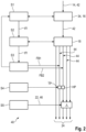
- FIG. 2 1 is a schematic block diagram of the sequence of a method 40 for frequency distortion 22 of the intermediate signal 14 FIG. 1 shown.
- the intermediate signal 14 forms the audio signal 42 , which acts as the input variable relevant to the method 40 .
- the audio signal 42 is used to check the frequency range in which acoustic feedback g from the output transducer 30 to the input transducer 8 of the hearing aid 2 is to be suppressed, and the frequency range in which there are also tonal signal components in the audio signal 42 that are present when the feedback is suppressed in the adaptive filter 34 may lead to artifacts.
- the check with regard to the acoustic feedback g to be suppressed can be carried out by the adaptive filter 34, with regard to the tonality of the signal components preferably by the signal processor 16.
- a first target frequency tf1 is then defined as a function of the results of these checks.
- the target frequency tf1 is determined in particular as the minimum frequency above which a frequency distortion is required for an effective suppression of the acoustic feedback.
- Step S2 the audio signal 42 is now divided into individual frequency bands in a filter bank 18 .
- Step S2 can also include further sub-steps, such as frequency-band-dependent processing of the signal components 44 in the frequency bands generated, which, however, do not impair the course of the method 40 per se.
- a first frequency band FB1 is now determined on the basis of the first target frequency tf1.
- the first frequency band FB1 is given here as that frequency band whose upper band limit frequency is defined by the band limit frequency immediately below the first target frequency tf1 is formed, the upper band limit frequency being given by that frequency at which the magnitude frequency response of the first frequency band is equal to the magnitude frequency response of the frequency band immediately above the first frequency band FB1.
- the frequency band immediately above the first frequency band FB1 is set as the second frequency band FB2.
- a low-pass filter TP is placed over the first frequency band FB1 at its band limit frequency to the second frequency band FB2, and a high-pass filter HP is placed over the second frequency band FB2 at the same band limit frequency.
- this further reduces the overlap between the first frequency band FB1 and the second frequency band FB2 than is provided by the filter bank 18, and on the other hand, the band limit frequency can easily be shifted to the first target frequency tf1 to be shifted towards.
- step S5 frequency distortion 22 in the form of a frequency shift 46 by a time-constant amount ⁇ is now applied to the signal components 44 in all frequency bands from the second frequency band FB2 upwards, while the signal components 44 remain unchanged in all frequency bands from the first frequency band FB1 downwards , and thus the frequency-distorted signal 24 is generated.
- the method 40 also returns to step S1 with the specification of the first frequency band FB1, and updates the first target frequency continuously, periodically or event-controlled in order to, in the event of a significant change in the acoustic feedback g, which results in the first target frequency tf1 being outside the first Frequency band FB1 is to determine a third frequency band FB3, which takes the place of the first frequency band FB1 to continue the method 40 analogously.
- the frequency response of a filter bank 18 is plotted against a frequency f.
- the individual frequency bands FB have a non-negligible overlap OV with the respectively adjacent frequency band, where two immediately adjacent frequency bands define a band limit frequency fL0 to fL3, which is given by that frequency at which the magnitude frequency response of the two adjacent frequency bands is the same.
- the first target frequency tf1 is now specified, and on the basis of this the first frequency band FB1 is determined as that frequency band whose upper band limit frequency fL1 is formed by the band limit frequency immediately below the first target frequency tf1.
- a low-pass filter TP is placed over the first frequency band FB1 at the upper band limit frequency fL1
- a high-pass filter HP is placed over the second frequency band FB2 at the same band limit frequency fL1, which therefore limits the second frequency band FB2 downwards.
- only one complex-valued zero (filter order 1) is preferably inserted.
- the signal components of the audio signal 42 in the frequency bands above the upper band limit frequency fL1 of the first frequency band FB1, ie in the frequency bands from FB2 upwards, are then shifted by a constant amount.
- the first target frequency tf1 is updated according to a second target frequency tf2 adapted to the change. It is now checked whether the second target frequency tf2 still corresponds to the band limit frequency fL1 between the first frequency band FB1 and the second frequency band FB2, i.e. whether the band limit frequency fL1 also forms the band limit frequency immediately below the second target frequency tf2. In that case, the frequency shift can continue to be applied unchanged to the signal components, preferably of all frequency bands from the second frequency band FB2 upwards (shaded area). preferably applied to the signal components of all frequency bands from the second frequency band FB2 upwards (shaded area).
- the second target frequency is now above the band limit frequency fL3, which limits a frequency band that differs from the first frequency band at the top to the immediately adjacent frequency band.
- the frequency band limited from above by the band limit frequency fL3 is now defined as the third frequency band FB3, and now the frequency shift for signal components preferably of all frequency bands above and excluding the third frequency band FB3 in the manner already described, in particular using appropriate high-pass or low-pass filters on the Band cutoff frequency fL3 (crosshatched area).
- FIG. 4 is the magnitude frequency response of the first frequency band FB1 and of the second frequency band FB2 FIG. 3 plotted at the band limit frequency fL1 against a frequency f.
- the dotted lines each show the absolute frequency response of the frequency bands FB1, FB2, as specified by the higher-level filter bank in the range of the band limit frequency fL1.
- the band limit frequency fL1 can also be shifted slightly to an adapted band limit frequency fL1', for example in the direction of the first target frequency.
Landscapes
- Engineering & Computer Science (AREA)
- Health & Medical Sciences (AREA)
- Physics & Mathematics (AREA)
- Acoustics & Sound (AREA)
- Signal Processing (AREA)
- General Health & Medical Sciences (AREA)
- Otolaryngology (AREA)
- Neurosurgery (AREA)
- Computational Linguistics (AREA)
- Quality & Reliability (AREA)
- Audiology, Speech & Language Pathology (AREA)
- Human Computer Interaction (AREA)
- Multimedia (AREA)
- Tone Control, Compression And Expansion, Limiting Amplitude (AREA)
- Circuit For Audible Band Transducer (AREA)
- Amplifiers (AREA)
Applications Claiming Priority (1)
| Application Number | Priority Date | Filing Date | Title |
|---|---|---|---|
| DE102017203631.1A DE102017203631B3 (de) | 2017-03-06 | 2017-03-06 | Verfahren zur Frequenzverzerrung eines Audiosignals |
Publications (2)
| Publication Number | Publication Date |
|---|---|
| EP3373601A1 EP3373601A1 (de) | 2018-09-12 |
| EP3373601B1 true EP3373601B1 (de) | 2023-05-31 |
Family
ID=61094356
Family Applications (1)
| Application Number | Title | Priority Date | Filing Date |
|---|---|---|---|
| EP18154220.0A Active EP3373601B1 (de) | 2017-03-06 | 2018-01-30 | Verfahren zur frequenzverzerrung eines audiosignals sowie ein hörgerät zum ausführen dieses verfahrens |
Country Status (6)
| Country | Link |
|---|---|
| US (1) | US10397712B2 (da) |
| EP (1) | EP3373601B1 (da) |
| JP (1) | JP6622830B2 (da) |
| CN (1) | CN108540907B (da) |
| DE (1) | DE102017203631B3 (da) |
| DK (1) | DK3373601T3 (da) |
Families Citing this family (1)
| Publication number | Priority date | Publication date | Assignee | Title |
|---|---|---|---|---|
| DK3783919T3 (da) * | 2019-08-22 | 2023-05-15 | Sonova Ag | Justering af diskantforstærkning af høreapparat |
Family Cites Families (8)
| Publication number | Priority date | Publication date | Assignee | Title |
|---|---|---|---|---|
| JP2005094265A (ja) * | 2003-09-16 | 2005-04-07 | Victor Co Of Japan Ltd | オーディオ再生装置 |
| DE102009018812B4 (de) * | 2009-04-24 | 2015-05-28 | Siemens Medical Instruments Pte. Ltd. | Verfahren zum Betrieb einer Hörvorrichtung und Hörvorrichtung mit einer Frequenzweiche |
| CN102264022B (zh) | 2010-04-08 | 2014-03-12 | Gn瑞声达公司 | 助听器的稳定性改进 |
| JP2014204213A (ja) | 2013-04-03 | 2014-10-27 | パイオニア株式会社 | デジタルフィルタ及びフィルタ特性変更方法 |
| EP2988529B1 (de) * | 2014-08-20 | 2019-12-04 | Sivantos Pte. Ltd. | Adaptive teilungsfrequenz in hörhilfegeräten |
| DE102015204010B4 (de) * | 2015-03-05 | 2016-12-15 | Sivantos Pte. Ltd. | Verfahren zur Unterdrückung eines Störgeräusches in einem akustischen System |
| DE102015204253B4 (de) | 2015-03-10 | 2016-11-10 | Sivantos Pte. Ltd. | Verfahren zur frequenzabhängigen Rauschunterdrückung eines Eingangssignals sowie Hörgerät |
| DE102015216822B4 (de) * | 2015-09-02 | 2017-07-06 | Sivantos Pte. Ltd. | Verfahren zur Unterdrückung einer Rückkopplung in einem Hörgerät |
-
2017
- 2017-03-06 DE DE102017203631.1A patent/DE102017203631B3/de active Active
-
2018
- 2018-01-30 DK DK18154220.0T patent/DK3373601T3/da active
- 2018-01-30 EP EP18154220.0A patent/EP3373601B1/de active Active
- 2018-02-26 US US15/904,479 patent/US10397712B2/en active Active
- 2018-03-05 CN CN201810178354.3A patent/CN108540907B/zh active Active
- 2018-03-06 JP JP2018039292A patent/JP6622830B2/ja active Active
Also Published As
| Publication number | Publication date |
|---|---|
| CN108540907A (zh) | 2018-09-14 |
| JP6622830B2 (ja) | 2019-12-18 |
| JP2018148562A (ja) | 2018-09-20 |
| EP3373601A1 (de) | 2018-09-12 |
| US10397712B2 (en) | 2019-08-27 |
| DE102017203631B3 (de) | 2018-05-17 |
| US20180255407A1 (en) | 2018-09-06 |
| CN108540907B (zh) | 2020-09-01 |
| DK3373601T3 (da) | 2023-08-28 |
Similar Documents
| Publication | Publication Date | Title |
|---|---|---|
| EP1853089B1 (de) | Verfahren zum Unterdrücken von Rückkopplungen und zur Spektralerweiterung bei Hörvorrichtungen | |
| EP2244491B1 (de) | Verfahren zum Betrieb einer Hörvorrichtung und Hörvorrichtung mit einer Frequenzweiche | |
| EP3197181B1 (de) | Verfahren zur reduktion der latenzzeit einer filterbank zur filterung eines audiosignals sowie verfahren zum latenzarmen betrieb eines hörsystems | |
| EP3139633A1 (de) | Verfahren zur unterdrückung einer rückkopplung in einem hörgerät | |
| DE102019123971A1 (de) | Aktive lärmkompensation | |
| EP3565270B1 (de) | Verfahren zur rauschunterdrückung in einem audiosignal | |
| EP2360945B1 (de) | Hörgerät mit Frequenzverschiebung und zugehöriges Verfahren | |
| EP2276272B1 (de) | Hörvorrichtung und Verfahren zur Unterdrückung von Rückkopplungen | |
| EP3355592B1 (de) | Verfahren zum betrieb eines binauralen hörgerätesystems | |
| EP3373599B1 (de) | Verfahren zur frequenzverzerrung eines audiosignals und nach diesem verfahren arbeitende hörvorrichtung | |
| EP1406469B1 (de) | Rückkopplungskompensator in einem akustischen Verstärkungssystem, Hörhilfsgerät, Verfahren zur Rückkopplungskompensation und Anwendung des Verfahrens in einem Hörhilfsgerät | |
| EP3373601B1 (de) | Verfahren zur frequenzverzerrung eines audiosignals sowie ein hörgerät zum ausführen dieses verfahrens | |
| DE102018207780B3 (de) | Verfahren zum Betrieb eines Hörgerätes | |
| EP3340656B1 (de) | Verfahren zum betrieb eines hörgerätes | |
| DE10310580A1 (de) | Vorrichtung und Verfahren zur Adaption von Hörgerätemikrofonen | |
| DE102006047986A1 (de) | Verarbeitung eines Eingangssignals in einer Hörhilfe | |
| EP4109929B1 (de) | Verfahren zur direktionalen signalverarbeitung von signalen einer mikrofonanordnung | |
| DE102019111150A1 (de) | Audioanlage und Verfahren zum Steuern einer Audioanlage | |
| EP1351550A1 (de) | Verfahren zur Anpassung einer Signalverstärkung in einem Hörgerät sowie ein Hörgerät | |
| DE4445983C2 (de) | Verfahren zur Rauschunterdrückung und Vorrichtungen zur Durchführung der Verfahren | |
| EP1653773A2 (de) | Verfahren zum Betrieb eines Hörgerätes sowie ein Hörgerät | |
| WO2007036443A1 (de) | Verfahren zur aktiven geräuschverminderung und eine vorrichtung zur durchführung des verfahrens | |
| EP4664931A1 (de) | Verfahren zur rauschunterdrückung in einem hörgerät | |
| DE102007021166A1 (de) | Verfahren zur adaptiven Dynamikerweiterung von Analog- zu Digitalumsetzern |
Legal Events
| Date | Code | Title | Description |
|---|---|---|---|
| PUAI | Public reference made under article 153(3) epc to a published international application that has entered the european phase |
Free format text: ORIGINAL CODE: 0009012 |
|
| STAA | Information on the status of an ep patent application or granted ep patent |
Free format text: STATUS: THE APPLICATION HAS BEEN PUBLISHED |
|
| AK | Designated contracting states |
Kind code of ref document: A1 Designated state(s): AL AT BE BG CH CY CZ DE DK EE ES FI FR GB GR HR HU IE IS IT LI LT LU LV MC MK MT NL NO PL PT RO RS SE SI SK SM TR |
|
| AX | Request for extension of the european patent |
Extension state: BA ME |
|
| STAA | Information on the status of an ep patent application or granted ep patent |
Free format text: STATUS: REQUEST FOR EXAMINATION WAS MADE |
|
| 17P | Request for examination filed |
Effective date: 20190312 |
|
| RBV | Designated contracting states (corrected) |
Designated state(s): AL AT BE BG CH CY CZ DE DK EE ES FI FR GB GR HR HU IE IS IT LI LT LU LV MC MK MT NL NO PL PT RO RS SE SI SK SM TR |
|
| STAA | Information on the status of an ep patent application or granted ep patent |
Free format text: STATUS: EXAMINATION IS IN PROGRESS |
|
| 17Q | First examination report despatched |
Effective date: 20190531 |
|
| GRAP | Despatch of communication of intention to grant a patent |
Free format text: ORIGINAL CODE: EPIDOSNIGR1 |
|
| STAA | Information on the status of an ep patent application or granted ep patent |
Free format text: STATUS: GRANT OF PATENT IS INTENDED |
|
| RIC1 | Information provided on ipc code assigned before grant |
Ipc: H04R 27/00 20060101ALN20221202BHEP Ipc: H04R 25/00 20060101AFI20221202BHEP |
|
| INTG | Intention to grant announced |
Effective date: 20221219 |
|
| GRAS | Grant fee paid |
Free format text: ORIGINAL CODE: EPIDOSNIGR3 |
|
| GRAA | (expected) grant |
Free format text: ORIGINAL CODE: 0009210 |
|
| STAA | Information on the status of an ep patent application or granted ep patent |
Free format text: STATUS: THE PATENT HAS BEEN GRANTED |
|
| RBV | Designated contracting states (corrected) |
Designated state(s): AL AT BE BG CH CY CZ DK EE ES FI FR GB GR HR HU IE IS IT LI LT LU LV MC MK MT NL NO PL PT RO RS SE SI SK SM TR |
|
| REG | Reference to a national code |
Ref country code: DE Ref legal event code: R108 |
|
| AK | Designated contracting states |
Kind code of ref document: B1 Designated state(s): AL AT BE BG CH CY CZ DK EE ES FI FR GB GR HR HU IE IS IT LI LT LU LV MC MK MT NL NO PL PT RO RS SE SI SK SM TR |
|
| REG | Reference to a national code |
Ref country code: GB Ref legal event code: FG4D Free format text: NOT ENGLISH Ref country code: CH Ref legal event code: EP |
|
| REG | Reference to a national code |
Ref country code: AT Ref legal event code: REF Ref document number: 1571730 Country of ref document: AT Kind code of ref document: T Effective date: 20230615 |
|
| REG | Reference to a national code |
Ref country code: IE Ref legal event code: FG4D Free format text: LANGUAGE OF EP DOCUMENT: GERMAN |
|
| REG | Reference to a national code |
Ref country code: DK Ref legal event code: T3 Effective date: 20230824 |
|
| REG | Reference to a national code |
Ref country code: LT Ref legal event code: MG9D |
|
| REG | Reference to a national code |
Ref country code: NL Ref legal event code: MP Effective date: 20230531 |
|
| PG25 | Lapsed in a contracting state [announced via postgrant information from national office to epo] |
Ref country code: SE Free format text: LAPSE BECAUSE OF FAILURE TO SUBMIT A TRANSLATION OF THE DESCRIPTION OR TO PAY THE FEE WITHIN THE PRESCRIBED TIME-LIMIT Effective date: 20230531 Ref country code: NO Free format text: LAPSE BECAUSE OF FAILURE TO SUBMIT A TRANSLATION OF THE DESCRIPTION OR TO PAY THE FEE WITHIN THE PRESCRIBED TIME-LIMIT Effective date: 20230831 Ref country code: ES Free format text: LAPSE BECAUSE OF FAILURE TO SUBMIT A TRANSLATION OF THE DESCRIPTION OR TO PAY THE FEE WITHIN THE PRESCRIBED TIME-LIMIT Effective date: 20230531 |
|
| PG25 | Lapsed in a contracting state [announced via postgrant information from national office to epo] |
Ref country code: RS Free format text: LAPSE BECAUSE OF FAILURE TO SUBMIT A TRANSLATION OF THE DESCRIPTION OR TO PAY THE FEE WITHIN THE PRESCRIBED TIME-LIMIT Effective date: 20230531 Ref country code: PL Free format text: LAPSE BECAUSE OF FAILURE TO SUBMIT A TRANSLATION OF THE DESCRIPTION OR TO PAY THE FEE WITHIN THE PRESCRIBED TIME-LIMIT Effective date: 20230531 Ref country code: NL Free format text: LAPSE BECAUSE OF FAILURE TO SUBMIT A TRANSLATION OF THE DESCRIPTION OR TO PAY THE FEE WITHIN THE PRESCRIBED TIME-LIMIT Effective date: 20230531 Ref country code: LV Free format text: LAPSE BECAUSE OF FAILURE TO SUBMIT A TRANSLATION OF THE DESCRIPTION OR TO PAY THE FEE WITHIN THE PRESCRIBED TIME-LIMIT Effective date: 20230531 Ref country code: LT Free format text: LAPSE BECAUSE OF FAILURE TO SUBMIT A TRANSLATION OF THE DESCRIPTION OR TO PAY THE FEE WITHIN THE PRESCRIBED TIME-LIMIT Effective date: 20230531 Ref country code: IS Free format text: LAPSE BECAUSE OF FAILURE TO SUBMIT A TRANSLATION OF THE DESCRIPTION OR TO PAY THE FEE WITHIN THE PRESCRIBED TIME-LIMIT Effective date: 20230930 Ref country code: HR Free format text: LAPSE BECAUSE OF FAILURE TO SUBMIT A TRANSLATION OF THE DESCRIPTION OR TO PAY THE FEE WITHIN THE PRESCRIBED TIME-LIMIT Effective date: 20230531 Ref country code: GR Free format text: LAPSE BECAUSE OF FAILURE TO SUBMIT A TRANSLATION OF THE DESCRIPTION OR TO PAY THE FEE WITHIN THE PRESCRIBED TIME-LIMIT Effective date: 20230901 |
|
| PG25 | Lapsed in a contracting state [announced via postgrant information from national office to epo] |
Ref country code: FI Free format text: LAPSE BECAUSE OF FAILURE TO SUBMIT A TRANSLATION OF THE DESCRIPTION OR TO PAY THE FEE WITHIN THE PRESCRIBED TIME-LIMIT Effective date: 20230531 |
|
| PG25 | Lapsed in a contracting state [announced via postgrant information from national office to epo] |
Ref country code: SK Free format text: LAPSE BECAUSE OF FAILURE TO SUBMIT A TRANSLATION OF THE DESCRIPTION OR TO PAY THE FEE WITHIN THE PRESCRIBED TIME-LIMIT Effective date: 20230531 |
|
| PG25 | Lapsed in a contracting state [announced via postgrant information from national office to epo] |
Ref country code: SM Free format text: LAPSE BECAUSE OF FAILURE TO SUBMIT A TRANSLATION OF THE DESCRIPTION OR TO PAY THE FEE WITHIN THE PRESCRIBED TIME-LIMIT Effective date: 20230531 Ref country code: SK Free format text: LAPSE BECAUSE OF FAILURE TO SUBMIT A TRANSLATION OF THE DESCRIPTION OR TO PAY THE FEE WITHIN THE PRESCRIBED TIME-LIMIT Effective date: 20230531 Ref country code: RO Free format text: LAPSE BECAUSE OF FAILURE TO SUBMIT A TRANSLATION OF THE DESCRIPTION OR TO PAY THE FEE WITHIN THE PRESCRIBED TIME-LIMIT Effective date: 20230531 Ref country code: PT Free format text: LAPSE BECAUSE OF FAILURE TO SUBMIT A TRANSLATION OF THE DESCRIPTION OR TO PAY THE FEE WITHIN THE PRESCRIBED TIME-LIMIT Effective date: 20231002 Ref country code: EE Free format text: LAPSE BECAUSE OF FAILURE TO SUBMIT A TRANSLATION OF THE DESCRIPTION OR TO PAY THE FEE WITHIN THE PRESCRIBED TIME-LIMIT Effective date: 20230531 Ref country code: CZ Free format text: LAPSE BECAUSE OF FAILURE TO SUBMIT A TRANSLATION OF THE DESCRIPTION OR TO PAY THE FEE WITHIN THE PRESCRIBED TIME-LIMIT Effective date: 20230531 |
|
| PLBE | No opposition filed within time limit |
Free format text: ORIGINAL CODE: 0009261 |
|
| STAA | Information on the status of an ep patent application or granted ep patent |
Free format text: STATUS: NO OPPOSITION FILED WITHIN TIME LIMIT |
|
| PG25 | Lapsed in a contracting state [announced via postgrant information from national office to epo] |
Ref country code: SI Free format text: LAPSE BECAUSE OF FAILURE TO SUBMIT A TRANSLATION OF THE DESCRIPTION OR TO PAY THE FEE WITHIN THE PRESCRIBED TIME-LIMIT Effective date: 20230531 |
|
| 26N | No opposition filed |
Effective date: 20240301 |
|
| PG25 | Lapsed in a contracting state [announced via postgrant information from national office to epo] |
Ref country code: SI Free format text: LAPSE BECAUSE OF FAILURE TO SUBMIT A TRANSLATION OF THE DESCRIPTION OR TO PAY THE FEE WITHIN THE PRESCRIBED TIME-LIMIT Effective date: 20230531 Ref country code: IT Free format text: LAPSE BECAUSE OF FAILURE TO SUBMIT A TRANSLATION OF THE DESCRIPTION OR TO PAY THE FEE WITHIN THE PRESCRIBED TIME-LIMIT Effective date: 20230531 |
|
| PG25 | Lapsed in a contracting state [announced via postgrant information from national office to epo] |
Ref country code: MC Free format text: LAPSE BECAUSE OF FAILURE TO SUBMIT A TRANSLATION OF THE DESCRIPTION OR TO PAY THE FEE WITHIN THE PRESCRIBED TIME-LIMIT Effective date: 20230531 |
|
| PG25 | Lapsed in a contracting state [announced via postgrant information from national office to epo] |
Ref country code: MC Free format text: LAPSE BECAUSE OF FAILURE TO SUBMIT A TRANSLATION OF THE DESCRIPTION OR TO PAY THE FEE WITHIN THE PRESCRIBED TIME-LIMIT Effective date: 20230531 |
|
| PG25 | Lapsed in a contracting state [announced via postgrant information from national office to epo] |
Ref country code: LU Free format text: LAPSE BECAUSE OF NON-PAYMENT OF DUE FEES Effective date: 20240130 |
|
| PG25 | Lapsed in a contracting state [announced via postgrant information from national office to epo] |
Ref country code: LU Free format text: LAPSE BECAUSE OF NON-PAYMENT OF DUE FEES Effective date: 20240130 |
|
| PG25 | Lapsed in a contracting state [announced via postgrant information from national office to epo] |
Ref country code: BE Free format text: LAPSE BECAUSE OF NON-PAYMENT OF DUE FEES Effective date: 20240131 |
|
| PG25 | Lapsed in a contracting state [announced via postgrant information from national office to epo] |
Ref country code: BE Free format text: LAPSE BECAUSE OF NON-PAYMENT OF DUE FEES Effective date: 20240131 |
|
| REG | Reference to a national code |
Ref country code: BE Ref legal event code: MM Effective date: 20240131 |
|
| PG25 | Lapsed in a contracting state [announced via postgrant information from national office to epo] |
Ref country code: BG Free format text: LAPSE BECAUSE OF FAILURE TO SUBMIT A TRANSLATION OF THE DESCRIPTION OR TO PAY THE FEE WITHIN THE PRESCRIBED TIME-LIMIT Effective date: 20230531 |
|
| PG25 | Lapsed in a contracting state [announced via postgrant information from national office to epo] |
Ref country code: BG Free format text: LAPSE BECAUSE OF FAILURE TO SUBMIT A TRANSLATION OF THE DESCRIPTION OR TO PAY THE FEE WITHIN THE PRESCRIBED TIME-LIMIT Effective date: 20230531 |
|
| PG25 | Lapsed in a contracting state [announced via postgrant information from national office to epo] |
Ref country code: IE Free format text: LAPSE BECAUSE OF NON-PAYMENT OF DUE FEES Effective date: 20240130 |
|
| PG25 | Lapsed in a contracting state [announced via postgrant information from national office to epo] |
Ref country code: IE Free format text: LAPSE BECAUSE OF NON-PAYMENT OF DUE FEES Effective date: 20240130 |
|
| REG | Reference to a national code |
Ref country code: AT Ref legal event code: MM01 Ref document number: 1571730 Country of ref document: AT Kind code of ref document: T Effective date: 20240130 |
|
| PG25 | Lapsed in a contracting state [announced via postgrant information from national office to epo] |
Ref country code: AT Free format text: LAPSE BECAUSE OF NON-PAYMENT OF DUE FEES Effective date: 20240130 |
|
| PG25 | Lapsed in a contracting state [announced via postgrant information from national office to epo] |
Ref country code: CY Free format text: LAPSE BECAUSE OF FAILURE TO SUBMIT A TRANSLATION OF THE DESCRIPTION OR TO PAY THE FEE WITHIN THE PRESCRIBED TIME-LIMIT; INVALID AB INITIO Effective date: 20180130 |
|
| PG25 | Lapsed in a contracting state [announced via postgrant information from national office to epo] |
Ref country code: HU Free format text: LAPSE BECAUSE OF FAILURE TO SUBMIT A TRANSLATION OF THE DESCRIPTION OR TO PAY THE FEE WITHIN THE PRESCRIBED TIME-LIMIT; INVALID AB INITIO Effective date: 20180130 |
|
| PG25 | Lapsed in a contracting state [announced via postgrant information from national office to epo] |
Ref country code: TR Free format text: LAPSE BECAUSE OF FAILURE TO SUBMIT A TRANSLATION OF THE DESCRIPTION OR TO PAY THE FEE WITHIN THE PRESCRIBED TIME-LIMIT Effective date: 20230531 |
|
| PGFP | Annual fee paid to national office [announced via postgrant information from national office to epo] |
Ref country code: GB Payment date: 20251219 Year of fee payment: 9 |
|
| PGFP | Annual fee paid to national office [announced via postgrant information from national office to epo] |
Ref country code: DK Payment date: 20251217 Year of fee payment: 9 |
|
| PGFP | Annual fee paid to national office [announced via postgrant information from national office to epo] |
Ref country code: FR Payment date: 20251217 Year of fee payment: 9 |
|
| REG | Reference to a national code |
Ref country code: CH Ref legal event code: U11 Free format text: ST27 STATUS EVENT CODE: U-0-0-U10-U11 (AS PROVIDED BY THE NATIONAL OFFICE) Effective date: 20260201 |
|
| PGFP | Annual fee paid to national office [announced via postgrant information from national office to epo] |
Ref country code: CH Payment date: 20260201 Year of fee payment: 9 |