EP3373440B1 - Piezomotorisch angetriebene vorrichtung - Google Patents
Piezomotorisch angetriebene vorrichtung Download PDFInfo
- Publication number
- EP3373440B1 EP3373440B1 EP18160260.8A EP18160260A EP3373440B1 EP 3373440 B1 EP3373440 B1 EP 3373440B1 EP 18160260 A EP18160260 A EP 18160260A EP 3373440 B1 EP3373440 B1 EP 3373440B1
- Authority
- EP
- European Patent Office
- Prior art keywords
- gear rack
- actuators
- piezo
- tooth
- actuator
- Prior art date
- Legal status (The legal status is an assumption and is not a legal conclusion. Google has not performed a legal analysis and makes no representation as to the accuracy of the status listed.)
- Active
Links
Images

Classifications
-
- H—ELECTRICITY
- H02—GENERATION; CONVERSION OR DISTRIBUTION OF ELECTRIC POWER
- H02N—ELECTRIC MACHINES NOT OTHERWISE PROVIDED FOR
- H02N2/00—Electric machines in general using piezoelectric effect, electrostriction or magnetostriction
- H02N2/02—Electric machines in general using piezoelectric effect, electrostriction or magnetostriction producing linear motion, e.g. actuators; Linear positioners ; Linear motors
-
- H—ELECTRICITY
- H02—GENERATION; CONVERSION OR DISTRIBUTION OF ELECTRIC POWER
- H02N—ELECTRIC MACHINES NOT OTHERWISE PROVIDED FOR
- H02N2/00—Electric machines in general using piezoelectric effect, electrostriction or magnetostriction
- H02N2/02—Electric machines in general using piezoelectric effect, electrostriction or magnetostriction producing linear motion, e.g. actuators; Linear positioners ; Linear motors
- H02N2/04—Constructional details
- H02N2/043—Mechanical transmission means, e.g. for stroke amplification
-
- B—PERFORMING OPERATIONS; TRANSPORTING
- B06—GENERATING OR TRANSMITTING MECHANICAL VIBRATIONS IN GENERAL
- B06B—METHODS OR APPARATUS FOR GENERATING OR TRANSMITTING MECHANICAL VIBRATIONS OF INFRASONIC, SONIC, OR ULTRASONIC FREQUENCY, e.g. FOR PERFORMING MECHANICAL WORK IN GENERAL
- B06B1/00—Methods or apparatus for generating mechanical vibrations of infrasonic, sonic, or ultrasonic frequency
- B06B1/02—Methods or apparatus for generating mechanical vibrations of infrasonic, sonic, or ultrasonic frequency making use of electrical energy
- B06B1/06—Methods or apparatus for generating mechanical vibrations of infrasonic, sonic, or ultrasonic frequency making use of electrical energy operating with piezoelectric effect or with electrostriction
- B06B1/0603—Methods or apparatus for generating mechanical vibrations of infrasonic, sonic, or ultrasonic frequency making use of electrical energy operating with piezoelectric effect or with electrostriction using a piezoelectric bender, e.g. bimorph
-
- H—ELECTRICITY
- H02—GENERATION; CONVERSION OR DISTRIBUTION OF ELECTRIC POWER
- H02N—ELECTRIC MACHINES NOT OTHERWISE PROVIDED FOR
- H02N2/00—Electric machines in general using piezoelectric effect, electrostriction or magnetostriction
- H02N2/02—Electric machines in general using piezoelectric effect, electrostriction or magnetostriction producing linear motion, e.g. actuators; Linear positioners ; Linear motors
- H02N2/021—Electric machines in general using piezoelectric effect, electrostriction or magnetostriction producing linear motion, e.g. actuators; Linear positioners ; Linear motors using intermittent driving, e.g. step motors, piezoleg motors
-
- H—ELECTRICITY
- H02—GENERATION; CONVERSION OR DISTRIBUTION OF ELECTRIC POWER
- H02N—ELECTRIC MACHINES NOT OTHERWISE PROVIDED FOR
- H02N2/00—Electric machines in general using piezoelectric effect, electrostriction or magnetostriction
- H02N2/02—Electric machines in general using piezoelectric effect, electrostriction or magnetostriction producing linear motion, e.g. actuators; Linear positioners ; Linear motors
- H02N2/06—Drive circuits; Control arrangements or methods
Definitions
- the field of the invention relates to a piezo motor driven device.
- Piezo or piezoelectric motors are suitable for such purposes for example to drive an ultrasonic nozzle, for ultrafine focusing of optical assemblies, for scanning probe microscopies with atomic resolution, to point sensors at the right location, move samples, or for fluid dispensing on a small scale.
- Piezo motors make use of the converse piezoelectric effect whereby the piezoelectric material produces acoustic or ultrasonic vibrations for producing a motion.
- piezo motor principles are known.
- One drive technique is to use piezo material to push a stator.
- These piezo motors are basically stepping motors, with each step comprising either two or three actions, based on the locking type.
- piezo drive technique uses piezoelectric elements that are bonded orthogonally to a nut and their ultrasonic vibrations rotate and translate a central lead screw. This is called a piezo direct drive motor.
- the direct drive piezo motor uses continuous ultrasonic vibrations to provide movement.
- a two-channel sinusoidal or square wave is applied to the piezoelectric elements at an ultrasonic frequency of about 40kHz to 200kHz, matching the first bending resonant frequency of the threaded tube. This creates orbital motion which drives the screw.
- the non-powered behavior of a piezo motor is one of two options: normally locked or normally free.
- normally locked motor When no power is being applied to a normally locked motor, the spindle or carriage for rotary or linear types respectively, will not move under external force.
- normally free motor the spindle or carriage will move freely under external force.
- both locking groups are powered at rest, a normally free motor will resist external force without providing any motive force.
- a combination of mechanical latches and crystals could be used, but this would restrict the maximum stepping rate of the motor.
- U.S. Patent Application Publication No. 2005/0005722 A1 discloses an example of a piezoelectric motor drive having a longitudinal gear rack.
- This application refers to a positioning device that includes a movable body; a position detection unit detecting a position of the movable body; a first and a second vibratory actuator controlled in accordance with a detection output from the position detection unit; a first transmission mechanism comprising a first gear wheel and a first rack engaging the first gear wheel, the first transmission mechanism transmitting a driving force of the first vibratory actuator to the movable body; and a second transmission mechanism comprising a second gear wheel and a second rack engaging the second gear wheel, the second transmission mechanism transmitting a driving force of the second vibratory actuator to the movable body.
- An engaging position of the first gear wheel with the first rack is different from an engaging position of the second gear wheel with the second rack.
- Japanese Patent Application Publication No. 2008172967 A discloses another example of a piezoelectric motor drive having a longitudinal gear rack.
- This application discloses a guide part that includes guide faces, which extend along the moving direction so as to receive a driving force when an operation part generates a driving force, and a bottom part that extends along the moving direction so as to support the operation part while being in contact therewith regardless of a driving force generated by the operation part.
- the operation part according to this document has tooth parts in contact with the guide faces.
- the operation part includes a pair of moving elements, which respectively has a ratchet mechanism that slides in one of the extending directions of the guide faces and engages in the other of the extending directions, an ultrasonic actuator for generating a driving force, and a driving force transmission mechanism that is driven by the ultrasonic actuator so as to expand/reduce an interval between the pair of moving elements in the extending direction.
- a further example of a linear motor comprising a gear rack can be found in SU 764018 which includes a ratchet on the gear wheel attached to a vibrating beam and engaging with a linear gear track.
- the prior art piezoelectric motor principles are all based on motion by sliding or static friction between a stationary part, the stator and a moved part, the rotor.
- the disadvantage of the prior art piezo motors with a frictionally engaged drive mechanism is, that every single step or movement of an actuator as well as the self-locking of the motor are strongly influenced by environmental conditions and physical factors such as temperature, surface quality, pretension force, air humidity and others.
- the prior art motors compensate for the effect of such factors with a sufficient or over dimensioned pretension force and are driven in a closed loop drive control.
- the operation of the prior art motors is thus very complex and expensive.
- a piezoelectric motor that avoids step losses or undefined step sizes caused by environmental conditions like e.g. temperature, surface quality, air humidity, but can be permanently locked or unlocked in an unpowered state.
- the instant invention provides a piezo motor driven device comprising a movable gear rack with a toothed structure on two opposite longitudinal sides and at least three actuators each having a tooth, wherein the at least three actuators are arranged in a manner that at least one actuator is present on each longitudinal sides of the gear rack and each actuator is connected with an end of a piezo bender.
- each tooth of the at least three actuators may have a size to engage into the toothed structure of the gear rack.
- a tooth of the gear rack has a width X and a tooth of an actuator is staggered in a distance X/n within a clearance between two teeth of the gear rack, wherein n is an integer starting with 3 representing the number of actuators, so that each tooth of an actuator is located at a different position within the clearance between two teeth of the gear rack.
- Each of the at least three actuators may comprise a central part.
- the central part of a piezo motor driven device may provide in a further aspect for each of the at least three actuators being enclosed by an actuator arm having the tooth for engaging into the gear rack on one end and a spring-load mechanism located on the other end.
- the movable guide rack can be embedded into a guide rail and the gear rack may further be symmetrically toothed.
- Another aspect of the invention refers to a method for moving a gear rack with a piezo motor comprising the gear rack with a toothed structure on two opposite longitudinal sides and at least three actuators each having a tooth, wherein the at least three actuators are arranged on both longitudinal sides of the gear rack and each actuator is connected to an end of a piezo bender, comprising the steps of
- the gear rack may be moved linear by the above described method.
- the invention provides a piezo bender arranged within a form-locked drive mechanism avoiding step losses and undefined step sizes caused by environmental conditions such as temperature, surface quality and air humidity.
- a piezo bender generates a bending mode upon activation of a piezo element located at one end of the bending element of the piezo bender.
- piezo motor and piezo bender are used synonymously.
- the invented piezo motor principle works with at least three single actuators which are integrated into a form-locked drive mechanism.
- the described technology avoids step losses, undefined step sizes caused by environmental conditions like e.g. temperature, surface quality, air humidity.
- the invented motor can be configured to be permanently locked or to be permanently unlocked in an unpowered state. It is further possible to use the described piezo motor without an encoder, due to the form locked drive mechanism, even for positioning on a given time-speed ramp.
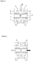
- Figure 1 shows a device 1 with a gear rack 5 and four actuators.
- the actuators have a central element 3 that is surrounded by one end of an actuator arm 30.
- the actuator arm 30 has on one end a spring load mechanism 33 that is connected with frame 35 in device 1.
- the opposite end of the actuator arm 30 surrounds the central element 3 and has further a tooth 4 arranged near its end for engaging into gears of gear rack 5.
- Gear rack 5 is located within guide rail 40 for guiding movement of gear rack 5 only in two directions.
- One end of bending element 2 of the piezo bender engages into central element 3, the opposite end is fixed by fixation of bending element 10. Bending of the bending element 2 by activation of the piezo element results in a movement of the central element 3 and thus teeth 4 towards gear rack 5.
- Gear rack 5 is moved by a sequentially activation of the piezo bender causing sequential engagement of teeth 4 into the teeth of gear rack 5.
- FIG. 2 shows a detailed depiction of the arrangement of four teeth 4 of the actuators on both sides of gear rack 5.
- Each tooth 4 is located at the end of actuator arm 30.
- One end of bending element 2 engages into central element 3. Bending the bending element 2 will result in a movement of teeth 4 towards gear rack 5 and engagement into the teeth of gear rack 5.
- the teeth of the gear rack 5 have width X and the actuator tooth 4 are staggered in a distance corresponding to X/4 in case of four actuators.
- the teeth of the actuator are thus located in different positions within the clearance between two teeth of gear rack. This correlation between the width X of gear teeth and staggering actuator teeth 4 causes a movement of gear rack 5 depending on the sequence of arranging the actuator's teeth in the clearance between the teeth of the gear rack.
Landscapes
- Engineering & Computer Science (AREA)
- Mechanical Engineering (AREA)
- General Electrical Machinery Utilizing Piezoelectricity, Electrostriction Or Magnetostriction (AREA)
Claims (9)
- Eine von einem Piezomotor angetriebene Vorrichtung, mit einer beweglichen Zahnstange mit einer Zahnstruktur an zwei gegenüberliegenden Längsseiten und mindestens drei Aktuatoren, die jeweils einen Zahn aufweisen, wobei die mindestens drei Aktuatoren so angeordnet sind, dass mindestens ein Aktuator an jeder Längsseite der Zahnstange vorhanden ist und jeder Aktuator mit einem Ende einer Piezo-Biegevorrichtung verbunden ist.
- Der Piezomotor nach Anspruch 1, wobei jeder Zahn der mindestens drei Aktuatoren eine Größe hat, um in die Zahnstruktur der Zahnstange einzugreifen.
- Der Piezomotor nach einem der Ansprüche 1 oder 2, wobei ein Zahn der Zahnstange eine Breite X hat und ein Zahn eines Aktuators in einem Abstand X/n innerhalb eines Zwischenraums zwischen zwei Zähnen der Zahnstange versetzt ist, wobei n eine ganze Zahl ist, die mit 3 beginnt und die Anzahl der Aktuatoren darstellt, so dass jeder Zahn eines Aktuators an einer anderen Position innerhalb des Zwischenraums zwischen zwei Zähnen der Zahnstange angeordnet ist.
- Der Piezomotor nach einem der Ansprüche 1 bis 3, wobei jeder der mindestens drei Aktoren einen zentralen Teil.
- Der Piezomotor nach einem der Ansprüche 1 bis 4, bei dem der Mittelteil jedes der mindestens drei Aktuatoren von einem Aktuatorarm umschlossen ist, der an einem Ende den Zahn zum Eingriff in die Zahnstange und am anderen Ende einen Federspannmechanismus aufweist.
- Der Piezomotor nach einem der Ansprüche 1 bis 5, bei dem die bewegliche Führungszahnstange in eine Führungsschiene eingebettet ist.
- Der Piezomotor nach einem der Ansprüche 1 bis 6, bei dem die Zahnstange symmetrisch verzahnt ist.
- Ein Verfahren zum Bewegen einer Zahnstange mit einem Piezomotor, der die Zahnstange mit einer Zahnstruktur an zwei gegenüberliegenden Längsseiten und mindestens drei Aktuatoren mit jeweils einem Zahn aufweist, wobei die mindestens drei Aktuatoren an beiden Längsseiten der Zahnstange angeordnet sind und jeder Aktuator mit einem Ende einer Piezo-Biegevorrichtung verbunden ist, mit den folgenden Schritten- sequentielles Betätigen des Piezo-Biegers,- die Zähne der mindestens drei Aktuatoren nacheinander und vertikal in die Zahnstruktur der Zahnstange eingreifen,- Bewegen der Zahnstange in eine Richtung, die von der Reihenfolge der Betätigung der mindestens drei Stellglieder abhängt.
- Das Verfahren nach Anspruch 8, wobei die Zahnstange linear bewegt wird.
Applications Claiming Priority (1)
| Application Number | Priority Date | Filing Date | Title |
|---|---|---|---|
| GB1703593.2A GB2560326A (en) | 2017-03-07 | 2017-03-07 | Piezo motor driven device |
Publications (2)
| Publication Number | Publication Date |
|---|---|
| EP3373440A1 EP3373440A1 (de) | 2018-09-12 |
| EP3373440B1 true EP3373440B1 (de) | 2020-11-11 |
Family
ID=58543886
Family Applications (1)
| Application Number | Title | Priority Date | Filing Date |
|---|---|---|---|
| EP18160260.8A Active EP3373440B1 (de) | 2017-03-07 | 2018-03-06 | Piezomotorisch angetriebene vorrichtung |
Country Status (3)
| Country | Link |
|---|---|
| US (1) | US11038441B2 (de) |
| EP (1) | EP3373440B1 (de) |
| GB (1) | GB2560326A (de) |
Families Citing this family (2)
| Publication number | Priority date | Publication date | Assignee | Title |
|---|---|---|---|---|
| US20220071279A1 (en) * | 2016-06-01 | 2022-03-10 | Dabble Ventures, Llc | Vibrating hookah and method of using same |
| CN110829881A (zh) * | 2019-07-25 | 2020-02-21 | 浙江师范大学 | 一种伞型爬行式压电驱动平台 |
Family Cites Families (8)
| Publication number | Priority date | Publication date | Assignee | Title |
|---|---|---|---|---|
| SU764018A1 (ru) * | 1978-12-18 | 1980-09-15 | Томский Ордена Октябрьской Революции И Ордена Трудового Красного Знамени Политехнический Институт Им. С.М.Кирова | Шаговый двигатель |
| US5049775A (en) * | 1988-09-30 | 1991-09-17 | Boston University | Integrated micromechanical piezoelectric motor |
| FR2794581B1 (fr) * | 1999-06-04 | 2001-09-07 | France Fa Norbert Beyrard | Dispositif d'actionnement comprenant au moins un moteur piezo-electrique et une piece mobile sous l'action dudit moteur piezo-electrique |
| DE69929947T2 (de) * | 1999-06-04 | 2006-10-19 | Norbert Beyrard France (Sarl) | Durch einen piezoelektrischen Motor angetriebener Schalter |
| JP4328575B2 (ja) * | 2003-07-08 | 2009-09-09 | キヤノン株式会社 | 振動型駆動装置を用いた位置決め機構 |
| JP2008172967A (ja) * | 2007-01-15 | 2008-07-24 | Seiko Epson Corp | 線状駆動装置 |
| JP2010187524A (ja) * | 2009-01-14 | 2010-08-26 | Seiko Epson Corp | 圧電駆動装置および電子機器 |
| DE102011001039A1 (de) * | 2011-03-02 | 2012-09-06 | Wittenstein Ag | Adaptives Getriebe |
-
2017
- 2017-03-07 GB GB1703593.2A patent/GB2560326A/en not_active Withdrawn
-
2018
- 2018-03-06 US US15/913,070 patent/US11038441B2/en active Active
- 2018-03-06 EP EP18160260.8A patent/EP3373440B1/de active Active
Non-Patent Citations (1)
| Title |
|---|
| None * |
Also Published As
| Publication number | Publication date |
|---|---|
| GB201703593D0 (en) | 2017-04-19 |
| US20180262128A1 (en) | 2018-09-13 |
| US11038441B2 (en) | 2021-06-15 |
| GB2560326A (en) | 2018-09-12 |
| EP3373440A1 (de) | 2018-09-12 |
Similar Documents
| Publication | Publication Date | Title |
|---|---|---|
| Peng et al. | A review of long range piezoelectric motors using frequency leveraged method | |
| Hunstig | Piezoelectric inertia motors—A critical review of history, concepts, design, applications, and perspectives | |
| EP3195463B1 (de) | Verstärkter piezoaktuator mit motorisierter verstellschraube | |
| US8520327B2 (en) | Optical adjustment mounts with piezoelectric inertia driver | |
| US9172313B2 (en) | Oscillatory wave drive unit and image stabilization device | |
| US20140026727A1 (en) | Microtome having a piezoelectric linear actuator | |
| US11038441B2 (en) | Piezo motor driven device | |
| CN112803829B (zh) | 摩擦非对称型惯性压电直线驱动装置与方法 | |
| EP1793432B1 (de) | Verfahren und Einrichtung für präzise und Hochlast-widerstandsfähige Bewegung | |
| US10663040B2 (en) | Method and precision nanopositioning apparatus with compact vertical and horizontal linear nanopositioning flexure stages for implementing enhanced nanopositioning performance | |
| JP5166545B2 (ja) | ステージ駆動装置 | |
| US11290030B2 (en) | Drive device and method for linear or rotary positioning | |
| JP4328575B2 (ja) | 振動型駆動装置を用いた位置決め機構 | |
| JP2009089517A (ja) | 超音波モータの駆動装置 | |
| JP6021559B2 (ja) | 振動型駆動装置及び撮像装置 | |
| JPH0714279B2 (ja) | リニアアクチュエータ | |
| GB2510027A (en) | A pipette with piezo motor | |
| CN107894644A (zh) | 机载光学镜头调焦机构 | |
| KR100876617B1 (ko) | 압전 구동기를 이용한 장행정 정밀 이송 장치 | |
| JP4976844B2 (ja) | 多自由度駆動装置および撮像装置 | |
| Müller et al. | Piezo-based, long-travel actuators for special environmental conditions | |
| CN107994804B (zh) | 一种超声驱动宏微复合运动平台 | |
| TW201304386A (zh) | 摩擦驅動致動器 | |
| Bardin et al. | Piezoactuators and piezomotors with nano-and micro-dimensional resolution for test and control equipment | |
| King | Application of mechanical amplifiers in piezoelectric actuators |
Legal Events
| Date | Code | Title | Description |
|---|---|---|---|
| PUAI | Public reference made under article 153(3) epc to a published international application that has entered the european phase |
Free format text: ORIGINAL CODE: 0009012 |
|
| STAA | Information on the status of an ep patent application or granted ep patent |
Free format text: STATUS: THE APPLICATION HAS BEEN PUBLISHED |
|
| AK | Designated contracting states |
Kind code of ref document: A1 Designated state(s): AL AT BE BG CH CY CZ DE DK EE ES FI FR GB GR HR HU IE IS IT LI LT LU LV MC MK MT NL NO PL PT RO RS SE SI SK SM TR |
|
| AX | Request for extension of the european patent |
Extension state: BA ME |
|
| STAA | Information on the status of an ep patent application or granted ep patent |
Free format text: STATUS: REQUEST FOR EXAMINATION WAS MADE |
|
| 17P | Request for examination filed |
Effective date: 20190312 |
|
| RAP1 | Party data changed (applicant data changed or rights of an application transferred) |
Owner name: STRATEC SE |
|
| RBV | Designated contracting states (corrected) |
Designated state(s): AL AT BE BG CH CY CZ DE DK EE ES FI FR GB GR HR HU IE IS IT LI LT LU LV MC MK MT NL NO PL PT RO RS SE SI SK SM TR |
|
| RIC1 | Information provided on ipc code assigned before grant |
Ipc: H02N 2/02 20060101ALI20200331BHEP Ipc: H02N 2/06 20060101ALI20200331BHEP Ipc: H02N 2/04 20060101AFI20200331BHEP |
|
| GRAP | Despatch of communication of intention to grant a patent |
Free format text: ORIGINAL CODE: EPIDOSNIGR1 |
|
| STAA | Information on the status of an ep patent application or granted ep patent |
Free format text: STATUS: GRANT OF PATENT IS INTENDED |
|
| INTG | Intention to grant announced |
Effective date: 20200602 |
|
| GRAS | Grant fee paid |
Free format text: ORIGINAL CODE: EPIDOSNIGR3 |
|
| GRAA | (expected) grant |
Free format text: ORIGINAL CODE: 0009210 |
|
| STAA | Information on the status of an ep patent application or granted ep patent |
Free format text: STATUS: THE PATENT HAS BEEN GRANTED |
|
| AK | Designated contracting states |
Kind code of ref document: B1 Designated state(s): AL AT BE BG CH CY CZ DE DK EE ES FI FR GB GR HR HU IE IS IT LI LT LU LV MC MK MT NL NO PL PT RO RS SE SI SK SM TR |
|
| REG | Reference to a national code |
Ref country code: GB Ref legal event code: FG4D |
|
| REG | Reference to a national code |
Ref country code: CH Ref legal event code: EP |
|
| REG | Reference to a national code |
Ref country code: AT Ref legal event code: REF Ref document number: 1334408 Country of ref document: AT Kind code of ref document: T Effective date: 20201115 |
|
| REG | Reference to a national code |
Ref country code: DE Ref legal event code: R096 Ref document number: 602018009526 Country of ref document: DE |
|
| REG | Reference to a national code |
Ref country code: IE Ref legal event code: FG4D |
|
| REG | Reference to a national code |
Ref country code: CH Ref legal event code: NV Representative=s name: FORTMANN TEGETHOFF PATENT- UND RECHTSANWAELTE, CH |
|
| REG | Reference to a national code |
Ref country code: NL Ref legal event code: MP Effective date: 20201111 |
|
| REG | Reference to a national code |
Ref country code: AT Ref legal event code: MK05 Ref document number: 1334408 Country of ref document: AT Kind code of ref document: T Effective date: 20201111 |
|
| PG25 | Lapsed in a contracting state [announced via postgrant information from national office to epo] |
Ref country code: GR Free format text: LAPSE BECAUSE OF FAILURE TO SUBMIT A TRANSLATION OF THE DESCRIPTION OR TO PAY THE FEE WITHIN THE PRESCRIBED TIME-LIMIT Effective date: 20210212 Ref country code: NO Free format text: LAPSE BECAUSE OF FAILURE TO SUBMIT A TRANSLATION OF THE DESCRIPTION OR TO PAY THE FEE WITHIN THE PRESCRIBED TIME-LIMIT Effective date: 20210211 Ref country code: RS Free format text: LAPSE BECAUSE OF FAILURE TO SUBMIT A TRANSLATION OF THE DESCRIPTION OR TO PAY THE FEE WITHIN THE PRESCRIBED TIME-LIMIT Effective date: 20201111 Ref country code: PT Free format text: LAPSE BECAUSE OF FAILURE TO SUBMIT A TRANSLATION OF THE DESCRIPTION OR TO PAY THE FEE WITHIN THE PRESCRIBED TIME-LIMIT Effective date: 20210311 Ref country code: FI Free format text: LAPSE BECAUSE OF FAILURE TO SUBMIT A TRANSLATION OF THE DESCRIPTION OR TO PAY THE FEE WITHIN THE PRESCRIBED TIME-LIMIT Effective date: 20201111 |
|
| PG25 | Lapsed in a contracting state [announced via postgrant information from national office to epo] |
Ref country code: AT Free format text: LAPSE BECAUSE OF FAILURE TO SUBMIT A TRANSLATION OF THE DESCRIPTION OR TO PAY THE FEE WITHIN THE PRESCRIBED TIME-LIMIT Effective date: 20201111 Ref country code: BG Free format text: LAPSE BECAUSE OF FAILURE TO SUBMIT A TRANSLATION OF THE DESCRIPTION OR TO PAY THE FEE WITHIN THE PRESCRIBED TIME-LIMIT Effective date: 20210211 Ref country code: PL Free format text: LAPSE BECAUSE OF FAILURE TO SUBMIT A TRANSLATION OF THE DESCRIPTION OR TO PAY THE FEE WITHIN THE PRESCRIBED TIME-LIMIT Effective date: 20201111 Ref country code: IS Free format text: LAPSE BECAUSE OF FAILURE TO SUBMIT A TRANSLATION OF THE DESCRIPTION OR TO PAY THE FEE WITHIN THE PRESCRIBED TIME-LIMIT Effective date: 20210311 Ref country code: LV Free format text: LAPSE BECAUSE OF FAILURE TO SUBMIT A TRANSLATION OF THE DESCRIPTION OR TO PAY THE FEE WITHIN THE PRESCRIBED TIME-LIMIT Effective date: 20201111 Ref country code: SE Free format text: LAPSE BECAUSE OF FAILURE TO SUBMIT A TRANSLATION OF THE DESCRIPTION OR TO PAY THE FEE WITHIN THE PRESCRIBED TIME-LIMIT Effective date: 20201111 |
|
| REG | Reference to a national code |
Ref country code: LT Ref legal event code: MG9D |
|
| PG25 | Lapsed in a contracting state [announced via postgrant information from national office to epo] |
Ref country code: HR Free format text: LAPSE BECAUSE OF FAILURE TO SUBMIT A TRANSLATION OF THE DESCRIPTION OR TO PAY THE FEE WITHIN THE PRESCRIBED TIME-LIMIT Effective date: 20201111 |
|
| PG25 | Lapsed in a contracting state [announced via postgrant information from national office to epo] |
Ref country code: SK Free format text: LAPSE BECAUSE OF FAILURE TO SUBMIT A TRANSLATION OF THE DESCRIPTION OR TO PAY THE FEE WITHIN THE PRESCRIBED TIME-LIMIT Effective date: 20201111 Ref country code: RO Free format text: LAPSE BECAUSE OF FAILURE TO SUBMIT A TRANSLATION OF THE DESCRIPTION OR TO PAY THE FEE WITHIN THE PRESCRIBED TIME-LIMIT Effective date: 20201111 Ref country code: SM Free format text: LAPSE BECAUSE OF FAILURE TO SUBMIT A TRANSLATION OF THE DESCRIPTION OR TO PAY THE FEE WITHIN THE PRESCRIBED TIME-LIMIT Effective date: 20201111 Ref country code: LT Free format text: LAPSE BECAUSE OF FAILURE TO SUBMIT A TRANSLATION OF THE DESCRIPTION OR TO PAY THE FEE WITHIN THE PRESCRIBED TIME-LIMIT Effective date: 20201111 Ref country code: EE Free format text: LAPSE BECAUSE OF FAILURE TO SUBMIT A TRANSLATION OF THE DESCRIPTION OR TO PAY THE FEE WITHIN THE PRESCRIBED TIME-LIMIT Effective date: 20201111 Ref country code: CZ Free format text: LAPSE BECAUSE OF FAILURE TO SUBMIT A TRANSLATION OF THE DESCRIPTION OR TO PAY THE FEE WITHIN THE PRESCRIBED TIME-LIMIT Effective date: 20201111 |
|
| REG | Reference to a national code |
Ref country code: DE Ref legal event code: R097 Ref document number: 602018009526 Country of ref document: DE |
|
| PG25 | Lapsed in a contracting state [announced via postgrant information from national office to epo] |
Ref country code: DK Free format text: LAPSE BECAUSE OF FAILURE TO SUBMIT A TRANSLATION OF THE DESCRIPTION OR TO PAY THE FEE WITHIN THE PRESCRIBED TIME-LIMIT Effective date: 20201111 |
|
| PLBE | No opposition filed within time limit |
Free format text: ORIGINAL CODE: 0009261 |
|
| STAA | Information on the status of an ep patent application or granted ep patent |
Free format text: STATUS: NO OPPOSITION FILED WITHIN TIME LIMIT |
|
| 26N | No opposition filed |
Effective date: 20210812 |
|
| PG25 | Lapsed in a contracting state [announced via postgrant information from national office to epo] |
Ref country code: MC Free format text: LAPSE BECAUSE OF FAILURE TO SUBMIT A TRANSLATION OF THE DESCRIPTION OR TO PAY THE FEE WITHIN THE PRESCRIBED TIME-LIMIT Effective date: 20201111 Ref country code: AL Free format text: LAPSE BECAUSE OF FAILURE TO SUBMIT A TRANSLATION OF THE DESCRIPTION OR TO PAY THE FEE WITHIN THE PRESCRIBED TIME-LIMIT Effective date: 20201111 Ref country code: NL Free format text: LAPSE BECAUSE OF FAILURE TO SUBMIT A TRANSLATION OF THE DESCRIPTION OR TO PAY THE FEE WITHIN THE PRESCRIBED TIME-LIMIT Effective date: 20201111 |
|
| PG25 | Lapsed in a contracting state [announced via postgrant information from national office to epo] |
Ref country code: SI Free format text: LAPSE BECAUSE OF FAILURE TO SUBMIT A TRANSLATION OF THE DESCRIPTION OR TO PAY THE FEE WITHIN THE PRESCRIBED TIME-LIMIT Effective date: 20201111 |
|
| REG | Reference to a national code |
Ref country code: BE Ref legal event code: MM Effective date: 20210331 |
|
| PG25 | Lapsed in a contracting state [announced via postgrant information from national office to epo] |
Ref country code: ES Free format text: LAPSE BECAUSE OF FAILURE TO SUBMIT A TRANSLATION OF THE DESCRIPTION OR TO PAY THE FEE WITHIN THE PRESCRIBED TIME-LIMIT Effective date: 20201111 Ref country code: IE Free format text: LAPSE BECAUSE OF NON-PAYMENT OF DUE FEES Effective date: 20210306 Ref country code: LU Free format text: LAPSE BECAUSE OF NON-PAYMENT OF DUE FEES Effective date: 20210306 |
|
| PG25 | Lapsed in a contracting state [announced via postgrant information from national office to epo] |
Ref country code: IS Free format text: LAPSE BECAUSE OF FAILURE TO SUBMIT A TRANSLATION OF THE DESCRIPTION OR TO PAY THE FEE WITHIN THE PRESCRIBED TIME-LIMIT Effective date: 20210311 |
|
| PG25 | Lapsed in a contracting state [announced via postgrant information from national office to epo] |
Ref country code: BE Free format text: LAPSE BECAUSE OF NON-PAYMENT OF DUE FEES Effective date: 20210331 |
|
| PGFP | Annual fee paid to national office [announced via postgrant information from national office to epo] |
Ref country code: FR Payment date: 20230320 Year of fee payment: 6 |
|
| PGFP | Annual fee paid to national office [announced via postgrant information from national office to epo] |
Ref country code: GB Payment date: 20230323 Year of fee payment: 6 Ref country code: DE Payment date: 20230320 Year of fee payment: 6 |
|
| PG25 | Lapsed in a contracting state [announced via postgrant information from national office to epo] |
Ref country code: CY Free format text: LAPSE BECAUSE OF FAILURE TO SUBMIT A TRANSLATION OF THE DESCRIPTION OR TO PAY THE FEE WITHIN THE PRESCRIBED TIME-LIMIT Effective date: 20201111 |
|
| PG25 | Lapsed in a contracting state [announced via postgrant information from national office to epo] |
Ref country code: HU Free format text: LAPSE BECAUSE OF FAILURE TO SUBMIT A TRANSLATION OF THE DESCRIPTION OR TO PAY THE FEE WITHIN THE PRESCRIBED TIME-LIMIT; INVALID AB INITIO Effective date: 20180306 |
|
| PGFP | Annual fee paid to national office [announced via postgrant information from national office to epo] |
Ref country code: IT Payment date: 20230331 Year of fee payment: 6 Ref country code: CH Payment date: 20230402 Year of fee payment: 6 |
|
| P01 | Opt-out of the competence of the unified patent court (upc) registered |
Effective date: 20230710 |
|
| PG25 | Lapsed in a contracting state [announced via postgrant information from national office to epo] |
Ref country code: MK Free format text: LAPSE BECAUSE OF FAILURE TO SUBMIT A TRANSLATION OF THE DESCRIPTION OR TO PAY THE FEE WITHIN THE PRESCRIBED TIME-LIMIT Effective date: 20201111 |
|
| PG25 | Lapsed in a contracting state [announced via postgrant information from national office to epo] |
Ref country code: TR Free format text: LAPSE BECAUSE OF FAILURE TO SUBMIT A TRANSLATION OF THE DESCRIPTION OR TO PAY THE FEE WITHIN THE PRESCRIBED TIME-LIMIT Effective date: 20201111 |
|
| PG25 | Lapsed in a contracting state [announced via postgrant information from national office to epo] |
Ref country code: MT Free format text: LAPSE BECAUSE OF FAILURE TO SUBMIT A TRANSLATION OF THE DESCRIPTION OR TO PAY THE FEE WITHIN THE PRESCRIBED TIME-LIMIT Effective date: 20201111 |
|
| REG | Reference to a national code |
Ref country code: DE Ref legal event code: R119 Ref document number: 602018009526 Country of ref document: DE |
|
| REG | Reference to a national code |
Ref country code: CH Ref legal event code: PL |
|
| GBPC | Gb: european patent ceased through non-payment of renewal fee |
Effective date: 20240306 |
|
| PG25 | Lapsed in a contracting state [announced via postgrant information from national office to epo] |
Ref country code: DE Free format text: LAPSE BECAUSE OF NON-PAYMENT OF DUE FEES Effective date: 20241001 |
|
| PG25 | Lapsed in a contracting state [announced via postgrant information from national office to epo] |
Ref country code: GB Free format text: LAPSE BECAUSE OF NON-PAYMENT OF DUE FEES Effective date: 20240306 |
|
| PG25 | Lapsed in a contracting state [announced via postgrant information from national office to epo] |
Ref country code: FR Free format text: LAPSE BECAUSE OF NON-PAYMENT OF DUE FEES Effective date: 20240331 |
|
| PG25 | Lapsed in a contracting state [announced via postgrant information from national office to epo] |
Ref country code: GB Free format text: LAPSE BECAUSE OF NON-PAYMENT OF DUE FEES Effective date: 20240306 Ref country code: FR Free format text: LAPSE BECAUSE OF NON-PAYMENT OF DUE FEES Effective date: 20240331 Ref country code: DE Free format text: LAPSE BECAUSE OF NON-PAYMENT OF DUE FEES Effective date: 20241001 Ref country code: CH Free format text: LAPSE BECAUSE OF NON-PAYMENT OF DUE FEES Effective date: 20240331 |
|
| PG25 | Lapsed in a contracting state [announced via postgrant information from national office to epo] |
Ref country code: IT Free format text: LAPSE BECAUSE OF NON-PAYMENT OF DUE FEES Effective date: 20240306 |