EP3373403B1 - Coupe-circuit di et procédé de fonctionnement pour détecter une tension sur le conducteur pen - Google Patents
Coupe-circuit di et procédé de fonctionnement pour détecter une tension sur le conducteur pen Download PDFInfo
- Publication number
- EP3373403B1 EP3373403B1 EP17160188.3A EP17160188A EP3373403B1 EP 3373403 B1 EP3373403 B1 EP 3373403B1 EP 17160188 A EP17160188 A EP 17160188A EP 3373403 B1 EP3373403 B1 EP 3373403B1
- Authority
- EP
- European Patent Office
- Prior art keywords
- conductor
- phase
- voltage
- circuit breaker
- protective ground
- Prior art date
- Legal status (The legal status is an assumption and is not a legal conclusion. Google has not performed a legal analysis and makes no representation as to the accuracy of the status listed.)
- Active
Links
- 239000004020 conductor Substances 0.000 title claims description 163
- 238000000034 method Methods 0.000 title claims description 7
- 230000001681 protective effect Effects 0.000 claims description 89
- 230000007935 neutral effect Effects 0.000 claims description 40
- 239000003990 capacitor Substances 0.000 claims description 17
- 238000012360 testing method Methods 0.000 claims description 16
- 239000000463 material Substances 0.000 claims description 5
- 239000011248 coating agent Substances 0.000 claims description 3
- 238000000576 coating method Methods 0.000 claims description 3
- 238000011156 evaluation Methods 0.000 description 15
- 238000001514 detection method Methods 0.000 description 12
- 210000004247 hand Anatomy 0.000 description 4
- 238000012806 monitoring device Methods 0.000 description 4
- 210000003813 thumb Anatomy 0.000 description 4
- 241001295925 Gegenes Species 0.000 description 3
- 230000001419 dependent effect Effects 0.000 description 3
- 238000010586 diagram Methods 0.000 description 2
- 238000004804 winding Methods 0.000 description 2
- 238000013461 design Methods 0.000 description 1
- 238000005538 encapsulation Methods 0.000 description 1
- 238000005265 energy consumption Methods 0.000 description 1
- 238000011017 operating method Methods 0.000 description 1
Images

Classifications
-
- H—ELECTRICITY
- H02—GENERATION; CONVERSION OR DISTRIBUTION OF ELECTRIC POWER
- H02H—EMERGENCY PROTECTIVE CIRCUIT ARRANGEMENTS
- H02H11/00—Emergency protective circuit arrangements for preventing the switching-on in case an undesired electric working condition might result
- H02H11/001—Emergency protective circuit arrangements for preventing the switching-on in case an undesired electric working condition might result in case of incorrect or interrupted earth connection
-
- G—PHYSICS
- G01—MEASURING; TESTING
- G01R—MEASURING ELECTRIC VARIABLES; MEASURING MAGNETIC VARIABLES
- G01R15/00—Details of measuring arrangements of the types provided for in groups G01R17/00 - G01R29/00, G01R33/00 - G01R33/26 or G01R35/00
- G01R15/14—Adaptations providing voltage or current isolation, e.g. for high-voltage or high-current networks
- G01R15/16—Adaptations providing voltage or current isolation, e.g. for high-voltage or high-current networks using capacitive devices
-
- G—PHYSICS
- G01—MEASURING; TESTING
- G01R—MEASURING ELECTRIC VARIABLES; MEASURING MAGNETIC VARIABLES
- G01R19/00—Arrangements for measuring currents or voltages or for indicating presence or sign thereof
- G01R19/145—Indicating the presence of current or voltage
- G01R19/155—Indicating the presence of voltage
-
- G—PHYSICS
- G01—MEASURING; TESTING
- G01R—MEASURING ELECTRIC VARIABLES; MEASURING MAGNETIC VARIABLES
- G01R31/00—Arrangements for testing electric properties; Arrangements for locating electric faults; Arrangements for electrical testing characterised by what is being tested not provided for elsewhere
- G01R31/50—Testing of electric apparatus, lines, cables or components for short-circuits, continuity, leakage current or incorrect line connections
- G01R31/52—Testing for short-circuits, leakage current or ground faults
-
- G—PHYSICS
- G01—MEASURING; TESTING
- G01R—MEASURING ELECTRIC VARIABLES; MEASURING MAGNETIC VARIABLES
- G01R31/00—Arrangements for testing electric properties; Arrangements for locating electric faults; Arrangements for electrical testing characterised by what is being tested not provided for elsewhere
- G01R31/50—Testing of electric apparatus, lines, cables or components for short-circuits, continuity, leakage current or incorrect line connections
- G01R31/54—Testing for continuity
-
- G—PHYSICS
- G01—MEASURING; TESTING
- G01R—MEASURING ELECTRIC VARIABLES; MEASURING MAGNETIC VARIABLES
- G01R31/00—Arrangements for testing electric properties; Arrangements for locating electric faults; Arrangements for electrical testing characterised by what is being tested not provided for elsewhere
- G01R31/50—Testing of electric apparatus, lines, cables or components for short-circuits, continuity, leakage current or incorrect line connections
- G01R31/58—Testing of lines, cables or conductors
-
- H—ELECTRICITY
- H02—GENERATION; CONVERSION OR DISTRIBUTION OF ELECTRIC POWER
- H02H—EMERGENCY PROTECTIVE CIRCUIT ARRANGEMENTS
- H02H1/00—Details of emergency protective circuit arrangements
- H02H1/0007—Details of emergency protective circuit arrangements concerning the detecting means
-
- H—ELECTRICITY
- H02—GENERATION; CONVERSION OR DISTRIBUTION OF ELECTRIC POWER
- H02H—EMERGENCY PROTECTIVE CIRCUIT ARRANGEMENTS
- H02H3/00—Emergency protective circuit arrangements for automatic disconnection directly responsive to an undesired change from normal electric working condition with or without subsequent reconnection ; integrated protection
- H02H3/14—Emergency protective circuit arrangements for automatic disconnection directly responsive to an undesired change from normal electric working condition with or without subsequent reconnection ; integrated protection responsive to occurrence of voltage on parts normally at earth potential
-
- H—ELECTRICITY
- H02—GENERATION; CONVERSION OR DISTRIBUTION OF ELECTRIC POWER
- H02H—EMERGENCY PROTECTIVE CIRCUIT ARRANGEMENTS
- H02H3/00—Emergency protective circuit arrangements for automatic disconnection directly responsive to an undesired change from normal electric working condition with or without subsequent reconnection ; integrated protection
- H02H3/26—Emergency protective circuit arrangements for automatic disconnection directly responsive to an undesired change from normal electric working condition with or without subsequent reconnection ; integrated protection responsive to difference between voltages or between currents; responsive to phase angle between voltages or between currents
- H02H3/32—Emergency protective circuit arrangements for automatic disconnection directly responsive to an undesired change from normal electric working condition with or without subsequent reconnection ; integrated protection responsive to difference between voltages or between currents; responsive to phase angle between voltages or between currents involving comparison of the voltage or current values at corresponding points in different conductors of a single system, e.g. of currents in go and return conductors
- H02H3/33—Emergency protective circuit arrangements for automatic disconnection directly responsive to an undesired change from normal electric working condition with or without subsequent reconnection ; integrated protection responsive to difference between voltages or between currents; responsive to phase angle between voltages or between currents involving comparison of the voltage or current values at corresponding points in different conductors of a single system, e.g. of currents in go and return conductors using summation current transformers
- H02H3/338—Emergency protective circuit arrangements for automatic disconnection directly responsive to an undesired change from normal electric working condition with or without subsequent reconnection ; integrated protection responsive to difference between voltages or between currents; responsive to phase angle between voltages or between currents involving comparison of the voltage or current values at corresponding points in different conductors of a single system, e.g. of currents in go and return conductors using summation current transformers also responsive to wiring error, e.g. loss of neutral, break
-
- H—ELECTRICITY
- H02—GENERATION; CONVERSION OR DISTRIBUTION OF ELECTRIC POWER
- H02H—EMERGENCY PROTECTIVE CIRCUIT ARRANGEMENTS
- H02H5/00—Emergency protective circuit arrangements for automatic disconnection directly responsive to an undesired change from normal non-electric working conditions with or without subsequent reconnection
- H02H5/10—Emergency protective circuit arrangements for automatic disconnection directly responsive to an undesired change from normal non-electric working conditions with or without subsequent reconnection responsive to mechanical injury, e.g. rupture of line, breakage of earth connection
- H02H5/105—Emergency protective circuit arrangements for automatic disconnection directly responsive to an undesired change from normal non-electric working conditions with or without subsequent reconnection responsive to mechanical injury, e.g. rupture of line, breakage of earth connection responsive to deterioration or interruption of earth connection
Definitions
- the invention is based on a DI protective switching device with the features of the preamble of claim 1.
- a protective switching device is known from the EP 0 806 825 B1 known.
- the detection device has a sensor that can be touched by a user and has a sensor surface made of a conductive material, which is pulled to earth potential when the user touches it, provided that the required electrical contact between the contacts Hand of the user and the sensor surface is made.
- the detection device is electrically connected to the protective conductor, so that when touched by detecting a voltage drop between the electrically conductive sensor surface and the protective conductor, it can be concluded whether the protective conductor is voltage-free.
- the known DI protective switching devices have the disadvantage that they also enable electrically insulated switching on, for example by a user wearing an electrically non-conductive or poorly conductive glove, so that the safety function mentioned becomes ineffective. Furthermore, insufficiently low-resistance protective conductors can also be recognized as "good” in this way. The available sensors are therefore not sufficient to achieve a reliable detection of the protective conductor condition, especially when using protective clothing (gloves, shoes, etc.), and in particular to ensure that it is free from voltage.
- the DE 10 2012 219 542 A1 relates to a protective conductor monitoring device comprising a reference potential generator for providing a reference potential (UR) from voltage potentials a first power supply conductor and / or a second power supply conductor; a test current generator for generating a test current (IP) which is dependent on the reference potential (UR); a detection device for generating a quantity ( ⁇ ) which is dependent on the test current (IP); and an evaluation device for evaluating the quantity ( ⁇ ) generated by the detection device.
- the reference potential generator must have at least one capacitance and / or at least one diode.
- the protective conductor monitoring device of the DE 10 2012 219 542 A1 should have a lower energy consumption than the known protective conductor monitoring devices. These protective conductor monitoring devices should also be able to test whether a protective conductor is live without the user coming into contact with a part during the protective conductor test that is electrically connected to the possibly live protective conductor.
- the detection device has a capacitive sensor which, when touched by a user, forms an electrical capacitor with a capacitive reactance to earth potential, the detection device furthermore having evaluation electronics, for example a microcontroller, which is set up to switch of the sensor against the phase conductor and, separately therefrom, against the neutral conductor to determine a position of the phase conductor, the evaluation electronics concluding that there is no phase voltage on the protective conductor if the evaluation electronics with the phase connected to the phase conductor being de-energized between the neutral conductor and the protective conductor is determined.
- evaluation electronics for example a microcontroller
- the electrically conductive sensor surface used in the protective switching devices from the prior art is thus replaced by a capacitive, as a result of which it is no longer necessary to establish a direct, electrically conductive connection to the sensor surface.
- the sensor In order to be able to generate an evaluable signal, the sensor should advantageously be designed so that a sufficiently large sensor signal is present even with thick protective clothing.
- this sensor current must not be of the order of magnitude in which the user is harmed, a current strength of a few microamperes in particular should be aimed for.
- an outside of a dielectric housing of the DI protective switching device forms the capacitor when a user contacts an electrical conductor.
- the electrical conductor can, for example, be accommodated in an intermediate space in the housing, applied on the outside of the housing, or be or have a coating on the inside of the housing.
- the outside of the housing is ergonomically shaped to the extent that there is a large-area contact between the hand or the one enveloping the hand Glove and the outside of the housing of a user is produced when the user grips the housing by hand or glove.
- a voltage can be applied to the capacitor via the electrical conductor.
- the electrical conductor can be electrically connected to the detection device for this purpose.
- ⁇ can be the permittivity of the dielectric and d its thickness, which can be the sum of a housing thickness, a human skin thickness, any air pockets and possibly a glove material thickness, and where A is the contact of the user covered area of the electrical conductor on the inside.
- the housing of the DI protective switching device or at least the electrical conductor on the inside of the housing is advantageous to enlarge the housing of the DI protective switching device or at least the electrical conductor on the inside of the housing to at least 3 ⁇ 10 -3 m 2 , which corresponds approximately to the area of two hands.
- the housing surface should continue to lie as flat as possible on the hands of the user, so that the housing, at least on the outside, with which the user comes into contact, can have an ergonomic geometry.
- the evaluation electronics can in particular be set up to determine a phase position on the phase conductor and the neutral conductor by successively switching the phase conductor and the neutral conductor against the sensor and in each case checking for the presence of a voltage drop.
- the conductors L (N) and N (L) are first connected in succession to the capacitive sensor.
- the signals received, and thus qualitatively recorded voltage drops (yes / no) are evaluated to determine whether a next test phase can be initiated.
- the phase can be assigned to a position on the N conductor or the L conductor.
- the evaluation electronics can be set up to determine the phase position via the qualitatively recorded voltage drops on the phase conductor and the neutral conductor in accordance with the truth table below: L (N) ⁇ sensor N (L) ⁇ sensor Phase position 0 0 not detectable 0 1 N (L) 1 0 L (N) 1 1 not detectable
- the phase and the neutral conductor can then be checked against the protective conductor. In particular, it can be observed whether the potential difference between the neutral conductor and the protective conductor is below a permissible value for a touch voltage, for example below 50V.
- the evaluation electronics can also be set up to check the phase conductor against the protective conductor and the neutral conductor against the protective conductor for a voltage drop, with the knowledge of the phase position, the evaluation electronics only concluding that the protective conductor is correct if the phase position relative to the phase conductor is appropriate there is a voltage drop and there is no voltage to the neutral conductor or a voltage drop is below a touch voltage.
- the evaluation electronics can be set up to determine a state of the protective conductor by checking the phase conductor against the protective conductor and the neutral conductor against the protective conductor for a voltage drop in accordance with the following truth table: Phase ⁇ PE Neutral conductor ⁇ PE PE condition 0 0 not available or high impedance 0 1 energizing 1 0 available and tension-free 1 1 Function not available
- the evaluation electronics can then check the protective conductor quality, in particular a check for low resistance of the protective conductor.
- the detection device can forward an enable signal to a switching stage for controlling a DI switch and thus connect the output of the DI protective switching device.
- the method can further comprise encompassing a housing of the DI protective switching device, wherein the encapsulation should take place in such a way that the largest possible contact area between the hand or glove of a user and the outside of the housing is produced.
- the housing is ergonomically shaped on the outside.
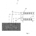
- FIG 1 shows schematically the structure of a capacitive sensor 17 for use in a DI protective switching device according to the invention according to an embodiment of the invention.
- the sensor 17 is essentially formed by the housing 29 of the DI protective switching device, the housing 29 having an electrical conductor 30 on its inside 31.
- the electrical conductor 30 can, for example, be a metallic coating on the inside 31 of the housing 29.
- the electrical conductor 30 can be connected to the evaluation electronics 14a of the detection device 14 in order to be switched according to the invention against the phase conductor or the neutral conductor for the purpose of determining the phase position (see Figure 2 ).
- the housing 29 has a surface 28 which can be enclosed by a user by hand. It represents a first electrode of the capacitor formed with the conductor 31.
- the housing material of the thickness d forms the dielectric of the capacitor and has a permittivity ⁇ .
- the permittivity describes the dielectric conductivity of the housing material.
- the area of the electrical conductor 30 on the inside 31 of the housing 29 represents the maximum available sensor area, the effectively realized capacitive area A being precisely defined by the overlap of the housing surface 28 enclosed by the hand of a user and the sensor area A.
- the thickness d of the housing 29 thus still forms the distance between the capacitor plates.
- the effective capacitance and thus the sensor capacitance can be calculated from the above values using the equation for the plate capacitor equation 1. This can be done approximately as described below.
- the sensor signal becomes worse by a factor of 234.33 when using a glove (regardless of the material constants). If the sensor surface is increased to the size of the palm of the hand, the signal with the glove only deteriorates by a factor of 7.22 in comparison to the thumb sensors known from the prior art with a correspondingly small sensor surface. Accordingly, the glove can be partially compensated for by the sensor surface. For complete compensation, the area in the present case would have to be increased to 93.33 x 10 -3 m 2 . However, this parameter is limited by the user's palm size, since only the overlap of the palm and sensor area is considered the effective area.
- the housing surface 28 should continue as possible lie flat on the hands of the user, so that an ergonomic design of the housing surface 28 is preferred.
- FIG. 2 shows a block diagram of a preferred embodiment of the DI protection switching device according to the invention.
- the L-phase conductor 1 is connected via a line 4 to a protective impedance 5 and the neutral conductor 2 via a line 6 to a protective impedance 7.
- the protective impedances 5, 7 are interconnected on the output side via conductors 8, 9 at a node 10.
- the node 10 is connected via a line 11 to a further protective impedance 12, which is connected on the output side via a conductor 13 to a device 14 for detecting the protective conductor state.
- the protective impedances 5, 7 and 12 serve to limit the current.
- the device 14 is also connected via a line 15 to the protective conductor 3 and via a line 16 to a sensor 17.
- the sensor 17 is a capacitive sensor, for example a sensor as it is with reference to FIG Figure 1 has been described.
- the output of the device 14 is connected via a conductor 18 to a switching stage 19 which switches a DI residual current circuit breaker 21 via a line 20.
- the DI residual current circuit breaker 21 is connected to a summation current transformer 22, the primary winding of which is formed by the phase conductor 1 and the neutral conductor 2.
- the summation current transformer 22 also has a secondary winding, which leads induced voltages via lines 23, 24 to evaluation electronics contained in the DI switch 21.
- the DI switch 21 is mechanically coupled to switch contacts 25, 26, 27, which are connected in lines 1, 2, 3.
- the device 14 does not recognize this fault state because of the the current flowing to the conductor 15 to the protective conductor 3 and switches the DI protective switch 21, which opens the switch contacts 25, 26, 27 and thus interrupts the conductors 1, 2, 3, via a potential-separated switching stage 19.
- the device 14 is also designed to detect the presence of an external voltage or mains voltage on the protective conductor 3.
- the capacitive sensor 17 is used which, when touched by a user, forms an electrical capacitor with a capacitive reactance with respect to the earth potential.
- the detection device 14 has evaluation electronics 14a, which is set up to determine the position of the phase by switching the sensor 17 against the phase conductor 1 and separately therefrom against the neutral conductor 2.
- the neutral conductor and the protective conductor next to the sensor are first switched in succession in order to assign the phase to a position on the L conductor or the N conductor .
- phase and the neutral conductor are checked against the protective conductor. After a signal evaluation, it can be assessed whether there is a potential difference between the neutral conductor and the protective conductor, and if so, whether it is below a touch voltage. A negligible touch voltage can be assumed, for example, if the potential difference is ⁇ 50V.
- the signal evaluation for assessing the potential difference between the neutral conductor and the PE can be carried out according to the following truth table: Phase ⁇ PE Neutral conductor ⁇ PE PE condition 0 0 not available or high impedance 0 1 energizing 1 0 available and tension-free 1 1 Function not available
- the protective conductor quality can then be checked, for example by determining a resistance of the protective conductor.
Claims (12)
- Coupe-circuit DI comprenant un transformateur de courant total (22) pour la détermination de courants de défaut dans un conducteur de phase (1) et un conducteur neutre (2) et comprenant un dispositif de détection (14) pour la détection d'états de défaut d'un conducteur de protection (3),
le dispositif de détection (14) étant raccordé du côté de l'entrée avec le conducteur de phase (1), le conducteur neutre (2) et le conducteur de protection (3) et du côté de la sortie avec un étage de commutation (19) pour la commande d'un commutateur de protection DI (21), le commutateur de protection DI (21) étant conçu pour commuter des contacts de commutation (25, 26, 27) dans la conducteur de phase (1), le conducteur neutre (2) et le conducteur de protection (2),
le dispositif de détection (14) détectant en tant qu'état de défaut la présence d'une tension de phase sur le conducteur de protection (3),
le dispositif de détection (14) comprenant un capteur capacitif (17), qui forme lors d'un contact par un utilisateur un condensateur électrique avec une réactance capacitive par rapport au potentiel terrestre, caractérisé en ce que le dispositif de détection (14) comprend en outre une électronique d'évaluation (14a), qui est conçue pour déterminer une position de phase par commutation du capteur (17) contre le conducteur de phase (1) et séparément de celui-ci contre le conducteur neutre (2), l'absence d'une tension de phase sur le conducteur de protection (3) étant conclue par l'électronique d'évaluation (14a) lorsqu'une absence de tension est calculée entre le conducteur neutre (2) et le conducteur de protection (3) par l'électronique d'évaluation (14a). - Coupe-circuit DI selon la revendication 1, caractérisé en ce qu'un côté extérieur (28) d'un boîtier diélectrique (29) du coupe-circuit DI forme le condensateur lors du contact par un utilisateur avec un conducteur électrique (30) du boîtier.
- Coupe-circuit DI selon la revendication 2, caractérisé en ce que le conducteur électrique (30) est reçu dans un espace intermédiaire du boîtier, est appliqué sur le côté extérieur du boîtier (28), ou est ou comprend un revêtement du côté intérieur (31) du boîtier (29).
- Coupe-circuit DI selon la revendication 2 ou 3, caractérisé en ce que le côté extérieur (28) du boîtier (29) est formé ergonomiquement en ce qu'un contact de grande surface entre la main ou le gant entourant la main d'un utilisateur est créé lorsque l'utilisateur couvre le boîtier (29) avec la main ou le gant.
- Coupe-circuit DI selon l'une quelconque des revendications 2 à 4, caractérisé en ce que le condensateur est chargé avec une tension par le biais du conducteur électrique (30).
- Coupe-circuit DI selon l'une quelconque des revendications précédentes, caractérisé en ce qu'une
capacité du condensateur est déterminée selon C = εA/d (Eqn. 1), s étant la permittivité du diélectrique, qui est la somme d'une épaisseur de boîtier, d'une épaisseur de peau humaine, d'inclusions d'air éventuelles et éventuellement d'une épaisseur de matériau de gant, et A est la surface du conducteur électrique (30) recouverte par le contact de l'utilisateur sur le côté intérieur (31). - Coupe-circuit DI selon l'une quelconque des revendications précédentes, caractérisé en ce que
l'électronique d'évaluation (14a) est conçue pour déterminer une position de phase sur le conducteur de phase (1) et le conducteur neutre (2), en ce qu'il commute séparément l'un de l'autre le conducteur de phase (1) et le conducteur neutre (2) contre le capteur (17) et examine à chaque fois la présence d'une chute de tension. - Coupe-circuit DI selon la revendication 7, caractérisé en ce que l'électronique d'évaluation (14a) est conçue pour déterminer la position de phase par le biais des chutes de tension déterminées qualitativement sur le conducteur de phase (1) et le conducteur neutre (2) conformément à la table de vérité suivante :
Capteur ↔ L(N) ↔ Capteur ↔N(L) ↔ Position de phase 0 0 non déterminable 0 1 N(L) 1 0 L (N) 1 1 non déterminable - Coupe-circuit DI selon l'une quelconque des revendications précédentes, caractérisé en ce que
le microcontrôleur est en outre conçu pour examiner une chute de tension en connaissance de la position de phase du conducteur de phase (1) contre le conducteur de protection (3) et du conducteur neutre (2) contre le conducteur de protection (3), l'électronique d'évaluation (14a) ne concluant alors à un conducteur de protection (3) correct que lorsqu'une chute de tension est présente conformément à la position de phase déterminée par rapport au conducteur de phase (1) et qu'une absence de tension est présente par rapport au conducteur neutre (2) ou une chute de tension en dessous d'une tension de contact, de préférence en dessous d'une tension de 50 V. - Coupe-circuit DI selon la revendication 9, caractérisé en ce que l'électronique d'évaluation (14a) est conçue pour déterminer un état du conducteur de protection (3) par le biais de l'examen du conducteur de phase (1) contre le conducteur de protection (3) et du conducteur neutre (2) contre le conducteur de protection (3) pour déterminer une chute de tension conformément à la table de vérité suivante :
Phase H ↔ PE Conducteur neutre H ↔ PE État PE 0 0 non présent ou de grande valeur ohmique 0 1 sous tension 1 0 présent et exempt de tension 1 1 Fonction non présente - Procédé pour l'exploitation d'un coupe-circuit DI selon l'une quelconque des revendications précédentes, comprenant les étapes suivantes :- le contact du capteur (17) du coupe-circuit DI avec une main, qui est éventuellement entourée par une protection de main, un condensateur électrique ayant une réactance capacitive par rapport au potentiel terrestre étant créé ;- séparément l'un de l'autre, la commutation du conducteur de phase (1) et du conducteur neutre (2) contre le capteur (17) et la détermination d'une position de phase ;- en connaissance de la position de phase, l'examen du conducteur de phase () contre le conducteur de protection (3) et du conducteur neutre (2) contre le conducteur de protection (3) pour déterminer une chute de tension ; et- la fermeture de contacts de commutation du conducteur de phase (1), du conducteur neutre (2) et du conducteur de protection (3) uniquement lorsque l'examen a indiqué que le conducteur de protection est présente/à faible valeur ohmique et/ou exempt de tension.
- Procédé selon la revendication 11, caractérisé en ce que
celui-ci comprend l'entourage d'un boîtier (29) du coupe-circuit DI de telle sorte qu'une surface de contact la plus grande possible entre la main ou le gant d'un utilisateur et le côté extérieur (28) du boîtier (29) soit créé.
Priority Applications (9)
| Application Number | Priority Date | Filing Date | Title |
|---|---|---|---|
| DK17160188.3T DK3373403T3 (da) | 2017-03-09 | 2017-03-09 | Differentialstrømsbeskyttelse og driftsfremgangsmåde til at detektere en spænding på PEN-lederen |
| PT171601883T PT3373403T (pt) | 2017-03-09 | 2017-03-09 | Dispositivo disjuntor di e processso operacional para identificação de uma tensão no condutor pen |
| EP17160188.3A EP3373403B1 (fr) | 2017-03-09 | 2017-03-09 | Coupe-circuit di et procédé de fonctionnement pour détecter une tension sur le conducteur pen |
| ES17160188T ES2817541T3 (es) | 2017-03-09 | 2017-03-09 | Dispositivo de conmutación de protección DI y procedimiento de funcionamiento para identificar una tensión en el conductor PEN |
| AU2018229730A AU2018229730B2 (en) | 2017-03-09 | 2018-03-06 | DI-circuit breaker device and operating method for detecting a voltage on the pen conductor |
| US16/492,540 US11228175B2 (en) | 2017-03-09 | 2018-03-06 | Di-circuit breaker device and operating method for detecting a voltage on a pen conductor |
| CN201880017298.3A CN110612649B (zh) | 2017-03-09 | 2018-03-06 | 用于识别pen导体上的电压的di断路器装置和操作方法 |
| JP2019570618A JP7035095B2 (ja) | 2017-03-09 | 2018-03-06 | Pen導体上の電圧を識別するためのdi回路遮断装置およびその動作方法 |
| PCT/EP2018/055417 WO2018162452A1 (fr) | 2017-03-09 | 2018-03-06 | Ensemble disjoncteur à courant différentiel résiduel (di) et procédé de fonctionnement pour détecter une tension sur le conducteur pen |
Applications Claiming Priority (1)
| Application Number | Priority Date | Filing Date | Title |
|---|---|---|---|
| EP17160188.3A EP3373403B1 (fr) | 2017-03-09 | 2017-03-09 | Coupe-circuit di et procédé de fonctionnement pour détecter une tension sur le conducteur pen |
Publications (2)
| Publication Number | Publication Date |
|---|---|
| EP3373403A1 EP3373403A1 (fr) | 2018-09-12 |
| EP3373403B1 true EP3373403B1 (fr) | 2020-06-10 |
Family
ID=58314115
Family Applications (1)
| Application Number | Title | Priority Date | Filing Date |
|---|---|---|---|
| EP17160188.3A Active EP3373403B1 (fr) | 2017-03-09 | 2017-03-09 | Coupe-circuit di et procédé de fonctionnement pour détecter une tension sur le conducteur pen |
Country Status (9)
| Country | Link |
|---|---|
| US (1) | US11228175B2 (fr) |
| EP (1) | EP3373403B1 (fr) |
| JP (1) | JP7035095B2 (fr) |
| CN (1) | CN110612649B (fr) |
| AU (1) | AU2018229730B2 (fr) |
| DK (1) | DK3373403T3 (fr) |
| ES (1) | ES2817541T3 (fr) |
| PT (1) | PT3373403T (fr) |
| WO (1) | WO2018162452A1 (fr) |
Families Citing this family (4)
| Publication number | Priority date | Publication date | Assignee | Title |
|---|---|---|---|---|
| JP6410915B1 (ja) * | 2017-12-19 | 2018-10-24 | 馬鞍山市明珠電子科技有限公司 | 電気機器及び電気機器の接地状態検知方法 |
| GB2578339B (en) * | 2019-03-25 | 2020-12-30 | Greentec International Ltd | Open PEN detection and shut down system |
| DE102021133662A1 (de) | 2021-12-14 | 2023-06-15 | Doepke Schaltgeräte GmbH | Verfahren zur Erkennung von Fehlerzuständen eines Schutzleiters |
| GB202209385D0 (en) * | 2022-06-27 | 2022-08-10 | Shell Int Research | Electrical protection system |
Family Cites Families (10)
| Publication number | Priority date | Publication date | Assignee | Title |
|---|---|---|---|---|
| JPS5414441B2 (fr) * | 1974-10-08 | 1979-06-07 | ||
| DE19618279A1 (de) | 1996-05-07 | 1997-11-13 | Kopp Heinrich Ag | DI-Schutzschalteinrichtung |
| JP2011229270A (ja) * | 2010-04-19 | 2011-11-10 | Oki Electric Ind Co Ltd | 電源ユニット |
| DE102010050767B3 (de) * | 2010-11-10 | 2012-02-02 | Norbert Bauriedel | Stecker mit Verpolungsschutz |
| DE202012012590U1 (de) * | 2012-01-13 | 2013-08-07 | Siemens Aktiengesellschaft | Vorrichtungen zum Überwachen eines Schutzleiters |
| DE102013205236A1 (de) * | 2012-10-17 | 2014-04-17 | Siemens Aktiengesellschaft | Überwachungsvorrichtung und Verfahren zum Überwachen einer Restspannung |
| US9607786B2 (en) * | 2012-11-20 | 2017-03-28 | Pass & Seymour, Inc. | Electronic switching device and system |
| DE102013212739B3 (de) * | 2013-06-28 | 2014-12-04 | Siemens Aktiengesellschaft | Stecker mit einem Schutzleiterkontakt |
| EP3057235B1 (fr) * | 2015-02-10 | 2020-07-08 | Nxp B.V. | Capteur tactile |
| DE102016105882A1 (de) * | 2016-03-31 | 2017-10-05 | As - Schwabe Gmbh | Verfahren und Vorrichtung zur Schutzleiterüberwachung |
-
2017
- 2017-03-09 DK DK17160188.3T patent/DK3373403T3/da active
- 2017-03-09 PT PT171601883T patent/PT3373403T/pt unknown
- 2017-03-09 EP EP17160188.3A patent/EP3373403B1/fr active Active
- 2017-03-09 ES ES17160188T patent/ES2817541T3/es active Active
-
2018
- 2018-03-06 JP JP2019570618A patent/JP7035095B2/ja active Active
- 2018-03-06 US US16/492,540 patent/US11228175B2/en active Active
- 2018-03-06 WO PCT/EP2018/055417 patent/WO2018162452A1/fr active Application Filing
- 2018-03-06 AU AU2018229730A patent/AU2018229730B2/en active Active
- 2018-03-06 CN CN201880017298.3A patent/CN110612649B/zh active Active
Non-Patent Citations (1)
| Title |
|---|
| None * |
Also Published As
| Publication number | Publication date |
|---|---|
| DK3373403T3 (da) | 2020-09-14 |
| AU2018229730B2 (en) | 2022-08-11 |
| US11228175B2 (en) | 2022-01-18 |
| PT3373403T (pt) | 2020-09-03 |
| JP2020511928A (ja) | 2020-04-16 |
| US20210143635A1 (en) | 2021-05-13 |
| JP7035095B2 (ja) | 2022-03-14 |
| ES2817541T3 (es) | 2021-04-07 |
| AU2018229730A1 (en) | 2019-09-26 |
| WO2018162452A1 (fr) | 2018-09-13 |
| CN110612649B (zh) | 2022-10-25 |
| CN110612649A (zh) | 2019-12-24 |
| EP3373403A1 (fr) | 2018-09-12 |
Similar Documents
| Publication | Publication Date | Title |
|---|---|---|
| EP3373403B1 (fr) | Coupe-circuit di et procédé de fonctionnement pour détecter une tension sur le conducteur pen | |
| DE102011005551B4 (de) | Belegungserkennungsvorrichtung zum Erkennen einer Belegung eines Sitzplatzes eines Kraftfahrzeuges | |
| EP3216127A2 (fr) | Dispositif et procédé de détection d'un contact avec le volant | |
| DE112013006074T5 (de) | Kapazitiver Sensor, der dafür ausgelegt ist, ein Heizelement als Antennenelektrode zu verwenden | |
| EP1857825A1 (fr) | Dispositif de mesure | |
| EP1094750A1 (fr) | Procede pour reconnaitre l'etat vivant de la peau humaine | |
| EP1066178B1 (fr) | Procede de detection capacitive d'objets dans les vehicules | |
| DE102014117823A1 (de) | Lenkrad für ein Kraftfahrzeug mit einem Sensorsystem und Verfahren zum Erkennen einer Anwesenheit einer menschlichen Hand in einem Greifbereich eines solchen Lenkrads | |
| DE112013005610T5 (de) | Kapazitiver Belegungs- oder Näherungsdetektor | |
| DE102019120136A1 (de) | Kapazitive Sensorvorrichtung, Lenkrad mit einer kapazitiven Sensorvorrichtung, Verfahren zum Betrieb einer kapazitiven Sensorvorrichtung und/oder eines Lenkrads sowie Fahrzeug mit einer kapazitiven Sensorvorrichtung | |
| WO2016087231A1 (fr) | Système de détection pour un volant de véhicule à moteur, volant doté d'un tel système de détection et procédé pour faire fonctionner un tel système de détection | |
| DE112016001348T5 (de) | Kapazitives Erfassungssystem mit Gerätediagnosekonzept zur Erfassung einer Sensorunterbrechung | |
| DE102011078369B4 (de) | Kapazitive Sensoreinrichtung sowie Verfahren zum Kalibrieren einer kapazitiven Sensoreinrichtung | |
| EP2700427B1 (fr) | Dispositif de chauffage de fluide et procédé de fonctionnement d'un dispositif de chauffage de fluide | |
| EP3016225B1 (fr) | Dispositif de reconnaissance et procédé de reconnaissance d'états défectueux d'un conducteur de mise à la terre | |
| EP3788388B1 (fr) | Dispositif capteur et procédé de détermination d'une tension alternative | |
| EP3637948B1 (fr) | Dispositif de chauffage et procédé d'enregistrement de température sur un dispositif de chauffage | |
| DE112019005884T5 (de) | Sensoranordnung zur kapazitiven Positionserfassung einer Hand an einem Lenkrad | |
| DE102009032357B3 (de) | Detektionseinrichtung für ein elektrisches Handgerät sowie Handgerät mit einer Detektionseinrichtung | |
| EP2974023B1 (fr) | Ensemble de détection capacitive équipé d'une électrode de protection | |
| EP0993993A1 (fr) | Procédé de reconnaisance capacitive d'object pour vehicules | |
| DE102015204207A1 (de) | Herstellen eines elektrischen Kontakts mit Haut | |
| DE102013021823A1 (de) | Vorrichtung zum Erfassen einer elektrodermalen Aktivität einer Person, Lenkrad, Kraftfahrzeug und entsprechendes Verfahren | |
| DE102009050279B4 (de) | Vorrichtung und Verfahren zur Überprüfung des Widerstandes elektrischer Erdungsverbindungen | |
| EP2862531B1 (fr) | Dispositif de test d'instruments |
Legal Events
| Date | Code | Title | Description |
|---|---|---|---|
| PUAI | Public reference made under article 153(3) epc to a published international application that has entered the european phase |
Free format text: ORIGINAL CODE: 0009012 |
|
| STAA | Information on the status of an ep patent application or granted ep patent |
Free format text: STATUS: THE APPLICATION HAS BEEN PUBLISHED |
|
| AK | Designated contracting states |
Kind code of ref document: A1 Designated state(s): AL AT BE BG CH CY CZ DE DK EE ES FI FR GB GR HR HU IE IS IT LI LT LU LV MC MK MT NL NO PL PT RO RS SE SI SK SM TR |
|
| AX | Request for extension of the european patent |
Extension state: BA ME |
|
| STAA | Information on the status of an ep patent application or granted ep patent |
Free format text: STATUS: REQUEST FOR EXAMINATION WAS MADE |
|
| 17P | Request for examination filed |
Effective date: 20190307 |
|
| RBV | Designated contracting states (corrected) |
Designated state(s): AL AT BE BG CH CY CZ DE DK EE ES FI FR GB GR HR HU IE IS IT LI LT LU LV MC MK MT NL NO PL PT RO RS SE SI SK SM TR |
|
| REG | Reference to a national code |
Ref country code: DE Ref legal event code: R079 Ref document number: 502017005616 Country of ref document: DE Free format text: PREVIOUS MAIN CLASS: H02H0003140000 Ipc: G01R0015160000 |
|
| RIC1 | Information provided on ipc code assigned before grant |
Ipc: H02H 11/00 20060101ALI20191106BHEP Ipc: G01R 19/155 20060101ALI20191106BHEP Ipc: G01R 15/16 20060101AFI20191106BHEP Ipc: H02H 5/10 20060101ALI20191106BHEP Ipc: H02H 1/00 20060101ALI20191106BHEP Ipc: H02H 3/33 20060101ALI20191106BHEP Ipc: H02H 5/00 20060101ALI20191106BHEP Ipc: H02H 3/14 20060101ALI20191106BHEP Ipc: G01R 31/02 20060101ALI20191106BHEP |
|
| GRAP | Despatch of communication of intention to grant a patent |
Free format text: ORIGINAL CODE: EPIDOSNIGR1 |
|
| STAA | Information on the status of an ep patent application or granted ep patent |
Free format text: STATUS: GRANT OF PATENT IS INTENDED |
|
| INTG | Intention to grant announced |
Effective date: 20200108 |
|
| GRAS | Grant fee paid |
Free format text: ORIGINAL CODE: EPIDOSNIGR3 |
|
| GRAA | (expected) grant |
Free format text: ORIGINAL CODE: 0009210 |
|
| STAA | Information on the status of an ep patent application or granted ep patent |
Free format text: STATUS: THE PATENT HAS BEEN GRANTED |
|
| AK | Designated contracting states |
Kind code of ref document: B1 Designated state(s): AL AT BE BG CH CY CZ DE DK EE ES FI FR GB GR HR HU IE IS IT LI LT LU LV MC MK MT NL NO PL PT RO RS SE SI SK SM TR |
|
| REG | Reference to a national code |
Ref country code: GB Ref legal event code: FG4D Free format text: NOT ENGLISH |
|
| REG | Reference to a national code |
Ref country code: CH Ref legal event code: EP Ref country code: AT Ref legal event code: REF Ref document number: 1279606 Country of ref document: AT Kind code of ref document: T Effective date: 20200615 |
|
| REG | Reference to a national code |
Ref country code: DE Ref legal event code: R096 Ref document number: 502017005616 Country of ref document: DE |
|
| REG | Reference to a national code |
Ref country code: IE Ref legal event code: FG4D Free format text: LANGUAGE OF EP DOCUMENT: GERMAN |
|
| REG | Reference to a national code |
Ref country code: PT Ref legal event code: SC4A Ref document number: 3373403 Country of ref document: PT Date of ref document: 20200903 Kind code of ref document: T Free format text: AVAILABILITY OF NATIONAL TRANSLATION Effective date: 20200827 |
|
| REG | Reference to a national code |
Ref country code: FI Ref legal event code: FGE |
|
| REG | Reference to a national code |
Ref country code: DK Ref legal event code: T3 Effective date: 20200909 |
|
| REG | Reference to a national code |
Ref country code: CH Ref legal event code: NV Representative=s name: PATENTANWAELTE SCHAAD, BALASS, MENZL AND PARTN, CH |
|
| REG | Reference to a national code |
Ref country code: NL Ref legal event code: FP |
|
| REG | Reference to a national code |
Ref country code: SE Ref legal event code: TRGR |
|
| REG | Reference to a national code |
Ref country code: LT Ref legal event code: MG4D |
|
| PG25 | Lapsed in a contracting state [announced via postgrant information from national office to epo] |
Ref country code: LT Free format text: LAPSE BECAUSE OF FAILURE TO SUBMIT A TRANSLATION OF THE DESCRIPTION OR TO PAY THE FEE WITHIN THE PRESCRIBED TIME-LIMIT Effective date: 20200610 Ref country code: GR Free format text: LAPSE BECAUSE OF FAILURE TO SUBMIT A TRANSLATION OF THE DESCRIPTION OR TO PAY THE FEE WITHIN THE PRESCRIBED TIME-LIMIT Effective date: 20200911 |
|
| REG | Reference to a national code |
Ref country code: NO Ref legal event code: T2 Effective date: 20200610 |
|
| PG25 | Lapsed in a contracting state [announced via postgrant information from national office to epo] |
Ref country code: LV Free format text: LAPSE BECAUSE OF FAILURE TO SUBMIT A TRANSLATION OF THE DESCRIPTION OR TO PAY THE FEE WITHIN THE PRESCRIBED TIME-LIMIT Effective date: 20200610 Ref country code: HR Free format text: LAPSE BECAUSE OF FAILURE TO SUBMIT A TRANSLATION OF THE DESCRIPTION OR TO PAY THE FEE WITHIN THE PRESCRIBED TIME-LIMIT Effective date: 20200610 Ref country code: BG Free format text: LAPSE BECAUSE OF FAILURE TO SUBMIT A TRANSLATION OF THE DESCRIPTION OR TO PAY THE FEE WITHIN THE PRESCRIBED TIME-LIMIT Effective date: 20200910 Ref country code: RS Free format text: LAPSE BECAUSE OF FAILURE TO SUBMIT A TRANSLATION OF THE DESCRIPTION OR TO PAY THE FEE WITHIN THE PRESCRIBED TIME-LIMIT Effective date: 20200610 |
|
| PG25 | Lapsed in a contracting state [announced via postgrant information from national office to epo] |
Ref country code: AL Free format text: LAPSE BECAUSE OF FAILURE TO SUBMIT A TRANSLATION OF THE DESCRIPTION OR TO PAY THE FEE WITHIN THE PRESCRIBED TIME-LIMIT Effective date: 20200610 |
|
| PG25 | Lapsed in a contracting state [announced via postgrant information from national office to epo] |
Ref country code: RO Free format text: LAPSE BECAUSE OF FAILURE TO SUBMIT A TRANSLATION OF THE DESCRIPTION OR TO PAY THE FEE WITHIN THE PRESCRIBED TIME-LIMIT Effective date: 20200610 Ref country code: EE Free format text: LAPSE BECAUSE OF FAILURE TO SUBMIT A TRANSLATION OF THE DESCRIPTION OR TO PAY THE FEE WITHIN THE PRESCRIBED TIME-LIMIT Effective date: 20200610 Ref country code: CZ Free format text: LAPSE BECAUSE OF FAILURE TO SUBMIT A TRANSLATION OF THE DESCRIPTION OR TO PAY THE FEE WITHIN THE PRESCRIBED TIME-LIMIT Effective date: 20200610 Ref country code: SM Free format text: LAPSE BECAUSE OF FAILURE TO SUBMIT A TRANSLATION OF THE DESCRIPTION OR TO PAY THE FEE WITHIN THE PRESCRIBED TIME-LIMIT Effective date: 20200610 |
|
| PG25 | Lapsed in a contracting state [announced via postgrant information from national office to epo] |
Ref country code: PL Free format text: LAPSE BECAUSE OF FAILURE TO SUBMIT A TRANSLATION OF THE DESCRIPTION OR TO PAY THE FEE WITHIN THE PRESCRIBED TIME-LIMIT Effective date: 20200610 Ref country code: SK Free format text: LAPSE BECAUSE OF FAILURE TO SUBMIT A TRANSLATION OF THE DESCRIPTION OR TO PAY THE FEE WITHIN THE PRESCRIBED TIME-LIMIT Effective date: 20200610 Ref country code: IS Free format text: LAPSE BECAUSE OF FAILURE TO SUBMIT A TRANSLATION OF THE DESCRIPTION OR TO PAY THE FEE WITHIN THE PRESCRIBED TIME-LIMIT Effective date: 20201010 |
|
| REG | Reference to a national code |
Ref country code: DE Ref legal event code: R097 Ref document number: 502017005616 Country of ref document: DE |
|
| REG | Reference to a national code |
Ref country code: ES Ref legal event code: FG2A Ref document number: 2817541 Country of ref document: ES Kind code of ref document: T3 Effective date: 20210407 |
|
| PLBE | No opposition filed within time limit |
Free format text: ORIGINAL CODE: 0009261 |
|
| STAA | Information on the status of an ep patent application or granted ep patent |
Free format text: STATUS: NO OPPOSITION FILED WITHIN TIME LIMIT |
|
| 26N | No opposition filed |
Effective date: 20210311 |
|
| PG25 | Lapsed in a contracting state [announced via postgrant information from national office to epo] |
Ref country code: SI Free format text: LAPSE BECAUSE OF FAILURE TO SUBMIT A TRANSLATION OF THE DESCRIPTION OR TO PAY THE FEE WITHIN THE PRESCRIBED TIME-LIMIT Effective date: 20200610 |
|
| REG | Reference to a national code |
Ref country code: FI Ref legal event code: MAE |
|
| PG25 | Lapsed in a contracting state [announced via postgrant information from national office to epo] |
Ref country code: FI Free format text: LAPSE BECAUSE OF NON-PAYMENT OF DUE FEES Effective date: 20210309 Ref country code: MC Free format text: LAPSE BECAUSE OF FAILURE TO SUBMIT A TRANSLATION OF THE DESCRIPTION OR TO PAY THE FEE WITHIN THE PRESCRIBED TIME-LIMIT Effective date: 20200610 |
|
| REG | Reference to a national code |
Ref country code: DK Ref legal event code: EBP Effective date: 20210331 |
|
| GBPC | Gb: european patent ceased through non-payment of renewal fee |
Effective date: 20210309 |
|
| REG | Reference to a national code |
Ref country code: BE Ref legal event code: MM Effective date: 20210331 |
|
| PG25 | Lapsed in a contracting state [announced via postgrant information from national office to epo] |
Ref country code: PT Free format text: LAPSE BECAUSE OF NON-PAYMENT OF DUE FEES Effective date: 20211209 Ref country code: GB Free format text: LAPSE BECAUSE OF NON-PAYMENT OF DUE FEES Effective date: 20210309 Ref country code: IE Free format text: LAPSE BECAUSE OF NON-PAYMENT OF DUE FEES Effective date: 20210309 Ref country code: LU Free format text: LAPSE BECAUSE OF NON-PAYMENT OF DUE FEES Effective date: 20210309 |
|
| PG25 | Lapsed in a contracting state [announced via postgrant information from national office to epo] |
Ref country code: DK Free format text: LAPSE BECAUSE OF NON-PAYMENT OF DUE FEES Effective date: 20210331 |
|
| REG | Reference to a national code |
Ref country code: ES Ref legal event code: FD2A Effective date: 20220523 |
|
| PG25 | Lapsed in a contracting state [announced via postgrant information from national office to epo] |
Ref country code: ES Free format text: LAPSE BECAUSE OF NON-PAYMENT OF DUE FEES Effective date: 20210310 Ref country code: BE Free format text: LAPSE BECAUSE OF NON-PAYMENT OF DUE FEES Effective date: 20210331 |
|
| PG25 | Lapsed in a contracting state [announced via postgrant information from national office to epo] |
Ref country code: IT Free format text: LAPSE BECAUSE OF NON-PAYMENT OF DUE FEES Effective date: 20210309 |
|
| PGFP | Annual fee paid to national office [announced via postgrant information from national office to epo] |
Ref country code: NO Payment date: 20230309 Year of fee payment: 7 Ref country code: FR Payment date: 20230123 Year of fee payment: 7 Ref country code: AT Payment date: 20230227 Year of fee payment: 7 |
|
| PGFP | Annual fee paid to national office [announced via postgrant information from national office to epo] |
Ref country code: SE Payment date: 20230126 Year of fee payment: 7 |
|
| P01 | Opt-out of the competence of the unified patent court (upc) registered |
Effective date: 20230403 |
|
| PG25 | Lapsed in a contracting state [announced via postgrant information from national office to epo] |
Ref country code: CY Free format text: LAPSE BECAUSE OF FAILURE TO SUBMIT A TRANSLATION OF THE DESCRIPTION OR TO PAY THE FEE WITHIN THE PRESCRIBED TIME-LIMIT Effective date: 20200610 |
|
| PGFP | Annual fee paid to national office [announced via postgrant information from national office to epo] |
Ref country code: NL Payment date: 20230125 Year of fee payment: 7 |
|
| PG25 | Lapsed in a contracting state [announced via postgrant information from national office to epo] |
Ref country code: HU Free format text: LAPSE BECAUSE OF FAILURE TO SUBMIT A TRANSLATION OF THE DESCRIPTION OR TO PAY THE FEE WITHIN THE PRESCRIBED TIME-LIMIT; INVALID AB INITIO Effective date: 20170309 |
|
| PGFP | Annual fee paid to national office [announced via postgrant information from national office to epo] |
Ref country code: DE Payment date: 20230331 Year of fee payment: 7 Ref country code: CH Payment date: 20230401 Year of fee payment: 7 |
|
| PGFP | Annual fee paid to national office [announced via postgrant information from national office to epo] |
Ref country code: NL Payment date: 20240315 Year of fee payment: 8 |
|
| PGFP | Annual fee paid to national office [announced via postgrant information from national office to epo] |
Ref country code: AT Payment date: 20240226 Year of fee payment: 8 |