EP1857825A1 - Dispositif de mesure - Google Patents
Dispositif de mesure Download PDFInfo
- Publication number
- EP1857825A1 EP1857825A1 EP07008171A EP07008171A EP1857825A1 EP 1857825 A1 EP1857825 A1 EP 1857825A1 EP 07008171 A EP07008171 A EP 07008171A EP 07008171 A EP07008171 A EP 07008171A EP 1857825 A1 EP1857825 A1 EP 1857825A1
- Authority
- EP
- European Patent Office
- Prior art keywords
- switch
- current
- insulation resistance
- iso
- arrangement according
- Prior art date
- Legal status (The legal status is an assumption and is not a legal conclusion. Google has not performed a legal analysis and makes no representation as to the accuracy of the status listed.)
- Granted
Links
Images


Classifications
-
- G—PHYSICS
- G01—MEASURING; TESTING
- G01R—MEASURING ELECTRIC VARIABLES; MEASURING MAGNETIC VARIABLES
- G01R27/00—Arrangements for measuring resistance, reactance, impedance, or electric characteristics derived therefrom
- G01R27/02—Measuring real or complex resistance, reactance, impedance, or other two-pole characteristics derived therefrom, e.g. time constant
- G01R27/16—Measuring impedance of element or network through which a current is passing from another source, e.g. cable, power line
- G01R27/18—Measuring resistance to earth, i.e. line to ground
-
- Y—GENERAL TAGGING OF NEW TECHNOLOGICAL DEVELOPMENTS; GENERAL TAGGING OF CROSS-SECTIONAL TECHNOLOGIES SPANNING OVER SEVERAL SECTIONS OF THE IPC; TECHNICAL SUBJECTS COVERED BY FORMER USPC CROSS-REFERENCE ART COLLECTIONS [XRACs] AND DIGESTS
- Y02—TECHNOLOGIES OR APPLICATIONS FOR MITIGATION OR ADAPTATION AGAINST CLIMATE CHANGE
- Y02E—REDUCTION OF GREENHOUSE GAS [GHG] EMISSIONS, RELATED TO ENERGY GENERATION, TRANSMISSION OR DISTRIBUTION
- Y02E10/00—Energy generation through renewable energy sources
- Y02E10/50—Photovoltaic [PV] energy
Definitions
- the invention relates to a measuring arrangement with a grounding point for determining the insulation resistance (R iso ) of an electrical device under voltage or a system with a supply voltage (U B ) having a positive pole and a negative pole, wherein two switches (S 1 and S 2 ) or a corresponding switch are present, each of which establish a current path between one of the two poles and the grounding point to determine the occurrence of one or more insulation fault with any potential reference the total resulting insulation resistance (R iso ).
- moisture, contamination, short circuits or other causes may cause insulation faults between a live part of the system and ground.
- R iso always corresponds to the parallel connection of all leakage resistances, while U x or the ratio R n / R p gives an indication of the position of the ground faults.
- isolation errors R p and R n occur at the same time, the method described no longer functions, since only one value R n or R p can be determined in each case.
- a ground fault which arises at a potential other than positive or negative pole, can not be described with an equivalent circuit diagram of only one resistor.
- a low-resistance insulation fault can be better evaluated if, for example, in the case of an insulation fault from positive to earth, the known, high-impedance resistor is switched to the negative pole and vice versa.
- the additional measurement with a closed switch will only be carried out if limit values are already exceeded in the measurement with opened switches.
- Ground faults that do not occur directly at the positive or negative pole, but potentials in between, are not necessarily found with this method. For example, a ground fault in the middle of a photovoltaic generator would not lead to a change in the measured voltage when the switches are open, so that no measurement would be carried out with the switch closed and therefore the ground fault could not be detected.
- the measurement process is generally defined so that one measurement cycle comprises one measurement with two switches open and one measurement with one open and one closed switch.
- the script does not specify which of the two switches should be closed; this decision is made more meaningful, however, as in the DE 35 13 849 met. If one prefers ideal measuring equipment, one could exactly determine any earth faults with this method.
- R L ⁇ 1 R s ⁇ v 1 v 2 ⁇ v 2 ⁇ ' v 1 ⁇ ' - 1
- R L ⁇ 2 R s ⁇ v 2 ⁇ ' v 1 ⁇ ' - v 2 v 1 used.
- the disadvantage is that in order to calculate the leakage resistances R n (R L1 ) and R p (R L2 ) it is necessary to measure two instantaneous values of two different voltages and to know the exact value of the connected resistor. Since all measured variables are subject to a measurement error in practice, the measurement errors of both voltages are included in the calculated resistance values.
- This arrangement is used, for example, in a DC system for the London Underground.
- the invention has for its object to provide a measuring device with which an accurate measurement of the insulation resistance R iso is possible, even if in each case leakage resistance to plus and minus, R p and R n occur simultaneously or a leakage resistance occurs at an intermediate potential. In order to minimize the influence of possible measurement errors, as few as possible measured variables should be used to calculate R iso .
- the measuring procedure is opposite to the procedure EP 0 833 423 modified so that a measurement cycle includes both a measurement with open switch S 1 and closed switch S 2 as well as a measurement with open switch S 2 and closed switch S 1 .
- the other structure can be left unchanged, in particular two high-resistance resistors R S are used with known, equal value in series with the two switches.
- R n R s ⁇ U 1 ⁇ ' U 1 - 1 be determined.
- the unprimed variables U 1 , U 2 represent measured values with the switch S 1 closed and the switch S 2 open, while the canceled variables U1 ', U2' represent the measured values when the switch S 1 is open and the switch S 2 is closed.
- An important advantage of the invention is that a measurement with high accuracy is possible even if multiple leakage resistances are present.
- the measuring arrangement thus works perfectly even if leakage resistances R n and R p occur simultaneously or an insulation fault occurs at a location which is not on the positive or the negative pole, for example in the middle of a solar generator.
- the insulation resistances determined would be higher than actually, so that the user would erroneously weigh in safety. Even with the improved arrangements after EP 1 265 076 .
- a second embodiment of the invention according to claim 3 one can replace the two voltage measuring devices by a single current measuring device between the connection point of the two switches and earth (Fig. 4).
- the two resistors R S are then no longer needed for the measurement, so that their tolerances no longer go into the measurement accuracy.
- the measurement is such that a PE conductor (earth) via a switching element, For example, a relay is connected in succession to the plus and the minus of the supply voltage, now each of the currents are measured in the switched connections.
- An offset error of the current measurement has no influence on the determined R iso value by the difference measurement, so that the measurement accuracy is again improved.
- the complex potential-free current measurement is relocated to one of the two poles of the system, so that the evaluation can be made easier by a microprocessor with a corresponding reference potential (Fig. 5).
- a switch S 2 is not directly connected to a pole, but via a current source that requires a negligible in relation to the operating voltage U B supply voltage.
- a correspondingly controlled transistor for example a bipolar transistor with the highest possible current gain or a field effect transistor.
- the collector or drain terminal of the transistor is connected to the not connected to PE terminal of the second switch S 1 . Between this connection point and the second pole is a current measuring device connected.
- the current I plus can be passed through a shunt which is connected to an A / D converter in the microcontroller. The microcontroller can then take successively the readings for U B , L plus and L plus and calculate R iso .
- the measurement of the insulation resistance in photovoltaic systems for the generation of electrical energy is particularly advantageous. Precise monitoring of ground faults can detect in good time a hazard to persons or sensitive electronic devices, even if several insulation faults occur at different potentials.
- the use of the measuring arrangement according to the invention in transformerless inverters is particularly advantageous.
- low-resistance ground faults are also a danger in the generator center, as this practically short circuits the inverter output.
- the resulting high currents can lead to damage or destruction of the power semiconductors. Damage to the semiconductors of the inverter
- other safety measures such as current monitoring can be avoided, the cause of the fault would not be displayed.
- the search for the error would be tedious and costly if no measurement of the insulation resistance takes place.
- the insulation resistance measurement according to the invention can timely indicate the error and prevent the connection of the inverter to the public grid.
- transformerless inverters can be reliably protected and downtimes effectively shortened by the invention.
- FIG. 1 shows a grid-connected photovoltaic system as an example of a system to be monitored for insulation faults.
- Components of the system are a photovoltaic generator 1 of a plurality of solar cells 2 and an inverter 3, which is connected to an AC voltage network 4, which is connected to the earth 5.
- the system has a positive pole 6 and a negative pole 7.
- the inverter 3 consists for example of a buffer capacitor 8, power semiconductors 9, storage chokes 10 and a device for mains connection 11.
- a leakage resistance R p 12 between positive pole 6 and earth 5 a leakage resistance R n 13 between minus 7 and ground 5 and a leakage resistance R x 14 from any potential to earth 5 located .
- R iso 1 1 R p + 1 R n + 1 R x
- a single insulation fault at the positive or negative pole ie a single leakage resistance R p or R n
- R p or R n can be determined with a simple arrangement according to FIG. 2.
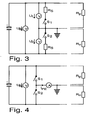
- Fig. 3 shows a first embodiment of the invention.
- the construction shown is also in the EP 0 833 423 used.
- a measurement cycle is defined so that a first measurement with closed switch S 1 and open switch S 2 and then a second measurement with closed switch S 2 and opened switch S 1 is performed. This results, as already stated, simple equations with little error.
- Fig. 4 shows a second embodiment of the invention.
- a current measuring device between ground 5 and the connection point of the two switches is provided to measure the current for calculating the insulation resistance.
- the measuring cycle remains unchanged from the rule for FIG. 3.
- Fig. 5 shows a preferred third embodiment of the invention.
- the circuit uses an additional constant current source, which supplies the constant current I const .
- the switch S 2 is not switched directly to the positive pole, but via the power source.
- a MOSFET with suitable control U G is connected in parallel to the two switches S 1 and S 2 .
- the advantage here is that instead of the current I PE with respect to the earth 5, a current I plus is measured with respect to the positive pole of the system. The current can thus be measured, for example via a shunt, well with a microprocessor whose reference potential lies on this pole. As with the embodiment according to FIG. 4, an accurate measurement without high-precision resistances is possible with this solution.
- the insulation resistance R iso of a live electrical device or a system with a plus pole 6 and a minus pole 7 can thus be determined with the presented method and the described measuring arrangements.
- Both switches S 1 , S 2 each make a current path between ground and one of the two poles 6,7 when closing. With this arrangement, insulation errors at both poles 6,7, on any potentials in between and any combinations of these error cases are detected. The total resulting insulation resistance can be determined very accurately in a simple manner.
Applications Claiming Priority (1)
| Application Number | Priority Date | Filing Date | Title |
|---|---|---|---|
| DE102006022686.0A DE102006022686B4 (de) | 2006-05-16 | 2006-05-16 | Messanordnung zur Ermittlung des Isolationswiderstandes einer elektrischen Vorrichtung oder einer Anlage |
Publications (2)
| Publication Number | Publication Date |
|---|---|
| EP1857825A1 true EP1857825A1 (fr) | 2007-11-21 |
| EP1857825B1 EP1857825B1 (fr) | 2019-07-10 |
Family
ID=38371028
Family Applications (1)
| Application Number | Title | Priority Date | Filing Date |
|---|---|---|---|
| EP07008171.6A Active EP1857825B1 (fr) | 2006-05-16 | 2007-04-21 | Dispositif de mesure |
Country Status (3)
| Country | Link |
|---|---|
| US (2) | US7576547B2 (fr) |
| EP (1) | EP1857825B1 (fr) |
| DE (1) | DE102006022686B4 (fr) |
Cited By (30)
| Publication number | Priority date | Publication date | Assignee | Title |
|---|---|---|---|---|
| EP2157437A1 (fr) | 2008-08-19 | 2010-02-24 | SMA Solar Technology AG | Procédé de mesure d'un courant, en particulier par un dispositif de mise à la terre |
| EP2333568A1 (fr) * | 2009-12-10 | 2011-06-15 | Johnson Controls Saft Advanced Power Solutions LLC | Détermination de la résistance d'isolation d'un circuit électrique CC |
| EP2407996A2 (fr) | 2008-03-31 | 2012-01-18 | SMA Solar Technology AG | Dispositif de mesure de courant dans un onduleur |
| CN102520254A (zh) * | 2012-01-06 | 2012-06-27 | 西安龙腾新能源科技发展有限公司 | 一种高精度的光伏逆变器绝缘电阻的检测方法 |
| WO2012139678A1 (fr) * | 2011-04-11 | 2012-10-18 | Phoenix Contact Gmbh & Co Kg | Dispositif de surveillance pour un réseau électrique, réalisé isolé, d'une installation photovoltaïque |
| ES2390148A1 (es) * | 2010-12-17 | 2012-11-07 | Zigor Corporacion, S. A. | Procedimiento y dispositivo para medir la resistencia de aislamiento eléctrico de una fuente de tensión continua. |
| WO2012164073A1 (fr) * | 2011-06-01 | 2012-12-06 | Commissariat à l'énergie atomique et aux énergies alternatives | Detection d'un defaut d'isolement |
| FR2976084A1 (fr) * | 2011-06-01 | 2012-12-07 | Commissariat Energie Atomique | Dispositif de detection d'un defaut d'isolement |
| FR2976085A1 (fr) * | 2011-06-01 | 2012-12-07 | Commissariat Energie Atomique | Dispositif de detection d'un defaut d'isolement |
| FR2976083A1 (fr) * | 2011-06-01 | 2012-12-07 | Commissariat Energie Atomique | Dispositif de detection d'un defaut d'isolement |
| WO2012171444A1 (fr) * | 2011-06-13 | 2012-12-20 | 中兴通讯股份有限公司 | Dispositif et procédé de détection de l'isolation d'une alimentation en courant continu |
| CN102967765A (zh) * | 2011-09-01 | 2013-03-13 | 阳光电源股份有限公司 | 直流电源对地绝缘检测电路及其检测方法及逆变器 |
| EP2570289A1 (fr) * | 2011-09-16 | 2013-03-20 | Magna E-Car Systems GmbH & Co OG | Dispositif de détection de la résistance de l'isolement d'un système de batterie haute tension |
| FR2988854A1 (fr) * | 2012-03-28 | 2013-10-04 | Bosch Gmbh Robert | Circuit et procede de surveillance d'une separation des potentiels |
| DE102012104752B3 (de) * | 2012-06-01 | 2013-11-28 | Sma Solar Technology Ag | Verfahren zur Messung eines Isolationswiderstands für einen Wechselrichter und Wechselrichter |
| EP2677330A1 (fr) * | 2012-06-22 | 2013-12-25 | Danfoss Drives A/S | Procédé de détermination d'isolement de défaillances dans des installations photovoltaïques |
| WO2014049247A1 (fr) * | 2012-09-28 | 2014-04-03 | Renault S.A.S | Procede et dispositif de determination des caracteristiques d'un defaut d'isolement |
| US8717047B2 (en) | 2008-08-19 | 2014-05-06 | Sma Solar Technology Ag | Method for measuring a current, in particular by means of a grounding apparatus |
| CN103944506A (zh) * | 2013-12-26 | 2014-07-23 | 中国电子科技集团公司第四十一研究所 | 一种光伏阵列接地阻抗的检测系统及方法 |
| CN104569607A (zh) * | 2014-12-26 | 2015-04-29 | 北京泰兴科技有限公司 | 一种直流绝缘监测方法与装置 |
| EP2502084A4 (fr) * | 2009-11-19 | 2015-06-03 | Valence Technology Inc | Procédés de mesure de la résistance d'isolement d'un accumulateur, procédés de mesure de résistance d'isolement, appareils de détermination de résistance d'isolement et produits manufacturés |
| CN104749441A (zh) * | 2015-03-27 | 2015-07-01 | 华为技术有限公司 | 一种绝缘电阻测量电路 |
| CN105092971A (zh) * | 2014-05-05 | 2015-11-25 | 唐航波 | 一种纯电动高压绝缘电阻实时在线检测方法 |
| CN106093586A (zh) * | 2016-08-17 | 2016-11-09 | 苏州爱康能源工程技术股份有限公司 | 光伏汇流箱直流系统绝缘电阻检测系统及其检测方法 |
| CN106603007A (zh) * | 2016-12-16 | 2017-04-26 | 阳光电源股份有限公司 | 光伏阵列对地绝缘阻抗检测电路 |
| DE102015122636A1 (de) | 2015-12-22 | 2017-06-22 | Sma Solar Technology Ag | Wechselrichter mit Netztrennstelle und Isolationswiderstandsmessung sowie Verfahren zur Messung eines Isolationswiderstandes |
| EP2331977A4 (fr) * | 2008-09-26 | 2017-07-26 | Volvo Lastvagnar AB | Procédé de surveillance de défauts d'isolation dans un réseau électrique et véhicule comprenant un moniteur de défaut d'isolation |
| DE102017113192B3 (de) | 2017-06-14 | 2018-07-12 | Sma Solar Technology Ag | Einfehlersichere Isolationswiderstandsbestimmung in einer Photovoltaikanlage |
| CN108445365A (zh) * | 2018-04-26 | 2018-08-24 | 湖北三江航天万峰科技发展有限公司 | 一种绝缘阻抗自动监测装置 |
| CN112924829A (zh) * | 2021-02-26 | 2021-06-08 | 科世达(上海)智能设备有限公司 | 一种绝缘检测装置 |
Families Citing this family (38)
| Publication number | Priority date | Publication date | Assignee | Title |
|---|---|---|---|---|
| KR101124833B1 (ko) * | 2008-03-31 | 2012-03-26 | 에스엠에이 솔라 테크놀로지 아게 | 인버터 접지용 스위칭 장치 |
| FI122202B (fi) * | 2008-12-09 | 2011-10-14 | Waertsilae Finland Oy | Polttokennolaite ja menetelmä sähkövirran syöttämiseksi sähköverkkoon |
| FI122083B (fi) | 2009-01-23 | 2011-08-15 | Waertsilae Finland Oy | Järjestely ja menetelmä polttokennolaitteen sähköisen eristyksen seurantaan |
| ES2364900T3 (es) | 2009-03-16 | 2011-09-16 | Sma Solar Technology Ag | Procedimiento y dispositivo para el control del aislamiento de una red it. |
| KR101354583B1 (ko) * | 2010-09-17 | 2014-01-22 | 에스케이이노베이션 주식회사 | 누설전류를 발생시키지 않고 셀프 테스트 기능을 가진 절연저항 측정회로 |
| DE102010055550A1 (de) * | 2010-12-22 | 2012-06-28 | Sma Solar Technology Ag | Wechselrichter, Energieerzeugungsanlage und Verfahren zum Betrieb einer Energieerzeugungsanlage |
| EP2681571A2 (fr) * | 2011-03-04 | 2014-01-08 | Paceco Corp. | Mesure de résistance d'isolement de panneaux photovoltaïques configurables dans réseau de panneaux photovoltaïques |
| US20130027049A1 (en) * | 2011-07-28 | 2013-01-31 | Tesla Motors, Inc. | Method for Determining Battery Pack Isolation Resistance Via Dual Bus Monitoring |
| US8168315B1 (en) | 2011-08-23 | 2012-05-01 | Tesla Motors, Inc. | Method for detecting battery thermal events via battery pack isolation monitoring |
| DE102011055220B4 (de) | 2011-11-10 | 2017-02-09 | Sma Solar Technology Ag | Zuschalten eines Wechselrichters in einem Solarkraftwerk mit verschobenem Potentialmittelpunkt |
| DE102011055371B4 (de) | 2011-11-15 | 2016-10-13 | Sma Solar Technology Ag | Leistungsbegrenzte Generatorerdung - Schaltungsanordnung und Photovoltaikwechselrichter mit Schaltungsanordnung |
| DE102012100193B4 (de) * | 2012-01-11 | 2020-09-10 | Hanwha Q Cells Gmbh | Photovoltaikanordnung, die eine Solaranlage und einen Solarwechselrichter umfasst, und Verfahren zum Betrieb einer solchen Photovoltaikanordnung |
| DE102012100477C5 (de) * | 2012-01-20 | 2017-11-02 | Sma Solar Technology Ag | Shuntstrommessung für Multistringgeräte und Interleavingwandler |
| ES2703100T3 (es) * | 2012-08-24 | 2019-03-07 | Omicron Electronics Gmbh | Medición de una resistencia de un contacto de conmutación de un disyuntor |
| DE102012222251A1 (de) * | 2012-12-04 | 2014-06-05 | Bender Gmbh & Co. Kg | Isolationsüberwachungsgerät mit Messkreistrennung |
| CN103630745B (zh) * | 2013-05-15 | 2017-04-12 | 上海正泰电源系统有限公司 | 一种高精度的多路共地直流电源绝缘电阻检测电路及方法 |
| EP3203597B1 (fr) * | 2014-09-30 | 2021-08-11 | Sungrow Power Supply Co., Ltd. | Dispositif et procédé de détection de sécurité d'un onduleur raccordé au réseau électrique |
| US10371735B2 (en) | 2015-11-16 | 2019-08-06 | Deere & Company | Method and system for monitoring electrical isolation |
| CN107305224A (zh) * | 2016-04-19 | 2017-10-31 | 台达电子企业管理(上海)有限公司 | 光伏逆变器的绝缘阻抗检测电路、检测方法及光伏逆变器 |
| CN106645976A (zh) * | 2016-09-30 | 2017-05-10 | 阳光电源股份有限公司 | 光伏电池板对地绝缘阻抗检测电路 |
| CN110133374B (zh) * | 2018-02-09 | 2020-08-07 | 华为技术有限公司 | 一种检测电路及供电电路 |
| DE202018104044U1 (de) * | 2018-07-13 | 2019-10-15 | Wago Verwaltungsgesellschaft Mbh | Erdleiter-Überwachung |
| CN108983105B (zh) * | 2018-07-26 | 2024-03-15 | 浙江慧众智能装备科技有限公司 | 一种电池绝缘检测电路及其控制方法 |
| KR102256096B1 (ko) * | 2018-08-27 | 2021-05-27 | 주식회사 엘지에너지솔루션 | 배터리팩과 접지 간의 절연 상태를 진단하기 위한 장치 및 방법과, 상기 장치를 포함하는 배터리팩 |
| DE102018126235B4 (de) * | 2018-10-22 | 2020-06-04 | Sma Solar Technology Ag | Verfahren zur Isolationswiderstandsmessung in Wechselrichtern mit Mehrpunkttopologie und Wechselrichter mit Mehrpunkttopologie |
| DE102018219273A1 (de) * | 2018-11-12 | 2020-05-14 | Kaco New Energy Gmbh | Verfahren zum Betreiben eines Photovoltaik(PV)-Wechselrichters und PV-Wechselrichter |
| CN110967557B (zh) | 2019-02-25 | 2021-06-15 | 宁德时代新能源科技股份有限公司 | 检测电路及方法 |
| EP3879277A1 (fr) * | 2020-03-11 | 2021-09-15 | FRONIUS INTERNATIONAL GmbH | Procédé et onduleur photovoltaïque destinés à la détermination de la résistance d'isolement d'une installation photovoltaïque contre la terre |
| CN111208350B (zh) * | 2020-03-11 | 2022-04-29 | 上海度普新能源科技有限公司 | 一种绝缘检测电路和储能充电设备 |
| CN112285426B (zh) * | 2020-10-29 | 2022-07-12 | 广东电网有限责任公司电力科学研究院 | 杆塔接地装置的接地电阻测试方法、系统及终端设备 |
| CN112285425B (zh) * | 2020-10-29 | 2022-07-19 | 广东电网有限责任公司电力科学研究院 | 杆塔接地装置的接地电阻计算方法、装置及终端设备 |
| DE102020129921A1 (de) | 2020-11-12 | 2022-05-12 | Sma Solar Technology Ag | Verfahren zum Symmetrieren von Spannungen in einem DC-Netz und Symmetriereinheit für ein DC-Netz |
| CN112666399A (zh) * | 2020-12-31 | 2021-04-16 | 江苏固德威电源科技股份有限公司 | 光伏阵列对地绝缘阻抗检测方法和装置 |
| CN112803891B (zh) * | 2021-01-19 | 2022-04-08 | 阳光电源股份有限公司 | 一种光伏系统故障诊断方法及装置 |
| US11714111B2 (en) | 2021-02-12 | 2023-08-01 | Samsung Sdi Co., Ltd. | Isolation measurement monitoring for ASIL applications |
| HUE063379T2 (hu) * | 2021-02-12 | 2024-01-28 | Samsung Sdi Co Ltd | Szigetelési mérések monitorozása ASIL alkalmazásokhoz |
| DE102021119830B3 (de) | 2021-07-30 | 2022-12-01 | Sensor-Technik Wiedemann Gmbh | Verfahren zur Eigendiagnose einer Schaltung zur Isolationswiderstandsmessung eines Hochspannungssystems |
| DE102022128496B3 (de) | 2022-10-27 | 2024-02-15 | Gottfried Wilhelm Leibniz Universität Hannover, Körperschaft des öffentlichen Rechts | Schaltungsanordnung und Verfahren zur Überwachung eines Isolationswiderstands und/oder einer Schaltfähigkeit einer elektrischen Netztrenneinrichtung |
Citations (8)
| Publication number | Priority date | Publication date | Assignee | Title |
|---|---|---|---|---|
| DE1513510A1 (de) * | 1965-08-12 | 1969-09-11 | Siemens Ag | Schaltungsanordnung zur Erdschlussueberwachung |
| GB1504181A (en) * | 1975-01-09 | 1978-03-15 | Lansing Bagnall Ltd | Detection of earth faults |
| DE3513849A1 (de) | 1985-04-17 | 1986-10-23 | Quante Fernmeldetechnik GmbH, 5600 Wuppertal | Verfahren zum ueberwachen der isolationswiderstaende einer schar von baugruppen einer elektrischen anlage mit gemeinsamer erdfreier stromversorgung, insbesondere einer fernmelde- oder signaltechnischen einrichtung |
| WO1996005516A1 (fr) * | 1994-08-17 | 1996-02-22 | Square D Company | Dispositif de controle d'un systeme a double tension non relie a la terre |
| EP0833423A2 (fr) | 1996-09-11 | 1998-04-01 | Cegelec Controls Ltd. | Appareil et méthode de surveillance de l'état de courant de défaut d'un système de distribution d'énergie |
| EP1265076A1 (fr) | 2001-06-08 | 2002-12-11 | "VLAAMSE INSTELLING VOOR TECHNOLOGISCH ONDERZOEK", afgekort "V.I.T.O." | Dispositif de sécurité pour tester l'isolation d'une heare omnibus à courent continue |
| EP1437600A1 (fr) * | 2003-01-09 | 2004-07-14 | DaimlerChrysler AG | Circuit et méthode pour la détection de défauts à la terre |
| WO2004093284A1 (fr) * | 2003-04-15 | 2004-10-28 | Koninklijke Philips Electronics N.V. | Systeme a energie solaire |
Family Cites Families (6)
| Publication number | Priority date | Publication date | Assignee | Title |
|---|---|---|---|---|
| JPS5765053A (en) * | 1980-10-08 | 1982-04-20 | Hitachi Ltd | Test method for subscriber line |
| ATE56280T1 (de) * | 1986-06-25 | 1990-09-15 | Mania Gmbh | Verfahren und vorrichtung zum elektrischen pruefen von leiterplatten. |
| JPH0384475A (ja) * | 1989-08-28 | 1991-04-10 | Toyo Commun Equip Co Ltd | 直流回路の絶縁抵抗測定方法 |
| JP2001275259A (ja) * | 2000-03-29 | 2001-10-05 | Canon Inc | 系統連系インバータおよび分散形発電システム |
| JP2001345472A (ja) * | 2000-03-29 | 2001-12-14 | Canon Inc | 太陽電池モジュールの検査方法、検査装置及び製造方法、太陽光発電システムの点検方法及び点検装置、並びに絶縁抵抗測定器及び耐電圧試験器 |
| JP2003098215A (ja) * | 2001-09-26 | 2003-04-03 | Canon Inc | 電力変換システムにおける地絡検出のための装置及び方法 |
-
2006
- 2006-05-16 DE DE102006022686.0A patent/DE102006022686B4/de active Active
-
2007
- 2007-04-21 EP EP07008171.6A patent/EP1857825B1/fr active Active
- 2007-05-14 US US11/803,195 patent/US7576547B2/en not_active Ceased
-
2011
- 2011-08-18 US US13/212,859 patent/USRE44455E1/en active Active
Patent Citations (8)
| Publication number | Priority date | Publication date | Assignee | Title |
|---|---|---|---|---|
| DE1513510A1 (de) * | 1965-08-12 | 1969-09-11 | Siemens Ag | Schaltungsanordnung zur Erdschlussueberwachung |
| GB1504181A (en) * | 1975-01-09 | 1978-03-15 | Lansing Bagnall Ltd | Detection of earth faults |
| DE3513849A1 (de) | 1985-04-17 | 1986-10-23 | Quante Fernmeldetechnik GmbH, 5600 Wuppertal | Verfahren zum ueberwachen der isolationswiderstaende einer schar von baugruppen einer elektrischen anlage mit gemeinsamer erdfreier stromversorgung, insbesondere einer fernmelde- oder signaltechnischen einrichtung |
| WO1996005516A1 (fr) * | 1994-08-17 | 1996-02-22 | Square D Company | Dispositif de controle d'un systeme a double tension non relie a la terre |
| EP0833423A2 (fr) | 1996-09-11 | 1998-04-01 | Cegelec Controls Ltd. | Appareil et méthode de surveillance de l'état de courant de défaut d'un système de distribution d'énergie |
| EP1265076A1 (fr) | 2001-06-08 | 2002-12-11 | "VLAAMSE INSTELLING VOOR TECHNOLOGISCH ONDERZOEK", afgekort "V.I.T.O." | Dispositif de sécurité pour tester l'isolation d'une heare omnibus à courent continue |
| EP1437600A1 (fr) * | 2003-01-09 | 2004-07-14 | DaimlerChrysler AG | Circuit et méthode pour la détection de défauts à la terre |
| WO2004093284A1 (fr) * | 2003-04-15 | 2004-10-28 | Koninklijke Philips Electronics N.V. | Systeme a energie solaire |
Cited By (52)
| Publication number | Priority date | Publication date | Assignee | Title |
|---|---|---|---|---|
| EP2407996A2 (fr) | 2008-03-31 | 2012-01-18 | SMA Solar Technology AG | Dispositif de mesure de courant dans un onduleur |
| EP2407996A3 (fr) * | 2008-03-31 | 2012-03-28 | SMA Solar Technology AG | Dispositif de mesure de courant dans un onduleur |
| US8169226B2 (en) | 2008-08-19 | 2012-05-01 | Sma Solar Technology Ag | Method for measuring a current, in particular by means of a grounding apparatus |
| US8717047B2 (en) | 2008-08-19 | 2014-05-06 | Sma Solar Technology Ag | Method for measuring a current, in particular by means of a grounding apparatus |
| EP2157437A1 (fr) | 2008-08-19 | 2010-02-24 | SMA Solar Technology AG | Procédé de mesure d'un courant, en particulier par un dispositif de mise à la terre |
| EP2331977A4 (fr) * | 2008-09-26 | 2017-07-26 | Volvo Lastvagnar AB | Procédé de surveillance de défauts d'isolation dans un réseau électrique et véhicule comprenant un moniteur de défaut d'isolation |
| US9581652B2 (en) | 2009-11-19 | 2017-02-28 | Valence Technology, Inc. | Battery insulation resistance measurement methods, insulation resistance measurement methods, insulation resistance determination apparatuses, and articles of manufacture |
| EP2502084A4 (fr) * | 2009-11-19 | 2015-06-03 | Valence Technology Inc | Procédés de mesure de la résistance d'isolement d'un accumulateur, procédés de mesure de résistance d'isolement, appareils de détermination de résistance d'isolement et produits manufacturés |
| EP2333568A1 (fr) * | 2009-12-10 | 2011-06-15 | Johnson Controls Saft Advanced Power Solutions LLC | Détermination de la résistance d'isolation d'un circuit électrique CC |
| US8466691B2 (en) | 2009-12-10 | 2013-06-18 | Johnson Controls-Saft Advanced Power Solutions Llc | Determination of insulation resistance of an electric DC circuit |
| ES2390148A1 (es) * | 2010-12-17 | 2012-11-07 | Zigor Corporacion, S. A. | Procedimiento y dispositivo para medir la resistencia de aislamiento eléctrico de una fuente de tensión continua. |
| WO2012139678A1 (fr) * | 2011-04-11 | 2012-10-18 | Phoenix Contact Gmbh & Co Kg | Dispositif de surveillance pour un réseau électrique, réalisé isolé, d'une installation photovoltaïque |
| FR2976085A1 (fr) * | 2011-06-01 | 2012-12-07 | Commissariat Energie Atomique | Dispositif de detection d'un defaut d'isolement |
| US9606165B2 (en) | 2011-06-01 | 2017-03-28 | Commissariat A L'energie Atomique Et Aux Energies Alternatives | Device for detecting a defect in insulation |
| WO2012171818A1 (fr) * | 2011-06-01 | 2012-12-20 | Commissariat à l'énergie atomique et aux énergies alternatives | Dispositif de detection d'un defaut d'isolement |
| FR2976083A1 (fr) * | 2011-06-01 | 2012-12-07 | Commissariat Energie Atomique | Dispositif de detection d'un defaut d'isolement |
| CN103608689A (zh) * | 2011-06-01 | 2014-02-26 | 原子能和替代能源委员会 | 绝缘缺陷的检测 |
| FR2976084A1 (fr) * | 2011-06-01 | 2012-12-07 | Commissariat Energie Atomique | Dispositif de detection d'un defaut d'isolement |
| WO2012164073A1 (fr) * | 2011-06-01 | 2012-12-06 | Commissariat à l'énergie atomique et aux énergies alternatives | Detection d'un defaut d'isolement |
| US9322867B2 (en) | 2011-06-01 | 2016-04-26 | Commissariat A L'energie Atomique Et Aux Energies Alternatives | Detection of an insulation defect |
| WO2012171444A1 (fr) * | 2011-06-13 | 2012-12-20 | 中兴通讯股份有限公司 | Dispositif et procédé de détection de l'isolation d'une alimentation en courant continu |
| CN102967765A (zh) * | 2011-09-01 | 2013-03-13 | 阳光电源股份有限公司 | 直流电源对地绝缘检测电路及其检测方法及逆变器 |
| CN103048545A (zh) * | 2011-09-16 | 2013-04-17 | 麦格纳电动汽车系统公司 | 用于检测高电压电池系统的绝缘电阻的装置 |
| EP2570289A1 (fr) * | 2011-09-16 | 2013-03-20 | Magna E-Car Systems GmbH & Co OG | Dispositif de détection de la résistance de l'isolement d'un système de batterie haute tension |
| US9244108B2 (en) | 2011-09-16 | 2016-01-26 | Samsung Sdi Co., Ltd. | Device for detecting the insulation resistance of a high voltage battery system |
| CN103048545B (zh) * | 2011-09-16 | 2016-04-20 | 三星Sdi株式会社 | 用于检测高电压电池系统的绝缘电阻的装置 |
| CN102520254A (zh) * | 2012-01-06 | 2012-06-27 | 西安龙腾新能源科技发展有限公司 | 一种高精度的光伏逆变器绝缘电阻的检测方法 |
| FR2988854A1 (fr) * | 2012-03-28 | 2013-10-04 | Bosch Gmbh Robert | Circuit et procede de surveillance d'une separation des potentiels |
| WO2013178654A1 (fr) | 2012-06-01 | 2013-12-05 | Sma Solar Technology Ag | Mesure de résistance diélectrique pour onduleur |
| US9797853B2 (en) | 2012-06-01 | 2017-10-24 | Sma Solar Technology Ag | Insulation resistance measurement for inverters |
| DE102012104752B3 (de) * | 2012-06-01 | 2013-11-28 | Sma Solar Technology Ag | Verfahren zur Messung eines Isolationswiderstands für einen Wechselrichter und Wechselrichter |
| EP2677330A1 (fr) * | 2012-06-22 | 2013-12-25 | Danfoss Drives A/S | Procédé de détermination d'isolement de défaillances dans des installations photovoltaïques |
| WO2014049247A1 (fr) * | 2012-09-28 | 2014-04-03 | Renault S.A.S | Procede et dispositif de determination des caracteristiques d'un defaut d'isolement |
| FR2996311A1 (fr) * | 2012-09-28 | 2014-04-04 | Renault Sa | Procede et dispositif de determination des caracteristiques d'un defaut d'isolement |
| CN103944506A (zh) * | 2013-12-26 | 2014-07-23 | 中国电子科技集团公司第四十一研究所 | 一种光伏阵列接地阻抗的检测系统及方法 |
| CN103944506B (zh) * | 2013-12-26 | 2017-01-04 | 中国电子科技集团公司第四十一研究所 | 一种光伏阵列接地阻抗的检测系统及方法 |
| CN105092971A (zh) * | 2014-05-05 | 2015-11-25 | 唐航波 | 一种纯电动高压绝缘电阻实时在线检测方法 |
| CN104569607A (zh) * | 2014-12-26 | 2015-04-29 | 北京泰兴科技有限公司 | 一种直流绝缘监测方法与装置 |
| CN104749441B (zh) * | 2015-03-27 | 2018-11-16 | 华为技术有限公司 | 一种绝缘电阻测量电路 |
| CN104749441A (zh) * | 2015-03-27 | 2015-07-01 | 华为技术有限公司 | 一种绝缘电阻测量电路 |
| WO2017108633A1 (fr) * | 2015-12-22 | 2017-06-29 | Sma Solar Technology Ag | Onduleur à point de rupture de réseau et mesure de résistance d'isolement et procédé de mesure d'une résistance d'isolement |
| DE102015122636B4 (de) * | 2015-12-22 | 2017-07-13 | Sma Solar Technology Ag | Wechselrichter mit Netztrennstelle und Isolationswiderstandsmessung sowie Verfahren zur Messung eines Isolationswiderstandes |
| DE102015122636A1 (de) | 2015-12-22 | 2017-06-22 | Sma Solar Technology Ag | Wechselrichter mit Netztrennstelle und Isolationswiderstandsmessung sowie Verfahren zur Messung eines Isolationswiderstandes |
| CN106093586A (zh) * | 2016-08-17 | 2016-11-09 | 苏州爱康能源工程技术股份有限公司 | 光伏汇流箱直流系统绝缘电阻检测系统及其检测方法 |
| CN106093586B (zh) * | 2016-08-17 | 2022-10-11 | 苏州爱康能源集团股份有限公司 | 光伏汇流箱直流系统绝缘电阻检测系统及其检测方法 |
| CN106603007A (zh) * | 2016-12-16 | 2017-04-26 | 阳光电源股份有限公司 | 光伏阵列对地绝缘阻抗检测电路 |
| CN106603007B (zh) * | 2016-12-16 | 2018-09-28 | 阳光电源股份有限公司 | 光伏阵列对地绝缘阻抗检测电路 |
| WO2018228730A1 (fr) | 2017-06-14 | 2018-12-20 | Sma Solar Technology Ag | Détermination de résistance d'isolation à sécurité intégrée dans une installation photovoltaïque |
| DE102017113192B3 (de) | 2017-06-14 | 2018-07-12 | Sma Solar Technology Ag | Einfehlersichere Isolationswiderstandsbestimmung in einer Photovoltaikanlage |
| CN108445365A (zh) * | 2018-04-26 | 2018-08-24 | 湖北三江航天万峰科技发展有限公司 | 一种绝缘阻抗自动监测装置 |
| CN108445365B (zh) * | 2018-04-26 | 2020-08-11 | 湖北三江航天万峰科技发展有限公司 | 一种绝缘阻抗自动监测装置 |
| CN112924829A (zh) * | 2021-02-26 | 2021-06-08 | 科世达(上海)智能设备有限公司 | 一种绝缘检测装置 |
Also Published As
| Publication number | Publication date |
|---|---|
| DE102006022686B4 (de) | 2018-03-15 |
| DE102006022686A1 (de) | 2007-11-22 |
| US7576547B2 (en) | 2009-08-18 |
| US20070285102A1 (en) | 2007-12-13 |
| USRE44455E1 (en) | 2013-08-27 |
| EP1857825B1 (fr) | 2019-07-10 |
Similar Documents
| Publication | Publication Date | Title |
|---|---|---|
| EP1857825B1 (fr) | Dispositif de mesure | |
| DE102012104752B3 (de) | Verfahren zur Messung eines Isolationswiderstands für einen Wechselrichter und Wechselrichter | |
| DE102005030907B4 (de) | Solargeneratoranlage, Multistrangwechselrichter für Solargeneratoranlagen und Verfahren zum Überprüfen der Isolationswiderstände der Solargeneratorstränge | |
| EP0642027A1 (fr) | Procédé et dispositif pour détecter des défaults à la terre des fils conducteurs dans une machine électrique | |
| WO2010106059A1 (fr) | Procédé et dispositif de contrôle de l'isolement d'un réseau it | |
| WO2011029464A1 (fr) | Identification de défauts dans des réseaux d'alimentation en énergie présentant un point neutre non relié à la terre ou une disparition du point neutre | |
| EP3259820B1 (fr) | Dispositif de détermination de la résistance d'isolation sur un générateur photovoltaïque et une installation photovoltaïque | |
| EP3320359A1 (fr) | Procédé et dispositif d'essai pour vérifier le câblage de transformateurs | |
| EP1304580A2 (fr) | Procédé pour calculer la distance à la position d'un défaut à la terre monopolaire dans un réseau de distribution électrique | |
| EP3631976B1 (fr) | Procédé servant à identifier un contact défectueux dans une installation photovoltaïque | |
| DE102018126028B4 (de) | Fehlererfassungsschaltung und -verfahren zum Erfassen eines Neutralpunkterdungsfehlers | |
| DE102018121979A1 (de) | Verfahren zur Isolationsüberwachung eines Umrichter-gespeisten Stromversorgungssystems | |
| DE102010036847B4 (de) | Verfahren und Vorrichtung zur Fremdstromdetektion | |
| EP3451477B1 (fr) | Détection d'un défaut dans un système de transmission à courant continu | |
| DE19545267C2 (de) | Verfahren zum Gewinnen von fehlerbehaftete Schleifen in einem mehrphasigen elektrischen Energieversorgungsnetz kennzeichnenden Signalen | |
| DE102013018294B4 (de) | Einrichtung und Verfahren zur Erfassung der elektrischen Energie von ein- oder mehrphasigen elektrischen Verbrauchern | |
| DE102013202868C5 (de) | Fehler- und/oder Lasterfassungseinrichtung für eine Nieder- oder Hochspannungsanlage | |
| EP2171488A1 (fr) | Procédé de localisation d'un défaut à la terre selon le principe de la protection de distance et appareil de protection de distance électrique | |
| EP4252014B1 (fr) | Dispositif de surveillance destiné au fonctionnement de réseau de substitution | |
| DE102021112016B3 (de) | Verfahren und Vorrichtung zum Ermitteln einer Erdschlussrichtung | |
| EP3896463B1 (fr) | Procédé et dispositif de surveillance de la séparation de protection dans un générateur | |
| EP1001270B1 (fr) | Procédé pour tester une connexion à la terre | |
| DE102018113627B4 (de) | Verfahren und Vorrichtung zur Fehlerdiagnose in einem eine Ringstruktur aufweisenden elektrischen Netz sowie Computerprogrammprodukt | |
| DE102013002018B4 (de) | Verfahren zur Isolationsüberwachung einer Schaltungsanordnung | |
| EP2653879B1 (fr) | Dispositif d'émission d'un signal de tension continue ayant une caractéristique tension/courant non linéaire |
Legal Events
| Date | Code | Title | Description |
|---|---|---|---|
| PUAI | Public reference made under article 153(3) epc to a published international application that has entered the european phase |
Free format text: ORIGINAL CODE: 0009012 |
|
| AK | Designated contracting states |
Kind code of ref document: A1 Designated state(s): AT BE BG CH CY CZ DE DK EE ES FI FR GB GR HU IE IS IT LI LT LU LV MC MT NL PL PT RO SE SI SK TR |
|
| AX | Request for extension of the european patent |
Extension state: AL BA HR MK YU |
|
| 17P | Request for examination filed |
Effective date: 20071023 |
|
| 17Q | First examination report despatched |
Effective date: 20071228 |
|
| RAP1 | Party data changed (applicant data changed or rights of an application transferred) |
Owner name: SMA SOLAR TECHNOLOGY AG |
|
| AKX | Designation fees paid |
Designated state(s): AT BE BG CH CY CZ DE DK EE ES FI FR GB GR HU IE IS IT LI LT LU LV MC MT NL PL PT RO SE SI SK TR |
|
| STAA | Information on the status of an ep patent application or granted ep patent |
Free format text: STATUS: EXAMINATION IS IN PROGRESS |
|
| GRAP | Despatch of communication of intention to grant a patent |
Free format text: ORIGINAL CODE: EPIDOSNIGR1 |
|
| STAA | Information on the status of an ep patent application or granted ep patent |
Free format text: STATUS: GRANT OF PATENT IS INTENDED |
|
| INTG | Intention to grant announced |
Effective date: 20190211 |
|
| GRAJ | Information related to disapproval of communication of intention to grant by the applicant or resumption of examination proceedings by the epo deleted |
Free format text: ORIGINAL CODE: EPIDOSDIGR1 |
|
| STAA | Information on the status of an ep patent application or granted ep patent |
Free format text: STATUS: EXAMINATION IS IN PROGRESS |
|
| GRAR | Information related to intention to grant a patent recorded |
Free format text: ORIGINAL CODE: EPIDOSNIGR71 |
|
| GRAS | Grant fee paid |
Free format text: ORIGINAL CODE: EPIDOSNIGR3 |
|
| STAA | Information on the status of an ep patent application or granted ep patent |
Free format text: STATUS: GRANT OF PATENT IS INTENDED |
|
| GRAA | (expected) grant |
Free format text: ORIGINAL CODE: 0009210 |
|
| STAA | Information on the status of an ep patent application or granted ep patent |
Free format text: STATUS: THE PATENT HAS BEEN GRANTED |
|
| INTC | Intention to grant announced (deleted) | ||
| AK | Designated contracting states |
Kind code of ref document: B1 Designated state(s): AT BE BG CH CY CZ DE DK EE ES FI FR GB GR HU IE IS IT LI LT LU LV MC MT NL PL PT RO SE SI SK TR |
|
| INTG | Intention to grant announced |
Effective date: 20190603 |
|
| REG | Reference to a national code |
Ref country code: GB Ref legal event code: FG4D Free format text: NOT ENGLISH |
|
| REG | Reference to a national code |
Ref country code: CH Ref legal event code: EP Ref country code: AT Ref legal event code: REF Ref document number: 1154139 Country of ref document: AT Kind code of ref document: T Effective date: 20190715 |
|
| REG | Reference to a national code |
Ref country code: DE Ref legal event code: R096 Ref document number: 502007016719 Country of ref document: DE |
|
| REG | Reference to a national code |
Ref country code: IE Ref legal event code: FG4D Free format text: LANGUAGE OF EP DOCUMENT: GERMAN |
|
| REG | Reference to a national code |
Ref country code: NL Ref legal event code: FP |
|
| REG | Reference to a national code |
Ref country code: LT Ref legal event code: MG4D |
|
| PG25 | Lapsed in a contracting state [announced via postgrant information from national office to epo] |
Ref country code: FI Free format text: LAPSE BECAUSE OF FAILURE TO SUBMIT A TRANSLATION OF THE DESCRIPTION OR TO PAY THE FEE WITHIN THE PRESCRIBED TIME-LIMIT Effective date: 20190710 Ref country code: LT Free format text: LAPSE BECAUSE OF FAILURE TO SUBMIT A TRANSLATION OF THE DESCRIPTION OR TO PAY THE FEE WITHIN THE PRESCRIBED TIME-LIMIT Effective date: 20190710 Ref country code: BG Free format text: LAPSE BECAUSE OF FAILURE TO SUBMIT A TRANSLATION OF THE DESCRIPTION OR TO PAY THE FEE WITHIN THE PRESCRIBED TIME-LIMIT Effective date: 20191010 Ref country code: PT Free format text: LAPSE BECAUSE OF FAILURE TO SUBMIT A TRANSLATION OF THE DESCRIPTION OR TO PAY THE FEE WITHIN THE PRESCRIBED TIME-LIMIT Effective date: 20191111 Ref country code: SE Free format text: LAPSE BECAUSE OF FAILURE TO SUBMIT A TRANSLATION OF THE DESCRIPTION OR TO PAY THE FEE WITHIN THE PRESCRIBED TIME-LIMIT Effective date: 20190710 |
|
| PG25 | Lapsed in a contracting state [announced via postgrant information from national office to epo] |
Ref country code: GR Free format text: LAPSE BECAUSE OF FAILURE TO SUBMIT A TRANSLATION OF THE DESCRIPTION OR TO PAY THE FEE WITHIN THE PRESCRIBED TIME-LIMIT Effective date: 20191011 Ref country code: ES Free format text: LAPSE BECAUSE OF FAILURE TO SUBMIT A TRANSLATION OF THE DESCRIPTION OR TO PAY THE FEE WITHIN THE PRESCRIBED TIME-LIMIT Effective date: 20190710 Ref country code: IS Free format text: LAPSE BECAUSE OF FAILURE TO SUBMIT A TRANSLATION OF THE DESCRIPTION OR TO PAY THE FEE WITHIN THE PRESCRIBED TIME-LIMIT Effective date: 20191110 Ref country code: LV Free format text: LAPSE BECAUSE OF FAILURE TO SUBMIT A TRANSLATION OF THE DESCRIPTION OR TO PAY THE FEE WITHIN THE PRESCRIBED TIME-LIMIT Effective date: 20190710 |
|
| PG25 | Lapsed in a contracting state [announced via postgrant information from national office to epo] |
Ref country code: TR Free format text: LAPSE BECAUSE OF FAILURE TO SUBMIT A TRANSLATION OF THE DESCRIPTION OR TO PAY THE FEE WITHIN THE PRESCRIBED TIME-LIMIT Effective date: 20190710 |
|
| PG25 | Lapsed in a contracting state [announced via postgrant information from national office to epo] |
Ref country code: DK Free format text: LAPSE BECAUSE OF FAILURE TO SUBMIT A TRANSLATION OF THE DESCRIPTION OR TO PAY THE FEE WITHIN THE PRESCRIBED TIME-LIMIT Effective date: 20190710 Ref country code: RO Free format text: LAPSE BECAUSE OF FAILURE TO SUBMIT A TRANSLATION OF THE DESCRIPTION OR TO PAY THE FEE WITHIN THE PRESCRIBED TIME-LIMIT Effective date: 20190710 Ref country code: EE Free format text: LAPSE BECAUSE OF FAILURE TO SUBMIT A TRANSLATION OF THE DESCRIPTION OR TO PAY THE FEE WITHIN THE PRESCRIBED TIME-LIMIT Effective date: 20190710 Ref country code: PL Free format text: LAPSE BECAUSE OF FAILURE TO SUBMIT A TRANSLATION OF THE DESCRIPTION OR TO PAY THE FEE WITHIN THE PRESCRIBED TIME-LIMIT Effective date: 20190710 |
|
| PG25 | Lapsed in a contracting state [announced via postgrant information from national office to epo] |
Ref country code: SK Free format text: LAPSE BECAUSE OF FAILURE TO SUBMIT A TRANSLATION OF THE DESCRIPTION OR TO PAY THE FEE WITHIN THE PRESCRIBED TIME-LIMIT Effective date: 20190710 Ref country code: IS Free format text: LAPSE BECAUSE OF FAILURE TO SUBMIT A TRANSLATION OF THE DESCRIPTION OR TO PAY THE FEE WITHIN THE PRESCRIBED TIME-LIMIT Effective date: 20200224 Ref country code: CZ Free format text: LAPSE BECAUSE OF FAILURE TO SUBMIT A TRANSLATION OF THE DESCRIPTION OR TO PAY THE FEE WITHIN THE PRESCRIBED TIME-LIMIT Effective date: 20190710 |
|
| REG | Reference to a national code |
Ref country code: DE Ref legal event code: R097 Ref document number: 502007016719 Country of ref document: DE |
|
| PLBE | No opposition filed within time limit |
Free format text: ORIGINAL CODE: 0009261 |
|
| STAA | Information on the status of an ep patent application or granted ep patent |
Free format text: STATUS: NO OPPOSITION FILED WITHIN TIME LIMIT |
|
| PG2D | Information on lapse in contracting state deleted |
Ref country code: IS |
|
| 26N | No opposition filed |
Effective date: 20200603 |
|
| PG25 | Lapsed in a contracting state [announced via postgrant information from national office to epo] |
Ref country code: SI Free format text: LAPSE BECAUSE OF FAILURE TO SUBMIT A TRANSLATION OF THE DESCRIPTION OR TO PAY THE FEE WITHIN THE PRESCRIBED TIME-LIMIT Effective date: 20190710 |
|
| PG25 | Lapsed in a contracting state [announced via postgrant information from national office to epo] |
Ref country code: MC Free format text: LAPSE BECAUSE OF FAILURE TO SUBMIT A TRANSLATION OF THE DESCRIPTION OR TO PAY THE FEE WITHIN THE PRESCRIBED TIME-LIMIT Effective date: 20190710 |
|
| REG | Reference to a national code |
Ref country code: CH Ref legal event code: PL |
|
| PG25 | Lapsed in a contracting state [announced via postgrant information from national office to epo] |
Ref country code: LU Free format text: LAPSE BECAUSE OF NON-PAYMENT OF DUE FEES Effective date: 20200421 Ref country code: LI Free format text: LAPSE BECAUSE OF NON-PAYMENT OF DUE FEES Effective date: 20200430 Ref country code: CH Free format text: LAPSE BECAUSE OF NON-PAYMENT OF DUE FEES Effective date: 20200430 |
|
| PG25 | Lapsed in a contracting state [announced via postgrant information from national office to epo] |
Ref country code: IE Free format text: LAPSE BECAUSE OF NON-PAYMENT OF DUE FEES Effective date: 20200421 |
|
| REG | Reference to a national code |
Ref country code: AT Ref legal event code: MM01 Ref document number: 1154139 Country of ref document: AT Kind code of ref document: T Effective date: 20200421 |
|
| PG25 | Lapsed in a contracting state [announced via postgrant information from national office to epo] |
Ref country code: AT Free format text: LAPSE BECAUSE OF NON-PAYMENT OF DUE FEES Effective date: 20200421 |
|
| PG25 | Lapsed in a contracting state [announced via postgrant information from national office to epo] |
Ref country code: MT Free format text: LAPSE BECAUSE OF FAILURE TO SUBMIT A TRANSLATION OF THE DESCRIPTION OR TO PAY THE FEE WITHIN THE PRESCRIBED TIME-LIMIT Effective date: 20190710 Ref country code: CY Free format text: LAPSE BECAUSE OF FAILURE TO SUBMIT A TRANSLATION OF THE DESCRIPTION OR TO PAY THE FEE WITHIN THE PRESCRIBED TIME-LIMIT Effective date: 20190710 |
|
| PGFP | Annual fee paid to national office [announced via postgrant information from national office to epo] |
Ref country code: NL Payment date: 20230417 Year of fee payment: 17 |
|
| P01 | Opt-out of the competence of the unified patent court (upc) registered |
Effective date: 20230614 |
|
| PGFP | Annual fee paid to national office [announced via postgrant information from national office to epo] |
Ref country code: IT Payment date: 20230428 Year of fee payment: 17 Ref country code: FR Payment date: 20230417 Year of fee payment: 17 Ref country code: DE Payment date: 20230418 Year of fee payment: 17 |
|
| PGFP | Annual fee paid to national office [announced via postgrant information from national office to epo] |
Ref country code: BE Payment date: 20230417 Year of fee payment: 17 |
|
| PGFP | Annual fee paid to national office [announced via postgrant information from national office to epo] |
Ref country code: GB Payment date: 20230420 Year of fee payment: 17 |