EP3372882B1 - Steuerventilpositioniersystem - Google Patents
Steuerventilpositioniersystem Download PDFInfo
- Publication number
- EP3372882B1 EP3372882B1 EP18161008.0A EP18161008A EP3372882B1 EP 3372882 B1 EP3372882 B1 EP 3372882B1 EP 18161008 A EP18161008 A EP 18161008A EP 3372882 B1 EP3372882 B1 EP 3372882B1
- Authority
- EP
- European Patent Office
- Prior art keywords
- component
- sensors
- rotation
- control
- permanent magnets
- Prior art date
- Legal status (The legal status is an assumption and is not a legal conclusion. Google has not performed a legal analysis and makes no representation as to the accuracy of the status listed.)
- Active
Links
Images

Classifications
-
- F—MECHANICAL ENGINEERING; LIGHTING; HEATING; WEAPONS; BLASTING
- F16—ENGINEERING ELEMENTS AND UNITS; GENERAL MEASURES FOR PRODUCING AND MAINTAINING EFFECTIVE FUNCTIONING OF MACHINES OR INSTALLATIONS; THERMAL INSULATION IN GENERAL
- F16K—VALVES; TAPS; COCKS; ACTUATING-FLOATS; DEVICES FOR VENTING OR AERATING
- F16K37/00—Special means in or on valves or other cut-off apparatus for indicating or recording operation thereof, or for enabling an alarm to be given
- F16K37/0025—Electrical or magnetic means
- F16K37/0041—Electrical or magnetic means for measuring valve parameters
-
- F—MECHANICAL ENGINEERING; LIGHTING; HEATING; WEAPONS; BLASTING
- F16—ENGINEERING ELEMENTS AND UNITS; GENERAL MEASURES FOR PRODUCING AND MAINTAINING EFFECTIVE FUNCTIONING OF MACHINES OR INSTALLATIONS; THERMAL INSULATION IN GENERAL
- F16K—VALVES; TAPS; COCKS; ACTUATING-FLOATS; DEVICES FOR VENTING OR AERATING
- F16K37/00—Special means in or on valves or other cut-off apparatus for indicating or recording operation thereof, or for enabling an alarm to be given
- F16K37/0025—Electrical or magnetic means
- F16K37/0033—Electrical or magnetic means using a permanent magnet, e.g. in combination with a reed relays
-
- F—MECHANICAL ENGINEERING; LIGHTING; HEATING; WEAPONS; BLASTING
- F16—ENGINEERING ELEMENTS AND UNITS; GENERAL MEASURES FOR PRODUCING AND MAINTAINING EFFECTIVE FUNCTIONING OF MACHINES OR INSTALLATIONS; THERMAL INSULATION IN GENERAL
- F16K—VALVES; TAPS; COCKS; ACTUATING-FLOATS; DEVICES FOR VENTING OR AERATING
- F16K31/00—Actuating devices; Operating means; Releasing devices
- F16K31/02—Actuating devices; Operating means; Releasing devices electric; magnetic
- F16K31/04—Actuating devices; Operating means; Releasing devices electric; magnetic using a motor
- F16K31/041—Actuating devices; Operating means; Releasing devices electric; magnetic using a motor for rotating valves
- F16K31/043—Actuating devices; Operating means; Releasing devices electric; magnetic using a motor for rotating valves characterised by mechanical means between the motor and the valve, e.g. lost motion means reducing backlash, clutches, brakes or return means
-
- H—ELECTRICITY
- H02—GENERATION; CONVERSION OR DISTRIBUTION OF ELECTRIC POWER
- H02P—CONTROL OR REGULATION OF ELECTRIC MOTORS, ELECTRIC GENERATORS OR DYNAMO-ELECTRIC CONVERTERS; CONTROLLING TRANSFORMERS, REACTORS OR CHOKE COILS
- H02P6/00—Arrangements for controlling synchronous motors or other dynamo-electric motors using electronic commutation dependent on the rotor position; Electronic commutators therefor
- H02P6/14—Electronic commutators
- H02P6/16—Circuit arrangements for detecting position
Definitions
- This application relates to a system for identifying an actual position of a rotary device.
- Modern systems include any number of components which are driven by rotary motors. Many of these systems require precise positioning.
- a brushless DC motor it is known to provide sensors which sense rotation of the permanent magnets on a motor rotor.
- the motor rotor drives a shaft which, in turn, drives a component to a desired rotary position.
- US 2005/152489 A1 describes a method of error-compensated counting of Hall states for position feedback.
- US 2007/194259 A1 describes a control system for a flow adjusting valve.
- US 2016/054351 A1 describes a method and apparatus for monitoring the speed and position of a rotating member.
- An electromechanical system is defined in claim 1 and has a component to be positioned, a rotary permanent magnet motor for positioning the component, and sensors for determining an apparent position of the component based upon rotation of the permanent magnets.
- a control counts movement of the permanent magnets that pass the sensors in a desired direction and also in an undesired direction.
- the control reaches an actual position of the component based upon both directions of rotation.
- the control also compares the actual position to an expected position of the component and identifies a need to calibrate should a difference between the actual and expected positions differ by more than a determined amount.
- the control senses the rotation of said permanent magnets past said sensors in an undesired direction when said motor is stopped.
- a method is also disclosed and defined in claim 7.
- Figure 1A shows an electromechanical system 20, which may be utilized on a space craft 22.
- space craft 22 operates in an environment which may be exposed to unusually high amounts of radiation. This raises challenges with regard to control systems for utilization on the space ship 22.
- System 20 includes a brushless DC motor 24 having a stator 26 and a rotor 28.
- the rotor 28 includes a plurality of permanent magnets.
- Sensors which may be Hall effect sensors 30 sense the passage of each of the magnets to calculate rotation of the rotor 28.
- Signal pulses 46 from sensors 30 are sent to a control 40, which calculates an apparent position of an output of the brushless DC motor 24.
- the rotor 28 drives a first shaft 32, which in this embodiment, drives a gear 34.
- Gear 34 engages and drives a gear 36 to provide a speed change between the input shaft 32 and an output shaft 38.
- Output shaft 38 drives the rotational position of a component 42, which may be a valve.
- the valve controls supply of a coolant 43 to an outlet 45 for use of the coolant on a space craft 22.
- the control 40 is driving the motor stator 26 to position the valve 42 at a desired position. While a valve 42 is disclosed, other components may come within the scope of this disclosure.
- valve 42 it may be desirable that the position of the valve 42 be known precisely to a control 40.
- this feedback does not always provide an accurate indication of the actual position.
- the forces in the electromechanical system can result in undesired reverse rotation.
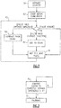
- a flowchart shown in Figure 2 improves upon this control.
- a counter is initialized, such as to zero.
- motor commutation is done in which the rotation of the permanent magnets on the rotor 28 is sensed by the several sensors 30.
- Sensors send pulses 46, as shown in Figure 1A . It is known to determine if a particular pulse is actually background noise or is an actual sensed pulse. As an example, this is disclosed in United States Reissue Patent 45,388 . Moreover, this patent discloses the basic position sensing as described. This sensing is incorporated into this application by reference.
- the count is comparted to an expected position count.
- the question is asked is the difference between the actual count and the expected position count greater than a predetermined value X. If not, then no action is taken. On the other hand, should the difference exceed the predetermined value X, then a calibration step 72 is taken.
- the value X may be selected to ensure there is not too much difference between actual and expected positions of the valve.
- Figure 1A also shows one embodiment of a calibration step.
- An item 80 on the component 42 is driven back against the stop 82. This then provides a zero position for the component 80 and the system can then move to drive the component 42 back towards a desired position, which becomes the expected position.
- Figure 1B shows another embodiment wherein a shaft 84, which may be either the shaft 32 or 38 from the Figure 1A system is provided with a permanent magnet 86.
- a sensor 88 which may be a Hall effect device, looks for the position of the magnet 86 and utilizes this position to again zero out or calibrate the location of the component 42 in the control 40. Then, the component 42 can be driven back toward a desired position.
Landscapes
- Engineering & Computer Science (AREA)
- General Engineering & Computer Science (AREA)
- Mechanical Engineering (AREA)
- Control Of Position Or Direction (AREA)
- Measurement Of Length, Angles, Or The Like Using Electric Or Magnetic Means (AREA)
Claims (10)
- Elektromechanisches System (20), umfassend:eine Komponente (42), die positioniert werden soll;einen Drehpermanentmagnetmotor (24) zum Positionieren der Komponente;Sensoren (30) zum Bestimmen einer scheinbaren Position der Komponente (42) auf Grundlage einer Drehung der Permanentmagneten; undein Steuerelement (40), das eine Bewegung der Permanentmagneten an den Sensoren (30) vorbei in einer erwünschten Richtung und auch eine Bewegung der Permanentmagneten an den Sensoren (30) vorbei in einer unerwünschten Richtung erfasst und einen Zählimpuls einer tatsächlichen Position der Komponente (42) auf Grundlage der beiden Drehungen vorbereitet, und wobei das Steuerelement (40) die Drehung der Permanentmagneten an den Sensoren (30) vorbei in einer unerwünschten Richtung erfasst, wenn der Motor (24) anhält, dadurch gekennzeichnet, dass das Steuerelement (40) zudem die tatsächliche Position mit einer erwarteten Position für die Komponente (42) vergleicht und eine Notwendigkeit zum Kalibrieren identifiziert, sollte sich ein Unterschied zwischen der tatsächlichen und der erwarteten Position um mehr als ein vorbestimmtes Ausmaß unterscheiden,wobei der Permanentmagnetmotor (24) dazu konfiguriert ist, eine erste Welle (32) anzutreiben, die ein erstes Zahnrad (34) aufweist, wobei das erste Zahnrad (34) mindestens ein zweites Zahnrad (36) antreibt, um wiederum eine zweite Welle (38) anzutreiben, die die Komponente (42) in einer Drehrichtung bewegt, wobei das erste und das zweite Zahnrad (34, 36) eine Drehzahl zwischen der ersten und der zweiten Welle (32, 38) ändern, undwobei jedes von der ersten und der zweiten Welle (32, 38) und Verzahnung zwischen dem ersten (34) und dem zweiten (36) Zahnrad eine Federkraft aufweist, die zu einer Drehung in der unerwünschten Richtung führen kann, wenn der Motor (24) anhält;wobei, falls die Kalibrierung als notwendig erachtet wird, eine Fläche an der Komponente (42) gegen einen Anschlag (82) getrieben wird, um eine neue erwartete Position in dem Steuerelement für die Komponente (42) bereitzustellen.
- Elektromechanisches System (20) nach Anspruch 1, wobei die Komponente (42) ein Ventil ist.
- Elektromechanisches System (20) nach Anspruch 1 oder 2, wobei die Sensoren (30) Hall-Effekt-Sensoren sind.
- Elektromechanisches System (20) nach einem der vorhergehenden Ansprüche, wobei die Komponente (42) an einem Raumfahrzeug montiert ist.
- Elektromechanisches System (20) nach einem der vorhergehenden Ansprüche, wobei das Steuerelement (40) dazu programmiert ist, zu bestimmen, ob ein Impuls von jedem der Sensoren (30) entweder ein ungültiger Impuls, ein tatsächlicher Impuls in der erwünschten Richtung oder ein tatsächlicher Impuls in der unerwünschten Richtung ist.
- Elektromechanisches System nach einem der vorhergehenden Ansprüche, wobei, falls die Kalibrierung als notwendig erachtet wird, ein Sensor (30) eine Stelle eines Merkmals erfasst und die Stelle des Merkmals dazu genutzt wird, eine neue erwartete Position in dem Steuerelement für die Komponente (42) bereitzustellen, und
wobei das Merkmal ein Permanentmagnet ist. - Verfahren, umfassend die folgenden Schritte:Antreiben eines Drehpermanentmagnetmotors (24) zum Positionieren einer Komponente;Bestimmen einer scheinbaren Position der Komponente durch Sensoren (30) auf Grundlage einer Drehung der Permanentmagneten an dem Sensor (30) vorbei; undErfassen einer Bewegung der Permanentmagneten an den Sensoren (30) vorbei in einer erwünschten Richtung und auch einer Bewegung der Permanentmagneten an den Sensoren vorbei in einer unerwünschten Richtung und Vorbereiten eines Zählimpulses einer tatsächlichen Position der Komponente (42) auf Grundlage der beiden Drehrichtungen und Vergleichen der tatsächlichen Position mit einer erwarteten Position der Komponente (42) und Identifizieren einer Notwendigkeit zum Kalibrieren, sollte sich ein Unterschied zwischen der berechneten und der erwarteten Position um mehr als ein vorbestimmtes Ausmaß unterscheiden, und wobei sich der Schritt zum Erfassen der Drehung der Permanentmagneten an den Sensoren vorbei in der unerwünschten Richtung ereignet, wenn der Motor (24) anhält;wobei der Permanentmagnetmotor (24) eine erste Welle (32) antreibt, die ein erstes Zahnrad (34) aufweist, wobei das erste Zahnrad (34) mindestens ein zweites Zahnrad (36) antreibt, um wiederum eine zweite Welle (38) anzutreiben, die die Komponente (42) in einer Drehrichtung bewegt, wobei das erste und das zweite Zahnrad (34, 36) eine Drehzahl zwischen der ersten und der zweiten Welle (32, 38) ändern, undwobei jedes von der ersten und der zweiten Welle (32, 38) und Verzahnung zwischen dem ersten (34) und dem zweiten (36) Zahnrad eine Federkraft aufweist, die zu einer Drehung in der unerwünschten Richtung führen kann, wenn der Motor (24) anhält;wobei, falls die Kalibrierung als notwendig erachtet wird, eine Fläche an der Komponente (42) gegen einen Anschlag (82) getrieben wird, um eine neue erwartete Position in dem Steuerelement für die Komponente (42) bereitzustellen.
- Verfahren nach Anspruch 7, wobei die Komponente (42) ein Ventil ist.
- Verfahren nach Anspruch 7 oder 8, wobei die Sensoren (30) Hall-Effekt-Sensoren sind und/oder wobei die Komponente (42) an einem Raumfahrzeug montiert ist.
- Verfahren nach einem der Ansprüche 7 bis 9, wobei ein Steuerelement (40) bestimmt, ob ein Impuls von jedem der Sensoren (30) entweder ein ungültiger Impuls, ein tatsächlicher Impuls in der erwünschten Richtung oder ein tatsächlicher Impuls in der unerwünschten Richtung ist.
Applications Claiming Priority (1)
| Application Number | Priority Date | Filing Date | Title |
|---|---|---|---|
| US15/455,174 US20180259091A1 (en) | 2017-03-10 | 2017-03-10 | Control valve positioning system |
Publications (2)
| Publication Number | Publication Date |
|---|---|
| EP3372882A1 EP3372882A1 (de) | 2018-09-12 |
| EP3372882B1 true EP3372882B1 (de) | 2021-07-07 |
Family
ID=61622375
Family Applications (1)
| Application Number | Title | Priority Date | Filing Date |
|---|---|---|---|
| EP18161008.0A Active EP3372882B1 (de) | 2017-03-10 | 2018-03-09 | Steuerventilpositioniersystem |
Country Status (2)
| Country | Link |
|---|---|
| US (1) | US20180259091A1 (de) |
| EP (1) | EP3372882B1 (de) |
Families Citing this family (2)
| Publication number | Priority date | Publication date | Assignee | Title |
|---|---|---|---|---|
| CN111457142B (zh) * | 2019-01-21 | 2022-04-22 | 杭州三花研究院有限公司 | 控制方法以及控制系统 |
| CN111076228A (zh) * | 2019-12-12 | 2020-04-28 | 华帝股份有限公司 | 一种灶具的档位判断方法 |
Family Cites Families (5)
| Publication number | Priority date | Publication date | Assignee | Title |
|---|---|---|---|---|
| US45388A (en) | 1864-12-13 | Improved coal-scuttle | ||
| US7049813B2 (en) * | 2004-01-09 | 2006-05-23 | Hr Textron Inc. | Motor state counting |
| US7374148B2 (en) * | 2006-02-22 | 2008-05-20 | I-Hua Huang | Control system for flow adjusting valve |
| US8294396B2 (en) * | 2009-07-13 | 2012-10-23 | Hamilton Sundstrand Space Systems International, Inc. | Compact FPGA-based digital motor controller |
| US9759737B2 (en) * | 2014-08-22 | 2017-09-12 | GM Global Technology Operations LLC | Method and apparatus for monitoring speed and position of a rotating member |
-
2017
- 2017-03-10 US US15/455,174 patent/US20180259091A1/en not_active Abandoned
-
2018
- 2018-03-09 EP EP18161008.0A patent/EP3372882B1/de active Active
Non-Patent Citations (1)
| Title |
|---|
| None * |
Also Published As
| Publication number | Publication date |
|---|---|
| US20180259091A1 (en) | 2018-09-13 |
| EP3372882A1 (de) | 2018-09-12 |
Similar Documents
| Publication | Publication Date | Title |
|---|---|---|
| JP6664995B2 (ja) | モーター制御方法 | |
| US7005814B2 (en) | Motor control apparatus having current supply phase correction | |
| US8412403B2 (en) | Method and device for increasing the precision of the position determination of a motor-driven closure element of a vehicle | |
| EP3372882A1 (de) | Steuerventilpositioniersystem | |
| EP0786710B1 (de) | Positionierungssystem mit Geschwindigkeitsregelung und Positionsregelung unter Verwendung des Geschwindigkeitsprofiles | |
| TWI660162B (zh) | 馬達控制裝置及使用該控制裝置之馬達裝置 | |
| JP2023528432A5 (de) | ||
| JP6371010B1 (ja) | 状態オブザーバ併用型フルクローズド制御による波動歯車装置を備えたアクチュエータの位置決め制御装置 | |
| EP3072759B1 (de) | Bremskraftmesstechniken | |
| CN106404032B (zh) | 控制编码器主轴速度同步的方法 | |
| US4757458A (en) | Zero point adjusting robot control method | |
| CN111457142B (zh) | 控制方法以及控制系统 | |
| KR20210055930A (ko) | Dc 모터 속도 조정기와 각가속도 추정 시스템 | |
| JP6874674B2 (ja) | シフトレンジ制御装置 | |
| CN102778860A (zh) | 位置控制装置的控制参数调整方法及控制参数调整系统 | |
| US20160072418A1 (en) | Method for precise position determination | |
| JP2006195566A (ja) | サーボ制御装置とその制御方法 | |
| US20080129549A1 (en) | System and method for encoder failure detection | |
| US11945314B2 (en) | Method for operating a drive train, and drive train | |
| US10704661B2 (en) | Actuator device having cam and follower and controller configured to employ rate-based methodology to identify positioning of follower on cam at predetermined location | |
| EP1462916B1 (de) | Kraftrückkopplungsdateneingabegerät | |
| JP4140139B2 (ja) | 負荷トルク推定方法及びトルク制御装置 | |
| JPH04336915A (ja) | Nc装置の歯合わせ方法 | |
| JP7552496B2 (ja) | 駆動装置の制御装置及び駆動システム | |
| EP3678290A1 (de) | Motoransteuerungsvorrichtung |
Legal Events
| Date | Code | Title | Description |
|---|---|---|---|
| PUAI | Public reference made under article 153(3) epc to a published international application that has entered the european phase |
Free format text: ORIGINAL CODE: 0009012 |
|
| STAA | Information on the status of an ep patent application or granted ep patent |
Free format text: STATUS: THE APPLICATION HAS BEEN PUBLISHED |
|
| AK | Designated contracting states |
Kind code of ref document: A1 Designated state(s): AL AT BE BG CH CY CZ DE DK EE ES FI FR GB GR HR HU IE IS IT LI LT LU LV MC MK MT NL NO PL PT RO RS SE SI SK SM TR |
|
| AX | Request for extension of the european patent |
Extension state: BA ME |
|
| STAA | Information on the status of an ep patent application or granted ep patent |
Free format text: STATUS: REQUEST FOR EXAMINATION WAS MADE |
|
| 17P | Request for examination filed |
Effective date: 20190226 |
|
| RBV | Designated contracting states (corrected) |
Designated state(s): AL AT BE BG CH CY CZ DE DK EE ES FI FR GB GR HR HU IE IS IT LI LT LU LV MC MK MT NL NO PL PT RO RS SE SI SK SM TR |
|
| STAA | Information on the status of an ep patent application or granted ep patent |
Free format text: STATUS: EXAMINATION IS IN PROGRESS |
|
| 17Q | First examination report despatched |
Effective date: 20190703 |
|
| GRAP | Despatch of communication of intention to grant a patent |
Free format text: ORIGINAL CODE: EPIDOSNIGR1 |
|
| STAA | Information on the status of an ep patent application or granted ep patent |
Free format text: STATUS: GRANT OF PATENT IS INTENDED |
|
| INTG | Intention to grant announced |
Effective date: 20210211 |
|
| GRAS | Grant fee paid |
Free format text: ORIGINAL CODE: EPIDOSNIGR3 |
|
| GRAA | (expected) grant |
Free format text: ORIGINAL CODE: 0009210 |
|
| STAA | Information on the status of an ep patent application or granted ep patent |
Free format text: STATUS: THE PATENT HAS BEEN GRANTED |
|
| AK | Designated contracting states |
Kind code of ref document: B1 Designated state(s): AL AT BE BG CH CY CZ DE DK EE ES FI FR GB GR HR HU IE IS IT LI LT LU LV MC MK MT NL NO PL PT RO RS SE SI SK SM TR |
|
| REG | Reference to a national code |
Ref country code: GB Ref legal event code: FG4D |
|
| REG | Reference to a national code |
Ref country code: AT Ref legal event code: REF Ref document number: 1408914 Country of ref document: AT Kind code of ref document: T Effective date: 20210715 |
|
| REG | Reference to a national code |
Ref country code: DE Ref legal event code: R096 Ref document number: 602018019547 Country of ref document: DE |
|
| REG | Reference to a national code |
Ref country code: IE Ref legal event code: FG4D |
|
| REG | Reference to a national code |
Ref country code: LT Ref legal event code: MG9D |
|
| REG | Reference to a national code |
Ref country code: NL Ref legal event code: MP Effective date: 20210707 |
|
| REG | Reference to a national code |
Ref country code: AT Ref legal event code: MK05 Ref document number: 1408914 Country of ref document: AT Kind code of ref document: T Effective date: 20210707 |
|
| PG25 | Lapsed in a contracting state [announced via postgrant information from national office to epo] |
Ref country code: RS Free format text: LAPSE BECAUSE OF FAILURE TO SUBMIT A TRANSLATION OF THE DESCRIPTION OR TO PAY THE FEE WITHIN THE PRESCRIBED TIME-LIMIT Effective date: 20210707 Ref country code: SE Free format text: LAPSE BECAUSE OF FAILURE TO SUBMIT A TRANSLATION OF THE DESCRIPTION OR TO PAY THE FEE WITHIN THE PRESCRIBED TIME-LIMIT Effective date: 20210707 Ref country code: ES Free format text: LAPSE BECAUSE OF FAILURE TO SUBMIT A TRANSLATION OF THE DESCRIPTION OR TO PAY THE FEE WITHIN THE PRESCRIBED TIME-LIMIT Effective date: 20210707 Ref country code: FI Free format text: LAPSE BECAUSE OF FAILURE TO SUBMIT A TRANSLATION OF THE DESCRIPTION OR TO PAY THE FEE WITHIN THE PRESCRIBED TIME-LIMIT Effective date: 20210707 Ref country code: HR Free format text: LAPSE BECAUSE OF FAILURE TO SUBMIT A TRANSLATION OF THE DESCRIPTION OR TO PAY THE FEE WITHIN THE PRESCRIBED TIME-LIMIT Effective date: 20210707 Ref country code: PT Free format text: LAPSE BECAUSE OF FAILURE TO SUBMIT A TRANSLATION OF THE DESCRIPTION OR TO PAY THE FEE WITHIN THE PRESCRIBED TIME-LIMIT Effective date: 20211108 Ref country code: NL Free format text: LAPSE BECAUSE OF FAILURE TO SUBMIT A TRANSLATION OF THE DESCRIPTION OR TO PAY THE FEE WITHIN THE PRESCRIBED TIME-LIMIT Effective date: 20210707 Ref country code: NO Free format text: LAPSE BECAUSE OF FAILURE TO SUBMIT A TRANSLATION OF THE DESCRIPTION OR TO PAY THE FEE WITHIN THE PRESCRIBED TIME-LIMIT Effective date: 20211007 Ref country code: LT Free format text: LAPSE BECAUSE OF FAILURE TO SUBMIT A TRANSLATION OF THE DESCRIPTION OR TO PAY THE FEE WITHIN THE PRESCRIBED TIME-LIMIT Effective date: 20210707 Ref country code: BG Free format text: LAPSE BECAUSE OF FAILURE TO SUBMIT A TRANSLATION OF THE DESCRIPTION OR TO PAY THE FEE WITHIN THE PRESCRIBED TIME-LIMIT Effective date: 20211007 Ref country code: AT Free format text: LAPSE BECAUSE OF FAILURE TO SUBMIT A TRANSLATION OF THE DESCRIPTION OR TO PAY THE FEE WITHIN THE PRESCRIBED TIME-LIMIT Effective date: 20210707 |
|
| PG25 | Lapsed in a contracting state [announced via postgrant information from national office to epo] |
Ref country code: PL Free format text: LAPSE BECAUSE OF FAILURE TO SUBMIT A TRANSLATION OF THE DESCRIPTION OR TO PAY THE FEE WITHIN THE PRESCRIBED TIME-LIMIT Effective date: 20210707 Ref country code: LV Free format text: LAPSE BECAUSE OF FAILURE TO SUBMIT A TRANSLATION OF THE DESCRIPTION OR TO PAY THE FEE WITHIN THE PRESCRIBED TIME-LIMIT Effective date: 20210707 Ref country code: GR Free format text: LAPSE BECAUSE OF FAILURE TO SUBMIT A TRANSLATION OF THE DESCRIPTION OR TO PAY THE FEE WITHIN THE PRESCRIBED TIME-LIMIT Effective date: 20211008 |
|
| REG | Reference to a national code |
Ref country code: DE Ref legal event code: R097 Ref document number: 602018019547 Country of ref document: DE |
|
| PG25 | Lapsed in a contracting state [announced via postgrant information from national office to epo] |
Ref country code: DK Free format text: LAPSE BECAUSE OF FAILURE TO SUBMIT A TRANSLATION OF THE DESCRIPTION OR TO PAY THE FEE WITHIN THE PRESCRIBED TIME-LIMIT Effective date: 20210707 |
|
| PLBE | No opposition filed within time limit |
Free format text: ORIGINAL CODE: 0009261 |
|
| STAA | Information on the status of an ep patent application or granted ep patent |
Free format text: STATUS: NO OPPOSITION FILED WITHIN TIME LIMIT |
|
| PG25 | Lapsed in a contracting state [announced via postgrant information from national office to epo] |
Ref country code: SM Free format text: LAPSE BECAUSE OF FAILURE TO SUBMIT A TRANSLATION OF THE DESCRIPTION OR TO PAY THE FEE WITHIN THE PRESCRIBED TIME-LIMIT Effective date: 20210707 Ref country code: SK Free format text: LAPSE BECAUSE OF FAILURE TO SUBMIT A TRANSLATION OF THE DESCRIPTION OR TO PAY THE FEE WITHIN THE PRESCRIBED TIME-LIMIT Effective date: 20210707 Ref country code: RO Free format text: LAPSE BECAUSE OF FAILURE TO SUBMIT A TRANSLATION OF THE DESCRIPTION OR TO PAY THE FEE WITHIN THE PRESCRIBED TIME-LIMIT Effective date: 20210707 Ref country code: EE Free format text: LAPSE BECAUSE OF FAILURE TO SUBMIT A TRANSLATION OF THE DESCRIPTION OR TO PAY THE FEE WITHIN THE PRESCRIBED TIME-LIMIT Effective date: 20210707 Ref country code: CZ Free format text: LAPSE BECAUSE OF FAILURE TO SUBMIT A TRANSLATION OF THE DESCRIPTION OR TO PAY THE FEE WITHIN THE PRESCRIBED TIME-LIMIT Effective date: 20210707 Ref country code: AL Free format text: LAPSE BECAUSE OF FAILURE TO SUBMIT A TRANSLATION OF THE DESCRIPTION OR TO PAY THE FEE WITHIN THE PRESCRIBED TIME-LIMIT Effective date: 20210707 |
|
| 26N | No opposition filed |
Effective date: 20220408 |
|
| PG25 | Lapsed in a contracting state [announced via postgrant information from national office to epo] |
Ref country code: IT Free format text: LAPSE BECAUSE OF FAILURE TO SUBMIT A TRANSLATION OF THE DESCRIPTION OR TO PAY THE FEE WITHIN THE PRESCRIBED TIME-LIMIT Effective date: 20210707 |
|
| PG25 | Lapsed in a contracting state [announced via postgrant information from national office to epo] |
Ref country code: MC Free format text: LAPSE BECAUSE OF FAILURE TO SUBMIT A TRANSLATION OF THE DESCRIPTION OR TO PAY THE FEE WITHIN THE PRESCRIBED TIME-LIMIT Effective date: 20210707 |
|
| REG | Reference to a national code |
Ref country code: CH Ref legal event code: PL |
|
| REG | Reference to a national code |
Ref country code: BE Ref legal event code: MM Effective date: 20220331 |
|
| PG25 | Lapsed in a contracting state [announced via postgrant information from national office to epo] |
Ref country code: LU Free format text: LAPSE BECAUSE OF NON-PAYMENT OF DUE FEES Effective date: 20220309 Ref country code: LI Free format text: LAPSE BECAUSE OF NON-PAYMENT OF DUE FEES Effective date: 20220331 Ref country code: IE Free format text: LAPSE BECAUSE OF NON-PAYMENT OF DUE FEES Effective date: 20220309 Ref country code: CH Free format text: LAPSE BECAUSE OF NON-PAYMENT OF DUE FEES Effective date: 20220331 |
|
| PG25 | Lapsed in a contracting state [announced via postgrant information from national office to epo] |
Ref country code: BE Free format text: LAPSE BECAUSE OF NON-PAYMENT OF DUE FEES Effective date: 20220331 |
|
| P01 | Opt-out of the competence of the unified patent court (upc) registered |
Effective date: 20230522 |
|
| PG25 | Lapsed in a contracting state [announced via postgrant information from national office to epo] |
Ref country code: HU Free format text: LAPSE BECAUSE OF FAILURE TO SUBMIT A TRANSLATION OF THE DESCRIPTION OR TO PAY THE FEE WITHIN THE PRESCRIBED TIME-LIMIT; INVALID AB INITIO Effective date: 20180309 |
|
| PG25 | Lapsed in a contracting state [announced via postgrant information from national office to epo] |
Ref country code: MK Free format text: LAPSE BECAUSE OF FAILURE TO SUBMIT A TRANSLATION OF THE DESCRIPTION OR TO PAY THE FEE WITHIN THE PRESCRIBED TIME-LIMIT Effective date: 20210707 Ref country code: CY Free format text: LAPSE BECAUSE OF FAILURE TO SUBMIT A TRANSLATION OF THE DESCRIPTION OR TO PAY THE FEE WITHIN THE PRESCRIBED TIME-LIMIT Effective date: 20210707 |
|
| PG25 | Lapsed in a contracting state [announced via postgrant information from national office to epo] |
Ref country code: MT Free format text: LAPSE BECAUSE OF FAILURE TO SUBMIT A TRANSLATION OF THE DESCRIPTION OR TO PAY THE FEE WITHIN THE PRESCRIBED TIME-LIMIT Effective date: 20210707 |
|
| PG25 | Lapsed in a contracting state [announced via postgrant information from national office to epo] |
Ref country code: TR Free format text: LAPSE BECAUSE OF FAILURE TO SUBMIT A TRANSLATION OF THE DESCRIPTION OR TO PAY THE FEE WITHIN THE PRESCRIBED TIME-LIMIT Effective date: 20210707 |
|
| PGFP | Annual fee paid to national office [announced via postgrant information from national office to epo] |
Ref country code: GB Payment date: 20260219 Year of fee payment: 9 |
|
| PGFP | Annual fee paid to national office [announced via postgrant information from national office to epo] |
Ref country code: DE Payment date: 20260219 Year of fee payment: 9 |
|
| PGFP | Annual fee paid to national office [announced via postgrant information from national office to epo] |
Ref country code: FR Payment date: 20260219 Year of fee payment: 9 |