EP3372657B1 - Device for performing a hydrothermal carbonisation reaction - Google Patents
Device for performing a hydrothermal carbonisation reaction Download PDFInfo
- Publication number
- EP3372657B1 EP3372657B1 EP17160428.3A EP17160428A EP3372657B1 EP 3372657 B1 EP3372657 B1 EP 3372657B1 EP 17160428 A EP17160428 A EP 17160428A EP 3372657 B1 EP3372657 B1 EP 3372657B1
- Authority
- EP
- European Patent Office
- Prior art keywords
- pulper
- tank
- biomass
- heat
- reaction
- Prior art date
- Legal status (The legal status is an assumption and is not a legal conclusion. Google has not performed a legal analysis and makes no representation as to the accuracy of the status listed.)
- Active
Links
Images

Classifications
-
- C—CHEMISTRY; METALLURGY
- C10—PETROLEUM, GAS OR COKE INDUSTRIES; TECHNICAL GASES CONTAINING CARBON MONOXIDE; FUELS; LUBRICANTS; PEAT
- C10L—FUELS NOT OTHERWISE PROVIDED FOR; NATURAL GAS; SYNTHETIC NATURAL GAS OBTAINED BY PROCESSES NOT COVERED BY SUBCLASSES C10G, C10K; LIQUEFIED PETROLEUM GAS; ADDING MATERIALS TO FUELS OR FIRES TO REDUCE SMOKE OR UNDESIRABLE DEPOSITS OR TO FACILITATE SOOT REMOVAL; FIRELIGHTERS
- C10L9/00—Treating solid fuels to improve their combustion
- C10L9/08—Treating solid fuels to improve their combustion by heat treatments, e.g. calcining
- C10L9/086—Hydrothermal carbonization
-
- C—CHEMISTRY; METALLURGY
- C10—PETROLEUM, GAS OR COKE INDUSTRIES; TECHNICAL GASES CONTAINING CARBON MONOXIDE; FUELS; LUBRICANTS; PEAT
- C10B—DESTRUCTIVE DISTILLATION OF CARBONACEOUS MATERIALS FOR PRODUCTION OF GAS, COKE, TAR, OR SIMILAR MATERIALS
- C10B53/00—Destructive distillation, specially adapted for particular solid raw materials or solid raw materials in special form
-
- B—PERFORMING OPERATIONS; TRANSPORTING
- B01—PHYSICAL OR CHEMICAL PROCESSES OR APPARATUS IN GENERAL
- B01J—CHEMICAL OR PHYSICAL PROCESSES, e.g. CATALYSIS OR COLLOID CHEMISTRY; THEIR RELEVANT APPARATUS
- B01J19/00—Chemical, physical or physico-chemical processes in general; Their relevant apparatus
- B01J19/24—Stationary reactors without moving elements inside
-
- C—CHEMISTRY; METALLURGY
- C10—PETROLEUM, GAS OR COKE INDUSTRIES; TECHNICAL GASES CONTAINING CARBON MONOXIDE; FUELS; LUBRICANTS; PEAT
- C10B—DESTRUCTIVE DISTILLATION OF CARBONACEOUS MATERIALS FOR PRODUCTION OF GAS, COKE, TAR, OR SIMILAR MATERIALS
- C10B53/00—Destructive distillation, specially adapted for particular solid raw materials or solid raw materials in special form
- C10B53/02—Destructive distillation, specially adapted for particular solid raw materials or solid raw materials in special form of cellulose-containing material
-
- C—CHEMISTRY; METALLURGY
- C10—PETROLEUM, GAS OR COKE INDUSTRIES; TECHNICAL GASES CONTAINING CARBON MONOXIDE; FUELS; LUBRICANTS; PEAT
- C10B—DESTRUCTIVE DISTILLATION OF CARBONACEOUS MATERIALS FOR PRODUCTION OF GAS, COKE, TAR, OR SIMILAR MATERIALS
- C10B57/00—Other carbonising or coking processes; Features of destructive distillation processes in general
-
- C—CHEMISTRY; METALLURGY
- C10—PETROLEUM, GAS OR COKE INDUSTRIES; TECHNICAL GASES CONTAINING CARBON MONOXIDE; FUELS; LUBRICANTS; PEAT
- C10L—FUELS NOT OTHERWISE PROVIDED FOR; NATURAL GAS; SYNTHETIC NATURAL GAS OBTAINED BY PROCESSES NOT COVERED BY SUBCLASSES C10G, C10K; LIQUEFIED PETROLEUM GAS; ADDING MATERIALS TO FUELS OR FIRES TO REDUCE SMOKE OR UNDESIRABLE DEPOSITS OR TO FACILITATE SOOT REMOVAL; FIRELIGHTERS
- C10L5/00—Solid fuels
- C10L5/40—Solid fuels essentially based on materials of non-mineral origin
- C10L5/44—Solid fuels essentially based on materials of non-mineral origin on vegetable substances
-
- B—PERFORMING OPERATIONS; TRANSPORTING
- B01—PHYSICAL OR CHEMICAL PROCESSES OR APPARATUS IN GENERAL
- B01J—CHEMICAL OR PHYSICAL PROCESSES, e.g. CATALYSIS OR COLLOID CHEMISTRY; THEIR RELEVANT APPARATUS
- B01J2219/00—Chemical, physical or physico-chemical processes in general; Their relevant apparatus
- B01J2219/00049—Controlling or regulating processes
- B01J2219/00051—Controlling the temperature
- B01J2219/00074—Controlling the temperature by indirect heating or cooling employing heat exchange fluids
- B01J2219/00087—Controlling the temperature by indirect heating or cooling employing heat exchange fluids with heat exchange elements outside the reactor
-
- B—PERFORMING OPERATIONS; TRANSPORTING
- B01—PHYSICAL OR CHEMICAL PROCESSES OR APPARATUS IN GENERAL
- B01J—CHEMICAL OR PHYSICAL PROCESSES, e.g. CATALYSIS OR COLLOID CHEMISTRY; THEIR RELEVANT APPARATUS
- B01J2219/00—Chemical, physical or physico-chemical processes in general; Their relevant apparatus
- B01J2219/00049—Controlling or regulating processes
- B01J2219/00051—Controlling the temperature
- B01J2219/00159—Controlling the temperature controlling multiple zones along the direction of flow, e.g. pre-heating and after-cooling
-
- C—CHEMISTRY; METALLURGY
- C10—PETROLEUM, GAS OR COKE INDUSTRIES; TECHNICAL GASES CONTAINING CARBON MONOXIDE; FUELS; LUBRICANTS; PEAT
- C10L—FUELS NOT OTHERWISE PROVIDED FOR; NATURAL GAS; SYNTHETIC NATURAL GAS OBTAINED BY PROCESSES NOT COVERED BY SUBCLASSES C10G, C10K; LIQUEFIED PETROLEUM GAS; ADDING MATERIALS TO FUELS OR FIRES TO REDUCE SMOKE OR UNDESIRABLE DEPOSITS OR TO FACILITATE SOOT REMOVAL; FIRELIGHTERS
- C10L2290/00—Fuel preparation or upgrading, processes or apparatus therefore, comprising specific process steps or apparatus units
- C10L2290/06—Heat exchange, direct or indirect
-
- C—CHEMISTRY; METALLURGY
- C10—PETROLEUM, GAS OR COKE INDUSTRIES; TECHNICAL GASES CONTAINING CARBON MONOXIDE; FUELS; LUBRICANTS; PEAT
- C10L—FUELS NOT OTHERWISE PROVIDED FOR; NATURAL GAS; SYNTHETIC NATURAL GAS OBTAINED BY PROCESSES NOT COVERED BY SUBCLASSES C10G, C10K; LIQUEFIED PETROLEUM GAS; ADDING MATERIALS TO FUELS OR FIRES TO REDUCE SMOKE OR UNDESIRABLE DEPOSITS OR TO FACILITATE SOOT REMOVAL; FIRELIGHTERS
- C10L2290/00—Fuel preparation or upgrading, processes or apparatus therefore, comprising specific process steps or apparatus units
- C10L2290/24—Mixing, stirring of fuel components
-
- Y—GENERAL TAGGING OF NEW TECHNOLOGICAL DEVELOPMENTS; GENERAL TAGGING OF CROSS-SECTIONAL TECHNOLOGIES SPANNING OVER SEVERAL SECTIONS OF THE IPC; TECHNICAL SUBJECTS COVERED BY FORMER USPC CROSS-REFERENCE ART COLLECTIONS [XRACs] AND DIGESTS
- Y02—TECHNOLOGIES OR APPLICATIONS FOR MITIGATION OR ADAPTATION AGAINST CLIMATE CHANGE
- Y02E—REDUCTION OF GREENHOUSE GAS [GHG] EMISSIONS, RELATED TO ENERGY GENERATION, TRANSMISSION OR DISTRIBUTION
- Y02E50/00—Technologies for the production of fuel of non-fossil origin
- Y02E50/10—Biofuels, e.g. bio-diesel
-
- Y—GENERAL TAGGING OF NEW TECHNOLOGICAL DEVELOPMENTS; GENERAL TAGGING OF CROSS-SECTIONAL TECHNOLOGIES SPANNING OVER SEVERAL SECTIONS OF THE IPC; TECHNICAL SUBJECTS COVERED BY FORMER USPC CROSS-REFERENCE ART COLLECTIONS [XRACs] AND DIGESTS
- Y02—TECHNOLOGIES OR APPLICATIONS FOR MITIGATION OR ADAPTATION AGAINST CLIMATE CHANGE
- Y02E—REDUCTION OF GREENHOUSE GAS [GHG] EMISSIONS, RELATED TO ENERGY GENERATION, TRANSMISSION OR DISTRIBUTION
- Y02E50/00—Technologies for the production of fuel of non-fossil origin
- Y02E50/30—Fuel from waste, e.g. synthetic alcohol or diesel
-
- Y—GENERAL TAGGING OF NEW TECHNOLOGICAL DEVELOPMENTS; GENERAL TAGGING OF CROSS-SECTIONAL TECHNOLOGIES SPANNING OVER SEVERAL SECTIONS OF THE IPC; TECHNICAL SUBJECTS COVERED BY FORMER USPC CROSS-REFERENCE ART COLLECTIONS [XRACs] AND DIGESTS
- Y02—TECHNOLOGIES OR APPLICATIONS FOR MITIGATION OR ADAPTATION AGAINST CLIMATE CHANGE
- Y02P—CLIMATE CHANGE MITIGATION TECHNOLOGIES IN THE PRODUCTION OR PROCESSING OF GOODS
- Y02P20/00—Technologies relating to chemical industry
- Y02P20/141—Feedstock
- Y02P20/145—Feedstock the feedstock being materials of biological origin
Definitions
- the present invention relates to a device for carrying out a hydrothermal Karbonmaschinesretress, comprising a reaction tank, which is connected for receiving superheated steam with a steam generator and for receiving biomass via a feed tube with a mixing tank and which for discharging a resulting in the reaction tank from superheated steam and biomass Slurry is connected to a buffer tank, wherein the mixing tank has a first heat exchanger for delivering heat to the biomass stored in the mixing tank, which with a buffer tank associated with the second heat exchanger for receiving heat from the reaction tank in the buffer tank drained slurry to a closed Heat circuit is connected, wherein the mixing tank and / or the buffer tank surrounded by at least one alongside enthusiaststragerschlange and / or are traversed.
- a hydrothermal carbonation reaction takes place in a reaction tank which is charged from a mixing tank or preheating tank.
- the mixing tank is connected via a solids pump with the reaction tank, which the biomass after a pretreatment with a lower compared to the reaction conditions in the reactor pressure and a lower temperature in the reactor promotes.
- Such a mixing tank is designed to more or less prepare a batch and then to be completely emptied into the reactor.
- the actual Karbonleitersretress then takes place in the reaction tank under a pressure of about 25 bar and at temperatures of 210 ° C to 230 ° C.
- the structures of the biomass are split in order to split the cellulose of the biomass into glucose as part of a hydrolysis.
- the actual carbonization takes place.
- a mixing of the biomass is here as well as a supply of superheated steam in order to increase the water content in the mixture and to form a slurry in which the carbonation reaction can proceed as effectively as possible.
- the initially water-soluble carbon components combine to form larger molecules.
- the former embodiment of the process provides a buffer tank into which the fully reacted slurry is removed from the reaction tank. There, the slurry is slowly cooled again at a lower pressure level.
- the process envisages converting biomass into the energy carrier biochar.
- as much energy as possible should be saved during the process, and it is also important to optimize the utilization of the system in order to work as effectively as possible in this regard.
- the object of the present invention is to further improve the energy balance and to make the process more effective.
- the invention provides as a solution to this problem, instead of a simple mixing tank to use a so-called pulper, more or less permanently store and prepare a complete day supply of biomass and thus can fill a reaction tank regularly.
- the biomass is already heated in the pulper and mixed, and preferably already mixed here superheated steam, so that the slurry already formed in the pulper and thus can be pumped very easily and quickly into the reaction tank. This reduces the downtime previously required for transporting the biomass via a solids pump into the reaction tank.
- Such heat exchangers can be realized in different ways.
- One possibility is to use the respective tank with a double-walled outer shell to surround.
- the resulting between the two outer walls hollow chamber can then be traversed by the heat transfer medium and absorb the heat depending on the location of either the interior of the two walls or give it to this.
- the pulper also has an agitator, it can be useful to carry the heat carrier in countercurrent to the resulting in the biomass flow due to the mixing.
- the respective tank may be traversed by one or more heat exchanger coils, which run through the interior of the respective tank or surround it and have as large a surface as possible due to windings and windings.
- the heat exchanger in the buffer tank would be a cooling coil, in the case of the heat exchanger in the pulper to a heating coil.
- a particularly suitable heat transfer medium is thermal oil, which is preferably used in the heat circuit.
- the pulper does not have to draw its heat solely from the heat circuit from the buffer tank.
- other sources for heating the pulper are needed.
- One step upstream of the buffer tank is excess heat from the reaction tank available, which in addition to the feed tube for supplying the slurry also has a gas pipe, via which it is connected to the pulper. If the pressure in the reaction tank is too high, excess gas, so-called purge gas, ie cleaning gas, can be released from the reaction tank, which is then brought into the pulper and raises the temperature there.
- purge gas ie cleaning gas
- a warming in the pulper must take place via a connection of the same to a steam generator.
- this may be the same steam generator that also feeds the reaction tank.
- the heating of the biomass in the pulper to its operating temperature of about 90 ° C can also be made uniform by the fact that the pulper means for mixing biomass and superheated steam are assigned.
- Such means may be stirring and mixing plants of different types, such as arrangements of mixing nozzles or a mechanical agitator with one or more Rlickarmen. Particular preference may be given to using an asymmetrical agitator which ensures that the biomass not only moves in a circle, but also forms turbulent flows.
- the purge gas can be introduced from the reaction tank into the pulper and thus contribute to the energy of the reaction tank both for heating and for mixing the biomass.
- the supply of superheated steam in the pulper also allows liquefaction of the biomass, so that it does not have to be spent with a solid pump in the reaction tank, but can be conveyed for example by a centrifugal pump. This allows a much faster feed of the reaction tank and thus reduces the life of the device between two batches. Furthermore, the centrifugal pump is also a cheaper alternative to the solids pump.
- pulper and / or the buffer tank may be useful not to manufacture the pulper and / or the buffer tank as a single construction, but rather to combine multiple tanks communicating with one another to form a pulper or a buffer tank.
- this can be used to combine low-priced tanks to a tank assembly, instead of building an expensive and very large special tank.
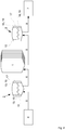
- FIG. 1 shows a schematic representation of a centrally arranged in the scheme reaction tank 1. This is connected via a feed tube 8 with a pulper 2, which feeds the reaction tank 1 with pretreated, liquefied biomass.
- the biomass in Pulper 2 comes from a bunker 6, in which large amounts of biomass are kept. Between the bunker 6 and the pulper 2 there is a conveyor unit and an impurity separation, in particular a metal separator, which processes the biomass for the pulper 2.
- an impurity separation in particular a metal separator
- a steam generator 4 which is connected to the pulper 2 via a steam pipe 11
- superheated steam is injected into the pulper 2, which heats the biomass contained in the pulper 2 on the one hand and adds water on the other hand to liquefy the biomass into a slurry.
- the slurry is mixed in the pulper 2, so that a uniform heating is ensured and the most homogeneous mixture possible.
- sand and silt will settle out of the biomass. These can be drained into a sand trap.
- reaction tank 1 at an overpressure via a gas pipe 10 so-called purge gas directly into the pulper 2, so that the escaping from the reaction tank 1 energy is retained in the system. Also, the reaction tank is fed via a steam pipe 12 from the steam generator 4 to produce the temperature required in the reaction tank 1, the required water and pressure, and thus to provide the reaction conditions for hydrothermal carbonization.
- the slurry with the carbonized biomass is discharged via a further feed pipe 8 into the buffer tank 3, which can take place via an at least partial pressure equalization between the reaction tank 1 and the buffer tank 3. Due to the pressure gradient between the two tanks 1 and 3, the slurry is sucked in this way very quickly into the buffer tank and can then cool down there. After cooling, the slurry passes through a further feed tube 8 for post-processing 7.
- process water separated from the process water 20 can be recycled back into the reaction tank 1, where a further reaction with the still contained organic loads of process water can be performed. In addition, this process water is used again in the process and does not need to be replaced by fresh water.
- the slurry in the pulper 2 and in the reaction tank 1 is heated and cooled in the buffer tank 3.
- the heat of the slurry in the buffer tank 3 can be transferred to the biomass in the pulper 2, so that less energy can escape from the system.
- This heat energy transferred to the pulper contributes to the fact that less superheated steam is needed to keep the pulper 2 at the required temperature.
- FIG. 2 shows a further schematic diagram in which possible heat exchangers 13 and 14 are shown.
- an outer shell 15 of the tanks 2, 3 double-walled it is possible to make an outer shell 15 of the tanks 2, 3 double-walled.
- a hollow chamber 16 is formed between the two walls, which may be covered on the outside with an insulating layer 17 in order to avoid heat losses.
- a first heat exchanger 13 in the pulper 2 releases the previously absorbed heat via the inner wall of the double-walled outer shell 15 and thereby heats the slurry received in the pulper 2 as it is in contact with the inner wall in question.
- the pulper 2 has a heating coil 18 which passes through the pulper 2 and also gives off heat to the slurry in its interior.
- a second heat exchanger 14 in the buffer tank 3 works in principle the same structure exactly the reverse, there takes the guided in the heat circuit 9 heat transfer heat energy from the cooling slurry and transports them through the heat circuit 9 through to the pulper 2. Accordingly, the heat exchanger coil also works as a cooling coil 19th
Landscapes
- Chemical & Material Sciences (AREA)
- Oil, Petroleum & Natural Gas (AREA)
- Organic Chemistry (AREA)
- Engineering & Computer Science (AREA)
- Materials Engineering (AREA)
- Physics & Mathematics (AREA)
- Thermal Sciences (AREA)
- Combustion & Propulsion (AREA)
- Chemical Kinetics & Catalysis (AREA)
- Processing Of Solid Wastes (AREA)
- Coke Industry (AREA)
Description
Die vorliegende Erfindung betrifft eine Vorrichtung zur Durchführung einer hydrothermalen Karbonisierungsreaktion, umfassend einen Reaktionstank, welcher zur Aufnahme von Heißdampf mit einem Dampfbereiter und zur Aufnahme von Biomasse über ein Zuführrohr mit einem Mischtank verbunden ist und welcher zum Ablassen eines in dem Reaktionstank aus Heißdampf und Biomasse entstehenden Slurry mit einem Puffertank verbunden ist, wobei der Mischtank einen ersten Wärmeübertrager zur Abgabe von Wärme an die in dem Mischtank vorgehaltene Biomasse aufweist, welcher mit einem dem Puffertank zugeordneten zweiten Wärmeübertrager zur Aufnahme von Wärme von aus dem Reaktionstank in den puffertank abgelassenem Slurry zu einem geschlossenen Wärmekreis verbunden ist, wobei der Mischtank und/oder der Puffertank von wenigstens einer Wärmeübertragerschlange umgeben und/oder durchzogen sind.The present invention relates to a device for carrying out a hydrothermal Karbonisierungsreaktion, comprising a reaction tank, which is connected for receiving superheated steam with a steam generator and for receiving biomass via a feed tube with a mixing tank and which for discharging a resulting in the reaction tank from superheated steam and biomass Slurry is connected to a buffer tank, wherein the mixing tank has a first heat exchanger for delivering heat to the biomass stored in the mixing tank, which with a buffer tank associated with the second heat exchanger for receiving heat from the reaction tank in the buffer tank drained slurry to a closed Heat circuit is connected, wherein the mixing tank and / or the buffer tank surrounded by at least one Wärmeübertragerschlange and / or are traversed.
Solche Vorrichtungen sind bereits aus der
Ferner ist eine derartige Vorrichtung bereits aus der
Die eigentliche Karbonisierungsreaktion findet dann im Reaktionstank unter einem Druck von etwa 25 bar und bei Temperaturen von 210°C bis 230°C statt. Zunächst werden hierbei die Strukturen der Biomasse aufgespalten, um im Rahmen einer Hydrolyse die Zellulose der Biomasse in Glukose aufzuspalten. Danach erfolgt die eigentliche Karbonisierung. Eine Durchmischung der Biomasse erfolgt hierbei ebenso wie eine Zuführung von Heißdampf, um den Wasseranteil in dem Gemisch zu erhöhen und einen Slurry zu bilden, in dem die Karbonisierungsreaktion möglichst effektiv ablaufen kann. Schließlich kombinieren sich im Rahmen der abschließenden Kondensation die zunächst wasserlöslichen Kohlenstoff-Bestandteile zu größeren Molekülen.The actual Karbonisierungsreaktion then takes place in the reaction tank under a pressure of about 25 bar and at temperatures of 210 ° C to 230 ° C. First, the structures of the biomass are split in order to split the cellulose of the biomass into glucose as part of a hydrolysis. Then the actual carbonization takes place. A mixing of the biomass is here as well as a supply of superheated steam in order to increase the water content in the mixture and to form a slurry in which the carbonation reaction can proceed as effectively as possible. Finally, in the course of the final condensation, the initially water-soluble carbon components combine to form larger molecules.
Nach der Reaktion sieht die frühere Ausgestaltung des Verfahrens einen Puffertank vor, in den der durchreagierte Slurry aus dem Reaktionstank verbracht wird. Dort wird der Slurry wiederum auf einem niedrigeren Druckniveau langsam abgekühlt.After the reaction, the former embodiment of the process provides a buffer tank into which the fully reacted slurry is removed from the reaction tank. There, the slurry is slowly cooled again at a lower pressure level.
Letztlich sieht das Verfahren vor, Biomasse in den Energieträger Biokohle umzuwandeln. Um möglichst effektiv zu arbeiten, soll möglichst viel Energie während des Verfahrens eingespart werden, zudem ist es wichtig, die Auslastung des Systems zu optimieren, um auch in dieser Hinsicht möglichst effektiv zu arbeiten.Ultimately, the process envisages converting biomass into the energy carrier biochar. In order to work as effectively as possible, as much energy as possible should be saved during the process, and it is also important to optimize the utilization of the system in order to work as effectively as possible in this regard.
Vor diesem Hintergrund liegt der vorliegenden Erfindung die Aufgabe zu Grunde, die Energiebilanz weiter zu verbessern und das Verfahren effektiver zu gestalten.Against this background, the object of the present invention is to further improve the energy balance and to make the process more effective.
Dies gelingt durch eine Vorrichtung zur Durchführung einer hydrothermalen Karbonisierungsreaktion gemäß den Merkmalen des Anspruchs 1. Weitere sinnvolle Ausgestaltungen einer solchen Vorrichtung können den sich anschließenden Unteransprüchen entnommen werden.This is achieved by a device for carrying out a hydrothermal Karbonisierungsreaktion according to the features of
Die Erfindung sieht als Lösung dieses Problems vor, anstelle eines einfachen Mischtanks einen so genannten Pulper einzusetzen, der mehr oder minder permanent einen vollständigen Tagesvorrat an Biomasse speichern und vorbereiten und damit einen Reaktionstank regelmäßig befüllen kann. Dazu wird die Biomasse bereits im Pulper erwärmt und durchmischt, sowie vorzugsweise auch bereits hier Heißdampf beigemischt, so dass der Slurry schon im Pulper entsteht und damit sehr leicht und schnell in den Reaktionstank gepumpt werden kann. Dies verringert die Standzeiten, die zuvor für den Transport der Biomasse per Feststoffpumpe in den Reaktionstank benötigt wurden.The invention provides as a solution to this problem, instead of a simple mixing tank to use a so-called pulper, more or less permanently store and prepare a complete day supply of biomass and thus can fill a reaction tank regularly. For this purpose, the biomass is already heated in the pulper and mixed, and preferably already mixed here superheated steam, so that the slurry already formed in the pulper and thus can be pumped very easily and quickly into the reaction tank. This reduces the downtime previously required for transporting the biomass via a solids pump into the reaction tank.
Besonders vorteilhaft ist aber vor allem die Verwendung eines ersten Wärmeübertragers, welcher in den Pulper integriert ist. Dieser bildet mit einem zweiten Wärmeübertrager, der in den Puffertank integriert ist und dort Wärme von dem aus dem Reaktor abgelassenen, durchreagierten Slurry aufnimmt, einen Wärmekreis. Die im Puffertank aufgenommene Wärme wird über den Wärmekreis zum Pulper transportiert und dort von der Biomasse aufgenommen. Das hierdurch wieder abkühlende Wärmemedium wird zurück zu dem zweiten Wärmeübertrager im Puffertank geleitet und kühlt dort wieder den Slurry, der seine Wärme auf das Wärmeträger überträgt.But especially advantageous is the use of a first heat exchanger, which is integrated into the pulper. This forms a heat circuit with a second heat exchanger, which is integrated into the buffer tank and absorbs heat therefrom from the thoroughly released, vented slurry from the reactor. The heat absorbed in the buffer tank is transported via the heat circuit to the pulper where it is absorbed by the biomass. The thereby again cooling heat medium is passed back to the second heat exchanger in the buffer tank and there again cools the slurry, which transfers its heat to the heat transfer medium.
Es entsteht dadurch ein Wärmekreislauf, bei dem der abkühlende Slurry seine Wärme auf die aufzuheizende Biomasse überträgt und somit die einmal in das System eingespeiste Energie nachhaltig im System hält. Ferner kann, um zusätzlich von außen eingreifen zu können, wenigstens ein weiterer Wärmeübertrager in dem Wärmekreis vorgesehen sein, über den gezielt Wärme in den Wärmekreis eingespeist oder aus diesem entnommen werden kann.This creates a heat cycle in which the cooling slurry transmits its heat to the biomass to be heated and thus keeps the energy once fed into the system sustainably in the system. Furthermore, in order additionally to be able to intervene from the outside, at least one further heat exchanger can be provided in the heat circuit, via which heat can be specifically fed into or removed from the heat circuit.
Solche Wärmeübertrager lassen sich auf unterschiedliche Weise realisieren. Eine Möglichkeit besteht darin, den jeweiligen Tank mit einer doppelwandigen Außenhülle zu umgeben. Die so zwischen den beiden Außenwänden entstehende Hohlkammer kann dann mit dem Wärmeträgermedium durchströmt werden und die Wärme je nach Einsatzort entweder von der Inneren der beiden Wände aufnehmen oder an diese abgeben. Soweit der Pulper zudem ein Rührwerk besitzt, kann es sinnvoll sein, das Wärmeträger im Gegenstrom zu dem sich aufgrund der Durchmischung ergebenden Strömung in der Biomasse zu führen.Such heat exchangers can be realized in different ways. One possibility is to use the respective tank with a double-walled outer shell to surround. The resulting between the two outer walls hollow chamber can then be traversed by the heat transfer medium and absorb the heat depending on the location of either the interior of the two walls or give it to this. If the pulper also has an agitator, it can be useful to carry the heat carrier in countercurrent to the resulting in the biomass flow due to the mixing.
Hierbei kann es sinnvoll sein, eine Isolationsschicht außen auf dem Pulper und dem Puffertank aufzubringen, um die Wärmeverluste durch Abstrahlung von dem Wärmeträgermedium zu verringern.It may be useful to apply an insulating layer on the outside of the pulper and the buffer tank in order to reduce the heat losses by radiation from the heat transfer medium.
Alternativ oder ergänzend kann der jeweilige Tank von einer oder mehreren Wärmeübertragerschlangen durchzogen sein, welche durch das Innere des jeweiligen Tanks verlaufen oder es umgeben und aufgrund von Windungen und Wicklungen eine möglichst große Oberfläche besitzen. Im Falle des Wärmeübertragers im Puffertank würde es sich um eine Kühlschlange, im Falle des Wärmeübertragers im Pulper um eine Heizschlange handeln. Ein besonders geeignetes Wärmeträger ist Thermoöl, welches in dem Wärmekreis bevorzugt eingesetzt wird.Alternatively or additionally, the respective tank may be traversed by one or more heat exchanger coils, which run through the interior of the respective tank or surround it and have as large a surface as possible due to windings and windings. In the case of the heat exchanger in the buffer tank would be a cooling coil, in the case of the heat exchanger in the pulper to a heating coil. A particularly suitable heat transfer medium is thermal oil, which is preferably used in the heat circuit.
Der Pulper muss seine Wärme jedoch nicht ausschließlich über den Wärmekreis aus dem Puffertank beziehen. Insbesondere beim Anfahren des Systems, wenn noch kein Slurry zum Abkühlen bereitsteht, werden andere Quellen für die Beheizung des Pulpers benötigt.However, the pulper does not have to draw its heat solely from the heat circuit from the buffer tank. In particular, when starting the system, when no slurry is still available for cooling, other sources for heating the pulper are needed.
Einen Schritt vor dem Puffertank steht überschüssige Wärme aus dem Reaktionstank zur Verfügung, welcher neben dem Zuführrohr zur Zuführung des Slurry auch ein Gasrohr aufweist, über welches er mit dem Pulper verbunden ist. Bei einem zu hohen Druck im Reaktionstank kann hierüber überschüssiges Gas, so genanntes Purgegas, also Reinigungsgas, aus dem Reaktionstank abgelassen werden, das in den Pulper verbracht wird und dort die Temperatur anhebt.One step upstream of the buffer tank is excess heat from the reaction tank available, which in addition to the feed tube for supplying the slurry also has a gas pipe, via which it is connected to the pulper. If the pressure in the reaction tank is too high, excess gas, so-called purge gas, ie cleaning gas, can be released from the reaction tank, which is then brought into the pulper and raises the temperature there.
Initial muss eine Erwärmung im Pulper jedoch über einen Anschluss desselben an einen Dampfbereiter erfolgen. Idealerweise kann dies derselbe Dampfbereiter sein, der auch den Reaktionstank speist. Durch die Zuführung von Heißdampf in den Pulper wird der größte Teil der erforderlichen Energie zum Aufheizen der Biomasse im Pulper bereitgestellt.Initially, however, a warming in the pulper must take place via a connection of the same to a steam generator. Ideally, this may be the same steam generator that also feeds the reaction tank. By supplying superheated steam into the pulper, most of the energy required to heat the biomass in the pulper is provided.
Die Aufheizung der Biomasse im Pulper auf seine Betriebstemperatur von um die 90°C kann zudem dadurch vergleichmäßigt werden, dass dem Pulper Mittel zum Durchmischen von Biomasse und Heißdampf zugeordnet werden. Solche Mittel können Rühr- und Mischwerke unterschiedlicher Art sein, etwa Anordnungen von Mischdüsen oder auch ein mechanisches Rührwerk mit einem oder mehreren Rührarmen. Besonders bevorzugt kann ein asymmetrisches Rührwerk eingesetzt werden, welches dafür sorgt, dass die Biomasse nicht nur im Kreis bewegt, sondern auch turbulente Strömungen ausbildet. Im Falle der Anordnung von Mischdüsen in dem Pulper kann insbesondere das Purgegas aus dem Reaktionstank in den Pulper eingebracht werden und so die Energie des Reaktionstanks sowohl zum Beheizen als auch zum Durchmischen der Biomasse beitragen.The heating of the biomass in the pulper to its operating temperature of about 90 ° C can also be made uniform by the fact that the pulper means for mixing biomass and superheated steam are assigned. Such means may be stirring and mixing plants of different types, such as arrangements of mixing nozzles or a mechanical agitator with one or more Rührarmen. Particular preference may be given to using an asymmetrical agitator which ensures that the biomass not only moves in a circle, but also forms turbulent flows. In the case of the arrangement of mixing nozzles in the pulper, in particular, the purge gas can be introduced from the reaction tank into the pulper and thus contribute to the energy of the reaction tank both for heating and for mixing the biomass.
Die Zuführung von Heißdampf in den Pulper erlaubt zudem eine Verflüssigung der Biomasse, so dass diese nicht mit einer Feststoffpumpe in den Reaktionstank verbracht werden muss, sondern beispielsweise durch eine Zentrifugalpumpe befördert werden kann. Dies erlaubt eine deutlich schnellere Beschickung des Reaktionstanks und reduziert damit die Standzeit der Vorrichtung zwischen zwei Batches. Ferner stellt die Zentrifugalpumpe auch eine kostengünstigere Alternative zur Feststoffpumpe dar.The supply of superheated steam in the pulper also allows liquefaction of the biomass, so that it does not have to be spent with a solid pump in the reaction tank, but can be conveyed for example by a centrifugal pump. This allows a much faster feed of the reaction tank and thus reduces the life of the device between two batches. Furthermore, the centrifugal pump is also a cheaper alternative to the solids pump.
In konkreter Ausgestaltung des Pulpers kann dieser einen trichterförmigen Boden besitzen, über den schwere Bestandteile aus der Biomasse abgeschieden werden. Am Boden werden sich Sand und Schlick absetzen, die über eine Ablassöffnung an der Trichterspitze in Richtung eines Sandabscheiders aus dem Pulper ausgetragen werden.In concrete embodiment of the pulper this may have a funnel-shaped bottom over which heavy components are separated from the biomass. At the bottom, sand and silt will settle, which will be discharged from the pulper via a discharge opening at the funnel tip in the direction of a sand separator.
Schließlich ist es im Sinne einer idealen Auslastung sinnvoll, mehrere Reaktionstanks mit einem gemeinsamen Pulper zu verbinden. Hierdurch kann während der Reaktionszeit eines ersten Reaktionstanks die Befüllung des nächsten Reaktionstanks beginnen, so lange bis der erste Reaktionstank wieder entleert wird und seine Beschickung mit Biomasse erneut beginnen kann. Vorzugsweise werden von einem Pulper dadurch etwa sechs Reaktionstanks bedient. Auch für die Puffertanks gilt dasselbe, vorzugsweise werden zwei Puffertanks den durchreagierten Slurry der sechs Reaktionstanks alternativ zueinander aufnehmen.Finally, it makes sense in the sense of an ideal utilization to connect several reaction tanks with a common pulper. As a result, the filling of the next reaction tank can begin during the reaction time of a first reaction tank, until the first reaction tank is emptied again and its biomass feed can start again. Preferably, about six reaction tanks are thereby served by one pulper. The same applies to the buffer tanks, preferably two buffer tanks will alternatively receive the fully reacted slurry of the six reaction tanks.
Ferner kann es in der praktischen Umsetzung sinnvoll sein, den Pulper und/oder den Puffertank nicht als eine einzelne Konstruktion herzustellen, sondern vielmehr mehrere miteinander kommunizierende Tanks zu einem Pulper bzw. einem Puffertank zu kombinieren. Insbesondere lassen sich dadurch günstig erwerbliche Tanks zu einer Tankanordnung kombinieren, anstatt einen teueren und besonders großen Spezialtank zu bauen.Further, in practice, it may be useful not to manufacture the pulper and / or the buffer tank as a single construction, but rather to combine multiple tanks communicating with one another to form a pulper or a buffer tank. In particular, this can be used to combine low-priced tanks to a tank assembly, instead of building an expensive and very large special tank.
Die vorstehend beschriebene Erfindung wird im Folgenden anhand eines Ausführungsbeispiels näher erläutert.The invention described above will be explained in more detail below with reference to an embodiment.
Es zeigen
Figur 1- eine schematische Darstellung der Funktionsweise einer erfindungsgemäßen Vorrichtung, sowie
Figur 2- eine schematische Darstellung des Wärmekreises sowie der Slurryzuführung.
- FIG. 1
- a schematic representation of the operation of a device according to the invention, and
- FIG. 2
- a schematic representation of the heat circuit and the slurry feed.
Zur Einsparung von Wärmeenergie wird der Reaktionstank 1 bei einem Überdruck über ein Gasrohr 10 so genanntes Purgegas direkt in den Pulper 2 abgeben, so dass die aus dem Reaktionstank 1 entweichende Energie im System erhalten bleibt. Auch der Reaktionstank wird über ein Dampfrohr 12 von dem Dampfbereiter 4 gespeist, um die im Reaktionstank 1 erforderliche Temperatur, das benötigte Wasser und den erforderlichen Druck zu erzeugen, und so die Reaktionsbedingungen für eine hydrothermale Karbonisierung zu schaffen.To save heat energy, the
Nach der Reaktion im Reaktionstank 1 wird der Slurry mit der karbonisierten Biomasse über ein weiteres Zuführrohr 8 in den Puffertank 3 abgelassen, wobei dies über einen zumindest teilweisen Druckausgleich zwischen Reaktionstank 1 und Puffertank 3 erfolgen kann. Aufgrund des Druckgefälles zwischen den beiden Tanks 1 und 3 wird der Slurry auf diese Weise sehr schnell in den Puffertank eingesaugt und kann dort anschließend abkühlen. Nach der Abkühlung gelangt der Slurry über ein weiteres Zuführrohr 8 zur Nachbereitung 7. Im Zuge weiterer, hier nicht im Einzelnen betrachteter Verfahren kann aus dem Slurry abgeschiedenes Prozesswasser 20 wieder in den Reaktionstank 1 zurückgeführt werden, wo eine weitere Reaktion mit den noch enthaltenen organischen Frachten des Prozesswassers durchgeführt werden kann. Zudem wird hierdurch das Prozesswasser wieder im Prozess eingesetzt und muss nicht durch Frischwasser ersetzt werden.After the reaction in the
Insgesamt ergibt sich, dass der Slurry im Pulper 2 und im Reaktionstank 1 erwärmt und im Puffertank 3 abgekühlt wird. Durch Wärmeübertrager in den beiden Tanks 2 und 3, die einen Wärmekreis 9 zwischen diesen beiden Tanks 2 und 3 ausbilden, kann die Hitze des Slurry im Puffertank 3 auf die Biomasse im Pulper 2 übertragen werden, so dass weniger Energie aus dem System entweichen kann. Diese an den Pulper übertragene Wärmeenergie trägt dazu bei, dass weniger Heißdampf benötigt wird, um den Pulper 2 auf der erforderlichen Temperatur zu halten.Overall, it follows that the slurry in the
Ein erster Wärmetauscher 13 im Pulper 2 gibt die zuvor aufgenommene Wärme über die innere Wand der doppelwandigen Außenhülle 15 ab und erwärmt dadurch den im Pulper 2 aufgenommenen Slurry bei dessen Kontakt mit der fraglichen inneren Wand. Zusätzlich weist der Pulper 2 eine Heizschlange 18 auf, die durch den Pulper 2 hindurchläuft und auch in dessen Innerem Wärme an den Slurry abgibt.A first heat exchanger 13 in the
Ein zweiter Wärmetauscher 14 im Puffertank 3 arbeitet bei prinzipiell gleichem Aufbau genau umgekehrt, dort nimmt der in dem Wärmekreis 9 geführte Wärmeträger Wärmeenergie von dem abkühlenden Slurry auf und transportiert diese durch den Wärmekreis 9 hindurch zum Pulper 2. Entsprechend funktioniert die Wärmeübertragerschlange hier auch als Kühlschlange 19.A second heat exchanger 14 in the
Vorstehend beschrieben ist somit eine Vorrichtung zur Durchführung einer hydrothermalen Karbonisierungsreaktion, welche durch den Einsatz von Wärmeübertragern und dem Transport von Wärme durch das System die Energiebilanz zu verbessern und durch ein Vorheizen und Verflüssigen der Biomasse bereits im Pulper das Verfahren effektiver zu gestalten.Thus, what has been described above is a device for carrying out a hydrothermal carbonization reaction, which improves the energy balance through the use of heat exchangers and the transport of heat through the system and makes the process more effective already in the pulper by preheating and liquefying the biomass.
- 11
- Reaktionstankreaction tank
- 22
- Pulperpulper
- 33
- Puffertankbuffer tank
- 44
- Dampfbereitersteam heaters
- 55
- SandabscheiderSandSeparator
- 66
- Bunkerbunker
- 77
- Nachbereitungpostprocessing
- 88th
- Zuführrohrfeed
- 99
- Wärmekreisheat circuit
- 1010
- Gasrohrgas pipe
- 1111
- Dampfrohrsteam pipe
- 1212
- Dampfrohrsteam pipe
- 1313
- erster Wärmeübertragerfirst heat exchanger
- 1414
- zweiter Wärmeübertragersecond heat exchanger
- 1515
- Außenhülleouter shell
- 1616
- Hohlkammerhollow
- 1717
- Isolationsschichtinsulation layer
- 1818
- Heizschlangeheating coil
- 1919
- Kühlschlangecooling coil
- 2020
- ProzesswasserrückführungProcess water recycling
Claims (9)
- A device for carrying out a hydrothermal carbonization reaction, comprising a reaction tank (1), which for receiving superheated steam is connected to a steam provider (4), and for receiving biomass is connected to a mixing tank via a feed tube (8), and which for discharging slurry formed in the reaction tank (1) from superheated steam and biomass is connected to a buffer tank (3), wherein the mixing tank has a first heat exchanger (13) for delivering heat to the biomass held in the mixing tank, the first heat exchanger being connected to a second heat exchanger (14), associated with the buffer tank (3), for receiving heat from the slurry that is discharged from the reaction tank (1) into the buffer tank (3) to form a closed thermal circuit (9), wherein at least one heat exchanger coil (18) surrounds or passes through the mixing tank and/or the buffer tank (3),
characterized in that the mixing tank is designed as a pulper (2) in which thermal oil as heat transfer medium is conducted in the closed thermal circuit (9), and at least a third heat exchanger via which heat is removable from the thermal circuit (9) and/or suppliable into the thermal circuit (9) in a targeted manner is associated with the thermal circuit (9). - The device according to one of the preceding claims, characterized in that the pulper (2) is connected to the feed tube (8), and also to the reaction tank (1) via a gas tube (10), and is feedable with cleaning gas that is discharged from the reaction tank (1).
- The device according to one of the preceding claims, characterized in that for supplying superheated steam, the pulper (2) is connected to the steam provider (4) via a steam tube (11).
- The device according to Claim 3, characterized in that the pulper (2) has means for mixing biomass and superheated steam.
- The device according to Claim 4, characterized in that the means for mixing biomass and superheated steam is an asymmetrical agitator and/or a mixing nozzle system.
- The device according to one of Claims 3 to 5, characterized in that a centrifugal pump is associated with the feed tube (8) between the pulper (2) and the reaction tank (1).
- The device according to one of the preceding claims, characterized in that the pulper (2) has a funnel-shaped base for depositing sand and sludge, wherein an outlet associated with the funnel tip is connected to a sand separator (5).
- The device according to one of the preceding claims, characterized in that multiple parallel, identical reaction tanks (1) are associated with a pulper (2).
- The device according to one of the preceding claims, characterized in that the pulper (2) and/or the buffer tank (3) are/is produced from multiple, preferably identical, tank units that communicate with one another.
Priority Applications (7)
| Application Number | Priority Date | Filing Date | Title |
|---|---|---|---|
| DK17160428.3T DK3372657T3 (en) | 2017-03-10 | 2017-03-10 | DEVICE FOR PERFORMING A HYDROTERMIC CARBONIZATION REACTION |
| EP17160428.3A EP3372657B1 (en) | 2017-03-10 | 2017-03-10 | Device for performing a hydrothermal carbonisation reaction |
| US15/596,579 US10113129B2 (en) | 2017-03-10 | 2017-05-16 | Apparatus for conducting a hydrothermal carbonization reaction |
| BR102017010693A BR102017010693A2 (en) | 2017-03-10 | 2017-05-22 | device for performing a hydrothermal carbonization reaction |
| CN201710473595.6A CN107345146B (en) | 2017-03-10 | 2017-06-21 | Device for carrying out hydrothermal carbonization reaction |
| SG10201800706QA SG10201800706QA (en) | 2017-03-10 | 2018-01-26 | Apparatus for conducting a hydrothermal carbonisation reaction |
| JP2018040614A JP6942311B2 (en) | 2017-03-10 | 2018-03-07 | Equipment for performing hydrothermal carbonization reaction |
Applications Claiming Priority (1)
| Application Number | Priority Date | Filing Date | Title |
|---|---|---|---|
| EP17160428.3A EP3372657B1 (en) | 2017-03-10 | 2017-03-10 | Device for performing a hydrothermal carbonisation reaction |
Publications (2)
| Publication Number | Publication Date |
|---|---|
| EP3372657A1 EP3372657A1 (en) | 2018-09-12 |
| EP3372657B1 true EP3372657B1 (en) | 2019-09-25 |
Family
ID=58412857
Family Applications (1)
| Application Number | Title | Priority Date | Filing Date |
|---|---|---|---|
| EP17160428.3A Active EP3372657B1 (en) | 2017-03-10 | 2017-03-10 | Device for performing a hydrothermal carbonisation reaction |
Country Status (7)
| Country | Link |
|---|---|
| US (1) | US10113129B2 (en) |
| EP (1) | EP3372657B1 (en) |
| JP (1) | JP6942311B2 (en) |
| CN (1) | CN107345146B (en) |
| BR (1) | BR102017010693A2 (en) |
| DK (1) | DK3372657T3 (en) |
| SG (1) | SG10201800706QA (en) |
Cited By (1)
| Publication number | Priority date | Publication date | Assignee | Title |
|---|---|---|---|---|
| DE102021129783A1 (en) | 2021-11-16 | 2023-05-17 | Gesellschaft zur Förderung von Medizin-, Bio- und Umwelttechnologien e.V. | Process for the production of sorption materials from fermentation residues in a biogas plant |
Families Citing this family (6)
| Publication number | Priority date | Publication date | Assignee | Title |
|---|---|---|---|---|
| CN109351297B (en) * | 2018-11-29 | 2023-10-17 | 清华大学 | Hydrothermal reaction system and operation method thereof |
| IT201800020320A1 (en) * | 2018-12-20 | 2020-06-20 | Daniele Basso | Plant and process for the transformation of biomass |
| CN113801669A (en) * | 2020-06-15 | 2021-12-17 | 清华大学山西清洁能源研究院 | High-water-content biomass continuous hydrothermal carbonization system and method |
| KR102422280B1 (en) * | 2021-11-17 | 2022-07-18 | 고등기술연구원연구조합 | System for recovering double heat exchanging energy of hydrothermal carbonization and method therefor |
| CN116146960B (en) * | 2021-11-23 | 2024-06-04 | 洛阳瑞昌环境工程有限公司 | Thermochemical heat accumulation energy storage heat supply system and energy storage heat supply method |
| CN115007063A (en) * | 2022-06-20 | 2022-09-06 | 无锡市检验检测认证研究院 | Biomass fuel preparation system and technology |
Citations (8)
| Publication number | Priority date | Publication date | Assignee | Title |
|---|---|---|---|---|
| DE102007062810A1 (en) | 2006-12-28 | 2008-07-17 | Dominik Peus | Substance or fuel for producing energy from biomass, is manufactured from biomass, which has higher carbon portion in comparison to raw material concerning percentaged mass portion of elements |
| DE102009022364A1 (en) | 2009-05-22 | 2010-11-25 | Addlogic Labs Gmbh | Device for the hydrothermal carbonization of biomass |
| WO2011117837A2 (en) | 2010-03-24 | 2011-09-29 | Antacor Pte. Ltd. | Method and device for treating solid-fluid mixtures |
| US8043505B2 (en) * | 2005-04-27 | 2011-10-25 | Enertech Environmental, Inc. | Treatment equipment of organic waste and treatment method |
| DE102010044200A1 (en) | 2010-07-23 | 2012-01-26 | Addlogic Labs Gmbh | Plant for exothermic high-pressure wet chemical reactions |
| WO2016071828A1 (en) | 2014-11-04 | 2016-05-12 | Degremont | Method for the hydrothermal carbonisation of a biomass and associated device |
| WO2016071808A1 (en) | 2014-11-04 | 2016-05-12 | Degremont | Method for the hydrothermal carbonisation of a biomass and associated device |
| US9556384B2 (en) | 2011-06-09 | 2017-01-31 | Ingelia, S.L. | Method for extracting biochemical products obtained from a process of hydrothermal carbonization of biomass |
Family Cites Families (9)
| Publication number | Priority date | Publication date | Assignee | Title |
|---|---|---|---|---|
| US6955793B1 (en) * | 1997-06-18 | 2005-10-18 | Arencibia Jr Jose P | Temperature controlled reaction vessel |
| US7909895B2 (en) * | 2004-11-10 | 2011-03-22 | Enertech Environmental, Inc. | Slurry dewatering and conversion of biosolids to a renewable fuel |
| CA2759130C (en) * | 2009-04-30 | 2018-03-13 | Eve Research Inc. | Preparation of biofuels and other useful products such as 5-(hydroxymethyl)-furfural |
| US8597431B2 (en) * | 2009-10-05 | 2013-12-03 | Andritz (Usa) Inc. | Biomass pretreatment |
| DE102011001108B4 (en) | 2011-03-04 | 2015-03-12 | Ava-Co2 Schweiz Ag | Method and device for hydrothermal carbonization |
| DE202011110245U1 (en) | 2011-04-11 | 2013-04-24 | Orfist AG | Reaction tank for carrying out a hydrothermal carbonation reaction |
| DE102011055990A1 (en) * | 2011-12-02 | 2013-06-06 | Thomas Reichhart | Method and device for the hydrothermal carbonization of biomass |
| WO2014178831A1 (en) * | 2013-04-30 | 2014-11-06 | Empire Technology Development Llc | Systems and methods for reducing corrosion in a reactor system |
| CN103755124A (en) * | 2014-01-23 | 2014-04-30 | 杭州互惠环保科技有限公司 | Sludge treatment method based on hydrothermal carbonization |
-
2017
- 2017-03-10 EP EP17160428.3A patent/EP3372657B1/en active Active
- 2017-03-10 DK DK17160428.3T patent/DK3372657T3/en active
- 2017-05-16 US US15/596,579 patent/US10113129B2/en active Active
- 2017-05-22 BR BR102017010693A patent/BR102017010693A2/en active Search and Examination
- 2017-06-21 CN CN201710473595.6A patent/CN107345146B/en not_active Expired - Fee Related
-
2018
- 2018-01-26 SG SG10201800706QA patent/SG10201800706QA/en unknown
- 2018-03-07 JP JP2018040614A patent/JP6942311B2/en active Active
Patent Citations (8)
| Publication number | Priority date | Publication date | Assignee | Title |
|---|---|---|---|---|
| US8043505B2 (en) * | 2005-04-27 | 2011-10-25 | Enertech Environmental, Inc. | Treatment equipment of organic waste and treatment method |
| DE102007062810A1 (en) | 2006-12-28 | 2008-07-17 | Dominik Peus | Substance or fuel for producing energy from biomass, is manufactured from biomass, which has higher carbon portion in comparison to raw material concerning percentaged mass portion of elements |
| DE102009022364A1 (en) | 2009-05-22 | 2010-11-25 | Addlogic Labs Gmbh | Device for the hydrothermal carbonization of biomass |
| WO2011117837A2 (en) | 2010-03-24 | 2011-09-29 | Antacor Pte. Ltd. | Method and device for treating solid-fluid mixtures |
| DE102010044200A1 (en) | 2010-07-23 | 2012-01-26 | Addlogic Labs Gmbh | Plant for exothermic high-pressure wet chemical reactions |
| US9556384B2 (en) | 2011-06-09 | 2017-01-31 | Ingelia, S.L. | Method for extracting biochemical products obtained from a process of hydrothermal carbonization of biomass |
| WO2016071828A1 (en) | 2014-11-04 | 2016-05-12 | Degremont | Method for the hydrothermal carbonisation of a biomass and associated device |
| WO2016071808A1 (en) | 2014-11-04 | 2016-05-12 | Degremont | Method for the hydrothermal carbonisation of a biomass and associated device |
Non-Patent Citations (2)
| Title |
|---|
| ANONYMOUS: "Pulper", WIKIPEDIA, 29 January 2019 (2019-01-29), pages 1 - 2, XP055761836 |
| ANONYMOUS: "Wärmetauscher", WIKIPEDIA, 28 May 2020 (2020-05-28), pages 1, XP055761829 |
Cited By (1)
| Publication number | Priority date | Publication date | Assignee | Title |
|---|---|---|---|---|
| DE102021129783A1 (en) | 2021-11-16 | 2023-05-17 | Gesellschaft zur Förderung von Medizin-, Bio- und Umwelttechnologien e.V. | Process for the production of sorption materials from fermentation residues in a biogas plant |
Also Published As
| Publication number | Publication date |
|---|---|
| US10113129B2 (en) | 2018-10-30 |
| DK3372657T3 (en) | 2020-01-27 |
| BR102017010693A2 (en) | 2018-10-30 |
| US20180258360A1 (en) | 2018-09-13 |
| JP2018159058A (en) | 2018-10-11 |
| SG10201800706QA (en) | 2018-10-30 |
| JP6942311B2 (en) | 2021-09-29 |
| EP3372657A1 (en) | 2018-09-12 |
| CN107345146B (en) | 2020-07-21 |
| CN107345146A (en) | 2017-11-14 |
Similar Documents
| Publication | Publication Date | Title |
|---|---|---|
| EP3372657B1 (en) | Device for performing a hydrothermal carbonisation reaction | |
| EP2681296B1 (en) | Method and device for hydrothermal carbonization | |
| DE2839663A1 (en) | DEVICE AND METHOD FOR HEAT TREATING ORGANIC CARBON MATERIAL | |
| AT507469B1 (en) | DEVICE FOR CONTINUOUS OR DISCONTINUOUS HYDROLYSIS OF ORGANIC SUBSTRATES | |
| DE3543582A1 (en) | REACTOR WITH SEVERAL FOCUS ELEMENTS AND METHOD FOR THE THERMAL TREATMENT OF CARBONATED MATERIALS | |
| DE112006003092T5 (en) | Process and apparatus for producing solid fuel from coal | |
| EP3197839B1 (en) | Method and arrangement for wastewater treatment | |
| AT509319A4 (en) | METHOD AND DEVICE FOR HYDROLYSIS OF PREFERABLY SOLID, ORGANIC SUBSTRATES | |
| DE3718133A1 (en) | METHOD FOR CONVERTING CLEANING SLUDGE FILTER CAKES BY PYROLYSIS TO OIL, GAS AND COCKS, AND SYSTEM FOR CARRYING OUT THE METHOD | |
| WO2012110325A1 (en) | Method and reactor for hydrothermal carbonization of biomass | |
| DE202011110245U1 (en) | Reaction tank for carrying out a hydrothermal carbonation reaction | |
| DE102008008999A1 (en) | Thermal conversion of waste with a carbon content brings it in contact with molten metal in a reactor, with excluded oxygen, giving a gas flow with a hydrocarbon content for further processing | |
| DE10015721A1 (en) | Dry distillation of waste industrial rubber, e.g. car tires, is carried out at a specified maximum temperature to give pyrolysis gas, pyrolysis oil, active carbon and metal components | |
| EP3745065A2 (en) | Reactor for producing water vapour and dry substance, gas generating device | |
| DE102017103363A1 (en) | Method for contaminated treatment of vacuum residues occurring during the crude oil refinery | |
| DE102016200921B4 (en) | Method of transferring heat, heat exchanger and heat storage device | |
| DE60225380T2 (en) | Process and apparatus for producing fuel gas from gas generated by thermal decomposition of a solid additive | |
| DE102011113825A1 (en) | Hydrothermal carbonization of biomass, comprises carrying out quasi-continuous flow of biomass using many batch pressure reactors, which are connected in series, and transporting biomass or product by gravity and internal reactor pressure | |
| EP2138569A1 (en) | Method of creating a mixture of gases suitable for a combustion engine and device therefore | |
| DE102012102251B4 (en) | Process and device for the treatment of noxious gases | |
| DE102022118108A1 (en) | Device for the thermal or thermo-chemical treatment of material | |
| DE102009020200A1 (en) | Operating a biogas plant, comprises supplying moist fermentation substrate from a fermenter to a drying device, supplying the dried fermentation substrate to a synthesis gas device and supplying the produced synthesis gases to a gas engine | |
| DE576261C (en) | Method and device for splitting hydrocarbon oils | |
| WO2015097011A1 (en) | Method for separating water from a water-containing fluid mixture | |
| DE102022118110A1 (en) | Device for the thermal or thermo-chemical treatment of material |
Legal Events
| Date | Code | Title | Description |
|---|---|---|---|
| STAA | Information on the status of an ep patent application or granted ep patent |
Free format text: STATUS: EXAMINATION IS IN PROGRESS |
|
| PUAI | Public reference made under article 153(3) epc to a published international application that has entered the european phase |
Free format text: ORIGINAL CODE: 0009012 |
|
| 17P | Request for examination filed |
Effective date: 20171027 |
|
| AK | Designated contracting states |
Kind code of ref document: A1 Designated state(s): AL AT BE BG CH CY CZ DE DK EE ES FI FR GB GR HR HU IE IS IT LI LT LU LV MC MK MT NL NO PL PT RO RS SE SI SK SM TR |
|
| AX | Request for extension of the european patent |
Extension state: BA ME |
|
| RAP1 | Party data changed (applicant data changed or rights of an application transferred) |
Owner name: HTCYCLE GMBH |
|
| GRAP | Despatch of communication of intention to grant a patent |
Free format text: ORIGINAL CODE: EPIDOSNIGR1 |
|
| STAA | Information on the status of an ep patent application or granted ep patent |
Free format text: STATUS: GRANT OF PATENT IS INTENDED |
|
| INTG | Intention to grant announced |
Effective date: 20190411 |
|
| TPAC | Observations filed by third parties |
Free format text: ORIGINAL CODE: EPIDOSNTIPA |
|
| GRAS | Grant fee paid |
Free format text: ORIGINAL CODE: EPIDOSNIGR3 |
|
| GRAA | (expected) grant |
Free format text: ORIGINAL CODE: 0009210 |
|
| STAA | Information on the status of an ep patent application or granted ep patent |
Free format text: STATUS: THE PATENT HAS BEEN GRANTED |
|
| AK | Designated contracting states |
Kind code of ref document: B1 Designated state(s): AL AT BE BG CH CY CZ DE DK EE ES FI FR GB GR HR HU IE IS IT LI LT LU LV MC MK MT NL NO PL PT RO RS SE SI SK SM TR |
|
| REG | Reference to a national code |
Ref country code: GB Ref legal event code: FG4D Free format text: NOT ENGLISH |
|
| REG | Reference to a national code |
Ref country code: CH Ref legal event code: EP |
|
| REG | Reference to a national code |
Ref country code: AT Ref legal event code: REF Ref document number: 1183838 Country of ref document: AT Kind code of ref document: T Effective date: 20191015 |
|
| REG | Reference to a national code |
Ref country code: IE Ref legal event code: FG4D Free format text: LANGUAGE OF EP DOCUMENT: GERMAN |
|
| REG | Reference to a national code |
Ref country code: DE Ref legal event code: R096 Ref document number: 502017002370 Country of ref document: DE |
|
| REG | Reference to a national code |
Ref country code: CH Ref legal event code: NV Representative=s name: NOVAGRAAF INTERNATIONAL SA, CH |
|
| REG | Reference to a national code |
Ref country code: DK Ref legal event code: T3 Effective date: 20200122 |
|
| PG25 | Lapsed in a contracting state [announced via postgrant information from national office to epo] |
Ref country code: SE Free format text: LAPSE BECAUSE OF FAILURE TO SUBMIT A TRANSLATION OF THE DESCRIPTION OR TO PAY THE FEE WITHIN THE PRESCRIBED TIME-LIMIT Effective date: 20190925 Ref country code: BG Free format text: LAPSE BECAUSE OF FAILURE TO SUBMIT A TRANSLATION OF THE DESCRIPTION OR TO PAY THE FEE WITHIN THE PRESCRIBED TIME-LIMIT Effective date: 20191225 Ref country code: LT Free format text: LAPSE BECAUSE OF FAILURE TO SUBMIT A TRANSLATION OF THE DESCRIPTION OR TO PAY THE FEE WITHIN THE PRESCRIBED TIME-LIMIT Effective date: 20190925 |
|
| REG | Reference to a national code |
Ref country code: SE Ref legal event code: TRGR |
|
| REG | Reference to a national code |
Ref country code: NL Ref legal event code: FP |
|
| REG | Reference to a national code |
Ref country code: LT Ref legal event code: MG4D |
|
| REG | Reference to a national code |
Ref country code: NO Ref legal event code: T2 Effective date: 20190925 |
|
| PG25 | Lapsed in a contracting state [announced via postgrant information from national office to epo] |
Ref country code: RS Free format text: LAPSE BECAUSE OF FAILURE TO SUBMIT A TRANSLATION OF THE DESCRIPTION OR TO PAY THE FEE WITHIN THE PRESCRIBED TIME-LIMIT Effective date: 20190925 Ref country code: GR Free format text: LAPSE BECAUSE OF FAILURE TO SUBMIT A TRANSLATION OF THE DESCRIPTION OR TO PAY THE FEE WITHIN THE PRESCRIBED TIME-LIMIT Effective date: 20191226 Ref country code: LV Free format text: LAPSE BECAUSE OF FAILURE TO SUBMIT A TRANSLATION OF THE DESCRIPTION OR TO PAY THE FEE WITHIN THE PRESCRIBED TIME-LIMIT Effective date: 20190925 |
|
| PG25 | Lapsed in a contracting state [announced via postgrant information from national office to epo] |
Ref country code: EE Free format text: LAPSE BECAUSE OF FAILURE TO SUBMIT A TRANSLATION OF THE DESCRIPTION OR TO PAY THE FEE WITHIN THE PRESCRIBED TIME-LIMIT Effective date: 20190925 Ref country code: ES Free format text: LAPSE BECAUSE OF FAILURE TO SUBMIT A TRANSLATION OF THE DESCRIPTION OR TO PAY THE FEE WITHIN THE PRESCRIBED TIME-LIMIT Effective date: 20190925 Ref country code: AL Free format text: LAPSE BECAUSE OF FAILURE TO SUBMIT A TRANSLATION OF THE DESCRIPTION OR TO PAY THE FEE WITHIN THE PRESCRIBED TIME-LIMIT Effective date: 20190925 Ref country code: PL Free format text: LAPSE BECAUSE OF FAILURE TO SUBMIT A TRANSLATION OF THE DESCRIPTION OR TO PAY THE FEE WITHIN THE PRESCRIBED TIME-LIMIT Effective date: 20190925 Ref country code: PT Free format text: LAPSE BECAUSE OF FAILURE TO SUBMIT A TRANSLATION OF THE DESCRIPTION OR TO PAY THE FEE WITHIN THE PRESCRIBED TIME-LIMIT Effective date: 20200127 Ref country code: RO Free format text: LAPSE BECAUSE OF FAILURE TO SUBMIT A TRANSLATION OF THE DESCRIPTION OR TO PAY THE FEE WITHIN THE PRESCRIBED TIME-LIMIT Effective date: 20190925 |
|
| PG25 | Lapsed in a contracting state [announced via postgrant information from national office to epo] |
Ref country code: CZ Free format text: LAPSE BECAUSE OF FAILURE TO SUBMIT A TRANSLATION OF THE DESCRIPTION OR TO PAY THE FEE WITHIN THE PRESCRIBED TIME-LIMIT Effective date: 20190925 Ref country code: SK Free format text: LAPSE BECAUSE OF FAILURE TO SUBMIT A TRANSLATION OF THE DESCRIPTION OR TO PAY THE FEE WITHIN THE PRESCRIBED TIME-LIMIT Effective date: 20190925 Ref country code: IS Free format text: LAPSE BECAUSE OF FAILURE TO SUBMIT A TRANSLATION OF THE DESCRIPTION OR TO PAY THE FEE WITHIN THE PRESCRIBED TIME-LIMIT Effective date: 20200224 Ref country code: SM Free format text: LAPSE BECAUSE OF FAILURE TO SUBMIT A TRANSLATION OF THE DESCRIPTION OR TO PAY THE FEE WITHIN THE PRESCRIBED TIME-LIMIT Effective date: 20190925 |
|
| REG | Reference to a national code |
Ref country code: DE Ref legal event code: R026 Ref document number: 502017002370 Country of ref document: DE |
|
| PLBI | Opposition filed |
Free format text: ORIGINAL CODE: 0009260 |
|
| PLAX | Notice of opposition and request to file observation + time limit sent |
Free format text: ORIGINAL CODE: EPIDOSNOBS2 |
|
| REG | Reference to a national code |
Ref country code: FI Ref legal event code: MDE Opponent name: HEINEKING, NILS |
|
| 26 | Opposition filed |
Opponent name: HEINEKING, NILS Effective date: 20200624 |
|
| PG2D | Information on lapse in contracting state deleted |
Ref country code: IS |
|
| PG25 | Lapsed in a contracting state [announced via postgrant information from national office to epo] |
Ref country code: IS Free format text: LAPSE BECAUSE OF FAILURE TO SUBMIT A TRANSLATION OF THE DESCRIPTION OR TO PAY THE FEE WITHIN THE PRESCRIBED TIME-LIMIT Effective date: 20200126 |
|
| PLBB | Reply of patent proprietor to notice(s) of opposition received |
Free format text: ORIGINAL CODE: EPIDOSNOBS3 |
|
| PG25 | Lapsed in a contracting state [announced via postgrant information from national office to epo] |
Ref country code: MC Free format text: LAPSE BECAUSE OF FAILURE TO SUBMIT A TRANSLATION OF THE DESCRIPTION OR TO PAY THE FEE WITHIN THE PRESCRIBED TIME-LIMIT Effective date: 20190925 |
|
| PG25 | Lapsed in a contracting state [announced via postgrant information from national office to epo] |
Ref country code: SI Free format text: LAPSE BECAUSE OF FAILURE TO SUBMIT A TRANSLATION OF THE DESCRIPTION OR TO PAY THE FEE WITHIN THE PRESCRIBED TIME-LIMIT Effective date: 20190925 |
|
| PG25 | Lapsed in a contracting state [announced via postgrant information from national office to epo] |
Ref country code: LU Free format text: LAPSE BECAUSE OF NON-PAYMENT OF DUE FEES Effective date: 20200310 |
|
| PG25 | Lapsed in a contracting state [announced via postgrant information from national office to epo] |
Ref country code: IE Free format text: LAPSE BECAUSE OF NON-PAYMENT OF DUE FEES Effective date: 20200310 |
|
| PLCK | Communication despatched that opposition was rejected |
Free format text: ORIGINAL CODE: EPIDOSNREJ1 |
|
| REG | Reference to a national code |
Ref country code: DE Ref legal event code: R100 Ref document number: 502017002370 Country of ref document: DE |
|
| PLBN | Opposition rejected |
Free format text: ORIGINAL CODE: 0009273 |
|
| STAA | Information on the status of an ep patent application or granted ep patent |
Free format text: STATUS: OPPOSITION REJECTED |
|
| 27O | Opposition rejected |
Effective date: 20211128 |
|
| PG25 | Lapsed in a contracting state [announced via postgrant information from national office to epo] |
Ref country code: TR Free format text: LAPSE BECAUSE OF FAILURE TO SUBMIT A TRANSLATION OF THE DESCRIPTION OR TO PAY THE FEE WITHIN THE PRESCRIBED TIME-LIMIT Effective date: 20190925 Ref country code: MT Free format text: LAPSE BECAUSE OF FAILURE TO SUBMIT A TRANSLATION OF THE DESCRIPTION OR TO PAY THE FEE WITHIN THE PRESCRIBED TIME-LIMIT Effective date: 20190925 Ref country code: CY Free format text: LAPSE BECAUSE OF FAILURE TO SUBMIT A TRANSLATION OF THE DESCRIPTION OR TO PAY THE FEE WITHIN THE PRESCRIBED TIME-LIMIT Effective date: 20190925 |
|
| PG25 | Lapsed in a contracting state [announced via postgrant information from national office to epo] |
Ref country code: MK Free format text: LAPSE BECAUSE OF FAILURE TO SUBMIT A TRANSLATION OF THE DESCRIPTION OR TO PAY THE FEE WITHIN THE PRESCRIBED TIME-LIMIT Effective date: 20190925 |
|
| PGFP | Annual fee paid to national office [announced via postgrant information from national office to epo] |
Ref country code: NO Payment date: 20230321 Year of fee payment: 7 Ref country code: FR Payment date: 20230320 Year of fee payment: 7 Ref country code: FI Payment date: 20230320 Year of fee payment: 7 Ref country code: DK Payment date: 20230323 Year of fee payment: 7 Ref country code: AT Payment date: 20230317 Year of fee payment: 7 |
|
| PGFP | Annual fee paid to national office [announced via postgrant information from national office to epo] |
Ref country code: SE Payment date: 20230315 Year of fee payment: 7 Ref country code: GB Payment date: 20230323 Year of fee payment: 7 Ref country code: DE Payment date: 20230320 Year of fee payment: 7 Ref country code: BE Payment date: 20230321 Year of fee payment: 7 |
|
| PGFP | Annual fee paid to national office [announced via postgrant information from national office to epo] |
Ref country code: NL Payment date: 20230322 Year of fee payment: 7 |
|
| PGFP | Annual fee paid to national office [announced via postgrant information from national office to epo] |
Ref country code: IT Payment date: 20230331 Year of fee payment: 7 Ref country code: CH Payment date: 20230402 Year of fee payment: 7 |