EP3372486B1 - Rolling and floating combined amphibious vehicle based on internal drive principle - Google Patents
Rolling and floating combined amphibious vehicle based on internal drive principle Download PDFInfo
- Publication number
- EP3372486B1 EP3372486B1 EP17804788.2A EP17804788A EP3372486B1 EP 3372486 B1 EP3372486 B1 EP 3372486B1 EP 17804788 A EP17804788 A EP 17804788A EP 3372486 B1 EP3372486 B1 EP 3372486B1
- Authority
- EP
- European Patent Office
- Prior art keywords
- spherical shell
- submersible
- roll
- habitat
- steering
- Prior art date
- Legal status (The legal status is an assumption and is not a legal conclusion. Google has not performed a legal analysis and makes no representation as to the accuracy of the status listed.)
- Active
Links
Images





Classifications
-
- B—PERFORMING OPERATIONS; TRANSPORTING
- B60—VEHICLES IN GENERAL
- B60F—VEHICLES FOR USE BOTH ON RAIL AND ON ROAD; VEHICLES CAPABLE OF TRAVELLING IN OR ON DIFFERENT MEDIA, e.g. AMPHIBIOUS VEHICLES
- B60F3/00—Amphibious vehicles, i.e. vehicles capable of travelling both on land and on water; Land vehicles capable of travelling under water
- B60F3/0007—Arrangement of propulsion or steering means on amphibious vehicles
-
- B—PERFORMING OPERATIONS; TRANSPORTING
- B63—SHIPS OR OTHER WATERBORNE VESSELS; RELATED EQUIPMENT
- B63C—LAUNCHING, HAULING-OUT, OR DRY-DOCKING OF VESSELS; LIFE-SAVING IN WATER; EQUIPMENT FOR DWELLING OR WORKING UNDER WATER; MEANS FOR SALVAGING OR SEARCHING FOR UNDERWATER OBJECTS
- B63C11/00—Equipment for dwelling or working underwater; Means for searching for underwater objects
- B63C11/52—Tools specially adapted for working underwater, not otherwise provided for
-
- B—PERFORMING OPERATIONS; TRANSPORTING
- B63—SHIPS OR OTHER WATERBORNE VESSELS; RELATED EQUIPMENT
- B63G—OFFENSIVE OR DEFENSIVE ARRANGEMENTS ON VESSELS; MINE-LAYING; MINE-SWEEPING; SUBMARINES; AIRCRAFT CARRIERS
- B63G8/00—Underwater vessels, e.g. submarines; Equipment specially adapted therefor
- B63G8/001—Underwater vessels adapted for special purposes, e.g. unmanned underwater vessels; Equipment specially adapted therefor, e.g. docking stations
-
- B—PERFORMING OPERATIONS; TRANSPORTING
- B63—SHIPS OR OTHER WATERBORNE VESSELS; RELATED EQUIPMENT
- B63G—OFFENSIVE OR DEFENSIVE ARRANGEMENTS ON VESSELS; MINE-LAYING; MINE-SWEEPING; SUBMARINES; AIRCRAFT CARRIERS
- B63G8/00—Underwater vessels, e.g. submarines; Equipment specially adapted therefor
- B63G8/14—Control of attitude or depth
- B63G8/16—Control of attitude or depth by direct use of propellers or jets
-
- B—PERFORMING OPERATIONS; TRANSPORTING
- B63—SHIPS OR OTHER WATERBORNE VESSELS; RELATED EQUIPMENT
- B63G—OFFENSIVE OR DEFENSIVE ARRANGEMENTS ON VESSELS; MINE-LAYING; MINE-SWEEPING; SUBMARINES; AIRCRAFT CARRIERS
- B63G8/00—Underwater vessels, e.g. submarines; Equipment specially adapted therefor
- B63G8/14—Control of attitude or depth
- B63G8/22—Adjustment of buoyancy by water ballasting; Emptying equipment for ballast tanks
-
- B—PERFORMING OPERATIONS; TRANSPORTING
- B63—SHIPS OR OTHER WATERBORNE VESSELS; RELATED EQUIPMENT
- B63B—SHIPS OR OTHER WATERBORNE VESSELS; EQUIPMENT FOR SHIPPING
- B63B35/00—Vessels or similar floating structures specially adapted for specific purposes and not otherwise provided for
- B63B35/32—Vessels or similar floating structures specially adapted for specific purposes and not otherwise provided for for collecting pollution from open water
-
- B—PERFORMING OPERATIONS; TRANSPORTING
- B63—SHIPS OR OTHER WATERBORNE VESSELS; RELATED EQUIPMENT
- B63G—OFFENSIVE OR DEFENSIVE ARRANGEMENTS ON VESSELS; MINE-LAYING; MINE-SWEEPING; SUBMARINES; AIRCRAFT CARRIERS
- B63G8/00—Underwater vessels, e.g. submarines; Equipment specially adapted therefor
- B63G8/001—Underwater vessels adapted for special purposes, e.g. unmanned underwater vessels; Equipment specially adapted therefor, e.g. docking stations
- B63G2008/002—Underwater vessels adapted for special purposes, e.g. unmanned underwater vessels; Equipment specially adapted therefor, e.g. docking stations unmanned
- B63G2008/004—Underwater vessels adapted for special purposes, e.g. unmanned underwater vessels; Equipment specially adapted therefor, e.g. docking stations unmanned autonomously operating
-
- B—PERFORMING OPERATIONS; TRANSPORTING
- B63—SHIPS OR OTHER WATERBORNE VESSELS; RELATED EQUIPMENT
- B63G—OFFENSIVE OR DEFENSIVE ARRANGEMENTS ON VESSELS; MINE-LAYING; MINE-SWEEPING; SUBMARINES; AIRCRAFT CARRIERS
- B63G8/00—Underwater vessels, e.g. submarines; Equipment specially adapted therefor
- B63G8/14—Control of attitude or depth
- B63G8/20—Steering equipment
-
- B—PERFORMING OPERATIONS; TRANSPORTING
- B63—SHIPS OR OTHER WATERBORNE VESSELS; RELATED EQUIPMENT
- B63H—MARINE PROPULSION OR STEERING
- B63H21/00—Use of propulsion power plant or units on vessels
- B63H21/12—Use of propulsion power plant or units on vessels the vessels being motor-driven
- B63H21/17—Use of propulsion power plant or units on vessels the vessels being motor-driven by electric motor
Definitions
- the present invention relates to the technical field of submersible and more particularly to the roll-over floating mixed multi-habitat submersible based on built-in driving principle.
- the traditional unmanned submersible mainly consists of frame, slender rotor and their combination.
- the state of movement is floating in the water.
- Crawler or wheel drive unit features large traction load, cumbersome and unstable quality.
- Document CN 1 565 875A shows a ball-shaped vehicle comprises an inner ball equipped with balance blocks, an engine connecting to a transmission mechanism via a transmission rod, an outer ball equipped with a gear transmission structure connecting to two ends of the main shaft of the transmission mechanism in inner ball.
- the ball-shaped vehicle has advantages of simple structure, low energy consumption and so on.
- the present invention discloses a roll-over floating mixed multi-habitat submersible based on built-in driving principle comprising a outer spherical shell, a propulsion unit, an inner spherical shell, a rolling power unit, a buoyancy adjusting unit and a driving steering unit;
- the outer spherical shell has a spherical outer wall and the inner spherical shell has a spherical inner wall;
- the inner spherical shell can be set in the outer spherical shell rotating in a first axis direction relative to the outer spherical shell;
- the roller power unit can be set in the inner spherical shell, capable of rotating around a second axis to generate an eccentric moment to advance or retract the submersible;
- the buoyancy adjusting unit and the steering unit are installed in the space between the outer spherical shell and the inner spherical shell, wherein the buoyancy adjusting unit is capable of causing the submersible to sink or float in the water body, and the steering unit is capable of driving the inner spherical shell to rotate relative to the outer spherical shell;
- the first axis is perpendicular to the second axis.
- the rolling power unit comprises a turret, rollers, a drive motor, a controller and a battery pack; the rollers are respectively mounted on opposite sides of the turret and in rolling contact with the spherical inner wall.
- the drive motor drives one of the rollers so that the turret is movable relative to the inner spherical shell;
- the controller is electrically connected to the drive motor and the battery is electrically connected to the controller and the drive motor, respectively;
- the drive motor and the battery are eccentrically mounted on the turret so that the rolling power unit generates an eccentric moment.
- the turret comprises: a central support and a resilient support; the rollers are mounted on the central support and the resilient support; the resilient support is resiliently connected to the central support by means of a spring in the direction of the center line of both sides of the roller so that the both side rollers are always in contact with the spherical inner wall.
- the buoyancy adjusting unit comprises a drain tank, a water pump and an integrated valve group; the water is drawn into or discharged in the drain tank through the water pump and the valve group.
- the drain tank is in the form of a tubular annular structure set up in a circumference of the said inner spherical shell.
- the steering means comprises a steering gear ring, a steering gear and a steering motor;
- the steering gear ring is set on the outer wall of the inner spherical shell, the steering motor is provided on the inner wall of the outer spherical shell, and the steering gear is provided on the rotating shaft of the steering motor and meshing with the steering gear ring.
- the outer spherical shell has a mounting portion for projecting an outer wall thereof at both ends in its diameter direction, and pushing units being respectively provided on each of the mounting portions.
- the number of propulsion units on each mounting portion is two which are arranged symmetrically with vertical line at an angle of 90 °
- the number of propulsion units on each mounting portion is one which is capable of ⁇ 90° rotatably provided on the mounting portion
- outer wall of said outer spherical shell is distributed with a plurality of convex structures or groove texture structure to increase underwater friction.
- the present invention has the beneficial effect that it can not only float in the water body and move at the bottom of the water body, but also be able to move on land to realize the ability of interdisciplinary activity, and also to make the laying and recycling simple.
- 1 outer spherical shell 1 outer spherical shell; 1.1 mounting part; 1.2 convex structure; 2 propulsion unit; 3 support frame; 4 inner spherical shell; 5 roller;6 steering gear; 7 drive motor; 8 center support; 9 elastic support; 10 spring; 11 steering gear.
- a roll-over floating mixed multi-habitat submersible comprises spherical shell 1, propulsion unit 2, inner spherical shell 4, rolling power unit, buoyant force adjusting unit and steering unit.
- the outer spherical shell 1 is a spherical housing. Its inner and outer walls are spherical. The outer wall is distributed with a number of convex structure 1.2 or similar tires groove texture structure.
- inner spherical shell 4 is also spherical shell and the inner and outer walls are spherical.
- the inner spherical shell 4 is set in the inner spherical shell 1 concentrically through a support frame 3 and is rotatable relative to the outer spherical shell 1 about the first shaft.
- Rolling power unit is set in the inner spherical shell 4, buoyancy adjusting unit and the steering unit are installed in the space between the outer spherical shell 1 and the inner spherical shell 4.
- Theeccentric torque generated by rolling power unit is equipped with the structure: the rolling power unit comprising a turret, a roller 5, a drive motor 7, a controller and a battery.
- the roller 5 is mounted on the opposite sides of the turret, and the roller 5 is in rolling contact with the inner wall of the inner spherical shell 4 and the drive motor 7 drives the roller 5 on one side thereof so that the turret can be rotated about the second axis of the inner spherical shell 4.
- the controller is electrically connected to the drive motor 7 to control the drive motor 7 to perform the forward / reverse control.
- the battery is connected respectively with the controller and the drive motor 7 electrically to supply power thereto.
- the drive motor 7 and the battery are used as components of high quality in the rolling power unit and are thus eccentrically mounted on the turret as a weight so that the eccentric torque can be generated when the turret is rotated.
- the inner spherical shell 4 and the outer spherical shell 1 are regarded as a complete sphere and the actionpoint of the sphere and the surface supporting the sphere is the supporting point.
- the drive motor 7 and battery as inverted pendulum, under the action of gravity, in the sphere bottom.
- the drive motor 7 is operated to rotate the inverted pendulum relative to the sphere, the inverted weight forms a torque relative to the supporting point which drives the ball in the reverse direction and then pendulum returns to the initial position.
- the friction supporting surface simultaneously drives the sphere forward. Repeat the process to continuously roll the sphere.
- the turret is divided into two parts which are movable, one part is the center support 8 and the other part is the elastic support 9.
- the pair of rollers 5 mounted on center support 8 are driven by drive motor 7, respectively.
- the elastic support 9 is elastically connected along the center line of both sides roller 5 through the spring 10 and center support 8.
- the spring 10 makes elastic support 9 have a tendency to move outwardly relative to the center support 8, so that both sides of the roller 5 are always movable against the inner wall of the inner spherical shell 4.
- the buoyant adjustment unit that changes submersible position in the water has a structure: the buoyant adjustment comprises a dosing tank, a water pump and an integrated valve group.
- the water pump adopts a one-way pump, the water is sucked or discharged by the water pump and the valve group in the drain tank which is a tubular annular structure and is arranged around the outer circumference of the inner spherical shell 4 so that the distribution of the weight of the water can have a uniform distribution of the weight to affect the eccentric torque.
- the water When the one-way pump is turned on, the water is automatically sucked into the drain tank by means of the water pressure.
- the weight of the submersible increases and exceeds its buoyancy to sink to the bottom of the water body.
- the movement at the bottom of the water body is achieved by rolling the power unit.
- the weight of the submersible falls and is equal to its buoyancy so that the submersible floats in the water body, and the submersible movement is achieved by the propulsion device 2.
- One-way pump works reversely to further discharge the water and the weight of the submersible is less than its buoyancy and thus rise to the surface to achieve the recovery of the submersible.
- the steering unit that achieves the pivot steering is equipped with the structure: steering device comprises a steering gear 6, a steering gear 11 and a steering motor.
- the steering gear 6 is provided on the outer wall of the inner spherical shell 4 with its axis of rotation collinear with the first axis, set along the equatorial line of the inner spherical shell.
- the steering motor is provided on the inner wall of the outer spherical shell 1 and the steering gear 11 is set on the rotating shaft of the steering motor and engaged with the steering gear 6.
- the inner spherical shell 4 and its inner rolling power unit can revolve to a certain angle relative to its original position, then the submersible will move along the new direction in the water bottom or on the land.
- the propulsion unit 2 is installed in a symmetrical manner and the outer spherical shell 1 has, at its both ends, in its diameter direction, the mounting portion 1.1 protruding its outer wall.
- the propulsion unit 2 is provided on each mounting portion 1.1.
- the present invention has two types of propulsion unit 2, in particular: The number of the propulsion unit 2 on each of the mounting portion 1.1 is two, and the two propulsion units 2 on the same mounting portion 1.1 are opposed to each other at an angle of 90 °. This installation ensures that the submersible provides a progressive, floating and three-degree-of-freedom thrust when rolling at any angle to achieve an emergency float.
- the difference from the first embodiment is that in the present embodiment, the number of the propulsion unit is 2 and the propulsion unit 2 is ⁇ 90° rotatably provided on the mounting portion 1.1.
- the two-side propulsion unit 2 is arranged horizontally to generate a forward drive thrust.
- the propulsion unit 2 can be further rotated to a vertical state to produce a floating, dive thrust.
- the mounting portion has a streamlined structure and is made of a transparent material to facilitate observation of the internal structure of the submersible.
- the water pump uses a bidirectional pump to effect water intake and drainage.
- a nozzle can be provided on the mounting portion so as to reduce the contact of the nozzle with the bottom or land of the water body.
- the steering angle of the steering device may be set within the set range depending on the circumstances so as to avoid the interference effect of the propulsion unit 2 on the roll.
- the first axis is the Y-axis direction in Fig. 2
- the second axis is the X-axis direction in Fig. 2
- the X-axis and the Y-axis are perpendicular to each other.
- the submersible can be laid by the mother ship, or even rolled from the shore into the water or release from the air. With the action of its buoyant adjustment unit, it sinks into the bottom of the water body for rolling or floating movement. After the task is completed, it can roll back to mother ship from the bottom of water, which subverts the current traditional way of laying and recovering by using the deck to lay down. It plays an important role in offshore surveys, underwater observation, marine pasture monitoring, seabed long-term guarding and so on.
Landscapes
- Engineering & Computer Science (AREA)
- Mechanical Engineering (AREA)
- Aviation & Aerospace Engineering (AREA)
- Chemical & Material Sciences (AREA)
- Combustion & Propulsion (AREA)
- Ocean & Marine Engineering (AREA)
- Transportation (AREA)
- Structures Of Non-Positive Displacement Pumps (AREA)
- Toys (AREA)
Description
- The present invention relates to the technical field of submersible and more particularly to the roll-over floating mixed multi-habitat submersible based on built-in driving principle.
- Diving as one of the main technical means for human to develop and utilize ocean has become an important frontier of marine high technology. A large number of submersibles have emerged, including HOV, ROV and AUV. These submersibles, like AUV, can at most cruise in the near sea bottom or wait in the base for order and can not freely move in the sea bed. Crawler-type ROV that can be operated on the seabed requires umbilical cable water surface power supply, thus amphibious autonomous submersible with functions of seabed movement and water floating hasn't yet appeared.
- The traditional unmanned submersible mainly consists of frame, slender rotor and their combination. The state of movement is floating in the water. Crawler or wheel drive unit features large traction load, cumbersome and unstable quality.
- An example of the prior art can be seen in
document CN 1 565 875A which represents the closest prior art.Document CN 1 565 875A shows a ball-shaped vehicle comprises an inner ball equipped with balance blocks, an engine connecting to a transmission mechanism via a transmission rod, an outer ball equipped with a gear transmission structure connecting to two ends of the main shaft of the transmission mechanism in inner ball. The ball-shaped vehicle has advantages of simple structure, low energy consumption and so on. - Other examples can be seen in documents
CN 101 318 549 A andCN 103 358 839A . - It is an object of the present invention to overcome the shortcomings of the prior art and to provide a roll-over floating mixed multi-habitat submersible based on built-in driving principle that can float in the water body, move at the bottom of the water body and move on the land so as to realize the ability of interdisciplinary activity, and also to make the laying and recycling simple.
- In order to solve the problems of the prior art, the present invention discloses a roll-over floating mixed multi-habitat submersible based on built-in driving principle comprising a outer spherical shell, a propulsion unit, an inner spherical shell, a rolling power unit, a buoyancy adjusting unit and a driving steering unit;
- The outer spherical shell has a spherical outer wall and the inner spherical shell has a spherical inner wall; the inner spherical shell can be set in the outer spherical shell rotating in a first axis direction relative to the outer spherical shell; the roller power unit can be set in the inner spherical shell, capable of rotating around a second axis to generate an eccentric moment to advance or retract the submersible; the buoyancy adjusting unit and the steering unit are installed in the space between the outer spherical shell and the inner spherical shell, wherein the buoyancy adjusting unit is capable of causing the submersible to sink or float in the water body, and the steering unit is capable of driving the inner spherical shell to rotate relative to the outer spherical shell; the first axis is perpendicular to the second axis.
- Furthermore, the rolling power unit comprises a turret, rollers, a drive motor, a controller and a battery pack; the rollers are respectively mounted on opposite sides of the turret and in rolling contact with the spherical inner wall. The drive motor drives one of the rollers so that the turret is movable relative to the inner spherical shell; the controller is electrically connected to the drive motor and the battery is electrically connected to the controller and the drive motor, respectively;
- Wherein, the drive motor and the battery are eccentrically mounted on the turret so that the rolling power unit generates an eccentric moment.
- Furthermore, the turret comprises: a central support and a resilient support; the rollers are mounted on the central support and the resilient support; the resilient support is resiliently connected to the central support by means of a spring in the direction of the center line of both sides of the roller so that the both side rollers are always in contact with the spherical inner wall.
- Furthermore, the buoyancy adjusting unit comprises a drain tank, a water pump and an integrated valve group; the water is drawn into or discharged in the drain tank through the water pump and the valve group. Furthermore, the drain tank is in the form of a tubular annular structure set up in a circumference of the said inner spherical shell.
- Furthermore, the steering means comprises a steering gear ring, a steering gear and a steering motor; the steering gear ring is set on the outer wall of the inner spherical shell, the steering motor is provided on the inner wall of the outer spherical shell, and the steering gear is provided on the rotating shaft of the steering motor and meshing with the steering gear ring.
- Furthermore, the outer spherical shell has a mounting portion for projecting an outer wall thereof at both ends in its diameter direction, and pushing units being respectively provided on each of the mounting portions.
- Furthermore, the number of propulsion units on each mounting portion is two which are arranged symmetrically with vertical line at an angle of 90 °
- Furthermore, the number of propulsion units on each mounting portion is one which is capable of ±90° rotatably provided on the mounting portion
- Furthermore, the outer wall of said outer spherical shell is distributed with a plurality of convex structures or groove texture structure to increase underwater friction.
- The present invention has the beneficial effect that it can not only float in the water body and move at the bottom of the water body, but also be able to move on land to realize the ability of interdisciplinary activity, and also to make the laying and recycling simple.
-
-
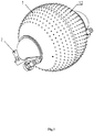
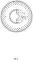
Fig. 1 is a structural perspective view of a preferred embodiment of the present invention; -
Fig. 2 is a perspective exploded view of the embodiment shown inFig. 1 ; -
Fig. 3 is a front view of the structure of the embodiment shown inFig. 1 ; -
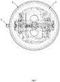
Fig. 4 is a structural side view of the embodiment shown inFig. 1 ; -
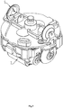
Fig. 5 is a structural perspective view of the rolling power unit of the embodiment shown inFig. 1 ; -
Fig. 6 is a front view of the structure of the rolling power unit of the embodiment shown inFig. 1 ; -
Fig. 7 is a structural side view of the rolling power unit in the embodiment shown inFig. 1 ; -
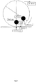
Fig. 8 is a schematic diagram of the motion of the rolling power unit in the embodiment shown inFig. 1 ; -
Fig. 9 is a top plan view of the structure of the steering unit in the embodiment shown inFig. 1 ; -
Fig. 10 is a front view of the structure of a propulsion unit according to another preferred embodiment of the present invention; -
Fig. 11 is a front view of the structure of the propulsion unit in the embodiment shown inFig. 10 ; - 1 outer spherical shell; 1.1 mounting part; 1.2 convex structure; 2 propulsion unit; 3 support frame; 4 inner spherical shell; 5 roller;6 steering gear; 7 drive motor; 8 center support; 9 elastic support; 10 spring; 11 steering gear.
- The invention will now be described further with reference to the accompanying drawings. The following examples are merely illustrative of the technical aspects of the present invention and are not intended to limit the scope of the invention.
- As shown in
Figs. 1 to 9 , a roll-over floating mixed multi-habitat submersible comprisesspherical shell 1, propulsion unit 2, innerspherical shell 4, rolling power unit, buoyant force adjusting unit and steering unit. In particular, in order to facilitate better contact and movement with the bottom of the water bodyor land, the outerspherical shell 1 is a spherical housing. Its inner and outer walls are spherical. The outer wall is distributed with a number of convex structure 1.2 or similar tires groove texture structure. - For better fixing of the inner
spherical shell 4 in the outerspherical shell 1 and for facilitating the better generation of the eccentric torque of rolling power unit, innerspherical shell 4 is also spherical shell and the inner and outer walls are spherical. The innerspherical shell 4 is set in the innerspherical shell 1 concentrically through a support frame 3 and is rotatable relative to the outerspherical shell 1 about the first shaft. Rolling power unit is set in the innerspherical shell 4, buoyancy adjusting unit and the steering unit are installed in the space between the outerspherical shell 1 and the innerspherical shell 4. - Theeccentric torque generated by rolling power unit is equipped with the structure: the rolling power unit comprising a turret, a
roller 5, adrive motor 7, a controller and a battery. Theroller 5 is mounted on the opposite sides of the turret, and theroller 5 is in rolling contact with the inner wall of the innerspherical shell 4 and thedrive motor 7 drives theroller 5 on one side thereof so that the turret can be rotated about the second axis of the innerspherical shell 4. The controller is electrically connected to thedrive motor 7 to control thedrive motor 7 to perform the forward / reverse control. The battery is connected respectively with the controller and thedrive motor 7 electrically to supply power thereto. Thedrive motor 7 and the battery are used as components of high quality in the rolling power unit and are thus eccentrically mounted on the turret as a weight so that the eccentric torque can be generated when the turret is rotated. - As shown in
Fig. 8 , the innerspherical shell 4 and the outerspherical shell 1 are regarded as a complete sphere and the actionpoint of the sphere and the surface supporting the sphere is the supporting point. Regard thedrive motor 7 and battery as inverted pendulum, under the action of gravity, in the sphere bottom. When thedrive motor 7 is operated to rotate the inverted pendulum relative to the sphere, the inverted weight forms a torque relative to the supporting point which drives the ball in the reverse direction and then pendulum returns to the initial position. During the rotation of the sphere, the friction supporting surface simultaneously drives the sphere forward. Repeat the process to continuously roll the sphere. - In order to enable the
roller 5 to always contact the inner wall of the innerspherical shell 4 during rotation, the turret is divided into two parts which are movable, one part is thecenter support 8 and the other part is the elastic support 9. The pair ofrollers 5 mounted oncenter support 8 are driven bydrive motor 7, respectively. - The elastic support 9 is elastically connected along the center line of both
sides roller 5 through thespring 10 andcenter support 8. Thespring 10 makes elastic support 9 have a tendency to move outwardly relative to thecenter support 8, so that both sides of theroller 5 are always movable against the inner wall of the innerspherical shell 4. - The buoyant adjustment unit that changes submersible position in the water has a structure: the buoyant adjustment comprises a dosing tank, a water pump and an integrated valve group. The water pump adopts a one-way pump, the water is sucked or discharged by the water pump and the valve group in the drain tank which is a tubular annular structure and is arranged around the outer circumference of the inner
spherical shell 4 so that the distribution of the weight of the water can have a uniform distribution of the weight to affect the eccentric torque. - When the one-way pump is turned on, the water is automatically sucked into the drain tank by means of the water pressure. The weight of the submersible increases and exceeds its buoyancy to sink to the bottom of the water body. At this time, the movement at the bottom of the water body is achieved by rolling the power unit. After a portion of the water is discharged from the drain tank, the weight of the submersible falls and is equal to its buoyancy so that the submersible floats in the water body, and the submersible movement is achieved by the propulsion device 2. One-way pump works reversely to further discharge the water and the weight of the submersible is less than its buoyancy and thus rise to the surface to achieve the recovery of the submersible.
- The steering unit that achieves the pivot steering is equipped with the structure: steering device comprises a
steering gear 6, a steering gear 11 and a steering motor. Thesteering gear 6 is provided on the outer wall of the innerspherical shell 4 with its axis of rotation collinear with the first axis, set along the equatorial line of the inner spherical shell. The steering motor is provided on the inner wall of the outerspherical shell 1 and the steering gear 11 is set on the rotating shaft of the steering motor and engaged with thesteering gear 6. - After the steering of the steering motor, the inner
spherical shell 4 and its inner rolling power unit can revolve to a certain angle relative to its original position, then the submersible will move along the new direction in the water bottom or on the land. - The propulsion unit 2 is installed in a symmetrical manner and the outer
spherical shell 1 has, at its both ends, in its diameter direction, the mounting portion 1.1 protruding its outer wall. The propulsion unit 2 is provided on each mounting portion 1.1. The present invention has two types of propulsion unit 2, in particular:
The number of the propulsion unit 2 on each of the mounting portion 1.1 is two, and the two propulsion units 2 on the same mounting portion 1.1 are opposed to each other at an angle of 90 °. This installation ensures that the submersible provides a progressive, floating and three-degree-of-freedom thrust when rolling at any angle to achieve an emergency float. - As shown in
Figs. 10 and11 , the difference from the first embodiment is that in the present embodiment, the number of the propulsion unit is 2 and the propulsion unit 2 is ±90° rotatably provided on the mounting portion 1.1. Under normal situation, the two-side propulsion unit 2 is arranged horizontally to generate a forward drive thrust. In addition, the propulsion unit 2 can be further rotated to a vertical state to produce a floating, dive thrust. The mounting portion has a streamlined structure and is made of a transparent material to facilitate observation of the internal structure of the submersible. - It differs from
Embodiment 1 in that in the present embodiment, the water pump uses a bidirectional pump to effect water intake and drainage. - In order to prevent the nozzle of the manifold from being clogged by the sludge, a nozzle can be provided on the mounting portion so as to reduce the contact of the nozzle with the bottom or land of the water body.
- Whichever type of installation is used, the propulsion unit 2 will interfere with the movement of the divergent submersible. Therefore, the steering angle of the steering device may be set within the set range depending on the circumstances so as to avoid the interference effect of the propulsion unit 2 on the roll. In the present invention, the first axis is the Y-axis direction in
Fig. 2 , the second axis is the X-axis direction inFig. 2 , and the X-axis and the Y-axis are perpendicular to each other. - The submersible can be laid by the mother ship, or even rolled from the shore into the water or release from the air. With the action of its buoyant adjustment unit, it sinks into the bottom of the water body for rolling or floating movement. After the task is completed, it can roll back to mother ship from the bottom of water, which subverts the current traditional way of laying and recovering by using the deck to lay down. It plays an important role in offshore surveys, underwater observation, marine pasture monitoring, seabed long-term guarding and so on.
- The foregoing is merely a preferred embodiment of the present invention and it should be noted that it will be apparent to those skilled in the art that various modifications and variations can be made without departing from the technical principles of the invention. These modification and variation should also be regarded as the scope of protection of the present invention.
Claims (10)
- A roll-over floating mixed multi-habitat submersible based on built-in driving principle comprises an outer spherical shell (1), a propulsion unit (2), an inner spherical shell (4), a rolling power unit, a buoyancy adjusting unit and a driving steering unit;
the said outer spherical shell (1) has a spherical outer wall and the said inner spherical shell (4) has a spherical inner wall; the said inner spherical shell (4) is set in the said outer spherical shell (1), capable of rotating around a first axis direction relative to the said outer spherical shell (1); the said rolling power unit is set in the said inner spherical shell (4), capable of rotating around a second axis to generate an eccentric moment to advance or retract the submersible; the said buoyancy adjusting unit and the said steering unit are installed in the space between the said outer spherical shell (1) and the inner spherical shell (4), wherein the said buoyancy adjusting unit is capable of causing the submersible to sink or float in the water body, and the said steering unit is capable of driving the inner spherical shell (4) to rotate relative to the outer spherical shell (1); the said first axis is perpendicular to the said second axis. - The said roll-over floating mixed multi-habitat submersible based on built-in driving principle according to claim 1 is characterized as: the rolling power unit comprising a turret, rollers (5), a drive motor (7), a controller and a battery pack; the said rollers (5) being respectively mounted on opposite sides of the said turret, the said rollers (5) being in rolling contact with the said spherical inner wall, the said drive motor (7) driving one of the rollers (5) so that the said turret is movable relative to the said inner spherical shell (4); the said controller being electrically connected to the said drive motor (7), the said battery being electrically connected to the said controller and the said drive motor (7), respectively;
wherein, the said drive motor (7) and the battery are eccentrically mounted on the turret so that the rolling power unit generates an eccentric moment. - The said roll-over floating mixed multi-habitat submersible based on built-in driving principle according to claim 2 is characterized as: the said turret comprising: a central support and a resilient support; the said rollers (5) being mounted on the said central support and the resilient support; the said resilient support is resiliently connected to the said central support by means of a spring (10) in the direction of the center line of both sides of the roller (5) so that the both side rollers (5) are always in contact with the spherical inner wall.
- The said roll-over floating mixed multi-habitat submersible according to claim 1 is characterized as: the buoyancy adjusting unit comprising a drain tank, a water pump and an integrated valve group; the water being drawn into or being discharged in the said injection and drainage tank through the said water pump and the said valve group.
- The said roll-over floating mixed multi-habitat submersible based on built-in driving principle according to claim 4 is characterized as: the said drain tank being in the form of a tubular annular structure set up in a circumference of the said inner spherical shell (4).
- The said roll-over floating mixed multi-habitat submersible based on built-in driving principle according to claim 1 is characterized as: the said steering means comprising a steering gear ring, a steering gear and a steering motor; the said steering gear ring being set on the outer wall of the said inner spherical shell (4), the said steering motor being provided on the inner wall of the outer spherical shell (1), and the said steering gear being provided on the rotating shaft of the said steering motor and meshing with the steering gear ring.
- The said roll-over floating mixed multi-habitat submersible based on built-in driving principle according to claim 1 is characterized as: the said outer spherical shell (1) having a mounting portion for projecting an outer wall thereof at both ends in its diameter direction, and pushing units being respectively provided on each of the mounting portions.
- The said roll-over floating mixed multi-habitat submersible based on built-in driving principle according to claim 7 is characterized as: the number of propulsion units (2) on each mounting portion being two which are arranged symmetrically with vertical line at an angle of 90 °.
- The said roll-over floating mixed multi-habitat submersible based on built-in driving principle according to claim 7 is characterized as: the number of propulsion units (2) on each mounting portion being one which is capable of ±90° rotatably provided on the mounting portion.
- The said roll-over floating mixed multi-habitat submersible based on built-in driving principle according to anyone of claims 1-9 is characterized as: the said outer wall of said outer spherical shell (1) being distributed with a plurality of convex structures or groove texture structure to increase underwater friction.
Applications Claiming Priority (2)
| Application Number | Priority Date | Filing Date | Title |
|---|---|---|---|
| CN201710037213.5A CN106828831B (en) | 2017-01-19 | 2017-01-19 | A kind of rolling into based on built-in driving principle is swum hybrid submersible of dwelling more |
| PCT/CN2017/088401 WO2018133314A1 (en) | 2017-01-19 | 2017-06-15 | Rolling and floating combined amphibious vehicle based on internal drive principle |
Publications (3)
| Publication Number | Publication Date |
|---|---|
| EP3372486A1 EP3372486A1 (en) | 2018-09-12 |
| EP3372486A4 EP3372486A4 (en) | 2019-01-23 |
| EP3372486B1 true EP3372486B1 (en) | 2019-09-18 |
Family
ID=59123299
Family Applications (1)
| Application Number | Title | Priority Date | Filing Date |
|---|---|---|---|
| EP17804788.2A Active EP3372486B1 (en) | 2017-01-19 | 2017-06-15 | Rolling and floating combined amphibious vehicle based on internal drive principle |
Country Status (5)
| Country | Link |
|---|---|
| US (1) | US20180370605A1 (en) |
| EP (1) | EP3372486B1 (en) |
| JP (1) | JP6484387B2 (en) |
| CN (1) | CN106828831B (en) |
| WO (1) | WO2018133314A1 (en) |
Families Citing this family (23)
| Publication number | Priority date | Publication date | Assignee | Title |
|---|---|---|---|---|
| CN106828831B (en) * | 2017-01-19 | 2018-01-16 | 河海大学 | A kind of rolling into based on built-in driving principle is swum hybrid submersible of dwelling more |
| CN108622346A (en) * | 2017-07-31 | 2018-10-09 | 乐清市华尊电气有限公司 | A kind of spherical underwater robots that driving direction can be adjusted in ring is 360 degree all |
| CN108820168A (en) * | 2017-07-31 | 2018-11-16 | 李学忠 | The underwater robot that can be driven with any angle |
| CN107719609B (en) * | 2017-10-13 | 2019-07-12 | 河海大学 | A spherical submersible for emergency self-rescue |
| CN108163165B (en) * | 2017-12-23 | 2020-09-01 | 左立亮 | Rotary body diving equipment |
| CN109367681A (en) * | 2018-10-17 | 2019-02-22 | 河海大学 | A spherical device for floating and rolling into benthic submersible |
| CN110667807B (en) * | 2019-10-16 | 2021-04-09 | 河海大学 | Improved spherical roll-in underwater robot |
| CN110844032B (en) * | 2019-11-19 | 2023-10-27 | 贵州电网有限责任公司 | Spherical water sports device with adjustable center of gravity of floating center |
| CN110843439B (en) * | 2019-11-28 | 2023-04-28 | 北京邮电大学 | Amphibious double-ball robot |
| CN112156204A (en) * | 2020-09-23 | 2021-01-01 | 安徽惠丰国药有限公司 | Multistage all-round sterilizing equipment for traditional chinese medicine preparation process |
| CN114590375B (en) * | 2020-12-07 | 2023-04-28 | 中国科学院沈阳自动化研究所 | Wheel type walking and floating double-mode underwater robot under ice |
| CN112895825B (en) * | 2021-03-17 | 2022-04-08 | 哈尔滨工程大学 | A variable-configuration multimodal amphibious joint |
| CN113479307B (en) * | 2021-08-11 | 2022-11-18 | 刘满贤 | Outdoor automatic mapping device |
| CN113844626B (en) * | 2021-09-01 | 2024-04-26 | 哈尔滨工业大学 | A sandwich-structured multi-degree-of-freedom deep-sea vehicle based on piezoelectric drive |
| CN114044114B (en) * | 2021-10-18 | 2024-05-28 | 中国舰船研究设计中心 | Submersible spherical cabin rotation support assembly |
| CN114194366B (en) * | 2021-12-17 | 2023-01-03 | 中国地质大学(武汉) | Underwater self-balancing commercial aircraft and shell structure thereof |
| CN114285491B (en) * | 2021-12-18 | 2023-08-01 | 北京东迅通科技有限公司 | A multi-terminal adjustable underwater optical communication networking system |
| CN115246468B (en) * | 2022-07-20 | 2023-06-20 | 广东工业大学 | Bionic jellyfish robot and control method thereof |
| CN116424040B (en) * | 2023-03-30 | 2024-01-26 | 湖北工业大学 | Amphibious exploration robot with water wheels |
| CN116811495A (en) * | 2023-06-02 | 2023-09-29 | 南京理工大学 | Amphibious spherical robot propelled by composite vectors and control method thereof |
| CN117863784B (en) * | 2024-03-13 | 2024-06-25 | 北京晶品特装科技股份有限公司 | Automatic detection device and method based on mobile robot |
| CN118439132B (en) * | 2024-07-08 | 2024-09-13 | 山东华地测绘地理信息有限公司 | Marine engineering survey and drawing water distance survey appearance |
| CN119190273B (en) * | 2024-11-28 | 2025-02-18 | 山东省蓝睿科技开发有限公司 | A buoy system and networking deployment method based on multi-source information fusion |
Family Cites Families (21)
| Publication number | Priority date | Publication date | Assignee | Title |
|---|---|---|---|---|
| US4992999A (en) * | 1966-07-28 | 1991-02-12 | The United States Of America As Represented By The Secretary Of The Navy | Submarine drone for carrying a barrel stave-type transducer array |
| US4377982A (en) * | 1978-03-06 | 1983-03-29 | The Bendix Corporation | Spherical vehicle for operation in a fluid medium |
| US4455962A (en) * | 1978-03-06 | 1984-06-26 | The Bendix Corporation | Spherical underwater vehicle |
| US4501569A (en) * | 1983-01-25 | 1985-02-26 | Clark Jr Leonard R | Spherical vehicle control system |
| US4571192A (en) * | 1983-11-09 | 1986-02-18 | Allied Corporation | Self propelled spherical vehicle |
| CN1565875A (en) * | 2003-06-26 | 2005-01-19 | 杨晶明 | Ball-shaped vehicle |
| US8220408B2 (en) * | 2007-07-31 | 2012-07-17 | Stone William C | Underwater vehicle with sonar array |
| CN101279619A (en) * | 2008-04-21 | 2008-10-08 | 战强 | High mobility spherical detecting robot |
| CN101318549B (en) * | 2008-05-22 | 2010-04-14 | 北京邮电大学 | An amphibious spherical robot |
| CN101565095B (en) * | 2009-05-22 | 2011-04-06 | 北京邮电大学 | Underwater spherical robot with six degrees of freedom |
| US8297214B2 (en) * | 2010-08-31 | 2012-10-30 | Lotz Jeffrey Paul | Remotely operated submersible vehicle |
| DE102010053443B4 (en) * | 2010-12-06 | 2016-03-31 | Deutsches Zentrum für Luft- und Raumfahrt e.V. | Mobile robot with external rolling surface and gyroscope device and method for operating such |
| CN103129337A (en) * | 2013-01-05 | 2013-06-05 | 朱志强 | Amphibious rolling cabin with built-in drive |
| US9428019B1 (en) * | 2013-07-09 | 2016-08-30 | Guardbot Inc. | Drive and stabilizaton system for amphibious robotic ball |
| CN103358839B (en) * | 2013-08-05 | 2015-09-02 | 战强 | A kind of Amphibious spherical scout robot |
| CN203698464U (en) * | 2014-01-22 | 2014-07-09 | 中国人民解放军国防科学技术大学 | Ball-like type detection robot with characteristic of tumbler |
| USD742801S1 (en) * | 2014-11-07 | 2015-11-10 | Abb Technology Ag | Grid-style hull |
| US9926052B2 (en) * | 2015-12-30 | 2018-03-27 | Abb Schweiz Ag | Control mechanism for transformer in-situ inspection device |
| CN205439857U (en) * | 2016-04-05 | 2016-08-10 | 许祖勇 | Spherical land, water and air no. 3 intelligent scout robot of dwelling |
| CN206466144U (en) * | 2017-01-19 | 2017-09-05 | 河海大学 | A kind of rolling into based on built-in driving principle is swum hybrid submersible of dwelling more |
| CN106828831B (en) * | 2017-01-19 | 2018-01-16 | 河海大学 | A kind of rolling into based on built-in driving principle is swum hybrid submersible of dwelling more |
-
2017
- 2017-01-19 CN CN201710037213.5A patent/CN106828831B/en active Active
- 2017-06-15 WO PCT/CN2017/088401 patent/WO2018133314A1/en not_active Ceased
- 2017-06-15 EP EP17804788.2A patent/EP3372486B1/en active Active
- 2017-06-15 US US15/579,890 patent/US20180370605A1/en not_active Abandoned
- 2017-06-15 JP JP2018502251A patent/JP6484387B2/en not_active Expired - Fee Related
Non-Patent Citations (1)
| Title |
|---|
| None * |
Also Published As
| Publication number | Publication date |
|---|---|
| JP2019506321A (en) | 2019-03-07 |
| EP3372486A1 (en) | 2018-09-12 |
| WO2018133314A1 (en) | 2018-07-26 |
| JP6484387B2 (en) | 2019-03-13 |
| EP3372486A4 (en) | 2019-01-23 |
| CN106828831A (en) | 2017-06-13 |
| CN106828831B (en) | 2018-01-16 |
| US20180370605A1 (en) | 2018-12-27 |
Similar Documents
| Publication | Publication Date | Title |
|---|---|---|
| EP3372486A1 (en) | Rolling and floating combined amphibious vehicle based on internal drive principle | |
| CN109703705B (en) | A semi-submersible unmanned platform | |
| CN201511768U (en) | An amphibious robot driven by integrated wheels, paddles and legs | |
| US7730978B2 (en) | All-terrain robotic omni-directional drive assembly | |
| CN107512380B (en) | An omnidirectional propeller, ship and floating platform | |
| AU2016301238B2 (en) | Water drone | |
| CN102050162B (en) | Amphibious robot with integrally-driven wheel paddle legs | |
| CN102059927B (en) | Paddle-pedal plate hybrid driving-based amphibious robot | |
| JP2009143331A (en) | Tsunami and wave observation buoy | |
| CN102887216B (en) | Underwater variant glider | |
| CN106043634A (en) | High-maneuverability underwater glider | |
| CN113090436A (en) | Ocean energy self-adaptive water flow direction power generation device | |
| CN119239886A (en) | An underwater robot with adjustable posture based on buoyancy adjustment system | |
| CN205632940U (en) | Unmanned ship of hydrofoil of little water plane of stealthy monomer | |
| CN110422307B (en) | Control method of deep sea multi-joint submersible vehicle | |
| CN116252935A (en) | Bionic machine penguin | |
| CN203996828U (en) | A kind of self-balancing ship | |
| CN115520362A (en) | A bionic flat submersible and its operation method | |
| CN115493025A (en) | A water pipe detection robot | |
| CN206466144U (en) | A kind of rolling into based on built-in driving principle is swum hybrid submersible of dwelling more | |
| CN205499301U (en) | Solar energy measuring platform that glides under water | |
| CN112606976A (en) | Submersible wave glider | |
| CN208149580U (en) | A vector propulsion quadrotor underwater vehicle | |
| CN103963775A (en) | Intertidal zone self-elevating air hover-working platform | |
| RU127362U1 (en) | OUTBOAT BOAT MOTOR |
Legal Events
| Date | Code | Title | Description |
|---|---|---|---|
| STAA | Information on the status of an ep patent application or granted ep patent |
Free format text: STATUS: UNKNOWN |
|
| STAA | Information on the status of an ep patent application or granted ep patent |
Free format text: STATUS: THE INTERNATIONAL PUBLICATION HAS BEEN MADE |
|
| PUAI | Public reference made under article 153(3) epc to a published international application that has entered the european phase |
Free format text: ORIGINAL CODE: 0009012 |
|
| STAA | Information on the status of an ep patent application or granted ep patent |
Free format text: STATUS: REQUEST FOR EXAMINATION WAS MADE |
|
| 17P | Request for examination filed |
Effective date: 20171207 |
|
| AK | Designated contracting states |
Kind code of ref document: A1 Designated state(s): AL AT BE BG CH CY CZ DE DK EE ES FI FR GB GR HR HU IE IS IT LI LT LU LV MC MK MT NL NO PL PT RO RS SE SI SK SM TR |
|
| AX | Request for extension of the european patent |
Extension state: BA ME |
|
| R17P | Request for examination filed (corrected) |
Effective date: 20171207 |
|
| A4 | Supplementary search report drawn up and despatched |
Effective date: 20181220 |
|
| RIC1 | Information provided on ipc code assigned before grant |
Ipc: B60F 3/00 20060101ALI20181214BHEP Ipc: B63G 8/16 20060101ALI20181214BHEP Ipc: B63C 11/52 20060101AFI20181214BHEP Ipc: B63G 8/22 20060101ALI20181214BHEP |
|
| GRAP | Despatch of communication of intention to grant a patent |
Free format text: ORIGINAL CODE: EPIDOSNIGR1 |
|
| STAA | Information on the status of an ep patent application or granted ep patent |
Free format text: STATUS: GRANT OF PATENT IS INTENDED |
|
| INTG | Intention to grant announced |
Effective date: 20190503 |
|
| GRAS | Grant fee paid |
Free format text: ORIGINAL CODE: EPIDOSNIGR3 |
|
| GRAA | (expected) grant |
Free format text: ORIGINAL CODE: 0009210 |
|
| STAA | Information on the status of an ep patent application or granted ep patent |
Free format text: STATUS: THE PATENT HAS BEEN GRANTED |
|
| AK | Designated contracting states |
Kind code of ref document: B1 Designated state(s): AL AT BE BG CH CY CZ DE DK EE ES FI FR GB GR HR HU IE IS IT LI LT LU LV MC MK MT NL NO PL PT RO RS SE SI SK SM TR |
|
| DAV | Request for validation of the european patent (deleted) | ||
| DAX | Request for extension of the european patent (deleted) | ||
| REG | Reference to a national code |
Ref country code: GB Ref legal event code: FG4D |
|
| REG | Reference to a national code |
Ref country code: CH Ref legal event code: EP |
|
| REG | Reference to a national code |
Ref country code: DE Ref legal event code: R096 Ref document number: 602017007200 Country of ref document: DE |
|
| REG | Reference to a national code |
Ref country code: AT Ref legal event code: REF Ref document number: 1180979 Country of ref document: AT Kind code of ref document: T Effective date: 20191015 |
|
| REG | Reference to a national code |
Ref country code: IE Ref legal event code: FG4D |
|
| REG | Reference to a national code |
Ref country code: NL Ref legal event code: MP Effective date: 20190918 |
|
| PG25 | Lapsed in a contracting state [announced via postgrant information from national office to epo] |
Ref country code: HR Free format text: LAPSE BECAUSE OF FAILURE TO SUBMIT A TRANSLATION OF THE DESCRIPTION OR TO PAY THE FEE WITHIN THE PRESCRIBED TIME-LIMIT Effective date: 20190918 Ref country code: SE Free format text: LAPSE BECAUSE OF FAILURE TO SUBMIT A TRANSLATION OF THE DESCRIPTION OR TO PAY THE FEE WITHIN THE PRESCRIBED TIME-LIMIT Effective date: 20190918 Ref country code: BG Free format text: LAPSE BECAUSE OF FAILURE TO SUBMIT A TRANSLATION OF THE DESCRIPTION OR TO PAY THE FEE WITHIN THE PRESCRIBED TIME-LIMIT Effective date: 20191218 Ref country code: LT Free format text: LAPSE BECAUSE OF FAILURE TO SUBMIT A TRANSLATION OF THE DESCRIPTION OR TO PAY THE FEE WITHIN THE PRESCRIBED TIME-LIMIT Effective date: 20190918 Ref country code: FI Free format text: LAPSE BECAUSE OF FAILURE TO SUBMIT A TRANSLATION OF THE DESCRIPTION OR TO PAY THE FEE WITHIN THE PRESCRIBED TIME-LIMIT Effective date: 20190918 Ref country code: NO Free format text: LAPSE BECAUSE OF FAILURE TO SUBMIT A TRANSLATION OF THE DESCRIPTION OR TO PAY THE FEE WITHIN THE PRESCRIBED TIME-LIMIT Effective date: 20191218 |
|
| REG | Reference to a national code |
Ref country code: LT Ref legal event code: MG4D |
|
| PG25 | Lapsed in a contracting state [announced via postgrant information from national office to epo] |
Ref country code: RS Free format text: LAPSE BECAUSE OF FAILURE TO SUBMIT A TRANSLATION OF THE DESCRIPTION OR TO PAY THE FEE WITHIN THE PRESCRIBED TIME-LIMIT Effective date: 20190918 Ref country code: GR Free format text: LAPSE BECAUSE OF FAILURE TO SUBMIT A TRANSLATION OF THE DESCRIPTION OR TO PAY THE FEE WITHIN THE PRESCRIBED TIME-LIMIT Effective date: 20191219 Ref country code: LV Free format text: LAPSE BECAUSE OF FAILURE TO SUBMIT A TRANSLATION OF THE DESCRIPTION OR TO PAY THE FEE WITHIN THE PRESCRIBED TIME-LIMIT Effective date: 20190918 Ref country code: AL Free format text: LAPSE BECAUSE OF FAILURE TO SUBMIT A TRANSLATION OF THE DESCRIPTION OR TO PAY THE FEE WITHIN THE PRESCRIBED TIME-LIMIT Effective date: 20190918 |
|
| REG | Reference to a national code |
Ref country code: AT Ref legal event code: MK05 Ref document number: 1180979 Country of ref document: AT Kind code of ref document: T Effective date: 20190918 |
|
| PG25 | Lapsed in a contracting state [announced via postgrant information from national office to epo] |
Ref country code: ES Free format text: LAPSE BECAUSE OF FAILURE TO SUBMIT A TRANSLATION OF THE DESCRIPTION OR TO PAY THE FEE WITHIN THE PRESCRIBED TIME-LIMIT Effective date: 20190918 Ref country code: PT Free format text: LAPSE BECAUSE OF FAILURE TO SUBMIT A TRANSLATION OF THE DESCRIPTION OR TO PAY THE FEE WITHIN THE PRESCRIBED TIME-LIMIT Effective date: 20200120 Ref country code: NL Free format text: LAPSE BECAUSE OF FAILURE TO SUBMIT A TRANSLATION OF THE DESCRIPTION OR TO PAY THE FEE WITHIN THE PRESCRIBED TIME-LIMIT Effective date: 20190918 Ref country code: EE Free format text: LAPSE BECAUSE OF FAILURE TO SUBMIT A TRANSLATION OF THE DESCRIPTION OR TO PAY THE FEE WITHIN THE PRESCRIBED TIME-LIMIT Effective date: 20190918 Ref country code: AT Free format text: LAPSE BECAUSE OF FAILURE TO SUBMIT A TRANSLATION OF THE DESCRIPTION OR TO PAY THE FEE WITHIN THE PRESCRIBED TIME-LIMIT Effective date: 20190918 Ref country code: IT Free format text: LAPSE BECAUSE OF FAILURE TO SUBMIT A TRANSLATION OF THE DESCRIPTION OR TO PAY THE FEE WITHIN THE PRESCRIBED TIME-LIMIT Effective date: 20190918 Ref country code: RO Free format text: LAPSE BECAUSE OF FAILURE TO SUBMIT A TRANSLATION OF THE DESCRIPTION OR TO PAY THE FEE WITHIN THE PRESCRIBED TIME-LIMIT Effective date: 20190918 Ref country code: PL Free format text: LAPSE BECAUSE OF FAILURE TO SUBMIT A TRANSLATION OF THE DESCRIPTION OR TO PAY THE FEE WITHIN THE PRESCRIBED TIME-LIMIT Effective date: 20190918 |
|
| PG25 | Lapsed in a contracting state [announced via postgrant information from national office to epo] |
Ref country code: SM Free format text: LAPSE BECAUSE OF FAILURE TO SUBMIT A TRANSLATION OF THE DESCRIPTION OR TO PAY THE FEE WITHIN THE PRESCRIBED TIME-LIMIT Effective date: 20190918 Ref country code: IS Free format text: LAPSE BECAUSE OF FAILURE TO SUBMIT A TRANSLATION OF THE DESCRIPTION OR TO PAY THE FEE WITHIN THE PRESCRIBED TIME-LIMIT Effective date: 20200224 Ref country code: SK Free format text: LAPSE BECAUSE OF FAILURE TO SUBMIT A TRANSLATION OF THE DESCRIPTION OR TO PAY THE FEE WITHIN THE PRESCRIBED TIME-LIMIT Effective date: 20190918 Ref country code: CZ Free format text: LAPSE BECAUSE OF FAILURE TO SUBMIT A TRANSLATION OF THE DESCRIPTION OR TO PAY THE FEE WITHIN THE PRESCRIBED TIME-LIMIT Effective date: 20190918 |
|
| REG | Reference to a national code |
Ref country code: DE Ref legal event code: R097 Ref document number: 602017007200 Country of ref document: DE |
|
| PLBE | No opposition filed within time limit |
Free format text: ORIGINAL CODE: 0009261 |
|
| STAA | Information on the status of an ep patent application or granted ep patent |
Free format text: STATUS: NO OPPOSITION FILED WITHIN TIME LIMIT |
|
| PG2D | Information on lapse in contracting state deleted |
Ref country code: IS |
|
| PG25 | Lapsed in a contracting state [announced via postgrant information from national office to epo] |
Ref country code: DK Free format text: LAPSE BECAUSE OF FAILURE TO SUBMIT A TRANSLATION OF THE DESCRIPTION OR TO PAY THE FEE WITHIN THE PRESCRIBED TIME-LIMIT Effective date: 20190918 Ref country code: IS Free format text: LAPSE BECAUSE OF FAILURE TO SUBMIT A TRANSLATION OF THE DESCRIPTION OR TO PAY THE FEE WITHIN THE PRESCRIBED TIME-LIMIT Effective date: 20200119 |
|
| PGFP | Annual fee paid to national office [announced via postgrant information from national office to epo] |
Ref country code: DE Payment date: 20200612 Year of fee payment: 4 Ref country code: FR Payment date: 20200630 Year of fee payment: 4 |
|
| 26N | No opposition filed |
Effective date: 20200619 |
|
| PG25 | Lapsed in a contracting state [announced via postgrant information from national office to epo] |
Ref country code: SI Free format text: LAPSE BECAUSE OF FAILURE TO SUBMIT A TRANSLATION OF THE DESCRIPTION OR TO PAY THE FEE WITHIN THE PRESCRIBED TIME-LIMIT Effective date: 20190918 |
|
| PG25 | Lapsed in a contracting state [announced via postgrant information from national office to epo] |
Ref country code: MC Free format text: LAPSE BECAUSE OF FAILURE TO SUBMIT A TRANSLATION OF THE DESCRIPTION OR TO PAY THE FEE WITHIN THE PRESCRIBED TIME-LIMIT Effective date: 20190918 |
|
| REG | Reference to a national code |
Ref country code: CH Ref legal event code: PL |
|
| PG25 | Lapsed in a contracting state [announced via postgrant information from national office to epo] |
Ref country code: LU Free format text: LAPSE BECAUSE OF NON-PAYMENT OF DUE FEES Effective date: 20200615 |
|
| REG | Reference to a national code |
Ref country code: BE Ref legal event code: MM Effective date: 20200630 |
|
| PG25 | Lapsed in a contracting state [announced via postgrant information from national office to epo] |
Ref country code: LI Free format text: LAPSE BECAUSE OF NON-PAYMENT OF DUE FEES Effective date: 20200630 Ref country code: IE Free format text: LAPSE BECAUSE OF NON-PAYMENT OF DUE FEES Effective date: 20200615 Ref country code: CH Free format text: LAPSE BECAUSE OF NON-PAYMENT OF DUE FEES Effective date: 20200630 |
|
| PG25 | Lapsed in a contracting state [announced via postgrant information from national office to epo] |
Ref country code: BE Free format text: LAPSE BECAUSE OF NON-PAYMENT OF DUE FEES Effective date: 20200630 |
|
| REG | Reference to a national code |
Ref country code: DE Ref legal event code: R119 Ref document number: 602017007200 Country of ref document: DE |
|
| PG25 | Lapsed in a contracting state [announced via postgrant information from national office to epo] |
Ref country code: DE Free format text: LAPSE BECAUSE OF NON-PAYMENT OF DUE FEES Effective date: 20220101 |
|
| PG25 | Lapsed in a contracting state [announced via postgrant information from national office to epo] |
Ref country code: TR Free format text: LAPSE BECAUSE OF FAILURE TO SUBMIT A TRANSLATION OF THE DESCRIPTION OR TO PAY THE FEE WITHIN THE PRESCRIBED TIME-LIMIT Effective date: 20190918 Ref country code: MT Free format text: LAPSE BECAUSE OF FAILURE TO SUBMIT A TRANSLATION OF THE DESCRIPTION OR TO PAY THE FEE WITHIN THE PRESCRIBED TIME-LIMIT Effective date: 20190918 Ref country code: FR Free format text: LAPSE BECAUSE OF NON-PAYMENT OF DUE FEES Effective date: 20210630 Ref country code: CY Free format text: LAPSE BECAUSE OF FAILURE TO SUBMIT A TRANSLATION OF THE DESCRIPTION OR TO PAY THE FEE WITHIN THE PRESCRIBED TIME-LIMIT Effective date: 20190918 |
|
| PG25 | Lapsed in a contracting state [announced via postgrant information from national office to epo] |
Ref country code: MK Free format text: LAPSE BECAUSE OF FAILURE TO SUBMIT A TRANSLATION OF THE DESCRIPTION OR TO PAY THE FEE WITHIN THE PRESCRIBED TIME-LIMIT Effective date: 20190918 |
|
| PGFP | Annual fee paid to national office [announced via postgrant information from national office to epo] |
Ref country code: GB Payment date: 20250625 Year of fee payment: 9 |