EP3372007B1 - Zeitplanung von ues mit gemischter tti-länge - Google Patents
Zeitplanung von ues mit gemischter tti-länge Download PDFInfo
- Publication number
- EP3372007B1 EP3372007B1 EP16861670.4A EP16861670A EP3372007B1 EP 3372007 B1 EP3372007 B1 EP 3372007B1 EP 16861670 A EP16861670 A EP 16861670A EP 3372007 B1 EP3372007 B1 EP 3372007B1
- Authority
- EP
- European Patent Office
- Prior art keywords
- user equipment
- time interval
- transmission time
- scheduled
- tti
- Prior art date
- Legal status (The legal status is an assumption and is not a legal conclusion. Google has not performed a legal analysis and makes no representation as to the accuracy of the status listed.)
- Active
Links
Images

Classifications
-
- H—ELECTRICITY
- H04—ELECTRIC COMMUNICATION TECHNIQUE
- H04L—TRANSMISSION OF DIGITAL INFORMATION, e.g. TELEGRAPHIC COMMUNICATION
- H04L5/00—Arrangements affording multiple use of the transmission path
- H04L5/14—Two-way operation using the same type of signal, i.e. duplex
-
- H—ELECTRICITY
- H04—ELECTRIC COMMUNICATION TECHNIQUE
- H04W—WIRELESS COMMUNICATION NETWORKS
- H04W72/00—Local resource management
- H04W72/50—Allocation or scheduling criteria for wireless resources
- H04W72/52—Allocation or scheduling criteria for wireless resources based on load
-
- H—ELECTRICITY
- H04—ELECTRIC COMMUNICATION TECHNIQUE
- H04L—TRANSMISSION OF DIGITAL INFORMATION, e.g. TELEGRAPHIC COMMUNICATION
- H04L1/00—Arrangements for detecting or preventing errors in the information received
- H04L1/0001—Systems modifying transmission characteristics according to link quality, e.g. power backoff
- H04L1/0006—Systems modifying transmission characteristics according to link quality, e.g. power backoff by adapting the transmission format
- H04L1/0007—Systems modifying transmission characteristics according to link quality, e.g. power backoff by adapting the transmission format by modifying the frame length
-
- H—ELECTRICITY
- H04—ELECTRIC COMMUNICATION TECHNIQUE
- H04L—TRANSMISSION OF DIGITAL INFORMATION, e.g. TELEGRAPHIC COMMUNICATION
- H04L1/00—Arrangements for detecting or preventing errors in the information received
- H04L1/0001—Systems modifying transmission characteristics according to link quality, e.g. power backoff
- H04L1/0015—Systems modifying transmission characteristics according to link quality, e.g. power backoff characterised by the adaptation strategy
- H04L1/0017—Systems modifying transmission characteristics according to link quality, e.g. power backoff characterised by the adaptation strategy where the mode-switching is based on Quality of Service requirement
- H04L1/0018—Systems modifying transmission characteristics according to link quality, e.g. power backoff characterised by the adaptation strategy where the mode-switching is based on Quality of Service requirement based on latency requirement
-
- H—ELECTRICITY
- H04—ELECTRIC COMMUNICATION TECHNIQUE
- H04L—TRANSMISSION OF DIGITAL INFORMATION, e.g. TELEGRAPHIC COMMUNICATION
- H04L25/00—Baseband systems
-
- H—ELECTRICITY
- H04—ELECTRIC COMMUNICATION TECHNIQUE
- H04L—TRANSMISSION OF DIGITAL INFORMATION, e.g. TELEGRAPHIC COMMUNICATION
- H04L5/00—Arrangements affording multiple use of the transmission path
- H04L5/0001—Arrangements for dividing the transmission path
- H04L5/0014—Three-dimensional division
- H04L5/0023—Time-frequency-space
-
- H—ELECTRICITY
- H04—ELECTRIC COMMUNICATION TECHNIQUE
- H04L—TRANSMISSION OF DIGITAL INFORMATION, e.g. TELEGRAPHIC COMMUNICATION
- H04L5/00—Arrangements affording multiple use of the transmission path
- H04L5/003—Arrangements for allocating sub-channels of the transmission path
- H04L5/0078—Timing of allocation
- H04L5/0082—Timing of allocation at predetermined intervals
-
- H—ELECTRICITY
- H04—ELECTRIC COMMUNICATION TECHNIQUE
- H04L—TRANSMISSION OF DIGITAL INFORMATION, e.g. TELEGRAPHIC COMMUNICATION
- H04L5/00—Arrangements affording multiple use of the transmission path
- H04L5/0091—Signalling for the administration of the divided path, e.g. signalling of configuration information
- H04L5/0094—Indication of how sub-channels of the path are allocated
-
- H—ELECTRICITY
- H04—ELECTRIC COMMUNICATION TECHNIQUE
- H04W—WIRELESS COMMUNICATION NETWORKS
- H04W28/00—Network traffic management; Network resource management
- H04W28/02—Traffic management, e.g. flow control or congestion control
- H04W28/06—Optimizing the usage of the radio link, e.g. header compression, information sizing, discarding information
-
- H—ELECTRICITY
- H04—ELECTRIC COMMUNICATION TECHNIQUE
- H04W—WIRELESS COMMUNICATION NETWORKS
- H04W72/00—Local resource management
- H04W72/04—Wireless resource allocation
- H04W72/044—Wireless resource allocation based on the type of the allocated resource
- H04W72/0446—Resources in time domain, e.g. slots or frames
-
- H—ELECTRICITY
- H04—ELECTRIC COMMUNICATION TECHNIQUE
- H04W—WIRELESS COMMUNICATION NETWORKS
- H04W72/00—Local resource management
- H04W72/12—Wireless traffic scheduling
- H04W72/121—Wireless traffic scheduling for groups of terminals or users
-
- H—ELECTRICITY
- H04—ELECTRIC COMMUNICATION TECHNIQUE
- H04W—WIRELESS COMMUNICATION NETWORKS
- H04W72/00—Local resource management
- H04W72/12—Wireless traffic scheduling
- H04W72/1263—Mapping of traffic onto schedule, e.g. scheduled allocation or multiplexing of flows
- H04W72/1273—Mapping of traffic onto schedule, e.g. scheduled allocation or multiplexing of flows of downlink data flows
-
- H—ELECTRICITY
- H04—ELECTRIC COMMUNICATION TECHNIQUE
- H04W—WIRELESS COMMUNICATION NETWORKS
- H04W72/00—Local resource management
- H04W72/20—Control channels or signalling for resource management
- H04W72/23—Control channels or signalling for resource management in the downlink direction of a wireless link, i.e. towards a terminal
-
- H—ELECTRICITY
- H04—ELECTRIC COMMUNICATION TECHNIQUE
- H04L—TRANSMISSION OF DIGITAL INFORMATION, e.g. TELEGRAPHIC COMMUNICATION
- H04L47/00—Traffic control in data switching networks
- H04L47/10—Flow control; Congestion control
- H04L47/27—Evaluation or update of window size, e.g. using information derived from acknowledged [ACK] packets
-
- H—ELECTRICITY
- H04—ELECTRIC COMMUNICATION TECHNIQUE
- H04W—WIRELESS COMMUNICATION NETWORKS
- H04W68/00—User notification, e.g. alerting and paging, for incoming communication, change of service or the like
- H04W68/02—Arrangements for increasing efficiency of notification or paging channel
Definitions
- This invention relates generally to scheduling user equipment (UEs) (e.g., wireless, portable devices) and, more specifically, relates to scheduling UEs with mixed TTI length.
- UEs user equipment
- This invention relates generally to scheduling user equipment (UEs) (e.g., wireless, portable devices) and, more specifically, relates to scheduling UEs with mixed TTI length.
- a TCP sender always maintains a window (called a congestion window) such that a number of packets in transit does not exceed the receiver's ability to receive the packets.
- TCP flow control has two stages: one is a slow start stage (also referred to as the exponential growth stage) and the second is the congestion avoidance stage (also referred to as the linear stage).
- a TCP connection starts with a slow start period during which the congestion window size is effectively doubled with each TCP acknowledgement received.
- the size of the window is increased until the size reaches a threshold (called a slow start threshold) or until a packet is lost. After reaching the threshold, the window size is increased linearly with each TCP acknowledgement received.
- 3GPP TSG RAN has agreed to a new Study Item to investigate new techniques to reduce the latency. See, e.g., Ericsson, Huawei, "New SI proposal: Study on Latency reduction techniques for LTE", RP-150465, 3GPP TSG RAN Meeting #67, Shanghai, China, March. 9 - 12, 2015 .
- This latency issue may be further exacerbated by using multiple TTI lengths, and it would be beneficial to address this and other issues.
- WO2015/096821A1 describes mechanisms that allow adaptive transmission time interval (TTI) coexistence in Long Term Evolution (LTE) and fifth generation (5G) cellular systems.
- TTI transmission time interval
- LTE Long Term Evolution
- 5G fifth generation
- WO2014/189429A1 describes techniques for managing transmission time interval switching in a wireless communication system.
- the invention relates to a user equipment, a method and a computer program product as set forth in the claims.
- the exemplary embodiments herein describe techniques for scheduling UEs with mixed TTI length. Additional description of these techniques is presented after a system into which the exemplary embodiments may be used is described.
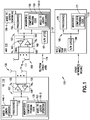
- FIG. 1 this figure shows a block diagram of one possible and non-limiting exemplary system in which the exemplary embodiments may be practiced.
- a user equipment (UE) 110 is in wireless communication with a wireless network 100.
- a UE is a wireless, typically mobile device that can access a wireless network.
- the UE 110 includes one or more processors 120, one or more memories 125, and one or more transceivers 130 interconnected through one or more buses 127.
- Each of the one or more transceivers 130 includes a receiver, Rx, 132 and a transmitter, Tx, 133.
- the one or more buses 127 may be address, data, or control buses, and may include any interconnection mechanism, such as a series of lines on a motherboard or integrated circuit, fiber optics or other optical communication equipment, and the like.
- the one or more transceivers 130 are connected to one or more antennas 128.
- the one or more memories 125 include computer program code 123.
- the UE 110 includes a mixed TTI length operation module 140, comprising one of or both parts 140-1 and/or 140-2, which may be implemented in a number of ways.
- the mixed TTI length operation module 140 may be implemented in hardware as mixed TTI length scheduling module 140-1, such as being implemented as part of the one or more processors 120.
- the mixed TTI length operation module 140-1 may be implemented also as an integrated circuit or through other hardware such as a programmable gate array.
- the mixed TTI length operation module 140 may be implemented as mixed TTI length scheduling module 140-2, which is implemented as computer program code 123 and is executed by the one or more processors 120.
- the one or more memories 125 and the computer program code 123 may be configured to, with the one or more processors 120, cause the user equipment 110 to perform one or more of the operations as described herein.
- the UE 110 communicates with eNB 170 via a wireless link 111.
- the eNB (evolved NodeB) 170 is a base station (e.g., for LTE, long term evolution) that provides access by wireless devices such as the UE 110 to the wireless network 100.
- the eNB 170 includes one or more processors 152, one or more memories 155, one or more network interfaces (N/W I/F(s)) 161, and one or more transceivers 160 interconnected through one or more buses 157.
- Each of the one or more transceivers 160 includes a receiver, Rx, 162 and a transmitter, Tx, 163.
- the one or more transceivers 160 are connected to one or more antennas 158.
- the one or more memories 155 include computer program code 153.
- the eNB 170 includes a mixed TTI length scheduling module 150, comprising one of or both parts 150-1 and/or 150-2, which may be implemented in a number of ways.
- the mixed TTI length scheduling module 150 may be implemented in hardware as mixed TTI length scheduling module 150-1, such as being implemented as part of the one or more processors 152.
- the mixed TTI length scheduling module 150-1 may be implemented also as an integrated circuit or through other hardware such as a programmable gate array.
- the mixed TTI length scheduling module 150 may be implemented as mixed TTI length scheduling module 150-2, which is implemented as computer program code 153 and is executed by the one or more processors 152.
- the one or more memories 155 and the computer program code 153 are configured to, with the one or more processors 152, cause the eNB 170 to perform one or more of the operations as described herein.
- the one or more network interfaces 161 communicate over a network such as via the links 176 and 131.
- Two or more eNBs 170 communicate using, e.g., link 176.
- the link 176 may be wired or wireless or both and may implement, e.g., an X2 interface.
- the one or more buses 157 may be address, data, or control buses, and may include any interconnection mechanism, such as a series of lines on a motherboard or integrated circuit, fiber optics or other optical communication equipment, wireless channels, and the like.
- the one or more transceivers 160 may be implemented as a remote radio head (RRH) 195, with the other elements of the eNB 170 being physically in a different location from the RRH, and the one or more buses 157 could be implemented in part as fiber optic cable to connect the other elements of the eNB 170 to the RRH 195.
- RRH remote radio head
- the wireless network 100 may include a network control element (NCE) 190 that may include MME (Mobility Management Entity)/SGW (Serving Gateway) functionality, and which provides connectivity with a further network, such as a telephone network and/or a data communications network (e.g., the Internet).
- the eNB 170 is coupled via a link 131 to the NCE 190.
- the link 131 may be implemented as, e.g., an S1 interface.
- the NCE 190 includes one or more processors 175, one or more memories 171, and one or more network interfaces (N/W I/F(s)) 180, interconnected through one or more buses 185.
- the one or more memories 171 include computer program code 173.
- the one or more memories 171 and the computer program code 173 are configured to, with the one or more processors 175, cause the NCE 190 to perform one or more operations.
- the wireless network 100 may implement network virtualization, which is the process of combining hardware and software network resources and network functionality into a single, software-based administrative entity, a virtual network.
- Network virtualization involves platform virtualization, often combined with resource virtualization.
- Network virtualization is categorized as either external, combining many networks, or parts of networks, into a virtual unit, or internal, providing network-like functionality to software containers on a single system. Note that the virtualized entities that result from the network virtualization are still implemented, at some level, using hardware such as processors 152 or 175 and memories 155 and 171, and also such virtualized entities create technical effects.
- the computer readable memories 125, 155, and 171 may be of any type suitable to the local technical environment and may be implemented using any suitable data storage technology, such as semiconductor based memory devices, flash memory, magnetic memory devices and systems, optical memory devices and systems, fixed memory and removable memory.
- the computer readable memories 125, 155, and 171 may be means for performing storage functions.
- the processors 120, 152, and 175 may be of any type suitable to the local technical environment, and may include one or more of general purpose computers, special purpose computers, microprocessors, digital signal processors (DSPs) and processors based on a multicore processor architecture, as non-limiting examples.
- the processors 120, 152, and 175 may be means for performing functions, such as controlling the UE 110, eNB 170, and other functions as described herein.
- the various embodiments of the user equipment 110 can include, but are not limited to, cellular telephones such as smart phones, tablets, personal digital assistants (PDAs) having wireless communication capabilities, portable computers having wireless communication capabilities, image capture devices such as digital cameras having wireless communication capabilities, gaming devices having wireless communication capabilities, music storage and playback appliances having wireless communication capabilities, Internet appliances permitting wireless Internet access and browsing, tablets with wireless communication capabilities, as well as portable units or terminals that incorporate combinations of such functions.
- cellular telephones such as smart phones, tablets, personal digital assistants (PDAs) having wireless communication capabilities, portable computers having wireless communication capabilities, image capture devices such as digital cameras having wireless communication capabilities, gaming devices having wireless communication capabilities, music storage and playback appliances having wireless communication capabilities, Internet appliances permitting wireless Internet access and browsing, tablets with wireless communication capabilities, as well as portable units or terminals that incorporate combinations of such functions.
- PDAs personal digital assistants
- portable computers having wireless communication capabilities
- image capture devices such as digital cameras having wireless communication capabilities
- gaming devices having wireless communication capabilities
- music storage and playback appliances having wireless communication capabilities
- a reduced UL latency can have a large impact on TCP DL performance. Because shorter latency is expensive to provide and can increase overhead, the overall effect is not always significant for the user or can be even detrimental to the system.
- shorter TTIs may not always be beneficial, and the inventors have realized that shorter TTIs could be used only when conditions guaranteeing gains are met. For instance, the network could rely on buffer status reports (see 3GPP TS 36.321) or even scheduling requests enhanced with a one-bit indicator as suggested by LGE (see LG Electronics Inc., "Potential area for Latency Reduction", R2-153161, 3GPP TSG-RAN WG2 Meeting #91, Beijing, China, 24 August - 28 August, 2015 ) to check whether the UE has enough data to send or not.
- buffer status reports see 3GPP TS 36.321
- LGE see LG Electronics Inc., "Potential area for Latency Reduction", R2-153161, 3GPP TSG-RAN WG2 Meeting #91, Beijing, China, 24 August - 28 August, 2015 ) to check whether the UE has enough data to send or not.
- the TTI length could be dynamically adjusted via RRC reconfiguration or dynamically via DCI as suggested by Ericsson (see Ericsson, "Study of shorter TTI for latency reduction", R2-153493, 3GPP TSG-RAN WG2 #91, Beijing, China, 24-28 August 2015 ).
- Ericsson "Study of shorter TTI for latency reduction", R2-153493, 3GPP TSG-RAN WG2 #91, Beijing, China, 24-28 August 2015 .
- this would result in operating different TTIs at the same time.
- the exemplary embodiments herein provide examples of how different TTIs can be operated simultaneously in an efficient manner.
- two TTI lengths are used: a 1ms (one millisecond) TTI and a shorter one of 0.5ms.
- the exemplary embodiments are not limited to these two TTI lengths.
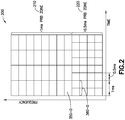
- the starting point for an exemplary embodiment is to assume that the PRBs of the frequency domain are divided into two distinct zones: one zone for the 1ms TTI, and another one for the short TTI. This is illustrated by FIG. 2 , which shows a time-frequency resource space 200 for downlink communications.
- the resource space 200 includes a 1ms PRB zone 210, where each PRB has a TTI of 1ms, and includes a 0.5ms PRB zone 220 where each PRB has a TTI of 0.5ms.
- the frequency range is illustrated by the y axis and is divided into the two zones 210, 220.
- PRB zones could be allocated to the different TTI lengths so that the UE knows the TTI length the UE is going to use.
- control information could explicitly give the TTI length.
- legacy PDCCH region would be reserved for legacy PDCCH, thus 2 symbol TTI would only start in the PDSCH region. Then the legacy PDCCH could still be used for scheduling the first 2 OFDM symbols of shorter TTI following the PDCCH region.
- a first downlink control information for the first 0.5ms TTI is followed by a second downlink control information for the second 0.5ms TTI.
- a legacy PDCCH region can be used to schedule both 1ms TTI PDSCH and shorter TTI PDSCH (e.g., the few OFDM symbol(s) following the legacy PDCCH region, the first 0.5ms within the 1ms in this example).
- a shorter TTI is scheduled by the shorter TTI zone.
- Another possible way is both the first 0.5ms and second 0.5ms are scheduled by PDCCH in the 0.5ms PRB zone.
- TTI length can be dynamically changed between shorter TTI and legacy TTI, but the UE 110 only operates with one TTI length at a point in time.
- the UE shall monitor PDCCH of a shorter TTI zone unless 1ms TTI PDSCH is scheduled, which covers the whole subframe in the time domain. That is, in an exemplary embodiment:
- reception of the PDSCH scheduled by legacy PDCCH at the beginning of the subframe takes precedence over PDCCH monitoring of the later OFDM symbols for shorter TTI.
- the eNB 170 implementation should ensure the eNB does not schedule both TTI lengths (in the 1ms TTI PRB zone 210 and the 0.5ms TTI PRB zone) at the same subframe, otherwise the UE 110 will miss one of them.
- the downlink control information can correspond to PDCCH or any scheduling information such as DL or UL control information.
- PDSCH here only refers to PDSCH scheduled by PDCCH addressed to UE's C-RNTI, other than PDSCH scheduled by PDCCH addressed to P-RNTI or SI-RNTI which is for paging and system information, respectively.
- the requirement specified in 3GPP TS 36.302 for simultaneous reception of PDCCH address to P-RNTI/SI-RNTI/C-RNTI should still be applicable with mixed TTI length, e.g., when the UE is reading PDSCH for SIB with 1ms TTI length scheduled by PDCCH addressed SI-RNTI, it should still be possible to schedule the UE with either 1ms or 0.5ms TTI length with PDCCH addressed to C-RNTI.
- PDCCH here covers both PDCCH and EPDCCH.
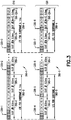
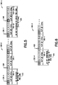
- FIG. 3 is an illustration of such a legacy LTE frame structure 310 and an LTE frame structure 320 with short TTI, where both frame structures are for FDD.
- FIG. 3 is zoom in of the 1ms subframe in FIG. 2 , where 350 is in the 1ms TTI zone and 360 is the 0.5ms TTI zone.
- the LTE FDD subframe 350-0 has slots 355-0 and 355-1
- the LTE FDD subframe 350-1 has slots 355-2 and 355-3 (355-3 is not shown), ...
- the LTE FDD subframe 350-k has slots 355-2k and 355-(2k+1).
- the new LTE frame structure 320 includes k+1 LTE FDD subframes 360-0 through 360-k, each of which has two slots, each of which is a TTI of 0.5ms in duration.
- the LTE FDD subframe 360-0 has slots 365-0 and 365-1
- the LTE FDD subframe 360-1 has slots 365-2 and 365-3 (365-3 is not shown)
- the LTE FDD subframe 360-k has slots 365-2k and 365-(2k+1).
- Each slot 355, 365 has seven OFDM symbols, numbered 0-6 for a first slot (e.g., 355-0 or 365-0) and numbered 7-13 for a second slot (e.g., 355-1 or 365-1).
- the UE 110 may read the PDCCH for the LTE FDD subframes 350 at the locations 330-1, 330-2, and 330-3, which means the UE 110 may read the PDCCH for the OFDM symbols 0, 1, or 2 (of 14 OFDM symbols) for each LTE FDD subframe 350.
- the UE 110 may read the PDCCH for the LTE FDD subframes 360 at the locations 330-4, 330-5, 330-6, 330-7, and 330-8, which means the UE 110 may read the PDCCH for the OFDM symbols 0, 1, or 7 (of OFDM symbols 0 to 13) for each LTE FDD subframe 360.
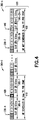
- Rule 1 If the UE 110 is scheduled by the first downlink control information in the 1ms TTI PRB zone 210, the UE 110 skips the second downlink control information. From the perspective of the eNB 170, the eNB 170 does not schedule the UE 110 in the second 0.5ms TTI if the UE 110 is scheduled in the 1ms TTI zone.
- FIG. 4 is an illustration of a new LTE frame structure and illustrates an example of a possible rule (Rule 1) for operating a UE efficiently and managing an interaction between PRB zones and downlink control information for scheduling.
- This example shows the new LTE FDD subframe 360-0 of FIG. 3 and the new LTE FDD subframe 360-k.
- the UE 110 because the UE 110 is scheduled (as illustrated by reference number 410) by the first downlink control information in the 1ms TTI PRB zone 210 (that is, in LTE FDD subframe 350-0), the UE 110 skips (as illustrated by reference number 420) reading the PDCCH in the OFDM symbol 7 of the slot 365-1.
- the UE 110 would read the PDCCH in OFDM symbols 0, 1, and/or 2 in slot 355-0 of legacy LTE FDD subframe 350-0 to determine the scheduling, and the scheduling typically includes scheduling the UE 110 to read the PDSCH of subsequent OFDM symbol(s).
- the scheduling typically includes scheduling the UE 110 to read the PDSCH of subsequent OFDM symbol(s).
- the UE 110 reads (as illustrated by reference 440) the PDCCH in the OFDM symbol 7 of the slot 365-(2k+1).
- the UE 110 also needs to read the second downlink control information. From the perspective of the eNB 170, the eNB 170 may schedule the UE 110 in the second 0.5ms TTI, if UE is scheduled in the first 0.5ms TTI.
- FIG. 5 provides an example of Rule 2.
- This example shows the new LTE FDD subframe 360-0 and the new LTE FDD subframe 360-k of FIG. 3 .
- the UE 110 is scheduled (as illustrated by reference number 510) by the first downlink control information in the 0.5ms TTI PRB zone 220 (that is, in the OFDM symbols 0 and 1 of the new LTE FDD subframe 360-0), the UE 110 reads (as illustrated by reference number 520) the PDCCH in the OFDM symbol 7 of the slot 365-1.
- Rule 2 and 3 it could be that the UE is independently schedulable in the first and/or second 0.5ms TTI. If the first 0.5ms is not scheduled, the UE should still read the second 0.5ms TTI, in an exemplary embodiment.
- FIG. 6 is used to provide an example of Rule 3. This example shows the new LTE FDD subframe 360-0 of FIG. 3 .
- the UE 110 is not scheduled (as illustrated by reference number 610) by the first downlink control information in the 0.5ms TTI PRB zone 220 (that is, in the OFDM symbols 0 and 1 of the new LTE FDD subframe 360-0), the UE 110 reads (as illustrated by reference number 620) the PDCCH in the OFDM symbol 7 of the slot 365-1.
- Rule 4 If the UE 110 is scheduled by the first downlink control information in the 1ms TTI PRB zone 210, the UE also reads the first and/or the second downlink control information (from the 0.5ms TTI PRB zone 210) and if scheduled decodes the PDSCH of 1ms TTI and 0.5ms TTI simultaneously.
- Rule 4 could be configured, e.g., by RRC signaling by the network. Additionally, only a subset of the rules could be used, either by fixing them in specifications or configuring them by RRC. Changing of TTI zones could be performed via system information or configured via dedicated RRC signaling, i.e., which is not that dynamic.
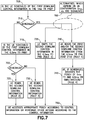
- FIG. 7 this figure is a logic flow diagram performed by a UE scheduled with mixed TTI length.
- This figure further illustrates the operation of an exemplary method, a result of execution of computer program instructions embodied on a computer readable memory, functions performed by logic implemented in hardware, and/or interconnected means for performing functions in accordance with exemplary embodiments.
- the mixed TTI length operation module 140 may include multiples ones of the blocks in FIG. 7 , where each included block is an interconnected means for performing the function in the block.
- the blocks in FIG. 7 are assumed to be performed by the UE 110, e.g., under control of the mixed TTI length operation module 140 at least in part.
- FIG. 7 includes all the rules as described above, but this is merely for exposition, and some rules may not be included in certain implementations.
- the UE 110 reads the first and/or the second downlink control information (from the 0.5ms TTI PRB zone 210).
- the UE in block 743 if scheduled, decodes the PDSCH of 1ms TTI and 0.5ms TTI simultaneously. For both blocks 740 and 743, see the description for Rule 4.
- the UE 110 determines if the UE scheduled by the first downlink control information in the 0.5ms TTI PRB 220.
- the first 0.5ms TTI either via legacy PDCCH, or via 0.5ms zone PDCCH, but should be no need to read both in parallel.
- PDCCH will indicate PDSCH is 1ms or 0.5ms. This step is performed by the UE searching for control information in the 0.5ms TTI PRB, and if the UE finds the control information, the UE then determines the UE has been scheduled.
- the UE accesses the appropriate PDSCH according to the control information or performs other actions corresponding to the control information.
- PDCCH can be used for initiating RACH (with PDCCH order), or for SPS activation/deactivation, and the like.
- the appropriate PDSCH could be in the 1ms TTI PRB 210 or the 0.5ms TTI PRB 220.
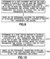
- FIG. 8 this figure is a logic flow diagram performed by a base station for scheduling of UEs with mixed TTI length.
- This figure further illustrates the operation of an exemplary method, a result of execution of computer program instructions embodied on a computer readable memory, functions performed by logic implemented in hardware, and/or interconnected means for performing functions in accordance with exemplary embodiments.
- the mixed TTI length scheduling module 150 may include multiples ones of the blocks in FIG. 8 , where each included block is an interconnected means for performing the function in the block.
- the blocks in FIG. 8 are assumed to be performed by a base station such as eNB 170, e.g., under control of the mixed TTI length scheduling module 150 at least in part.
- all rules above are shown in FIG. 8 , although this is merely exemplary.
- whether the eNB 170 can schedule the UE in the second 0.5ms slot should not depend on whether the UE is scheduled in the first 0.5ms slot. While the UE monitors PDCCH, this does not mean the eNB has to schedule the UE. Instead, this only means the eNB can schedule the UE if eNB decides to schedule the UE.
- FIG. 8 below considers these steps to be positive steps of scheduling or not scheduling the UE, but this is for ease of exposition only, and the eNB could instead consider the second 0.5ms TTI as schedulable and transmit PDCCH to the UE if a determination is made to schedule the UE.
- the eNB 170 determines (block 840) whether to schedule the UE in one or both of the first or second slots in the 0.5ms TTI PRB zone 210, and if scheduled, transmits (block 843) control information in one or both of the first or second slots in the 0.5ms TTI PRB zone 210. See the description of Rule 4 above. The UE in response would perform blocks 740 and 743.
- the eNB 170 in block 855, may transmit on an appropriate PDSCH of 1ms TTI or 0.5ms TTI according to the control information or perform other actions according to the control information.
- FIG. 9 this figure is a logic flow diagram performed by a UE scheduled with mixed TTI length.
- This figure further illustrates the operation of an exemplary method, a result of execution of computer program instructions embodied on a computer readable memory, functions performed by logic implemented in hardware, and/or interconnected means for performing functions in accordance with exemplary embodiments.
- the mixed TTI length operation module 140 may include multiples ones of the blocks in FIG. 9 , where each included block is an interconnected means for performing the function in the block.
- the blocks in FIG. 9 are assumed to be performed by the UE 110, e.g., under control of the mixed TTI length operation module 140 at least in part.
- a method includes determining (block 910) by a user equipment whether the user equipment is scheduled in one or more time frequency resources of a first transmission time interval or in one or more time frequency resources of a second transmission time interval, where the second transmission time interval is shorter than the first transmission time interval.
- the method includes (block 920), based on the determining, adjusting the monitoring of scheduling opportunities within a duration of the first transmission time interval.
- a technical effect and advantage of one or more of the example embodiments disclosed herein is improved scheduling mechanisms, taking better advantage of the shorter TTI resolution for those UEs that benefit the most out of it.
- Another technical effect and advantage of one or more of the example embodiments disclosed herein is as a UE power saving mechanism (as the UE is allowed to skip reading certain PDCCH, when the UE knows that the UE will not be scheduled).
- Another technical effect and advantage of one or more of the example embodiments disclosed herein is improved reliability of 1ms TTI scheduling.
- Embodiments herein may be implemented in software (executed by one or more processors), hardware (e.g., an application specific integrated circuit), or a combination of software and hardware.
- the software e.g., application logic, an instruction set
- a "computer-readable medium” may be any media or means that can contain, store, communicate, propagate or transport the instructions for use by or in connection with an instruction execution system, apparatus, or device, such as a computer, with one example of a computer described and depicted, e.g., in FIG. 1 .
- a computer-readable medium may comprise a computer-readable storage medium (e.g., memories 125, 155, 171 or other device) that may be any media or means that can contain, store, and/or transport the instructions for use by or in connection with an instruction execution system, apparatus, or device, such as a computer.
- a computer-readable storage medium does not comprise propagating signals.
- the different functions discussed herein may be performed in a different order and/or concurrently with each other. Furthermore, if desired, one or more of the above-described functions may be optional or may be combined.
Landscapes
- Engineering & Computer Science (AREA)
- Signal Processing (AREA)
- Computer Networks & Wireless Communication (AREA)
- Quality & Reliability (AREA)
- Mobile Radio Communication Systems (AREA)
Claims (15)
- Teilnehmereinrichtung, die Folgendes umfasst:ein Mittel zum Bestimmen (910), ob die Teilnehmereinrichtung in einer oder mehreren Zeitfrequenzressourcen eines ersten Übertragungszeitintervalls oder in einer oder mehreren Zeitfrequenzressourcen eines zweiten Übertragungszeitintervalls geplant ist, wo das zweite Übertragungszeitintervall kürzer ist als das erste Übertragungszeitintervall; undein Mittel zum Anpassen (920) des Überwachens von Planungsgelegenheiten innerhalb einer Dauer des ersten Übertragungszeitintervalls auf Basis des Bestimmens.
- Teilnehmereinrichtung nach Anspruch 1, wobei:die eine oder die mehreren Zeitfrequenzressourcen des zweiten Übertragungszeitintervalls mindestens eine erste und eine zweite Stelle umfassen, an denen die Teilnehmereinrichtung Planungsgelegenheiten überwachen kann;das Mittel zum Bestimmen, ob die Teilnehmereinrichtung geplant ist, ferner ein Mittel zum Bestimmen, dass die Teilnehmereinrichtung in einer Zeitfrequenzressource des ersten Übertragungszeitintervalls geplant ist, umfasst; unddas Mittel zum Anpassen ferner ein Mittel zum Überspringen einer Planungsgelegenheit an der zweiten Stelle im zweiten Übertragungszeitintervall umfasst.
- Teilnehmereinrichtung nach Anspruch 1, wobei:die eine oder die mehreren Zeitfrequenzressourcen des zweiten Übertragungszeitintervalls mindestens eine erste und eine zweite Stelle umfassen, an denen die Teilnehmereinrichtung Planungsgelegenheiten überwachen kann;das Mittel zum Bestimmen, ob die Teilnehmereinrichtung geplant ist, ferner ein Mittel zum Bestimmen, dass die Teilnehmereinrichtung in einer Zeitfrequenzressource des ersten Übertragungszeitintervalls geplant ist, umfasst; unddas Mittel zum Anpassen ferner ein Mittel zum Lesen eines physischen Downlinksteuerkanals für die erste Stelle, die zweite Stelle oder sowohl die erste als auch die zweite Stelle umfasst.
- Teilnehmereinrichtung nach Anspruch 3, die ferner Folgendes umfasst:
in Reaktion auf die Planung an der ersten Stelle, der zweiten Stelle oder sowohl der ersten als auch der zweiten Stelle ein Mittel zum gleichzeitigen Decodieren von Steuerinformationen in einem physischen Downlinksteuerkanal der ersten Zeitfrequenzressource und von Steuerinformationen in einem physischen Downlinksteuerkanal der zweiten Zeitfrequenzressource. - Teilnehmereinrichtung nach Anspruch 2 oder 3, wobei die Teilnehmereinrichtung dazu ausgelegt ist, auf Basis einer Teilnehmereinrichtungsauslegung zu bestimmen, nur eines des Überspringens oder des Lesens durchzuführen.
- Teilnehmereinrichtung nach Anspruch 5, die ferner ein Mittel zum Empfangen einer Anzeige der Teilnehmereinrichtungsauslegung aus einer Funkressourcensteuersignalisierung umfasst.
- Teilnehmereinrichtung nach Anspruch 1, wobei:die eine oder die mehreren Zeitfrequenzressourcen des zweiten Übertragungszeitintervalls mindestens eine erste und eine zweite Stelle umfassen, an denen die Teilnehmereinrichtung Planungsgelegenheiten überwachen kann;das Mittel zum Bestimmen, ob die Teilnehmereinrichtung geplant ist, ferner ein Mittel zum Bestimmen, dass die Teilnehmereinrichtung nicht in einer Zeitfrequenzressource des ersten Übertragungszeitintervalls geplant ist, sondern in einer Zeitfrequenzressource des zweiten Übertragungszeitintervalls geplant ist, umfasst; unddas Mittel zum Anpassen ferner ein Mittel zum Lesen eines physischen Downlinksteuerkanals für die zweite Stelle im zweiten Übertragungszeitintervall umfasst.
- Teilnehmereinrichtung nach Anspruch 1, wobei:die eine oder die mehreren Zeitfrequenzressourcen des zweiten Übertragungszeitintervalls mindestens eine erste und eine zweite Stelle umfassen, an denen die Teilnehmereinrichtung Planungsgelegenheiten überwachen kann;das Mittel zum Bestimmen, ob die Teilnehmereinrichtung geplant ist, ferner ein Mittel zum Bestimmen, dass die Teilnehmereinrichtung nicht in einer Zeitfrequenzressource des ersten Übertragungszeitintervalls geplant ist und nicht in einer Zeitfrequenzressource des zweiten Übertragungszeitintervalls geplant ist, umfasst; unddas Mittel zum Anpassen ferner ein Mittel zum Lesen eines physischen Downlinksteuerkanals für die zweite Stelle im zweiten Übertragungszeitintervall umfasst.
- Teilnehmereinrichtung nach einem der Ansprüche 2 bis 8, wobei die Stellen Stellen in physischen Ressourcenblöcken umfassen.
- Teilnehmereinrichtung nach Anspruch 9, wobei jede Stelle ein oder mehrere orthogonale Frequenzmultiplexingsymbole umfasst.
- Verfahren, das Folgendes umfasst:Bestimmen (910) durch eine Teilnehmereinrichtung, ob die Teilnehmereinrichtung in einer oder mehreren Zeitfrequenzressourcen eines ersten Übertragungszeitintervalls oder in einer oder mehreren Zeitfrequenzressourcen eines zweiten Übertragungszeitintervalls geplant ist, wo das zweite Übertragungszeitintervall kürzer ist als das erste Übertragungszeitintervall; undAnpassen (920) des Überwachens von Planungsgelegenheiten innerhalb einer Dauer des ersten Übertragungszeitintervalls durch die Teilnehmereinrichtung auf Basis des Bestimmens.
- Verfahren nach Anspruch 11, wobei:die eine oder die mehreren Zeitfrequenzressourcen des zweiten Übertragungszeitintervalls mindestens eine erste und eine zweite Stelle umfassen, an denen die Teilnehmereinrichtung Planungsgelegenheiten überwachen kann;das Bestimmen durch die Teilnehmereinrichtung, ob die Teilnehmereinrichtung geplant ist, ferner das Bestimmen, dass die Teilnehmereinrichtung in einer Zeitfrequenzressource des ersten Übertragungszeitintervalls geplant ist, umfasst; unddas Anpassen durch die Teilnehmereinrichtung ferner das Lesen eines physischen Downlinksteuerkanals für die erste Stelle, die zweite Stelle oder sowohl die erste als auch die zweite Stelle durch die Teilnehmereinrichtung umfasst.
- Verfahren nach Anspruch 12, wobei die Stellen Stellen in physischen Ressourcenblöcken umfassen.
- Verfahren nach Anspruch 13, wobei jede Stelle ein oder mehrere orthogonale Frequenzmultiplexingsymbole umfasst.
- Nichttransitorisches computerlesbares Medium, auf dem Anweisungen codiert sind, die, wenn sie in Hardware ausgeführt werden, einen Prozess mindestens gemäß dem Folgenden durchführen:Bestimmen (910) durch eine Teilnehmereinrichtung, ob die Teilnehmereinrichtung in einer oder mehreren Zeitfrequenzressourcen eines ersten Übertragungszeitintervalls oder in einer oder mehreren Zeitfrequenzressourcen eines zweiten Übertragungszeitintervalls geplant ist, wo das zweite Übertragungszeitintervall kürzer ist als das erste Übertragungszeitintervall; undAnpassen (920) des Überwachens von Planungsgelegenheiten innerhalb einer Dauer des ersten Übertragungszeitintervalls durch die Teilnehmereinrichtung auf Basis des Bestimmens.
Applications Claiming Priority (2)
| Application Number | Priority Date | Filing Date | Title |
|---|---|---|---|
| US201562249570P | 2015-11-02 | 2015-11-02 | |
| PCT/FI2016/050747 WO2017077179A1 (en) | 2015-11-02 | 2016-10-25 | Scheduling ues with mixed tti length |
Publications (3)
| Publication Number | Publication Date |
|---|---|
| EP3372007A1 EP3372007A1 (de) | 2018-09-12 |
| EP3372007A4 EP3372007A4 (de) | 2019-05-08 |
| EP3372007B1 true EP3372007B1 (de) | 2021-07-21 |
Family
ID=58661579
Family Applications (1)
| Application Number | Title | Priority Date | Filing Date |
|---|---|---|---|
| EP16861670.4A Active EP3372007B1 (de) | 2015-11-02 | 2016-10-25 | Zeitplanung von ues mit gemischter tti-länge |
Country Status (3)
| Country | Link |
|---|---|
| US (1) | US10904903B2 (de) |
| EP (1) | EP3372007B1 (de) |
| WO (1) | WO2017077179A1 (de) |
Families Citing this family (15)
| Publication number | Priority date | Publication date | Assignee | Title |
|---|---|---|---|---|
| ES2773029T3 (es) * | 2015-11-03 | 2020-07-09 | Lg Electronics Inc | Método para transmitir un canal de control de enlace ascendente en un sistema de comunicación inalámbrico y dispositivo para el mismo |
| US10868645B2 (en) * | 2015-11-06 | 2020-12-15 | Huawei Technologies Co., Ltd. | Method and base station for transmitting downlink data |
| US10660084B2 (en) * | 2016-01-26 | 2020-05-19 | Sony Corporation | Terminal device, base station device, and communication method |
| CN108476434B (zh) | 2016-02-05 | 2021-08-10 | 松下电器(美国)知识产权公司 | 基站、终端和通信方法 |
| CN108702755B (zh) * | 2016-02-29 | 2023-05-30 | 株式会社Ntt都科摩 | 终端、基站、系统以及无线通信方法 |
| EP3424174A1 (de) * | 2016-03-04 | 2019-01-09 | Telefonaktiebolaget LM Ericsson (PUBL) | Kurzes tti in speziellen unterrahmen von ttd-kommunikationssystemen |
| US20170265169A1 (en) * | 2016-03-10 | 2017-09-14 | Qualcomm Incorporated | Methods and apparatus for resource management for ultra low latency (ull) and legacy transmissions |
| US11310809B2 (en) * | 2016-05-04 | 2022-04-19 | Qualcomm Incorporated | Techniques for using a portion of a transmission time interval to transmit a transmission that is shorter than a duration of the transmission time interval |
| CN106793136B (zh) * | 2016-05-09 | 2018-11-16 | 北京展讯高科通信技术有限公司 | 用户设备及其数据传输方法 |
| WO2017193559A1 (zh) * | 2016-05-12 | 2017-11-16 | 华为技术有限公司 | 数据传输方法及装置 |
| JP6790124B2 (ja) * | 2016-05-13 | 2020-11-25 | テレフオンアクチーボラゲット エルエム エリクソン(パブル) | アダプティブ送信時間間隔長 |
| CN109076541B (zh) | 2016-05-13 | 2023-01-24 | 瑞典爱立信有限公司 | 用于在tdd中引入短tti的子框架选择 |
| US10609758B2 (en) | 2016-08-12 | 2020-03-31 | Motorola Mobility Llc | Methods, devices, and systems for discontinuous reception for a shortened transmission time interval and processing time |
| US10205581B2 (en) * | 2016-09-22 | 2019-02-12 | Huawei Technologies Co., Ltd. | Flexible slot architecture for low latency communication |
| US20180199287A1 (en) * | 2017-01-06 | 2018-07-12 | Lg Electronics Inc. | Method and user equipment for receiving downlink signals |
Citations (1)
| Publication number | Priority date | Publication date | Assignee | Title |
|---|---|---|---|---|
| WO2014189429A1 (en) * | 2013-05-21 | 2014-11-27 | Telefonaktiebolaget L M Ericsson (Publ) | Improved tti switching |
Family Cites Families (13)
| Publication number | Priority date | Publication date | Assignee | Title |
|---|---|---|---|---|
| JP4343926B2 (ja) * | 2006-02-08 | 2009-10-14 | 株式会社エヌ・ティ・ティ・ドコモ | 送信装置および送信方法 |
| US8811335B2 (en) * | 2007-04-20 | 2014-08-19 | Qualcomm Incorporated | Method and apparatus for dynamic adjustment of uplink transmission time |
| US8767644B2 (en) * | 2010-01-15 | 2014-07-01 | Telefonaktiebolaget Lm Ericsson (Publ) | Method and apparatus for contention-based granting in a wireless communication network |
| JP5990545B2 (ja) * | 2011-02-21 | 2016-09-14 | サムスン エレクトロニクス カンパニー リミテッド | 無線通信システムにおける端末の省電力方法及び装置 |
| US8830947B2 (en) * | 2011-08-30 | 2014-09-09 | Broadcom Corporation | Channel sensing in uplink transmission |
| TWI632823B (zh) * | 2012-08-23 | 2018-08-11 | 內數位專利控股公司 | 在無線系統中多層操作之實體層操作 |
| US9131498B2 (en) | 2012-09-12 | 2015-09-08 | Futurewei Technologies, Inc. | System and method for adaptive transmission time interval (TTI) structure |
| US10200137B2 (en) * | 2013-12-27 | 2019-02-05 | Huawei Technologies Co., Ltd. | System and method for adaptive TTI coexistence with LTE |
| CN104754587A (zh) * | 2013-12-31 | 2015-07-01 | 中兴通讯股份有限公司 | 一种lte系统干扰协调的方法及装置 |
| EP3195508A1 (de) | 2014-09-08 | 2017-07-26 | Interdigital Patent Holdings, Inc. | Systeme und verfahren für betrieb mit verschieden langen übertragungszeitintervallen (tti) |
| US10349363B2 (en) * | 2014-11-26 | 2019-07-09 | Nokia Solutions And Networks Oy | Methods and apparatus for automatic configuration of a wireless access point |
| US20180176956A1 (en) * | 2015-02-20 | 2018-06-21 | Telefonaktiebolaget Lm Ericsson (Publ) | LBT Patterns for Wireless Communication |
| WO2017041207A1 (en) * | 2015-09-07 | 2017-03-16 | Apple Inc. | Device and method for adaptive link adaptation |
-
2016
- 2016-10-25 EP EP16861670.4A patent/EP3372007B1/de active Active
- 2016-10-25 WO PCT/FI2016/050747 patent/WO2017077179A1/en not_active Ceased
- 2016-10-25 US US15/771,660 patent/US10904903B2/en active Active
Patent Citations (1)
| Publication number | Priority date | Publication date | Assignee | Title |
|---|---|---|---|---|
| WO2014189429A1 (en) * | 2013-05-21 | 2014-11-27 | Telefonaktiebolaget L M Ericsson (Publ) | Improved tti switching |
Also Published As
| Publication number | Publication date |
|---|---|
| EP3372007A4 (de) | 2019-05-08 |
| WO2017077179A1 (en) | 2017-05-11 |
| US10904903B2 (en) | 2021-01-26 |
| US20180324834A1 (en) | 2018-11-08 |
| EP3372007A1 (de) | 2018-09-12 |
Similar Documents
| Publication | Publication Date | Title |
|---|---|---|
| EP3372007B1 (de) | Zeitplanung von ues mit gemischter tti-länge | |
| US20240292425A1 (en) | Methods and Apparatus for Utilizing Short Transmission Time Intervals in a Wireless Communications Network | |
| US9270409B2 (en) | System and method for handling of an uplink transmission collision with an ACK/NACK signal | |
| CN111801922B (zh) | 用于支持v2x业务的控制信道结构设计 | |
| US12035418B2 (en) | Methods and apparatus for support of reduced capability devices in wireless communication | |
| US11006462B2 (en) | System and method for handling of an uplink transmission collision with an ACK/NACK signal | |
| US20230269778A1 (en) | Indication of tbs scaling and repetition for msg4 pdsch | |
| JP2018074601A (ja) | オープン発見リソースとセルラリソースとの衝突を回避する方法 | |
| US10128992B2 (en) | Apparatus and method for communication with time-shifted subbands | |
| JP2020523902A (ja) | 通信方法、ネットワークデバイス、およびユーザ機器 | |
| US20140274011A1 (en) | Method and apparatus for controlling operation of a user equipment based on physical layer parameters | |
| JP2021512518A (ja) | データ伝送方法及び端末装置 | |
| US20250151046A1 (en) | Method and apparatus for pucch transmission | |
| WO2020029070A1 (en) | Method, apparatus and computer readable media for resource allocation | |
| US10952100B2 (en) | UL scheduling timing with short TTIs in TDD | |
| US11184118B2 (en) | Methods and devices for hybrid automatic repeat request acknowledgement/non-acknowledgement bundling | |
| US20250343641A1 (en) | Method and apparatus of uplink transmission | |
| WO2024217784A1 (en) | User equipment measurement restrictions to protect critical data receptions | |
| CN120034957A (zh) | 信道重复传输方法、装置、ue、网络侧设备及存储介质 |
Legal Events
| Date | Code | Title | Description |
|---|---|---|---|
| STAA | Information on the status of an ep patent application or granted ep patent |
Free format text: STATUS: THE INTERNATIONAL PUBLICATION HAS BEEN MADE |
|
| PUAI | Public reference made under article 153(3) epc to a published international application that has entered the european phase |
Free format text: ORIGINAL CODE: 0009012 |
|
| STAA | Information on the status of an ep patent application or granted ep patent |
Free format text: STATUS: REQUEST FOR EXAMINATION WAS MADE |
|
| 17P | Request for examination filed |
Effective date: 20180508 |
|
| AK | Designated contracting states |
Kind code of ref document: A1 Designated state(s): AL AT BE BG CH CY CZ DE DK EE ES FI FR GB GR HR HU IE IS IT LI LT LU LV MC MK MT NL NO PL PT RO RS SE SI SK SM TR |
|
| AX | Request for extension of the european patent |
Extension state: BA ME |
|
| DAV | Request for validation of the european patent (deleted) | ||
| DAX | Request for extension of the european patent (deleted) | ||
| A4 | Supplementary search report drawn up and despatched |
Effective date: 20190410 |
|
| RIC1 | Information provided on ipc code assigned before grant |
Ipc: H04W 72/04 20090101ALN20190404BHEP Ipc: H04W 72/12 20090101AFI20190404BHEP |
|
| RAP1 | Party data changed (applicant data changed or rights of an application transferred) |
Owner name: NOKIA TECHNOLOGIES OY |
|
| STAA | Information on the status of an ep patent application or granted ep patent |
Free format text: STATUS: EXAMINATION IS IN PROGRESS |
|
| 17Q | First examination report despatched |
Effective date: 20200511 |
|
| REG | Reference to a national code |
Ref country code: DE Ref legal event code: R079 Ref document number: 602016061075 Country of ref document: DE Free format text: PREVIOUS MAIN CLASS: H04W0028060000 Ipc: H04W0072040000 |
|
| RIC1 | Information provided on ipc code assigned before grant |
Ipc: H04L 5/00 20060101ALI20201015BHEP Ipc: H04W 72/12 20090101ALI20201015BHEP Ipc: H04W 72/04 20090101AFI20201015BHEP |
|
| GRAP | Despatch of communication of intention to grant a patent |
Free format text: ORIGINAL CODE: EPIDOSNIGR1 |
|
| STAA | Information on the status of an ep patent application or granted ep patent |
Free format text: STATUS: GRANT OF PATENT IS INTENDED |
|
| INTG | Intention to grant announced |
Effective date: 20201126 |
|
| GRAJ | Information related to disapproval of communication of intention to grant by the applicant or resumption of examination proceedings by the epo deleted |
Free format text: ORIGINAL CODE: EPIDOSDIGR1 |
|
| STAA | Information on the status of an ep patent application or granted ep patent |
Free format text: STATUS: EXAMINATION IS IN PROGRESS |
|
| GRAP | Despatch of communication of intention to grant a patent |
Free format text: ORIGINAL CODE: EPIDOSNIGR1 |
|
| STAA | Information on the status of an ep patent application or granted ep patent |
Free format text: STATUS: GRANT OF PATENT IS INTENDED |
|
| INTC | Intention to grant announced (deleted) | ||
| INTG | Intention to grant announced |
Effective date: 20210216 |
|
| GRAS | Grant fee paid |
Free format text: ORIGINAL CODE: EPIDOSNIGR3 |
|
| GRAA | (expected) grant |
Free format text: ORIGINAL CODE: 0009210 |
|
| STAA | Information on the status of an ep patent application or granted ep patent |
Free format text: STATUS: THE PATENT HAS BEEN GRANTED |
|
| AK | Designated contracting states |
Kind code of ref document: B1 Designated state(s): AL AT BE BG CH CY CZ DE DK EE ES FI FR GB GR HR HU IE IS IT LI LT LU LV MC MK MT NL NO PL PT RO RS SE SI SK SM TR |
|
| REG | Reference to a national code |
Ref country code: GB Ref legal event code: FG4D |
|
| REG | Reference to a national code |
Ref country code: CH Ref legal event code: EP |
|
| REG | Reference to a national code |
Ref country code: DE Ref legal event code: R096 Ref document number: 602016061075 Country of ref document: DE |
|
| REG | Reference to a national code |
Ref country code: AT Ref legal event code: REF Ref document number: 1413814 Country of ref document: AT Kind code of ref document: T Effective date: 20210815 |
|
| REG | Reference to a national code |
Ref country code: IE Ref legal event code: FG4D |
|
| REG | Reference to a national code |
Ref country code: EE Ref legal event code: FG4A Ref document number: E021316 Country of ref document: EE Effective date: 20210806 |
|
| REG | Reference to a national code |
Ref country code: LT Ref legal event code: MG9D |
|
| REG | Reference to a national code |
Ref country code: NL Ref legal event code: MP Effective date: 20210721 |
|
| PG25 | Lapsed in a contracting state [announced via postgrant information from national office to epo] |
Ref country code: BG Free format text: LAPSE BECAUSE OF FAILURE TO SUBMIT A TRANSLATION OF THE DESCRIPTION OR TO PAY THE FEE WITHIN THE PRESCRIBED TIME-LIMIT Effective date: 20211021 Ref country code: LT Free format text: LAPSE BECAUSE OF FAILURE TO SUBMIT A TRANSLATION OF THE DESCRIPTION OR TO PAY THE FEE WITHIN THE PRESCRIBED TIME-LIMIT Effective date: 20210721 Ref country code: HR Free format text: LAPSE BECAUSE OF FAILURE TO SUBMIT A TRANSLATION OF THE DESCRIPTION OR TO PAY THE FEE WITHIN THE PRESCRIBED TIME-LIMIT Effective date: 20210721 Ref country code: ES Free format text: LAPSE BECAUSE OF FAILURE TO SUBMIT A TRANSLATION OF THE DESCRIPTION OR TO PAY THE FEE WITHIN THE PRESCRIBED TIME-LIMIT Effective date: 20210721 Ref country code: FI Free format text: LAPSE BECAUSE OF FAILURE TO SUBMIT A TRANSLATION OF THE DESCRIPTION OR TO PAY THE FEE WITHIN THE PRESCRIBED TIME-LIMIT Effective date: 20210721 Ref country code: NL Free format text: LAPSE BECAUSE OF FAILURE TO SUBMIT A TRANSLATION OF THE DESCRIPTION OR TO PAY THE FEE WITHIN THE PRESCRIBED TIME-LIMIT Effective date: 20210721 Ref country code: NO Free format text: LAPSE BECAUSE OF FAILURE TO SUBMIT A TRANSLATION OF THE DESCRIPTION OR TO PAY THE FEE WITHIN THE PRESCRIBED TIME-LIMIT Effective date: 20211021 Ref country code: PT Free format text: LAPSE BECAUSE OF FAILURE TO SUBMIT A TRANSLATION OF THE DESCRIPTION OR TO PAY THE FEE WITHIN THE PRESCRIBED TIME-LIMIT Effective date: 20211122 Ref country code: RS Free format text: LAPSE BECAUSE OF FAILURE TO SUBMIT A TRANSLATION OF THE DESCRIPTION OR TO PAY THE FEE WITHIN THE PRESCRIBED TIME-LIMIT Effective date: 20210721 Ref country code: SE Free format text: LAPSE BECAUSE OF FAILURE TO SUBMIT A TRANSLATION OF THE DESCRIPTION OR TO PAY THE FEE WITHIN THE PRESCRIBED TIME-LIMIT Effective date: 20210721 |
|
| PG25 | Lapsed in a contracting state [announced via postgrant information from national office to epo] |
Ref country code: PL Free format text: LAPSE BECAUSE OF FAILURE TO SUBMIT A TRANSLATION OF THE DESCRIPTION OR TO PAY THE FEE WITHIN THE PRESCRIBED TIME-LIMIT Effective date: 20210721 Ref country code: LV Free format text: LAPSE BECAUSE OF FAILURE TO SUBMIT A TRANSLATION OF THE DESCRIPTION OR TO PAY THE FEE WITHIN THE PRESCRIBED TIME-LIMIT Effective date: 20210721 Ref country code: GR Free format text: LAPSE BECAUSE OF FAILURE TO SUBMIT A TRANSLATION OF THE DESCRIPTION OR TO PAY THE FEE WITHIN THE PRESCRIBED TIME-LIMIT Effective date: 20211022 |
|
| REG | Reference to a national code |
Ref country code: DE Ref legal event code: R097 Ref document number: 602016061075 Country of ref document: DE |
|
| PG25 | Lapsed in a contracting state [announced via postgrant information from national office to epo] |
Ref country code: DK Free format text: LAPSE BECAUSE OF FAILURE TO SUBMIT A TRANSLATION OF THE DESCRIPTION OR TO PAY THE FEE WITHIN THE PRESCRIBED TIME-LIMIT Effective date: 20210721 |
|
| PLBE | No opposition filed within time limit |
Free format text: ORIGINAL CODE: 0009261 |
|
| STAA | Information on the status of an ep patent application or granted ep patent |
Free format text: STATUS: NO OPPOSITION FILED WITHIN TIME LIMIT |
|
| REG | Reference to a national code |
Ref country code: CH Ref legal event code: PL |
|
| PG25 | Lapsed in a contracting state [announced via postgrant information from national office to epo] |
Ref country code: SM Free format text: LAPSE BECAUSE OF FAILURE TO SUBMIT A TRANSLATION OF THE DESCRIPTION OR TO PAY THE FEE WITHIN THE PRESCRIBED TIME-LIMIT Effective date: 20210721 Ref country code: SK Free format text: LAPSE BECAUSE OF FAILURE TO SUBMIT A TRANSLATION OF THE DESCRIPTION OR TO PAY THE FEE WITHIN THE PRESCRIBED TIME-LIMIT Effective date: 20210721 Ref country code: RO Free format text: LAPSE BECAUSE OF FAILURE TO SUBMIT A TRANSLATION OF THE DESCRIPTION OR TO PAY THE FEE WITHIN THE PRESCRIBED TIME-LIMIT Effective date: 20210721 Ref country code: CZ Free format text: LAPSE BECAUSE OF FAILURE TO SUBMIT A TRANSLATION OF THE DESCRIPTION OR TO PAY THE FEE WITHIN THE PRESCRIBED TIME-LIMIT Effective date: 20210721 Ref country code: AL Free format text: LAPSE BECAUSE OF FAILURE TO SUBMIT A TRANSLATION OF THE DESCRIPTION OR TO PAY THE FEE WITHIN THE PRESCRIBED TIME-LIMIT Effective date: 20210721 |
|
| REG | Reference to a national code |
Ref country code: BE Ref legal event code: MM Effective date: 20211031 |
|
| 26N | No opposition filed |
Effective date: 20220422 |
|
| PG25 | Lapsed in a contracting state [announced via postgrant information from national office to epo] |
Ref country code: MC Free format text: LAPSE BECAUSE OF FAILURE TO SUBMIT A TRANSLATION OF THE DESCRIPTION OR TO PAY THE FEE WITHIN THE PRESCRIBED TIME-LIMIT Effective date: 20210721 |
|
| PG25 | Lapsed in a contracting state [announced via postgrant information from national office to epo] |
Ref country code: LU Free format text: LAPSE BECAUSE OF NON-PAYMENT OF DUE FEES Effective date: 20211025 Ref country code: IT Free format text: LAPSE BECAUSE OF FAILURE TO SUBMIT A TRANSLATION OF THE DESCRIPTION OR TO PAY THE FEE WITHIN THE PRESCRIBED TIME-LIMIT Effective date: 20210721 Ref country code: BE Free format text: LAPSE BECAUSE OF NON-PAYMENT OF DUE FEES Effective date: 20211031 |
|
| PG25 | Lapsed in a contracting state [announced via postgrant information from national office to epo] |
Ref country code: LI Free format text: LAPSE BECAUSE OF NON-PAYMENT OF DUE FEES Effective date: 20211031 Ref country code: CH Free format text: LAPSE BECAUSE OF NON-PAYMENT OF DUE FEES Effective date: 20211031 |
|
| PG25 | Lapsed in a contracting state [announced via postgrant information from national office to epo] |
Ref country code: IE Free format text: LAPSE BECAUSE OF NON-PAYMENT OF DUE FEES Effective date: 20211025 |
|
| PG25 | Lapsed in a contracting state [announced via postgrant information from national office to epo] |
Ref country code: HU Free format text: LAPSE BECAUSE OF FAILURE TO SUBMIT A TRANSLATION OF THE DESCRIPTION OR TO PAY THE FEE WITHIN THE PRESCRIBED TIME-LIMIT; INVALID AB INITIO Effective date: 20161025 |
|
| REG | Reference to a national code |
Ref country code: AT Ref legal event code: UEP Ref document number: 1413814 Country of ref document: AT Kind code of ref document: T Effective date: 20210721 |
|
| PG25 | Lapsed in a contracting state [announced via postgrant information from national office to epo] |
Ref country code: CY Free format text: LAPSE BECAUSE OF FAILURE TO SUBMIT A TRANSLATION OF THE DESCRIPTION OR TO PAY THE FEE WITHIN THE PRESCRIBED TIME-LIMIT Effective date: 20210721 |
|
| P01 | Opt-out of the competence of the unified patent court (upc) registered |
Effective date: 20230527 |
|
| PG25 | Lapsed in a contracting state [announced via postgrant information from national office to epo] |
Ref country code: MK Free format text: LAPSE BECAUSE OF FAILURE TO SUBMIT A TRANSLATION OF THE DESCRIPTION OR TO PAY THE FEE WITHIN THE PRESCRIBED TIME-LIMIT Effective date: 20210721 |
|
| PG25 | Lapsed in a contracting state [announced via postgrant information from national office to epo] |
Ref country code: MT Free format text: LAPSE BECAUSE OF FAILURE TO SUBMIT A TRANSLATION OF THE DESCRIPTION OR TO PAY THE FEE WITHIN THE PRESCRIBED TIME-LIMIT Effective date: 20210721 |
|
| PGFP | Annual fee paid to national office [announced via postgrant information from national office to epo] |
Ref country code: DE Payment date: 20240904 Year of fee payment: 9 |
|
| PGFP | Annual fee paid to national office [announced via postgrant information from national office to epo] |
Ref country code: AT Payment date: 20240925 Year of fee payment: 9 |
|
| PGFP | Annual fee paid to national office [announced via postgrant information from national office to epo] |
Ref country code: GB Payment date: 20250904 Year of fee payment: 10 |
|
| PGFP | Annual fee paid to national office [announced via postgrant information from national office to epo] |
Ref country code: FR Payment date: 20250908 Year of fee payment: 10 |
|
| PGFP | Annual fee paid to national office [announced via postgrant information from national office to epo] |
Ref country code: EE Payment date: 20250909 Year of fee payment: 10 |
|
| PG25 | Lapsed in a contracting state [announced via postgrant information from national office to epo] |
Ref country code: TR Free format text: LAPSE BECAUSE OF FAILURE TO SUBMIT A TRANSLATION OF THE DESCRIPTION OR TO PAY THE FEE WITHIN THE PRESCRIBED TIME-LIMIT Effective date: 20210721 |