EP3371393B1 - Construction de murs antisismiques - Google Patents
Construction de murs antisismiques Download PDFInfo
- Publication number
- EP3371393B1 EP3371393B1 EP16861735.5A EP16861735A EP3371393B1 EP 3371393 B1 EP3371393 B1 EP 3371393B1 EP 16861735 A EP16861735 A EP 16861735A EP 3371393 B1 EP3371393 B1 EP 3371393B1
- Authority
- EP
- European Patent Office
- Prior art keywords
- runner
- earthquake resistant
- earthquake
- wall construction
- fixing member
- Prior art date
- Legal status (The legal status is an assumption and is not a legal conclusion. Google has not performed a legal analysis and makes no representation as to the accuracy of the status listed.)
- Active
Links
- 238000010276 construction Methods 0.000 title claims description 112
- 238000000034 method Methods 0.000 claims description 14
- 239000010440 gypsum Substances 0.000 claims description 8
- 229910052602 gypsum Inorganic materials 0.000 claims description 8
- 238000004891 communication Methods 0.000 claims description 5
- 239000004568 cement Substances 0.000 claims description 2
- 239000011518 fibre cement Substances 0.000 claims 1
- 238000006073 displacement reaction Methods 0.000 description 21
- 238000012360 testing method Methods 0.000 description 18
- 230000006378 damage Effects 0.000 description 11
- 239000000463 material Substances 0.000 description 10
- 239000002356 single layer Substances 0.000 description 10
- 230000000694 effects Effects 0.000 description 7
- 230000008901 benefit Effects 0.000 description 6
- 238000004088 simulation Methods 0.000 description 6
- 239000011230 binding agent Substances 0.000 description 5
- 238000009434 installation Methods 0.000 description 5
- 238000006243 chemical reaction Methods 0.000 description 4
- 125000004122 cyclic group Chemical group 0.000 description 4
- 229910052751 metal Inorganic materials 0.000 description 4
- 239000002184 metal Substances 0.000 description 4
- 229910000831 Steel Inorganic materials 0.000 description 3
- 239000003365 glass fiber Substances 0.000 description 3
- 239000010959 steel Substances 0.000 description 3
- 229920002472 Starch Polymers 0.000 description 2
- 238000005452 bending Methods 0.000 description 2
- 239000000835 fiber Substances 0.000 description 2
- 238000005192 partition Methods 0.000 description 2
- 239000004033 plastic Substances 0.000 description 2
- 229920003023 plastic Polymers 0.000 description 2
- 239000008107 starch Substances 0.000 description 2
- 235000019698 starch Nutrition 0.000 description 2
- 238000006467 substitution reaction Methods 0.000 description 2
- 239000002023 wood Substances 0.000 description 2
- 239000011398 Portland cement Substances 0.000 description 1
- 208000027418 Wounds and injury Diseases 0.000 description 1
- 239000000853 adhesive Substances 0.000 description 1
- 230000001070 adhesive effect Effects 0.000 description 1
- 238000013459 approach Methods 0.000 description 1
- 230000015572 biosynthetic process Effects 0.000 description 1
- XFWJKVMFIVXPKK-UHFFFAOYSA-N calcium;oxido(oxo)alumane Chemical compound [Ca+2].[O-][Al]=O.[O-][Al]=O XFWJKVMFIVXPKK-UHFFFAOYSA-N 0.000 description 1
- IQYKECCCHDLEPX-UHFFFAOYSA-N chloro hypochlorite;magnesium Chemical compound [Mg].ClOCl IQYKECCCHDLEPX-UHFFFAOYSA-N 0.000 description 1
- 238000013461 design Methods 0.000 description 1
- 238000011156 evaluation Methods 0.000 description 1
- 238000002474 experimental method Methods 0.000 description 1
- 239000003292 glue Substances 0.000 description 1
- 208000014674 injury Diseases 0.000 description 1
- 230000010354 integration Effects 0.000 description 1
- GVALZJMUIHGIMD-UHFFFAOYSA-H magnesium phosphate Chemical compound [Mg+2].[Mg+2].[Mg+2].[O-]P([O-])([O-])=O.[O-]P([O-])([O-])=O GVALZJMUIHGIMD-UHFFFAOYSA-H 0.000 description 1
- 239000004137 magnesium phosphate Substances 0.000 description 1
- 229960002261 magnesium phosphate Drugs 0.000 description 1
- 229910000157 magnesium phosphate Inorganic materials 0.000 description 1
- 235000010994 magnesium phosphates Nutrition 0.000 description 1
- 239000000203 mixture Substances 0.000 description 1
- 229920002689 polyvinyl acetate Polymers 0.000 description 1
- 239000011118 polyvinyl acetate Substances 0.000 description 1
- 238000012545 processing Methods 0.000 description 1
- 238000011084 recovery Methods 0.000 description 1
- 230000002787 reinforcement Effects 0.000 description 1
- 229920002994 synthetic fiber Polymers 0.000 description 1
- 229920001059 synthetic polymer Polymers 0.000 description 1
- 238000010998 test method Methods 0.000 description 1
Images


Classifications
-
- E—FIXED CONSTRUCTIONS
- E04—BUILDING
- E04H—BUILDINGS OR LIKE STRUCTURES FOR PARTICULAR PURPOSES; SWIMMING OR SPLASH BATHS OR POOLS; MASTS; FENCING; TENTS OR CANOPIES, IN GENERAL
- E04H9/00—Buildings, groups of buildings or shelters adapted to withstand or provide protection against abnormal external influences, e.g. war-like action, earthquake or extreme climate
- E04H9/02—Buildings, groups of buildings or shelters adapted to withstand or provide protection against abnormal external influences, e.g. war-like action, earthquake or extreme climate withstanding earthquake or sinking of ground
- E04H9/021—Bearing, supporting or connecting constructions specially adapted for such buildings
-
- E—FIXED CONSTRUCTIONS
- E04—BUILDING
- E04B—GENERAL BUILDING CONSTRUCTIONS; WALLS, e.g. PARTITIONS; ROOFS; FLOORS; CEILINGS; INSULATION OR OTHER PROTECTION OF BUILDINGS
- E04B2/00—Walls, e.g. partitions, for buildings; Wall construction with regard to insulation; Connections specially adapted to walls
- E04B2/56—Load-bearing walls of framework or pillarwork; Walls incorporating load-bearing elongated members
- E04B2/58—Load-bearing walls of framework or pillarwork; Walls incorporating load-bearing elongated members with elongated members of metal
Definitions
- the present invention relates to an earthquake resistant wall construction according to claim 1; in particular to an earthquake resistant wall construction comprising an earthquake resistant insert that allows a construction board to move within runners.
- US patent publication number 20060032157 relates to a ceiling runner/upper runner that is specially designed for allowing movement of the ceiling relative to the floor without damaging the wall.
- the wall system includes a ceiling runner, a floor runner and studs that are mounted between the ceiling runner and the floor runner.
- the ceiling runner is loosely attached to the ceiling with fasteners and the floor runner is attached to the floor with fasteners.
- the ceiling runner defines multiple slots.
- the studs are placed in slots in the ceiling runner and are not rigidly connected with a fastener or a weld. The studs move within the slots thereby accommodating horizontal movement of the ceiling relative to the floor.
- the horizontal ceiling movement causes the fasteners to slide within the slots in the web of the ceiling runner.
- an earthquake resistant wall construction according to claim 1 is disclosed.
- the earthquake resistant wall construction comprises a first runner, a second runner and at least one earthquake resistant insert in communication with the first runner or the second runner and connected to at least one construction board.
- the earthquake resistant insert further comprises at least one elongate slot.
- the earthquake resistant insert is held in communication with the first or second runner via at least one first fixing member that passes through the elongate slot.
- the earthquake resistant insert is connected to the construction board on either side of the earthquake resistant insert using at least one second fixing member.
- an earthquake resistant insert comprising a first leg, second leg and a base.
- the first leg and second leg of the earthquake resistant insert extend perpendicularly from the base.
- the base further comprises at least one elongate slot for accommodating at least one first fixing member.
- a method according to claim 17 of constructing an earthquake resistant wall construction according to claim 1 comprises the steps of providing a first runner and a second runner, fixing the first and second runner to an adjacent surface using at least one third fixing member, sliding one or more studs to the runners by placing one end of the stud into the first runner and the other end of the stud into the second runner, placing an earthquake resistant insert between the studs in the first runner and/ or the second runner, fixing the earthquake resistant insert to the first and second runner through the first fixing member and attaching a construction board on either side of the earthquake resistant insert via at least one second fixing member.
- An earthquake resistant wall construction comprising earthquake resistant inserts placed in runners is disclosed.
- Such a construction is advantageous as it enables the construction of earthquake resistant walls, ceilings and other building elements without necessitating the installation of specialized runners.
- the earthquake resistant insert further comprises one or more elongate slots.
- the earthquake resistant inserts of the present invention move in relation to the runners, facilitated by the elongate slots, thus providing the construction walls with earthquake resistance.
- the connection between the runners and the adjacent surface of the building is not required to be mobile and traditional runners or channels can be used. Such a feature is advantageous as the cost of installation of the construction element may be lowered with increased installation ease.
- the movement of the earthquake resistant wall construction being controlled by the movement of the earthquake resistant insert relative to the runners may be advantageous as, in such an embodiment, said movement is governed by the length of the elongate slot and the friction between the runner and the earthquake resistant insert.
- the earthquake resistant insert and the runners are constructed from materials selected by the user and therefore the degree of friction between the two can be chosen to be within user defined parameters. This may not be the case in other systems, where the earthquake resistant construction moves relative to or slides against a preinstalled component, for example a concrete structure of the building.
- the earthquake resistant wall is non-loadbearing.
- Such an embodiment of the invention may be preferable as it may allow the construction of internal walls, ceilings, and other space dividing construction elements.
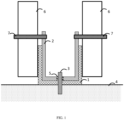
- FIG. 1 illustrates an exemplary runner 1 and an exemplary earthquake resistant insert 2.
- the earthquake resistant insert 2 is located inside the runner 1 via a first fixing member 3.
- the first fixing member 3 further anchors or holds the runner 1 in position with respect to the adjacent surface 4, most commonly a ceiling or floor.
- the earthquake resistant insert 2 is a U shaped member, and is sized to fit inside the runner 1.
- the U shaped earthquake resistant insert 2 may move well within a runner 1, whilst offering surfaces to which the construction board may be easily connected.
- the first fixing member 3 used to locate or position the earthquake resistant insert 2 inside the runner 1 is inserted through an elongate slot 5 in the earthquake resistant insert 2.
- the elongate slot 5 lies substantially parallel to the longitudinal length of the runner 1.
- the use of an elongate slot 5 in the earthquake resistant insert 2 allows the movement of the earthquake resistant insert 2 along the longitudinal length of the runner 1 in response to the movements associated with an earthquake event.
- the degree of travel which an earthquake resistant insert 2 may experience along the longitudinal length of the runner 1 may therefore be limited by the length of the elongate slot 5.
- the elongate slot 5 has a length of 60 mm, although lengths between at least 20 and 100 mm are envisaged.
- FIG. 1 depicts the fixation or attachment of a construction board 6, in this embodiment a plasterboard panel, to the earthquake resistant insert 2 via a second fixing member 7.
- the second fixing member 7 attaches the construction board 6 to the earthquake resistant insert 2, holding the construction board 6 in place relative to the earthquake resistant insert 2, on the outside of the runner 1. Therefore, in this embodiment, the construction board 6 is not held in a fixed position relative to the runner 1, and instead may move longitudinally along the length of the runner 1 concomitant with the movement of the earthquake resistant insert 2.
- Such an embodiment of the invention may be advantageous as a second fixing member 7 may provide a secure connection between the construction board 6 and the earthquake resistant insert 2, required to prevent damage to the earthquake resistant construction element during an earthquake event.
- the earthquake resistant insert 2 may preferably be located substantially within the runner 1. In one other embodiment, the earthquake resistant insert 2 extends above the runner 1. Such an embodiment may be preferable as the ability of the earthquake resistant insert 2 to move within the runner 1 may be substantially controlled by the friction between the earthquake resistant insert 2 and the runner 1. This material parameter may be controlled or chosen by the user upon installation of the earthquake resistant wall construction, and therefore may allow customization over the strength of an earthquake event which is required to cause the movement of the earthquake resistant insert 2 relative to the runner 1. Such an embodiment may also be preferable as it may prevent differences in the material or finish of any adjacent surface influencing the mobility of the earthquake resistant construction system in specific areas.
- the first fixing member 3 is a screw although bolts and the use of other fixing methods are also envisaged.
- the elongate slot 5 is wider than the first fixing member 3, but the head of the screw which forms the first fixing member 3 is wider than the elongate slot 5.
- the earthquake resistant insert 2 may travel longitudinally along the length of the runner 1, within the limits of the elongate slot 5, but is held by the head of the screw which forms the first fixing member 3 in communication with the runner 1.
- the second fixing member 7 may comprise a screw. In one other embodiment, the second fixing member 7 may comprise a bolt. In another embodiment, the second fixing member 7 may comprise a nail. In yet another embodiment, the construction board 6 may be connected to the earthquake resistant insert 2 using an adhesive or glue.
- the construction board 6 is movable connected to the runner 1, potentially increasing the resilience of the construction element without reducing its ability to move with the earth movements associated with an earthquake event.
- the use of earthquake resistant inserts 2 in communication with a ceiling may allow increased control over the movement of the earthquake resistant construction system; this movement may now be additionally controlled by the length of the elongate slot 5 and the degree of friction between the earthquake resistant insert and ceiling.
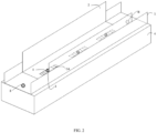
- FIG. 2 illustrates the connection of an earthquake resistant insert 2 to a runner 1 in greater detail.
- FIG. 2 depicts runner 1, the earthquake resistant insert 2, the first fixing member 3, the adjacent surface 4 and the elongate slots 5 of FIG. 1 , and also depicts the use of a third fixing member 8.
- the third fixing member 8 is used to fix the runner 1 in place with respect to the adjacent surface 4, differing from the first fixing member 3 in that the third fixing member 8 is not inserted through an elongate slot 5 in an earthquake resistant insert 2.
- the third fixing member 8 is not associated with the movement of the earthquake resistant insert 2 or the construction board 6 and provides firm fixation between the runner 1 and the adjacent surface 4.
- the third fixing member 8 are screws, although bolts, anchor blocks and other means of fixation, either separately or in combination, are also envisaged as alternatives.
- the third fixing member 8 may be located proximal to the end of the runners.
- the third fixing member 8 may be located at the ends of a first runner 9 and a second runner 11 as shown in FIG. 4 .
- Such an embodiment may be preferable as the third fixing member 8 may be prone to failure during an earthquake event by potentially lifting away or becoming detached from the adjacent surface.
- the third fixing member 8 may be regularly spaced along the length of the first runner 9 and the second runner 11. Such an embodiment may be preferable as it may ensure the first runner 9 and the second runner 11 are securely attached to an adjacent surface along substantially its length.
- the runner 1 is constructed from a material which can be described as textured, dimpled or ridged. In one other embodiment, the runner 1 is a metal channel. In one other embodiment, the runner 1 is a wood channel. In one other embodiment, the runner 1 is a plastic channel. Preferably the channels comprise U shaped cross sections. In yet another embodiment, the U shaped sections are metal.
- the earthquake resistant insert 2 is made from a metal.
- the earthquake resistant insert 2 is made of steel as it is a low cost material that could be easily worked with.
- steel earthquake resistant inserts 2 may have a smooth, low friction surface which can easily move within the runner 1, enabling the earthquake resistant construction system to resist damage during an earthquake event.
- the earthquake resistant insert 2 may comprise a textured surface.
- the textured surface may increase the strength of the earthquake resistant insert 2, providing the earthquake resistant wall construction with increased resistance to damage during an earthquake event.
- the textured surface may also provide the earthquake resistant insert 2 with additional rigidity such that the construction board 6 may be more easily affixed to the earthquake resistant insert 2 using the first fixing members 3.
- the textured surface may comprise any one of, or a combination of ribs, troughs, indents, undulations or dimples.
- the textures may be introduced onto the surface of the earthquake resistant insert 2 during the forming of the insert. In one other embodiment, the textures may be machined onto the surface of the earthquake resistant insert 2 after its formation.
- the elongate slot 5 lies substantially parallel to the longitudinal length of the runner 1. In one other embodiment, the elongate slot 5 may have a width greater than the diameter of the first fixing member 3. In one other embodiment, the elongate slot 5 may have a width at least 1 mm greater than the diameter of the first fixing member 3. In alternative embodiments, the elongate slot 5 may have a width of at least 3 mm, or at least 5 mm, greater than the diameter of the first fixing member 3. The use of an elongate slot 5 with a width greater than the diameter of the first fixing member 3 may be preferable as it may reduce any resistance to the movement of the earthquake resistant insert 2, and the attached construction board 6, during the earth movements associated with an earthquake event.
- the elongate slot 5 may have a length between 20 and 100 mm. In one other embodiment, the elongate slot 5 may have a length of 60 mm. In one other embodiment, the elongate slot 5 may have a length between 40 and 80 mm. The use of such lengths may be preferable as they allow the earthquake resistant wall construction sufficient mobility such that it may resist damage during the earth movements associated with an earthquake event. Preferably, the length of the elongate slot 5 may be chosen to correspond to the allowable inter-storey displacement of the building into which the earthquake resistant wall construction is inserted.
- the elongate slot 5 may comprise at least one resistant member 14 (shown in FIG. 5A to 5E ).
- the inclusion of at least one resistant member 14 in the elongate slot 5 may provide an additional level of control over the extent to which the earthquake resistant insert 2 may move relative to the runner 1 during any specific earthquake event.
- the response of the earthquake resistant wall construction may be tailored to be appropriate to the severity of any earthquake event.
- the resistant member 14 may be located substantially perpendicular to the long axis of the elongate slot 5.
- the resistant member 14 may comprise a strip of resistant material which extends across the elongate slot 5.
- the resistant member 14 may comprise a shaped edge of the elongate slot 5.
- the resistant member 14 may comprise at least one indent 15 along the length of the elongate slot 5.
- FIG. 3 depicts a partially assembled wall construction.
- a first runner 9 is connected to a floor surface 10, and a second runner 11 is connected to a ceiling surface 12.
- Earthquake resistant inserts 2 are located as illustrated in FIG. 2 in each of the first runner 9 and second runner 11, and each earthquake resistant insert 2 is connected to the construction board 6 via a plurality of second fixing members 7.
- the construction board 6 is held firmly between two surfaces 10 and 12, but may move longitudinally along the first and second runners 9 and 11 in response to the movements associated with an earthquake event.
- first runner 9 and second runner 11 are substantially opposite one another. Such an embodiment may be preferable as it may ease the construction of earthquake resistant walls and ceilings.
- the edge of the construction board 6 is located substantially outside the first runner 9 or the second runner 11. In such an embodiment, the construction board 6 may mask the first runner 9 and the second runner 11, such that the construction board 6 may abut adjacent surfaces. In this case, the aesthetics of the earthquake resistant wall construction may be improved, and the integration of the earthquake resistant insert 2 within an interior design plan be more easily achieved.
- the earthquake resistant wall construction comprises at least one strut 13 connected to the construction board 6.
- Such an embodiment may be preferable as it may allow the construction of larger walls, ceilings or other building elements using earthquake resistant wall construction connected by struts 13.
- an end of said strut 13 is located substantially with said first runner 9 or said second runner 11.
- the strut 13 may move freely with the construction board 6 in response to an earthquake event, potentially reducing any damage to the earthquake resistant wall construction.
- Such an embodiment may also be advantageous as the friction between the end of the strut 13 and the first runner 9 or second runner 11 may be controlled by the user via the choice of materials for both the strut 13 and the runners 9 and 11.
- the strut 13 may have no fixed connection to the runner.
- the strut 13 is a wall stud.
- the construction board 6 may be a gypsum panel with a high weight percentage of both glass fiber and starch.
- the construction board 6 may be a cementitious or wood based board, although the use of other materials is also envisaged.
- cementitious boards include, but are not limited to, those which comprise gypsum, Portland cement, calcium aluminate, magnesium oxychloride, magnesium phosphate, and mixtures thereof.
- the gypsum based boards may be of plasterboard type construction and may be faced with paper, glass fiber or other liners. Additionally, the gypsum based construction boards may be of a gypsum fiber, or similar, construction. In one other embodiment, the construction board 6 may comprise fiber cement. Such an embodiment of the invention may be preferable as the construction boards are readily available and may be formed into many shapes to provide walls, ceilings and other space dividing constructional elements in many forms.
- the construction board 6 may be reinforced. Such an embodiment of the invention may be preferable as the racking resistance of the construction board may be improved.
- the construction board 6 may comprise a polymeric binder and a plurality of fibres. Such a feature may be preferable as it may provide reinforcement to the construction board.
- said plurality of fibres may comprise glass fibres, synthetic polymer fibres or natural fibres, either separately or in combination.
- said polymeric binder and said plurality of fibres, in combination comprise greater than 1% by weight of the construction board 6.
- Such an embodiment of the invention may be preferable as it may increase the strength of the construction board 6.
- the polymeric binder may comprise greater than 1% by weight of the construction board 6.
- the fibres may comprise greater than 1% by weight of the construction board 6.
- the polymeric binder may comprise starch.
- the polymeric binder may comprise synthetic material not limiting to polyvinyl acetate.
- the construction board 6 may comprise a Habito (registered trade mark) board.
- FIG. 4 schematically illustrates an earthquake resistant, non-loadbearing wall 100.
- the construction board 6, held in place with earthquake resistant inserts 2 located inside the first runner 9 and the second runner 11 are connected with studs 13.
- the construction boards 6 which form the non-loadbearing wall 100 depicted in FIG. 4 may move together in response to an earthquake event, held in position relative to one another by the studs 13.
- the construction boards 6 may move together, longitudinally along the runner, as in this embodiment of the invention the construction boards 6 are located within the first runner 9 and second runner 11 via the use of earthquake resistant inserts 2 and first fixing members 3.
- a wall 100 with both sufficient stability to support items such as televisions and computer screens and sufficient mobility to resist damage during an earthquake is provided.
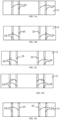
- FIG. 5A to FIG. 5E schematically illustrate various embodiments of the elongate slot 5 of the earthquake resistant insert 2.
- resistant members 14 are located generally perpendicularly to the long axis of the elongate slot 5 as shown in FIG. 5A . These resistant members 14 provide a resistance or hindrance to the movement of the first fixing member 3 within the elongate slot 5, such that the earthquake resistant insert 2 only moves relative to the runner 1 in response to large movements of the surrounding structure, such as those associated with an earthquake event.
- the resistant members 14 include a central indent 15, whereabouts the resistant member 14 is weakened such that it may break or deform if the movement of the earthquake resistant insert 2 relative to the runner 1 is caused by the earth movements associated with an earthquake event.
- the resistant members 14 include a central indent 15 in a direction towards the first fixing member 3, whereabouts the resistant member 14 is weakened such that it may break or deform if the movement of the earthquake resistant insert 2 relative to the runner 1 is caused by the earth movements associated with an earthquake event.
- the resistant members 14 include a central indent 15 in a direction opposite to the first fixing member 3, whereabouts the resistant member 14 is weakened such that it may break or deform if the movement of the earthquake resistant insert 2 relative to the runner 1 is caused by the earth movements associated with an earthquake event.
- the resistant members 14 include an indent 15 towards the edges of the resistant members 14, whereabouts the resistant member 14 is weakened such that it may break or deform if the movement of the earthquake resistant insert 2 relative to the runner 1 is caused by the earth movements associated with an earthquake event.
- the first fixing member 3 may move past the position of the resistant member 14, allowing the earthquake resistant insert 2 a greater range of motion within the runner 1.
- the resistant member 14 comprises steel. Additionally, in these embodiments, the resistant member 14 forms a continuous, single piece section, with the earthquake resistant insert 2.
- the earthquake resistant insert 2 was clamped to a concrete wall channel through the first fixing member 3 provided in the earthquake resistant insert 2.
- a gypsum board was attached to the earthquake resistant insert 2 by using two second fixing members 7. During the vibration, the earthquake resistant insert 2 allows the gypsum board to move in a uni-directional arrangement by allowing the first fixing member to move in the earthquake resistant insert 2.
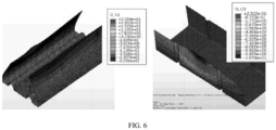
- Finite element analysis on the earthquake resistant insert 2 was defined by deflection analysis of the earthquake resistant insert 2 and the effect of the resistant member 14 on plastic deformation behavior of the earthquake resistant insert 2. Deflection analysis of the earthquake resistant insert 2 was performed to evaluate if the provision of resistant members 14 in the elongate slot 5 could reduce deflection in the earthquake resistant insert 2 during screwing. It was found that the installation of construction boards 6 onto the earthquake resistant insert 2 resulted in bending of the first and second legs of the earthquake resistant insert 2. Hence to reduce the bending, resistant members 14 were introduced into the elongate slot 5 of the earthquake resistant insert 2. Simulation results of an earthquake resistant insert 2 with resistant members 14 and without resistant members 14 is depicted in FIG. 6 . The inward displacement of the first and second legs of the earthquake resistant insert 2 was seen to be reduced in the presence of resistant members 14.
- the resistant members 14 work as an obstacle for the movement of the first fixing member 3.
- the following simulations were done to understand the effect of providing resistant members 14 with indent 15 at different locations along the length of the resistant member 14.
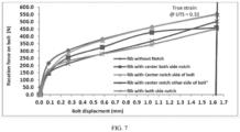
- the simulation results of resistant members 14 with the indent 15 at different locations have been shown in FIG. 7 .
- the results showed that the resistant member 14 with central indents 15 at both sides provides better results when compared to all other locations.
- the graph shows the simulated results of the force vs displacement for all the different locations of the indent 15.
- FIG. 8 a flowchart for a method 200 of constructing an earthquake resistant wall is illustrated.
- the earthquake resistant wall of FIG. 3 and FIG. 4 may be formed by implementing steps 210 to 260 of the method 200.
- it may also be contemplated to implement the method 200 with other suitable tools without deviating from the scope of the present disclosure.
- the first runner 9 and second runner 11 are provided adjacent to a surface.
- the first runner 9 and second runner 11 are provided adjacent to a wall and a ceiling surface, respectively.
- the first runner 9 and second runner 11 may be provided opposite to each other in a horizontal plane.
- the first runner 9 and second runner 11 are fixed to the adjacent surface using a third fixing member.
- one or more studs are slid along the length of the first runner 9 and second runner 11 by placing one end of the stud into the first runner 9 and the other end of the stud into the second runner 11.
- the number of stud depends on the length of the construction wall.
- an earthquake resistant insert 2 is placed between the studs in the first runner 9 and the second runner 11.
- the number of earthquake resistant insert 2 depends on the number of studs placed in the runners. In one other embodiment, the earthquake resistant inserts 2 alternate with the studs in the runners.
- the earthquake resistant insert 2 is fixed to the first runner 9 and second runner 11 through a first fixing member 3.
- a construction board 6 is attached on either side of the earthquake resistant insert 2 via at least one second fixing member 7.
- the construction boards 6 are not held in a fixed position relative to the first runner 9 and second runner 11. In one other embodiment, the construction boards 6 move longitudinally along the length of the first runner 9 and second runner 11 concomitant with the movement of the earthquake resistant insert 2 during an earthquake event.
- the earthquake resistant wall was constructed as per the method of the current invention.
- the earthquake resistant wall comprises earthquake resistant inserts fixed in the runners and construction boards fixed to the earthquake resistant inserts.
- the tested wall was approximately 2.4m tall and 4.8m long. This wall was installed over a concrete reaction beam of dimension 0.2 ⁇ 0.2 ⁇ 2.5m. A loading beam/spreader beam was provided on top of the wall, to allow for application of uniform shear. This spreader beam was made of two ISMC 150 channels [5] at 100 mm clear spacing, between which concrete blocks were fixed in order to simulate conditions similar to actual site conditions. The top track of wall panel was attached to the spreader beam and the bottom track to the reaction beam by 8 mm ⁇ Hilti bolts (Sleeve Anchor HLC 8 ⁇ 40/10).
- the Tee bracket was connected to the web of an ISMB 250 [5] beam at the top of the loading frame, which in turn was connected to the face of the vertical members of the reaction frame.
- a gap of 10 mm was ensured between the board and the beams at top and bottom of the loading frame.
- the spreader beam was connected to the actuator.
- the in-plane shear load was applied through spreader beam using the programmable servo-hydraulic actuator (MTS System Corporation).
- the load carrying capacity of the actuator was 350 kN with the displacement range of +/- 250 mm.
- Linear Variable differential transformers were used to measure the vertical and horizontal displacements. All the LVDTs were connected to a data-logger for automatic data acquisition at a predefined rate.
- ASTM standards (ASTM E564 [6] for monotonic tests & ASTM E 2126 [7] for cyclic tests) for seismic testing of wall elements was followed for this test.
- This standard covers three loading protocols for the evaluation of the shear stiffness, shear strength, and ductility of the vertical elements of lateral force resisting systems, including applicable shear connections and hold-down connections, under quasi-static cyclic (reversed) load conditions. Earthquakes being random vibrations, there was no unique cyclic displacement or loading history which can perfectly replicate the actual loading. These loading protocols were intended to produce data that sufficiently describe elastic and inelastic cyclic properties; and the typical failure mode that was expected in earthquake loading.
- FIG. 9 provides the graphical representation of the seismic testing results.
- the results of a wall made of standard plasterboard, single layer; standard plasterboard, single layer with earthquake resistant inserts; and Habito board, single layer are provided. The results are also tabulated in Table. 1
- Table 1 Results of Seismic Testing of Construction Boards - Full Scale Set-up S ample/Parameters Standard plasterboard, single layer Standard plasterboard, single layer with earthquake resistant insert Habito board, single layer Force (kN) 10 8 20 Displacement (mm) 32 80 37
- FIG. 9 further illustrates a horizontal line on the plot at ⁇ 6kN indicating the minimum force capacity for the test wall (2.4m ⁇ 4.8m, weight ⁇ 250kg) to pass the force requirement of all the major standard building code requirements such as.
- the displacement requirement was more varied for the different building codes, i.e. for the Eurocode, the required displacement capacity was 24-36mm, and for the American code, ASCE the requirement was 36-60mm.
- ASCE the requirement was 36-60mm.
- the strength of the wall should exceed 6kN and the displacement capacity should exceed 60mm.
- Standard plasterboard wall are capable of passing the force requirement of all major building codes reviewed. However it does not have the flexibility to obtain the full displacement requirement.
- the wall with Habito boards was found to have higher force capacity compared to the standard wall, but there was no significant increase in displacement capacity.
- a Habito board with earthquake resistant insert which will have high strength and required flexibility to maintain load capacity of the wall can be used.
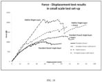
- FIG. 10 illustrates force-displacement test results in a lab scale test set-up.
- the Habito board system with earthquake resistant inserts withstands higher displacement compared to a standard board (90mm vs. 64mm) combined with high strength (1900 N vs. 1300N) and thus presented a "best solution" with optimal value of strength and flexibility.
- Table 2 Results of Seismic Testing of Construction Boards - Lab Scale Set-up Sample/ Parameters Standard plasterboard, single layer Standard plasterboard, single layer with earthquake resistant insert Habito board, single layer Standard plasterboard, single layer with earthquake resistant insert Force (N) 1000 1300 2150 1900+* Displacement (mm) 42 64 56 90+* *The test was stopped before achieving full system failure, due to limitations of the test set-up
- the terms “comprises,” “comprising,” “includes,” “including,” “has,” “having” or any other variation thereof, are intended to cover a non-exclusive inclusion.
- a method, article, or apparatus that comprises a list of features is not necessarily limited only to those features but may include other features not expressly listed or inherent to such method, article, or apparatus.
- “or” refers to an inclusive-or and not to an exclusive-or. For example, a condition A or B is satisfied by any one of the following: A is true (or present) and B is false (or not present), A is false (or not present) and B is true (or present), and both A and B are true (or present).
Landscapes
- Engineering & Computer Science (AREA)
- Architecture (AREA)
- Business, Economics & Management (AREA)
- Emergency Management (AREA)
- Environmental & Geological Engineering (AREA)
- Civil Engineering (AREA)
- Structural Engineering (AREA)
- Physics & Mathematics (AREA)
- Electromagnetism (AREA)
- Load-Bearing And Curtain Walls (AREA)
- Finishing Walls (AREA)
- Buildings Adapted To Withstand Abnormal External Influences (AREA)
Claims (18)
- Construction de mur antisismique, comprenant ;un premier canal (1) ;un second canal (11) ; etau moins un insert antisismique (2) prévu à l'intérieur du premier canal (1) ou du second canal (11) ;l'insert antisismique (2) comprenant au moins une fente allongée (5) et étant maintenu en communication avec le premier canal (1) ou le second canal (11) par l'intermédiaire d'au moins un premier élément de fixation (3) qui passe à travers la fente allongée (5), etl'insert antisismique (2) étant relié à une plaque de construction (6) de part et d'autre de l'insert antisismique (2) par l'intermédiaire d'au moins un deuxième élément de fixation (7), etla construction de mur comprenant en outre au moins une entretoise de mur (13) reliée à la plaque de construction (6), avec une extrémité de ladite entretoise située sensiblement à l'intérieur dudit premier canal (1) ou dudit second canal (11).
- Construction de mur antisismique selon la revendication 1, dans laquelle le premier canal (1) est prévu sur un plancher et le second canal (11) est prévu sur un plafond.
- Construction de mur antisismique selon l'une quelconque revendication précédente, dans laquelle l'axe long de la fente allongée (5) est sensiblement parallèle à la longueur longitudinale du premier canal (1) ou du second canal (11) et la fente allongée (5) ayant une largeur supérieure au diamètre du premier élément de fixation (3).
- Construction de mur antisismique selon l'une quelconque revendication précédente, dans laquelle l'insert antisismique (2) a une forme qui se conforme à la forme du canal (1, 11) correspondant et est situé sensiblement à l'intérieur de premier canal (1) ou du second canal (11).
- Construction de mur antisismique selon l'une quelconque revendication précédente, dans laquelle l'insert antisismique (2) s'étend au-dessus du premier canal et du second canal (1, 11).
- Construction de mur antisismique selon l'une quelconque revendication précédente, dans laquelle la fente allongée (5) comprend au moins un élément résistant (14) perpendiculaire à la longueur du canal (1, 11).
- Construction de mur antisismique selon l'une quelconque revendication précédente, comprenant en outre au moins une entretoise (13) reliée à la plaque de construction (6), l'entretoise étant située sensiblement à l'intérieur du premier canal (1) ou du second canal (11).
- Construction de mur antisismique selon la revendication 7, dans laquelle l'au moins une entretoise (13) comprend un goujon de mur.
- Construction de mur antisismique selon l'une quelconque revendication précédente, comprenant en outre au moins un troisième élément de fixation (8) qui relie le premier canal (1) ou le second canal (11) à une surface adjacente.
- Construction de mur antisismique selon l'une quelconque revendication précédente, dans laquelle la plaque de construction (6) comprend du gypse ou du ciment ou du fibrociment.
- Construction de mur antisismique selon l'une quelconque revendication précédente, dans laquelle le premier canal (1) et le second canal (11) peuvent être espacés dans un plan horizontal.
- Construction de mur antisismique selon l'une quelconque des revendications 1 à 11, comprenant un insert antisismique (2), l'insert antisismique (2) comprenant :une première patte ;une seconde patte ; etune base,les première et seconde pattes s'étendant perpendiculairement à partir de la base,la base comprenant en outre au moins une fente allongée (5) pour recevoir au moins un premier élément de fixation (3),la base étant conçue pour être placée à l'intérieur d'un canal (1, 11) d'une construction de mur, et la première patte et la seconde patte étant conçues pour être reliées à une plaque de construction (6) de part et d'autre à l'aide d'au moins un deuxième élément de fixation (7).
- Construction de mur antisismique selon la revendication 12, dans laquelle l'axe long de la fente allongée (5) est sensiblement parallèle à la longueur longitudinale du canal (1, 11) et la fente allongée (5) ayant une largeur supérieure au diamètre du premier élément de fixation (3).
- Construction de mur antisismique selon la revendication 12, dans laquelle la fente allongée (5) comprend en outre au moins un élément résistant (14) perpendiculaire à la longueur du premier canal (1) ou du second canal (11).
- Construction de mur antisismique selon la revendication 14, dans laquelle l'élément résistant (14) a au moins une entaille (15) le long de sa longueur.
- Construction de mur antisismique selon la revendication 12, dans laquelle elle comprend une surface texturée.
- Procédé de construction d'une construction de mur antisismique selon l'une quelconque des revendications 1 à 11, comprenant :la fourniture d'un premier canal (1) et d'un second canal (11) ;la fixation des premier et second canaux (1, 11) à une surface adjacente à l'aide d'au moins un troisième élément de fixation (8) ;le glissement d'un ou de plusieurs goujons (13) sur les canaux en plaçant une extrémité du goujon (13) dans le premier canal (1) et l'autre extrémité du goujon (13) dans le second canal (11) ;le placement d'un insert antisismique (2) entre les goujons (13) dans le premier canal (1) et/ou le second canal (11), l'insert antisismique comprenant une première patte, une seconde patte et une base, avec les première et seconde pattes s'étendant perpendiculairement à partir de la base, et la base comprenant en outre au moins une fente allongée (5) pour recevoir au moins un premier élément de fixation (3),la fixation de l'insert antisismique (2) sur les premier et second canaux (1, 11) à travers le premier élément de fixation (3) ; etla fixation d'une plaque de construction (6) de part et d'autre de l'insert antisismique (2) par l'intermédiaire d'au moins un deuxième élément de fixation (7).
- Procédé selon la revendication 17, dans lequel les plaques de construction (6) ne sont pas maintenus en position fixe par rapport aux premier et second canaux (1, 11) et se déplacent longitudinalement le long de la longueur des premier et second canaux (1, 11) en concomitance avec le mouvement de l'insert antisismique (2) pendant un tremblement de terre.
Applications Claiming Priority (2)
| Application Number | Priority Date | Filing Date | Title |
|---|---|---|---|
| IN5928CH2015 | 2015-11-02 | ||
| PCT/IN2016/050366 WO2017077548A1 (fr) | 2015-11-02 | 2016-10-27 | Élément de construction antisismique |
Publications (4)
| Publication Number | Publication Date |
|---|---|
| EP3371393A1 EP3371393A1 (fr) | 2018-09-12 |
| EP3371393A4 EP3371393A4 (fr) | 2019-08-21 |
| EP3371393B1 true EP3371393B1 (fr) | 2023-07-19 |
| EP3371393C0 EP3371393C0 (fr) | 2023-07-19 |
Family
ID=58661712
Family Applications (1)
| Application Number | Title | Priority Date | Filing Date |
|---|---|---|---|
| EP16861735.5A Active EP3371393B1 (fr) | 2015-11-02 | 2016-10-27 | Construction de murs antisismiques |
Country Status (11)
| Country | Link |
|---|---|
| US (1) | US10669733B2 (fr) |
| EP (1) | EP3371393B1 (fr) |
| JP (1) | JP6989498B2 (fr) |
| AU (1) | AU2016350070B2 (fr) |
| CA (1) | CA3004003C (fr) |
| CL (1) | CL2018001155A1 (fr) |
| ES (1) | ES2955470T3 (fr) |
| MX (1) | MX2018005249A (fr) |
| MY (1) | MY191123A (fr) |
| TW (1) | TWI718196B (fr) |
| WO (1) | WO2017077548A1 (fr) |
Families Citing this family (3)
| Publication number | Priority date | Publication date | Assignee | Title |
|---|---|---|---|---|
| KR102251690B1 (ko) * | 2019-12-03 | 2021-05-13 | 주식회사 케이씨씨 | 런너 및 이를 구비한 벽체시스템 |
| CN112695917B (zh) * | 2020-12-23 | 2022-04-19 | 湖北正浩建设集团有限公司 | 钢混结构建筑的剪力墙结构及其施工方法 |
| US20240125137A1 (en) * | 2022-10-17 | 2024-04-18 | Luis Miguel Bozzo Rotondo | Buckling Delayed Shear Link |
Family Cites Families (21)
| Publication number | Priority date | Publication date | Assignee | Title |
|---|---|---|---|---|
| US2683927A (en) * | 1950-09-11 | 1954-07-20 | Smith Corp A O | Method of locating and holding metal members in place |
| US5113631A (en) * | 1990-03-15 | 1992-05-19 | Digirolamo Edward R | Structural system for supporting a building utilizing light weight steel framing for walls and hollow core concrete slabs for floors and method of making same |
| JPH10292597A (ja) * | 1997-04-17 | 1998-11-04 | Shuichi Koseki | 建築躯体における耐震性鋼製壁下地装置 |
| US5913788A (en) * | 1997-08-01 | 1999-06-22 | Herren; Thomas R. | Fire blocking and seismic resistant wall structure |
| JP2002070239A (ja) * | 2000-08-25 | 2002-03-08 | Yoshino Gypsum Co Ltd | 耐力壁に適する石膏系建材 |
| US6612087B2 (en) * | 2000-11-29 | 2003-09-02 | The Steel Network, Inc. | Building member connector allowing bi-directional relative movement |
| US8387321B2 (en) * | 2002-03-12 | 2013-03-05 | The Steel Network, Inc. | Connector for connecting building components |
| US7533508B1 (en) * | 2002-03-12 | 2009-05-19 | The Steel Network, Inc. | Connector for connecting building components |
| FR2863284B1 (fr) * | 2003-12-05 | 2007-11-23 | Placoplatre Sa | Dispositif pour le montage parasismique d'une cloison |
| US20060032157A1 (en) * | 2004-07-30 | 2006-02-16 | Mareck Baryla | Seismic wall system |
| US8769887B2 (en) * | 2006-06-15 | 2014-07-08 | Ray A. Proffitt, Jr. | Hold down clip and wall system |
| US8413394B2 (en) * | 2007-08-06 | 2013-04-09 | California Expanded Metal Products Company | Two-piece track system |
| US8499512B2 (en) * | 2008-01-16 | 2013-08-06 | California Expanded Metal Products Company | Exterior wall construction product |
| US8555566B2 (en) * | 2007-08-06 | 2013-10-15 | California Expanded Metal Products Company | Two-piece track system |
| JP2010071021A (ja) * | 2008-09-22 | 2010-04-02 | Takenaka Komuten Co Ltd | 軽量鉄骨間仕切り壁とその構築方法 |
| BR112012028026A2 (pt) * | 2010-05-05 | 2017-03-28 | Eberhard Von Huene & Ass Inc | sietema de painel de parede movível e desmontável |
| JP5399361B2 (ja) * | 2010-11-05 | 2014-01-29 | 株式会社アールシーコア | 間仕切り壁の取付け構造 |
| CN102108752B (zh) * | 2011-01-14 | 2012-05-23 | 北京交通大学 | 消能减震型密肋复合墙板及其制作方法 |
| JP2013181285A (ja) * | 2012-02-29 | 2013-09-12 | Uchiyama Sangyo:Kk | 間仕切り壁の耐震構造 |
| MX357368B (es) | 2012-08-24 | 2018-07-06 | Allsteel Inc | Sistema de pared modular. |
| CN104989013B (zh) * | 2015-07-10 | 2017-11-17 | 浙江大学宁波理工学院 | 抗震框架剪力墙及其施工方法 |
-
2016
- 2016-10-27 AU AU2016350070A patent/AU2016350070B2/en active Active
- 2016-10-27 CA CA3004003A patent/CA3004003C/fr active Active
- 2016-10-27 ES ES16861735T patent/ES2955470T3/es active Active
- 2016-10-27 MX MX2018005249A patent/MX2018005249A/es unknown
- 2016-10-27 US US15/772,687 patent/US10669733B2/en active Active
- 2016-10-27 JP JP2018522634A patent/JP6989498B2/ja active Active
- 2016-10-27 EP EP16861735.5A patent/EP3371393B1/fr active Active
- 2016-10-27 WO PCT/IN2016/050366 patent/WO2017077548A1/fr active Application Filing
- 2016-10-27 MY MYPI2018701711A patent/MY191123A/en unknown
- 2016-10-28 TW TW105135018A patent/TWI718196B/zh active
-
2018
- 2018-04-30 CL CL2018001155A patent/CL2018001155A1/es unknown
Also Published As
| Publication number | Publication date |
|---|---|
| JP2018532917A (ja) | 2018-11-08 |
| JP6989498B2 (ja) | 2022-01-05 |
| CL2018001155A1 (es) | 2018-11-05 |
| TW201718990A (zh) | 2017-06-01 |
| MX2018005249A (es) | 2018-08-01 |
| CA3004003C (fr) | 2022-12-06 |
| US10669733B2 (en) | 2020-06-02 |
| US20190161990A1 (en) | 2019-05-30 |
| AU2016350070B2 (en) | 2021-09-02 |
| MY191123A (en) | 2022-05-30 |
| EP3371393A4 (fr) | 2019-08-21 |
| EP3371393A1 (fr) | 2018-09-12 |
| EP3371393C0 (fr) | 2023-07-19 |
| WO2017077548A1 (fr) | 2017-05-11 |
| ES2955470T3 (es) | 2023-12-01 |
| CA3004003A1 (fr) | 2017-05-11 |
| TWI718196B (zh) | 2021-02-11 |
| AU2016350070A1 (en) | 2018-05-10 |
Similar Documents
| Publication | Publication Date | Title |
|---|---|---|
| Loss et al. | Simple cross-laminated timber shear connections with spatially arranged screws | |
| Shams et al. | Experimental investigations on textile-reinforced concrete (TRC) sandwich sections | |
| EP3371393B1 (fr) | Construction de murs antisismiques | |
| Karabulut et al. | Experimental and analytical studies on different configurations of cold-formed steel structures | |
| Elawady et al. | Seismic behaviour of high-rise buildings with transfer floors | |
| Sen et al. | Displacement-based seismic design of flat slab-shear wall buildings | |
| Monteiro et al. | Seismic characterization and Evaluation of an Old Masonry building | |
| Hsu et al. | Behavior of composite beams with cold-formed steel joists and concrete slab | |
| Parisi et al. | Review of experimental research on progressive collapse of RC structures | |
| Pundkar et al. | Influence of steel plate shear wall on multistorey steel building | |
| Eid et al. | Numerical simulation of ultra‐lightweight concrete encased cold‐formed steel structures | |
| Çankaya | Dynamic behavior of reinforced concrete frames with infill walls | |
| EP4111009A1 (fr) | Goujon de guidage et structure de paroi de séparation correspondante | |
| Getz et al. | Static and cyclic racking performance of autoclaved aerated concrete cladding panels | |
| Hiwase et al. | Comparison of Seismic Analysis and Static Analysis of Residential Building Using Staad. Pro | |
| Danila | Seismic isolation systems for buildings subjected to Vrancea earthquakes | |
| Segura et al. | Flexural compression capacity of thin reinforced concrete structural walls | |
| Huq et al. | Influence of mechanical properties of high-strength steel on deformation capacity of reinforced concrete walls | |
| Lu et al. | Experimental study on the hysteretic performance of a self-centering frame infilled with a bamboo wall | |
| Kania et al. | Research on crack formation in gypsum partitions with doorway by means of FEM and fracture mechanics | |
| Derveni et al. | Impact of Fastener Spacing on the Behavior of Cold-Formed Steel Shear Walls Sheathed with Fiber Cement Board | |
| Farazmand et al. | Nonlinear behavior of stiffened steel plate shear walls | |
| Myers | Strengthening unreinforced masonry structures using externally bonded fiber reinforced polymer systems: An overview of the American concrete institute 440.7 R design approach | |
| Szczepański et al. | Timber frame houses resistant to dynamic loads-seismic analysis | |
| Pehlivan | Experimental investigation of structural systems made of sheathed cold-formed steel wall panels |
Legal Events
| Date | Code | Title | Description |
|---|---|---|---|
| STAA | Information on the status of an ep patent application or granted ep patent |
Free format text: STATUS: THE INTERNATIONAL PUBLICATION HAS BEEN MADE |
|
| PUAI | Public reference made under article 153(3) epc to a published international application that has entered the european phase |
Free format text: ORIGINAL CODE: 0009012 |
|
| STAA | Information on the status of an ep patent application or granted ep patent |
Free format text: STATUS: REQUEST FOR EXAMINATION WAS MADE |
|
| 17P | Request for examination filed |
Effective date: 20180604 |
|
| AK | Designated contracting states |
Kind code of ref document: A1 Designated state(s): AL AT BE BG CH CY CZ DE DK EE ES FI FR GB GR HR HU IE IS IT LI LT LU LV MC MK MT NL NO PL PT RO RS SE SI SK SM TR |
|
| AX | Request for extension of the european patent |
Extension state: BA ME |
|
| DAV | Request for validation of the european patent (deleted) | ||
| DAX | Request for extension of the european patent (deleted) | ||
| A4 | Supplementary search report drawn up and despatched |
Effective date: 20190719 |
|
| RIC1 | Information provided on ipc code assigned before grant |
Ipc: E04H 9/02 20060101AFI20190715BHEP |
|
| RAP1 | Party data changed (applicant data changed or rights of an application transferred) |
Owner name: SAINT-GOBAIN PLACO |
|
| STAA | Information on the status of an ep patent application or granted ep patent |
Free format text: STATUS: EXAMINATION IS IN PROGRESS |
|
| STAA | Information on the status of an ep patent application or granted ep patent |
Free format text: STATUS: EXAMINATION IS IN PROGRESS |
|
| 17Q | First examination report despatched |
Effective date: 20201023 |
|
| STAA | Information on the status of an ep patent application or granted ep patent |
Free format text: STATUS: EXAMINATION IS IN PROGRESS |
|
| GRAP | Despatch of communication of intention to grant a patent |
Free format text: ORIGINAL CODE: EPIDOSNIGR1 |
|
| STAA | Information on the status of an ep patent application or granted ep patent |
Free format text: STATUS: GRANT OF PATENT IS INTENDED |
|
| INTG | Intention to grant announced |
Effective date: 20230207 |
|
| GRAS | Grant fee paid |
Free format text: ORIGINAL CODE: EPIDOSNIGR3 |
|
| GRAA | (expected) grant |
Free format text: ORIGINAL CODE: 0009210 |
|
| STAA | Information on the status of an ep patent application or granted ep patent |
Free format text: STATUS: THE PATENT HAS BEEN GRANTED |
|
| AK | Designated contracting states |
Kind code of ref document: B1 Designated state(s): AL AT BE BG CH CY CZ DE DK EE ES FI FR GB GR HR HU IE IS IT LI LT LU LV MC MK MT NL NO PL PT RO RS SE SI SK SM TR |
|
| REG | Reference to a national code |
Ref country code: GB Ref legal event code: FG4D |
|
| REG | Reference to a national code |
Ref country code: CH Ref legal event code: EP |
|
| REG | Reference to a national code |
Ref country code: DE Ref legal event code: R096 Ref document number: 602016081228 Country of ref document: DE |
|
| REG | Reference to a national code |
Ref country code: IE Ref legal event code: FG4D |
|
| REG | Reference to a national code |
Ref country code: RO Ref legal event code: EPE |
|
| U01 | Request for unitary effect filed |
Effective date: 20230725 |
|
| U07 | Unitary effect registered |
Designated state(s): AT BE BG DE DK EE FI FR IT LT LU LV MT NL PT SE SI Effective date: 20230731 |
|
| REG | Reference to a national code |
Ref country code: NO Ref legal event code: T2 Effective date: 20230719 |
|
| PGFP | Annual fee paid to national office [announced via postgrant information from national office to epo] |
Ref country code: RO Payment date: 20230925 Year of fee payment: 8 |
|
| REG | Reference to a national code |
Ref country code: LT Ref legal event code: MG9D |
|
| PGFP | Annual fee paid to national office [announced via postgrant information from national office to epo] |
Ref country code: GR Payment date: 20230913 Year of fee payment: 8 |
|
| REG | Reference to a national code |
Ref country code: GR Ref legal event code: EP Ref document number: 20230401581 Country of ref document: GR Effective date: 20231113 |
|
| REG | Reference to a national code |
Ref country code: ES Ref legal event code: FG2A Ref document number: 2955470 Country of ref document: ES Kind code of ref document: T3 Effective date: 20231201 |
|
| U20 | Renewal fee paid [unitary effect] |
Year of fee payment: 8 Effective date: 20231110 |
|
| PGFP | Annual fee paid to national office [announced via postgrant information from national office to epo] |
Ref country code: ES Payment date: 20231107 Year of fee payment: 8 |
|
| PG25 | Lapsed in a contracting state [announced via postgrant information from national office to epo] |
Ref country code: IS Free format text: LAPSE BECAUSE OF FAILURE TO SUBMIT A TRANSLATION OF THE DESCRIPTION OR TO PAY THE FEE WITHIN THE PRESCRIBED TIME-LIMIT Effective date: 20231119 |
|
| PG25 | Lapsed in a contracting state [announced via postgrant information from national office to epo] |
Ref country code: RS Free format text: LAPSE BECAUSE OF FAILURE TO SUBMIT A TRANSLATION OF THE DESCRIPTION OR TO PAY THE FEE WITHIN THE PRESCRIBED TIME-LIMIT Effective date: 20230719 Ref country code: IS Free format text: LAPSE BECAUSE OF FAILURE TO SUBMIT A TRANSLATION OF THE DESCRIPTION OR TO PAY THE FEE WITHIN THE PRESCRIBED TIME-LIMIT Effective date: 20231119 Ref country code: HR Free format text: LAPSE BECAUSE OF FAILURE TO SUBMIT A TRANSLATION OF THE DESCRIPTION OR TO PAY THE FEE WITHIN THE PRESCRIBED TIME-LIMIT Effective date: 20230719 |
|
| PGFP | Annual fee paid to national office [announced via postgrant information from national office to epo] |
Ref country code: TR Payment date: 20231009 Year of fee payment: 8 Ref country code: NO Payment date: 20231010 Year of fee payment: 8 |
|
| PG25 | Lapsed in a contracting state [announced via postgrant information from national office to epo] |
Ref country code: PL Free format text: LAPSE BECAUSE OF FAILURE TO SUBMIT A TRANSLATION OF THE DESCRIPTION OR TO PAY THE FEE WITHIN THE PRESCRIBED TIME-LIMIT Effective date: 20230719 |
|
| REG | Reference to a national code |
Ref country code: DE Ref legal event code: R097 Ref document number: 602016081228 Country of ref document: DE |
|
| PG25 | Lapsed in a contracting state [announced via postgrant information from national office to epo] |
Ref country code: SM Free format text: LAPSE BECAUSE OF FAILURE TO SUBMIT A TRANSLATION OF THE DESCRIPTION OR TO PAY THE FEE WITHIN THE PRESCRIBED TIME-LIMIT Effective date: 20230719 Ref country code: CZ Free format text: LAPSE BECAUSE OF FAILURE TO SUBMIT A TRANSLATION OF THE DESCRIPTION OR TO PAY THE FEE WITHIN THE PRESCRIBED TIME-LIMIT Effective date: 20230719 Ref country code: SK Free format text: LAPSE BECAUSE OF FAILURE TO SUBMIT A TRANSLATION OF THE DESCRIPTION OR TO PAY THE FEE WITHIN THE PRESCRIBED TIME-LIMIT Effective date: 20230719 |
|
| PGFP | Annual fee paid to national office [announced via postgrant information from national office to epo] |
Ref country code: CH Payment date: 20240126 Year of fee payment: 8 |
|
| PLBE | No opposition filed within time limit |
Free format text: ORIGINAL CODE: 0009261 |
|
| STAA | Information on the status of an ep patent application or granted ep patent |
Free format text: STATUS: NO OPPOSITION FILED WITHIN TIME LIMIT |
|
| PG25 | Lapsed in a contracting state [announced via postgrant information from national office to epo] |
Ref country code: MC Free format text: LAPSE BECAUSE OF FAILURE TO SUBMIT A TRANSLATION OF THE DESCRIPTION OR TO PAY THE FEE WITHIN THE PRESCRIBED TIME-LIMIT Effective date: 20230719 |
|
| 26N | No opposition filed |
Effective date: 20240422 |
|
| GBPC | Gb: european patent ceased through non-payment of renewal fee |
Effective date: 20231027 |
|
| PG25 | Lapsed in a contracting state [announced via postgrant information from national office to epo] |
Ref country code: GB Free format text: LAPSE BECAUSE OF NON-PAYMENT OF DUE FEES Effective date: 20231027 |
|
| PG25 | Lapsed in a contracting state [announced via postgrant information from national office to epo] |
Ref country code: GB Free format text: LAPSE BECAUSE OF NON-PAYMENT OF DUE FEES Effective date: 20231027 |