EP3370985B1 - Vehicle comprising energy harvesting suspension system, and method for converting mechanical energy into electrical energy - Google Patents
Vehicle comprising energy harvesting suspension system, and method for converting mechanical energy into electrical energy Download PDFInfo
- Publication number
- EP3370985B1 EP3370985B1 EP16862599.4A EP16862599A EP3370985B1 EP 3370985 B1 EP3370985 B1 EP 3370985B1 EP 16862599 A EP16862599 A EP 16862599A EP 3370985 B1 EP3370985 B1 EP 3370985B1
- Authority
- EP
- European Patent Office
- Prior art keywords
- fluid
- vehicle
- outlet hose
- displacement pump
- cylinder
- Prior art date
- Legal status (The legal status is an assumption and is not a legal conclusion. Google has not performed a legal analysis and makes no representation as to the accuracy of the status listed.)
- Active
Links
- 239000000725 suspension Substances 0.000 title claims description 14
- 238000000034 method Methods 0.000 title claims description 5
- 238000003306 harvesting Methods 0.000 title description 8
- 239000012530 fluid Substances 0.000 claims description 79
- 238000006073 displacement reaction Methods 0.000 claims description 24
- 230000006835 compression Effects 0.000 claims description 8
- 238000007906 compression Methods 0.000 claims description 8
- 239000003990 capacitor Substances 0.000 claims description 5
- 238000007599 discharging Methods 0.000 claims description 3
- 238000005507 spraying Methods 0.000 description 3
- XLYOFNOQVPJJNP-UHFFFAOYSA-N water Substances O XLYOFNOQVPJJNP-UHFFFAOYSA-N 0.000 description 3
- 239000006096 absorbing agent Substances 0.000 description 2
- 238000004891 communication Methods 0.000 description 2
- 230000035939 shock Effects 0.000 description 2
- 230000000694 effects Effects 0.000 description 1
- 239000003344 environmental pollutant Substances 0.000 description 1
- 239000000446 fuel Substances 0.000 description 1
- 239000007789 gas Substances 0.000 description 1
- 230000005484 gravity Effects 0.000 description 1
- 229910001385 heavy metal Inorganic materials 0.000 description 1
- 230000010355 oscillation Effects 0.000 description 1
- 231100000719 pollutant Toxicity 0.000 description 1
- 238000010248 power generation Methods 0.000 description 1
- 238000009987 spinning Methods 0.000 description 1
Images


Classifications
-
- B—PERFORMING OPERATIONS; TRANSPORTING
- B60—VEHICLES IN GENERAL
- B60G—VEHICLE SUSPENSION ARRANGEMENTS
- B60G13/00—Resilient suspensions characterised by arrangement, location or type of vibration dampers
- B60G13/14—Resilient suspensions characterised by arrangement, location or type of vibration dampers having dampers accumulating utilisable energy, e.g. compressing air
-
- B—PERFORMING OPERATIONS; TRANSPORTING
- B60—VEHICLES IN GENERAL
- B60K—ARRANGEMENT OR MOUNTING OF PROPULSION UNITS OR OF TRANSMISSIONS IN VEHICLES; ARRANGEMENT OR MOUNTING OF PLURAL DIVERSE PRIME-MOVERS IN VEHICLES; AUXILIARY DRIVES FOR VEHICLES; INSTRUMENTATION OR DASHBOARDS FOR VEHICLES; ARRANGEMENTS IN CONNECTION WITH COOLING, AIR INTAKE, GAS EXHAUST OR FUEL SUPPLY OF PROPULSION UNITS IN VEHICLES
- B60K25/00—Auxiliary drives
- B60K25/10—Auxiliary drives directly from oscillating movements due to vehicle running motion, e.g. suspension movement
-
- F—MECHANICAL ENGINEERING; LIGHTING; HEATING; WEAPONS; BLASTING
- F03—MACHINES OR ENGINES FOR LIQUIDS; WIND, SPRING, OR WEIGHT MOTORS; PRODUCING MECHANICAL POWER OR A REACTIVE PROPULSIVE THRUST, NOT OTHERWISE PROVIDED FOR
- F03B—MACHINES OR ENGINES FOR LIQUIDS
- F03B1/00—Engines of impulse type, i.e. turbines with jets of high-velocity liquid impinging on blades or like rotors, e.g. Pelton wheels; Parts or details peculiar thereto
-
- F—MECHANICAL ENGINEERING; LIGHTING; HEATING; WEAPONS; BLASTING
- F03—MACHINES OR ENGINES FOR LIQUIDS; WIND, SPRING, OR WEIGHT MOTORS; PRODUCING MECHANICAL POWER OR A REACTIVE PROPULSIVE THRUST, NOT OTHERWISE PROVIDED FOR
- F03B—MACHINES OR ENGINES FOR LIQUIDS
- F03B13/00—Adaptations of machines or engines for special use; Combinations of machines or engines with driving or driven apparatus; Power stations or aggregates
-
- F—MECHANICAL ENGINEERING; LIGHTING; HEATING; WEAPONS; BLASTING
- F03—MACHINES OR ENGINES FOR LIQUIDS; WIND, SPRING, OR WEIGHT MOTORS; PRODUCING MECHANICAL POWER OR A REACTIVE PROPULSIVE THRUST, NOT OTHERWISE PROVIDED FOR
- F03G—SPRING, WEIGHT, INERTIA OR LIKE MOTORS; MECHANICAL-POWER PRODUCING DEVICES OR MECHANISMS, NOT OTHERWISE PROVIDED FOR OR USING ENERGY SOURCES NOT OTHERWISE PROVIDED FOR
- F03G7/00—Mechanical-power-producing mechanisms, not otherwise provided for or using energy sources not otherwise provided for
- F03G7/08—Mechanical-power-producing mechanisms, not otherwise provided for or using energy sources not otherwise provided for recovering energy derived from swinging, rolling, pitching or like movements, e.g. from the vibrations of a machine
- F03G7/081—Mechanical-power-producing mechanisms, not otherwise provided for or using energy sources not otherwise provided for recovering energy derived from swinging, rolling, pitching or like movements, e.g. from the vibrations of a machine recovering energy from moving road or rail vehicles, e.g. collecting vehicle vibrations in the vehicle tyres or shock absorbers
-
- F—MECHANICAL ENGINEERING; LIGHTING; HEATING; WEAPONS; BLASTING
- F15—FLUID-PRESSURE ACTUATORS; HYDRAULICS OR PNEUMATICS IN GENERAL
- F15B—SYSTEMS ACTING BY MEANS OF FLUIDS IN GENERAL; FLUID-PRESSURE ACTUATORS, e.g. SERVOMOTORS; DETAILS OF FLUID-PRESSURE SYSTEMS, NOT OTHERWISE PROVIDED FOR
- F15B1/00—Installations or systems with accumulators; Supply reservoir or sump assemblies
- F15B1/02—Installations or systems with accumulators
- F15B1/027—Installations or systems with accumulators having accumulator charging devices
-
- F—MECHANICAL ENGINEERING; LIGHTING; HEATING; WEAPONS; BLASTING
- F16—ENGINEERING ELEMENTS AND UNITS; GENERAL MEASURES FOR PRODUCING AND MAINTAINING EFFECTIVE FUNCTIONING OF MACHINES OR INSTALLATIONS; THERMAL INSULATION IN GENERAL
- F16F—SPRINGS; SHOCK-ABSORBERS; MEANS FOR DAMPING VIBRATION
- F16F15/00—Suppression of vibrations in systems; Means or arrangements for avoiding or reducing out-of-balance forces, e.g. due to motion
- F16F15/02—Suppression of vibrations of non-rotating, e.g. reciprocating systems; Suppression of vibrations of rotating systems by use of members not moving with the rotating systems
- F16F15/023—Suppression of vibrations of non-rotating, e.g. reciprocating systems; Suppression of vibrations of rotating systems by use of members not moving with the rotating systems using fluid means
-
- B—PERFORMING OPERATIONS; TRANSPORTING
- B60—VEHICLES IN GENERAL
- B60G—VEHICLE SUSPENSION ARRANGEMENTS
- B60G2300/00—Indexing codes relating to the type of vehicle
- B60G2300/07—Off-road vehicles
-
- B—PERFORMING OPERATIONS; TRANSPORTING
- B60—VEHICLES IN GENERAL
- B60G—VEHICLE SUSPENSION ARRANGEMENTS
- B60G2300/00—Indexing codes relating to the type of vehicle
- B60G2300/13—Small sized city motor vehicles
-
- B—PERFORMING OPERATIONS; TRANSPORTING
- B60—VEHICLES IN GENERAL
- B60G—VEHICLE SUSPENSION ARRANGEMENTS
- B60G2300/00—Indexing codes relating to the type of vehicle
- B60G2300/60—Vehicles using regenerative power
-
- B—PERFORMING OPERATIONS; TRANSPORTING
- B60—VEHICLES IN GENERAL
- B60K—ARRANGEMENT OR MOUNTING OF PROPULSION UNITS OR OF TRANSMISSIONS IN VEHICLES; ARRANGEMENT OR MOUNTING OF PLURAL DIVERSE PRIME-MOVERS IN VEHICLES; AUXILIARY DRIVES FOR VEHICLES; INSTRUMENTATION OR DASHBOARDS FOR VEHICLES; ARRANGEMENTS IN CONNECTION WITH COOLING, AIR INTAKE, GAS EXHAUST OR FUEL SUPPLY OF PROPULSION UNITS IN VEHICLES
- B60K1/00—Arrangement or mounting of electrical propulsion units
- B60K1/04—Arrangement or mounting of electrical propulsion units of the electric storage means for propulsion
-
- B—PERFORMING OPERATIONS; TRANSPORTING
- B60—VEHICLES IN GENERAL
- B60K—ARRANGEMENT OR MOUNTING OF PROPULSION UNITS OR OF TRANSMISSIONS IN VEHICLES; ARRANGEMENT OR MOUNTING OF PLURAL DIVERSE PRIME-MOVERS IN VEHICLES; AUXILIARY DRIVES FOR VEHICLES; INSTRUMENTATION OR DASHBOARDS FOR VEHICLES; ARRANGEMENTS IN CONNECTION WITH COOLING, AIR INTAKE, GAS EXHAUST OR FUEL SUPPLY OF PROPULSION UNITS IN VEHICLES
- B60K25/00—Auxiliary drives
- B60K25/10—Auxiliary drives directly from oscillating movements due to vehicle running motion, e.g. suspension movement
- B60K2025/106—Auxiliary drives directly from oscillating movements due to vehicle running motion, e.g. suspension movement by fluid means
-
- B—PERFORMING OPERATIONS; TRANSPORTING
- B60—VEHICLES IN GENERAL
- B60Y—INDEXING SCHEME RELATING TO ASPECTS CROSS-CUTTING VEHICLE TECHNOLOGY
- B60Y2200/00—Type of vehicle
- B60Y2200/90—Vehicles comprising electric prime movers
- B60Y2200/91—Electric vehicles
-
- F—MECHANICAL ENGINEERING; LIGHTING; HEATING; WEAPONS; BLASTING
- F05—INDEXING SCHEMES RELATING TO ENGINES OR PUMPS IN VARIOUS SUBCLASSES OF CLASSES F01-F04
- F05B—INDEXING SCHEME RELATING TO WIND, SPRING, WEIGHT, INERTIA OR LIKE MOTORS, TO MACHINES OR ENGINES FOR LIQUIDS COVERED BY SUBCLASSES F03B, F03D AND F03G
- F05B2220/00—Application
- F05B2220/60—Application making use of surplus or waste energy
- F05B2220/602—Application making use of surplus or waste energy with energy recovery turbines
-
- F—MECHANICAL ENGINEERING; LIGHTING; HEATING; WEAPONS; BLASTING
- F05—INDEXING SCHEMES RELATING TO ENGINES OR PUMPS IN VARIOUS SUBCLASSES OF CLASSES F01-F04
- F05B—INDEXING SCHEME RELATING TO WIND, SPRING, WEIGHT, INERTIA OR LIKE MOTORS, TO MACHINES OR ENGINES FOR LIQUIDS COVERED BY SUBCLASSES F03B, F03D AND F03G
- F05B2240/00—Components
- F05B2240/90—Mounting on supporting structures or systems
- F05B2240/94—Mounting on supporting structures or systems on a movable wheeled structure
- F05B2240/941—Mounting on supporting structures or systems on a movable wheeled structure which is a land vehicle
-
- Y—GENERAL TAGGING OF NEW TECHNOLOGICAL DEVELOPMENTS; GENERAL TAGGING OF CROSS-SECTIONAL TECHNOLOGIES SPANNING OVER SEVERAL SECTIONS OF THE IPC; TECHNICAL SUBJECTS COVERED BY FORMER USPC CROSS-REFERENCE ART COLLECTIONS [XRACs] AND DIGESTS
- Y02—TECHNOLOGIES OR APPLICATIONS FOR MITIGATION OR ADAPTATION AGAINST CLIMATE CHANGE
- Y02B—CLIMATE CHANGE MITIGATION TECHNOLOGIES RELATED TO BUILDINGS, e.g. HOUSING, HOUSE APPLIANCES OR RELATED END-USER APPLICATIONS
- Y02B10/00—Integration of renewable energy sources in buildings
- Y02B10/50—Hydropower in dwellings
-
- Y—GENERAL TAGGING OF NEW TECHNOLOGICAL DEVELOPMENTS; GENERAL TAGGING OF CROSS-SECTIONAL TECHNOLOGIES SPANNING OVER SEVERAL SECTIONS OF THE IPC; TECHNICAL SUBJECTS COVERED BY FORMER USPC CROSS-REFERENCE ART COLLECTIONS [XRACs] AND DIGESTS
- Y02—TECHNOLOGIES OR APPLICATIONS FOR MITIGATION OR ADAPTATION AGAINST CLIMATE CHANGE
- Y02E—REDUCTION OF GREENHOUSE GAS [GHG] EMISSIONS, RELATED TO ENERGY GENERATION, TRANSMISSION OR DISTRIBUTION
- Y02E10/00—Energy generation through renewable energy sources
- Y02E10/20—Hydro energy
Definitions
- the present disclosure relates broadly and generally to a vehicle comprising a gravity-assist energy harvesting suspension system, and method for converting mechanical energy into electrical energy.
- the present disclosure allows the constant gravitational effect on a vehicle in motion to be converted via mechanical means in to electrical energy.
- the power output depends on the weight of the vehicle (mass) and the speed at which the vehicle is moving-following the mathematical principle Energy ⁇ Mass ⁇ Speed ⁇ 2.
- the closed-loop nature of the exemplary system including all available pumps (for each wheel), allows for the entire mass of the vehicle to be used for power generation; as opposed to having four separate closed systems (one for each wheel), which would only benefit from the weight in a single designated corner of the vehicle. There are no emissions, no pollutants, and no external fuel source needed to produce the electrical power.
- CH 458085 discloses a vehicle in which an electric generating member is actuated by movements of suspension of its wheels.
- the present invention comprises a vehicle as defined in claim 1.
- the vehicle has a gravitational positive displacement that comprises a cylinder and a reciprocating piston inside the cylinder.
- the piston is adapted for (linear) movement along a compression stroke and an extension stroke in response to a gravitational bounce of the vehicle when in motion.
- a fluid inlet hose is connected to an onboard fluid source and to the displacement pump. The inlet hose is adapted for drawing fluid into the cylinder as the piston travels along its extension stroke.
- a fluid outlet hose is connected to the displacement pump, and has a distal end adapted for discharging fluid from the cylinder as the piston travels along its compression stroke.
- a turbine comprising a rotor shaft and attached blades is mounted relative to the distal end of the fluid outlet hose. Fluid discharged through the outlet hose acts on the blades, thereby moving and imparting rotational energy to the rotor shaft.
- a generator is operatively connected to the turbine, and is adapted for converting the rotational energy generated by the rotor shaft to electrical energy.
- a battery is operatively connected to the generator, and is adapted for storing the electrical energy produced by the generator to power electrical components (e.g., electrical subsystems, electric motors) of the vehicle.
- electrical components e.g., electrical subsystems, electric motors
- the vehicle according to the invention differs from this known vehicle, in that first and second hydraulic accumulators are located between the proximal and distal ends of the fluid outlet hose; and a fluid control manifold communicates with the fluid outlet hose, and is adapted for selectively directing fluid to one of the first and second hydraulic accumulators.
- vehicle refers broadly herein to any personal, passenger, recreational, commercial, or industrial land or water vehicle.
- suspension system refers to any one or more of the vehicle tires, tire air, springs, shock absorbers and linkages that connects the vehicle to its wheels and allows relative motion between the two.
- fluid inlet hose refers to any single continuous hose, or a plurality of individual but directly connected hoses, or a combination of directly connected hoses and indirectly connected hoses (meaning “in fluid-communication”) which function to enable transfer of fluid from a fluid source to the positive displacement pump.
- fluid outlet hose refers to any single continuous hose, or a plurality of individual but directly connected hoses, or a combination of directly connected hoses and indirectly connected hoses (meaning “in fluid-communication") which function to enable transfer of fluid from the positive displacement pump to the turbine.
- the vehicle has a plurality of wheels, a frame carried on the wheels, and a suspension system operatively connecting the frame to the wheels.
- an electric motor is operatively connected to the battery, and is adapted for propelling the vehicle.
- the positive displacement pump is substantially vertically-disposed between the wheels and the frame.
- the fluid outlet hose comprises a nozzle for accelerating fluid discharged through its distal end.
- respective flow control valves communicate with the fluid inlet and fluid outlet hoses.
- the vehicle comprises a plurality of gravitational positive displacement pumps, wherein a single pump is located adjacent each wheel of the vchiclc.
- the suspension system comprises a coil spring formed adjacent the gravitational positive displacement pump at each wheel of the vehicle.
- an electrochemical capacitor is located between the generator and the battery.
- the electrochemical capacitor comprises an ultracapacitor (or "supercapacitor").
- the onboard fluid source comprises a fluid collection reservoir located beneath the generator.
- the fluid collection reservoir comprises a baffle assembly adapted for limiting fluid slosh when the vehicle is in motion.
- Another aspect of the present invention comprises a method for converting mechanical energy into electrical energy for a vehicle as defined in claim 13.
- a vehicle comprising an energy harvesting suspension system according to one exemplary embodiment is illustrated in Figure 1 , and shown generally at broad reference numeral 10.
- the present vehicle 10 incorporates conventional features, such as wheels 11 and tires 12, a frame assembly 14 (e.g., chassis) carried on the wheels 11, a driver seat 15, and steering wheel 16.
- the exemplary suspension system operatively connects the frame assembly 14 to the wheels 11, and comprises four gravitational positive displacement pumps 20A, 20B, 20C, and 20D-one pump for each of the four vehicle wheels 11 (See Figure 2 ).
- the positive displacement pumps 20A-20D cooperate to move fluid (e.g, water) used to drive a hydroturbine 22.
- the exemplary turbine 22 may comprise Pelton or Turgo style wheel, both generally known and understood in the art.
- the components and operation of a single positive displacement pump 20A-referred to generically as pump 20- is described below, it being understood that the remaining three pumps 20B-20D comprise identical components and operate in an identical manner.
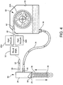
- the exemplary positive displacement pump 20 comprises a fluid cylinder 24, a reciprocating piston 25 ( Figure 4 ) inside the cylinder 24, and an elongated piston stem 26 surrounded by a heavy metal spring 28.
- the fluid cylinder 24 communicates with a fluid supply reservoir 30 and discharge manifold 32 through an assembly of inlet hoses 34, outlet hoses 35, and check valves 36.
- the piston 25 is designed to travel up and down inside the cylinder 24 along a compression stroke and an opposite extension stroke in response to a gravitational "bounce" of the vehicle 10 when in motion.
- each accumulator 40A, 40B has an internal flexible fluid bladder 41, and a preset degree of internal air pressure which functions to push against the bladder 41.
- the flow-control valves 39A, 39B operate to control the switching necessary to feed one accumulator 40A, 40B versus the other.
- the intake valve 39A will close off any additional flow and the output valve 39B will open, thereby allowing the pressurized fluid to be pushed out from a distal end of the outlet hose 35 and sprayed onto blades 22A of turbine 22.
- a nozzle 42 may be attached to the outlet hose 35 to accelerate the discharge of fluid.
- the flow valves 39A, 39B switch again-back and forth. This allows one accumulator 40A, 40B to be constantly spraying, while the other is filling, thereby creating a constant stream of pressurized fluid capable of rotating the turbine 22 without interruption. Spent fluid used to drive the turbine 22 passes back into the fluid reservoir 30 (arranged beneath the turbine 22) and is recycled in a circuit through the process described above.
- the exemplary reservoir 30 may comprise a baffle assembly 44 to limit sloshing when the vehicle is in motion.
- ultracapacitors 54 may be added between the generator 51 and batteries 52. Adding ultracapacitors 54 may overcome the need for a constant high spinning rate of the generator 51. Ultracapacitors 54 are able to collect and accumulate varying and low level power outputs, and then turn around and discharge at any desired output. Meaning, the ultracapacitor can collect a "trickle charge" varying around 1V-10V.
- the capacitor 54 Once the capacitor 54 has absorbed as much electrical energy as possible, it can then discharge its entire capacity via current controller 55 at any voltage rate desired in a quick burst. This enables the generator 51 to provide low voltage output, while still allowing the batteries 52 to be charged at the higher voltage necessary. The charged batteries 52 may then be used to power the vehicle's electric drive motor 56, electrical subsystems, and/or other onboard electrical devices.
- the present energy harvesting system may be incorporated in any other land vehicle, such as freight and passenger trains, motorcycles, dirt bikes, motorized scooters, two- wheeled motorized personal vehicles, golf carts, and any other such vehicles comprising passive, active, semi-active, dependant, independent, or semi-independent suspension systems.
- the exemplary energy harvesting systems may be incorporated in any type and style of water craft.
Description
- The present disclosure relates broadly and generally to a vehicle comprising a gravity-assist energy harvesting suspension system, and method for converting mechanical energy into electrical energy.
- In one exemplary embodiment, the present disclosure allows the constant gravitational effect on a vehicle in motion to be converted via mechanical means in to electrical energy. The power output depends on the weight of the vehicle (mass) and the speed at which the vehicle is moving-following the mathematical principle Energy ∗ Mass∗Speed^2. The closed-loop nature of the exemplary system, including all available pumps (for each wheel), allows for the entire mass of the vehicle to be used for power generation; as opposed to having four separate closed systems (one for each wheel), which would only benefit from the weight in a single designated corner of the vehicle. There are no emissions, no pollutants, and no external fuel source needed to produce the electrical power.
-
CH 458085 - According to one aspect the present invention comprises a vehicle as defined in
claim 1. The vehicle has a gravitational positive displacement that comprises a cylinder and a reciprocating piston inside the cylinder. The piston is adapted for (linear) movement along a compression stroke and an extension stroke in response to a gravitational bounce of the vehicle when in motion. A fluid inlet hose is connected to an onboard fluid source and to the displacement pump. The inlet hose is adapted for drawing fluid into the cylinder as the piston travels along its extension stroke. A fluid outlet hose is connected to the displacement pump, and has a distal end adapted for discharging fluid from the cylinder as the piston travels along its compression stroke. A turbine comprising a rotor shaft and attached blades is mounted relative to the distal end of the fluid outlet hose. Fluid discharged through the outlet hose acts on the blades, thereby moving and imparting rotational energy to the rotor shaft. A generator is operatively connected to the turbine, and is adapted for converting the rotational energy generated by the rotor shaft to electrical energy. A battery is operatively connected to the generator, and is adapted for storing the electrical energy produced by the generator to power electrical components (e.g., electrical subsystems, electric motors) of the vehicle. Such a vehicle is known fromCH 458 085 - The term "vehicle" refers broadly herein to any personal, passenger, recreational, commercial, or industrial land or water vehicle. The term "suspension system" refers to any one or more of the vehicle tires, tire air, springs, shock absorbers and linkages that connects the vehicle to its wheels and allows relative motion between the two. The term "fluid inlet hose" refers to any single continuous hose, or a plurality of individual but directly connected hoses, or a combination of directly connected hoses and indirectly connected hoses (meaning "in fluid-communication") which function to enable transfer of fluid from a fluid source to the positive displacement pump. Likewise, term "fluid outlet hose" refers to any single continuous hose, or a plurality of individual but directly connected hoses, or a combination of directly connected hoses and indirectly connected hoses (meaning "in fluid-communication") which function to enable transfer of fluid from the positive displacement pump to the turbine.
In an embodiment, the vehicle has a plurality of wheels, a frame carried on the wheels, and a suspension system operatively connecting the frame to the wheels. - According to another exemplary embodiment, an electric motor is operatively connected to the battery, and is adapted for propelling the vehicle.
- According to another exemplary embodiment, the positive displacement pump is substantially vertically-disposed between the wheels and the frame.
- According to another exemplary embodiment, the fluid outlet hose comprises a nozzle for accelerating fluid discharged through its distal end.
- According to another exemplary embodiment, respective flow control valves communicate with the fluid inlet and fluid outlet hoses.
- According to another exemplary embodiment, the vehicle comprises a plurality of gravitational positive displacement pumps, wherein a single pump is located adjacent each wheel of the vchiclc.
- According to another exemplary embodiment, the suspension system comprises a coil spring formed adjacent the gravitational positive displacement pump at each wheel of the vehicle.
- According to another exemplary embodiment, an electrochemical capacitor is located between the generator and the battery.
- According to another exemplary embodiment, the electrochemical capacitor comprises an ultracapacitor (or "supercapacitor").
- According to another exemplary embodiment, the onboard fluid source comprises a fluid collection reservoir located beneath the generator.
- According to another exemplary embodiment, the fluid collection reservoir comprises a baffle assembly adapted for limiting fluid slosh when the vehicle is in motion.
- Another aspect of the present invention comprises a method for converting mechanical energy into electrical energy for a vehicle as defined in claim 13.
- Exemplary embodiments of the present disclosure will hereinafter be described in conjunction with the following drawing figures, wherein like numerals denote like elements, and wherein:
-
Figure 1 is a side schematic view of an exemplary vehicle incorporating the present energy harvesting suspension system of the present disclosure; -
Figure 2 is a top plan schematic view of the exemplary vehicle incorporating the present energy harvesting suspension system; -
Figure 3 is a further schematic view illustrating operation of the hydraulic accumulators; -
Figure 4 is a further schematic view illustrating components of the fluid circuit in the present energy harvesting suspension system; and -
Figure 5 is a further schematic view illustrating operation of the hydroturbine and generator designed for charging a bank of vehicle batteries to power the vehicle's electric motor. - The present invention is described more fully hereinafter with reference to the accompanying drawings, in which one or more exemplary embodiments of the invention are shown. Like numbers used herein refer to like elements throughout. This invention may, however, be embodied in many different forms and should not be construed as limited to the embodiments set forth herein; rather, these embodiments are provided so that this disclosure will be operative, enabling, and complete. Accordingly, the particular arrangements disclosed are meant to be illustrative only and not limiting as to the scope of the invention, which is to be given the full breadth of the appended claims.
- Referring now specifically to the drawings, a vehicle comprising an energy harvesting suspension system according to one exemplary embodiment is illustrated in
Figure 1 , and shown generally atbroad reference numeral 10. Thepresent vehicle 10 incorporates conventional features, such aswheels 11 andtires 12, a frame assembly 14 (e.g., chassis) carried on thewheels 11, adriver seat 15, andsteering wheel 16. The exemplary suspension system operatively connects theframe assembly 14 to thewheels 11, and comprises four gravitationalpositive displacement pumps Figure 2 ). As described further below, thepositive displacement pumps 20A-20D cooperate to move fluid (e.g, water) used to drive ahydroturbine 22. Theexemplary turbine 22 may comprise Pelton or Turgo style wheel, both generally known and understood in the art. The components and operation of a singlepositive displacement pump 20A-referred to generically as pump 20-is described below, it being understood that the remaining threepumps 20B-20D comprise identical components and operate in an identical manner. - Referring to
Figures 1 ,2 and4 , the exemplarypositive displacement pump 20 comprises afluid cylinder 24, a reciprocating piston 25 (Figure 4 ) inside thecylinder 24, and anelongated piston stem 26 surrounded by aheavy metal spring 28. Thefluid cylinder 24 communicates with afluid supply reservoir 30 anddischarge manifold 32 through an assembly ofinlet hoses 34,outlet hoses 35, andcheck valves 36. Thepiston 25 is designed to travel up and down inside thecylinder 24 along a compression stroke and an opposite extension stroke in response to a gravitational "bounce" of thevehicle 10 when in motion. During the extension stroke, fluid is suctioned from thefluid supply reservoir 30 through theinlet hose 34 andcheck valves 36, and into a sealed fluid cavity 38 (Figure 4 ) of thecylinder 24. As thevehicle 10 bounces onspring 28 and theadjacent tire 12, the piston's compression stroke collapses thefluid cavity 38 insidecylinder 24 causing the fluid to discharge through theoutlet hose 35 and checkvalves 36, and into thedischarge manifold 32. The simple harmonic motion or oscillation of the movingvehicle 10 up and down on thespring 28 causes repeated gravity-induced actuation of thepiston 25 inside thefluid cylinder 24. In the exemplary embodiment, all four of thepositive displacement pumps 20A-20D operate simultaneously adjacentrespective wheels 11 of thevehicle 10 to transfer fluid from thefluid reservoir 30 to thedischarge manifold 32. If desired, the vehicle bounce may be dampened by adding various hydraulic gates, valves, and other fluids (e.g., gases) to eachdisplacement pump 20A-20D, such that the pumps function much like that of conventional shock absorbers. - Referring to
Figures 3 ,4 , and5 , from thedischarge manifold 32 fluid is moved throughoutlet hoses 35, electronic flow-control valves hydraulic accumulators accumulator flexible fluid bladder 41, and a preset degree of internal air pressure which functions to push against thebladder 41. The flow-control valves accumulator first accumulator 40A, theintake valve 39A will close off any additional flow and theoutput valve 39B will open, thereby allowing the pressurized fluid to be pushed out from a distal end of theoutlet hose 35 and sprayed ontoblades 22A ofturbine 22. Anozzle 42 may be attached to theoutlet hose 35 to accelerate the discharge of fluid. As thefirst accumulator 40A is emptying and spraying theturbine 22, theflow valves second accumulator 40B are opposite, meaning the flow that was feeding thefirst accumulator 40A will now be feeding thesecond accumulator 40B as the first is spraying. When thesecond accumulator 40B is full and thefirst accumulator 40A is empty, theflow valves accumulator turbine 22 without interruption. Spent fluid used to drive theturbine 22 passes back into the fluid reservoir 30 (arranged beneath the turbine 22) and is recycled in a circuit through the process described above. Theexemplary reservoir 30 may comprise abaffle assembly 44 to limit sloshing when the vehicle is in motion. - As best illustrated in
Figure 5 , as pressurized fluid is sprayed across theblades 22A of theturbine 22, actuation ofrotor shaft 22B acts upon an electric generator 51 (e.g., alternator) to create an electric current sufficient to charge a bank ofonboard vehicle batteries 52. Because the electrical power output of thegenerator 51 will vary depending on the available fluid flow, one ormore ultracapacitors 54 andcurrent controller 55 may be added between thegenerator 51 andbatteries 52. Addingultracapacitors 54 may overcome the need for a constant high spinning rate of thegenerator 51. Ultracapacitors 54 are able to collect and accumulate varying and low level power outputs, and then turn around and discharge at any desired output. Meaning, the ultracapacitor can collect a "trickle charge" varying around 1V-10V. Once thecapacitor 54 has absorbed as much electrical energy as possible, it can then discharge its entire capacity viacurrent controller 55 at any voltage rate desired in a quick burst. This enables thegenerator 51 to provide low voltage output, while still allowing thebatteries 52 to be charged at the higher voltage necessary. The chargedbatteries 52 may then be used to power the vehicle'selectric drive motor 56, electrical subsystems, and/or other onboard electrical devices. - In alternative exemplary embodiments, the present energy harvesting system may be incorporated in any other land vehicle, such as freight and passenger trains, motorcycles, dirt bikes, motorized scooters, two- wheeled motorized personal vehicles, golf carts, and any other such vehicles comprising passive, active, semi-active, dependant, independent, or semi-independent suspension systems. Additionally, the exemplary energy harvesting systems may be incorporated in any type and style of water craft.
Claims (13)
- A vehicle, comprising:a gravitational positive displacement pump (20) comprising a cylinder (24) and a reciprocating piston (25) inside said cylinder, said piston adapted for movement along a compression stroke and an opposite extension stroke in response to a gravitational bounce of said vehicle when in motion;an onboard fluid source (30);a fluid inlet hose (34) connected to said fluid source and said displacement pump, and adapted for drawing fluid into said cylinder as said piston travels along its extension stroke;a fluid outlet hose (35) having a proximal end connected to said displacement pump, and a distal end adapted for discharging fluid from said cylinder as said piston travels along its compression stroke;first and second hydraulic accumulators (40A, 40B) located between the proximal and distal ends of said fluid outlet hose;a fluid control manifold (32) communicating with said fluid outlet hose, and adapted for selectively directing fluid to one of said first and second hydraulic accumulators;a turbine (22) comprising a rotor shaft (22B) and attached blades (22A), said turbine mounted relative to the distal end of said fluid outlet hose such that fluid discharged through said outlet hose acts on said blades thereby moving and imparting rotational energy to the rotor shaft;a generator (51) operatively connected to said turbine, and adapted for converting the rotational energy generated by said rotor shaft to electrical energy; anda battery (52) operatively connected to said generator, and adapted for storing the electrical energy produced by said generator to power electrical components of said vehicle.
- A vehicle (10) according to claim 1, comprising:a plurality of wheels (11);a frame (14) carried on said wheels;a suspension system (20A-D) operatively connecting said frame to said wheels;the gravitational positive displacement pump (20) operatively mounted between said wheels and said frame.
- The vehicle according to any one of the preceding claims, and comprising an electric motor (56) operatively connected to said battery, and adapted for propelling said vehicle.
- The vehicle according to any one of the preceding claims, wherein said positive displacement pump is substantially vertically-disposed between said wheels and said frame.
- The vehicle according to any one of the preceding claims, wherein said fluid outlet hose comprises a nozzle (42) for accelerating fluid discharged through its distal end.
- The vehicle according to any one of the preceding claims, and comprising respective flow control valves (36, 39A, 39B) communicating with said fluid inlet and fluid outlet hoses.
- The vehicle according to any claim 2, and comprising a plurality of gravitational positive displacement pumps, wherein a single pump is located adjacent each wheel of said vehicle.
- The vehicle according to claim 7, wherein said suspension system comprises a coil spring (28) formed adjacent said gravitational positive displacement pump at each wheel of said vehicle.
- The vehicle according to any one of the preceding claims, and comprising an electrochemical capacitor (54) located between said generator and said battery.
- The vehicle according to claim 9, wherein said electrochemical capacitor comprises an ultracapacitor.
- The vehicle according to any one of the preceding claims, wherein said onboard fluid source comprises a fluid collection reservoir located beneath said generator.
- The vehicle according to claim 11, wherein said fluid collection reservoir comprises a baffle assembly (44) adapted for limiting fluid slosh when said vehicle is in motion.
- A method for converting mechanical energy into electrical energy for a vehicle (10), comprising: installing a gravitational positive displacement pump (20) in the vehicle, the displacement pump comprising a cylinder (24) and a reciprocating piston (25) inside the cylinder, the piston adapted for movement along a compression stroke and an extension stroke in response to a gravitational bounce of the vehicle when in motion;
drawing fluid into the cylinder of the displacement pump through a fluid inlet hose (34) as the piston travels along its extension stroke;
discharging fluid from the cylinder through a fluid outlet hose (35) as the piston travels along its compression stroke;
locating first and second hydraulic accumulators (40A, 40B) between proximal and distal ends of the fluid outlet hose; mounting a fluid control manifold (32) communicating with said fluid outlet hose;
selectively directing fluid from the fluid control manifold to one of the first and second hydraulic accumulators;
mounting a turbine (22) relative to a distal end of the fluid outlet hose, such that fluid discharged through the outlet hose imparts rotational energy to the turbine;
operatively connecting a generator (51) to the turbine to convert the rotational energy generated by the turbine to electrical energy; and
storing the electrical energy produced by the generator in a battery (52) to power electrical components of the vehicle.
Priority Applications (1)
| Application Number | Priority Date | Filing Date | Title |
|---|---|---|---|
| PL16862599T PL3370985T3 (en) | 2015-11-06 | 2016-11-07 | Vehicle comprising energy harvesting suspension system, and method for converting mechanical energy into electrical energy |
Applications Claiming Priority (2)
| Application Number | Priority Date | Filing Date | Title |
|---|---|---|---|
| US201562252046P | 2015-11-06 | 2015-11-06 | |
| PCT/US2016/000106 WO2017078760A1 (en) | 2015-11-06 | 2016-11-07 | Vehicle comparising energy harvesting suspension system, and method for converting mechanical energy into electrical energy |
Publications (3)
| Publication Number | Publication Date |
|---|---|
| EP3370985A1 EP3370985A1 (en) | 2018-09-12 |
| EP3370985A4 EP3370985A4 (en) | 2019-07-10 |
| EP3370985B1 true EP3370985B1 (en) | 2021-04-28 |
Family
ID=58662623
Family Applications (1)
| Application Number | Title | Priority Date | Filing Date |
|---|---|---|---|
| EP16862599.4A Active EP3370985B1 (en) | 2015-11-06 | 2016-11-07 | Vehicle comprising energy harvesting suspension system, and method for converting mechanical energy into electrical energy |
Country Status (9)
| Country | Link |
|---|---|
| US (4) | US10583707B2 (en) |
| EP (1) | EP3370985B1 (en) |
| JP (1) | JP6625234B2 (en) |
| AU (1) | AU2016350551B2 (en) |
| CA (1) | CA3004407C (en) |
| DK (1) | DK3370985T3 (en) |
| ES (1) | ES2881466T3 (en) |
| PL (1) | PL3370985T3 (en) |
| WO (1) | WO2017078760A1 (en) |
Families Citing this family (12)
| Publication number | Priority date | Publication date | Assignee | Title |
|---|---|---|---|---|
| US11046165B2 (en) * | 2015-08-27 | 2021-06-29 | Joseph Hogan | Vehicle hydraulic power system |
| AU2016350551B2 (en) * | 2015-11-06 | 2019-01-17 | Matthew Alan Kaskowicz | Vehicle comprising energy harvesting suspension system, and method for converting mechanical energy into electrical energy |
| CN108928419B (en) * | 2017-05-23 | 2020-06-16 | 睿能创意公司 | Vehicle with a steering wheel |
| US10793012B2 (en) * | 2018-01-26 | 2020-10-06 | Gray Alexander Cash | Magnetic energy convertor for vehicle axles |
| US11746751B1 (en) * | 2018-02-03 | 2023-09-05 | Carlos Gabriel Oroza | Airflow power generating apparatus |
| ES2670435A1 (en) * | 2018-03-06 | 2018-05-30 | Antonio GARCIA LOPEZ | AUTO-COMPENSATED DAMPING SYSTEM FOR VEHICLES (Machine-translation by Google Translate, not legally binding) |
| CN110500249A (en) * | 2019-09-23 | 2019-11-26 | 尹全一 | A kind of mobile generator having damping and accumulation of energy function concurrently |
| US20220074416A1 (en) * | 2020-09-09 | 2022-03-10 | Robert M Pangonis | Fluid Flow Power Delivery System |
| US20220258554A1 (en) * | 2021-02-17 | 2022-08-18 | Francis Walls | Kinetic Energy Shock Absorber |
| KR20220120223A (en) * | 2021-02-23 | 2022-08-30 | 현대자동차주식회사 | Eop control method for powertrain of vehicle |
| US20230024676A1 (en) | 2021-07-22 | 2023-01-26 | Gonzalo Fuentes Iriarte | Systems and methods for electric vehicle energy recovery |
| US11643168B1 (en) | 2022-04-05 | 2023-05-09 | Victor Rafael Cataluna | Through-hull passive inboard hydro-generator for a marine vessel |
Family Cites Families (38)
| Publication number | Priority date | Publication date | Assignee | Title |
|---|---|---|---|---|
| US3507580A (en) * | 1967-05-12 | 1970-04-21 | Landon H Howard | Energy generator |
| CH458085A (en) * | 1967-11-28 | 1968-06-15 | Poterat Jacques | Vehicle |
| FR2254453A1 (en) * | 1973-12-18 | 1975-07-11 | Danielli Nicolas | Braking energy recovery system for automobile - has pump operated by brake friction passing liquid to pressure accumulator |
| US4295538A (en) * | 1974-03-21 | 1981-10-20 | Lewus Alexander J | Auxiliary power system for automotive vehicle |
| US4032829A (en) * | 1975-08-22 | 1977-06-28 | Schenavar Harold E | Road shock energy converter for charging vehicle batteries |
| US4024926A (en) * | 1975-09-15 | 1977-05-24 | Aristotel Butoi | Energy system for self-propelled vehicles |
| US5091679A (en) * | 1990-06-20 | 1992-02-25 | General Motors Corporation | Active vehicle suspension with brushless dynamoelectric actuator |
| JPH078159U (en) * | 1993-07-09 | 1995-02-03 | 坂本工業株式会社 | Vehicle tank |
| US5570286A (en) * | 1993-12-23 | 1996-10-29 | Lord Corporation | Regenerative system including an energy transformer which requires no external power source to drive same |
| JPH08226377A (en) * | 1994-12-09 | 1996-09-03 | Fuotsukusu Hetsudo:Kk | Surge generator |
| US5590734A (en) * | 1994-12-22 | 1997-01-07 | Caires; Richard | Vehicle and method of driving the same |
| IT1289322B1 (en) * | 1996-01-19 | 1998-10-02 | Carlo Alberto Zenobi | DEVICE FOR OBTAINING ELECTRICITY FROM THE DYNAMIC ACTIONS ARISING FROM THE RELATIVE MOTION BETWEEN VEHICLES AND THE GROUND |
| US6758295B2 (en) * | 2002-04-08 | 2004-07-06 | Patrick Fleming | Turbine generator regenerative braking system |
| US7387182B2 (en) * | 2002-04-08 | 2008-06-17 | Patrick Fleming | Turbine generator regenerative braking system |
| ITBO20040278A1 (en) * | 2004-05-03 | 2004-08-03 | Ferrari Spa | AUTOMOTIVE SUSPENSION WITH RESPONSE CONTROL OF THE SPRING-SHOCK ASSEMBLY. |
| US7357427B2 (en) * | 2004-06-25 | 2008-04-15 | Kelsan Technologies Corp. | Method and apparatus for applying liquid compositions in rail systems |
| US7261171B2 (en) * | 2005-10-24 | 2007-08-28 | Towertech Research Group | Apparatus and method for converting movements of a vehicle wheel to electricity for charging a battery of the vehicle |
| EP1878598A1 (en) * | 2006-07-13 | 2008-01-16 | Fondazione Torino Wireless | Regenerative suspension for a vehicle |
| US7938217B2 (en) * | 2008-03-11 | 2011-05-10 | Physics Lab Of Lake Havasu, Llc | Regenerative suspension with accumulator systems and methods |
| US8807258B2 (en) * | 2008-03-11 | 2014-08-19 | Physics Lab Of Lake Havasu, Llc | Regenerative suspension with accumulator systems and methods |
| US8261865B2 (en) * | 2008-03-11 | 2012-09-11 | Physics Lab Of Lake Havasu, Llc | Regenerative suspension with accumulator systems and methods |
| US8839920B2 (en) * | 2008-04-17 | 2014-09-23 | Levant Power Corporation | Hydraulic energy transfer |
| US8376100B2 (en) * | 2008-04-17 | 2013-02-19 | Levant Power Corporation | Regenerative shock absorber |
| US8098040B1 (en) * | 2008-06-25 | 2012-01-17 | David Chandler Botto | Ram air driven turbine generator battery charging system using control of turbine generator torque to extend the range of an electric vehicle |
| US8063498B2 (en) * | 2009-02-27 | 2011-11-22 | GM Global Technology Operations LLC | Harvesting energy from vehicular vibrations |
| US8344526B2 (en) * | 2009-03-25 | 2013-01-01 | Bhat Nikhil | Energy generating supports |
| US8513824B2 (en) * | 2010-03-16 | 2013-08-20 | Chun Shig SOHN | Suspension system for vehicle |
| JP4697348B1 (en) * | 2010-09-01 | 2011-06-08 | 明彦 岡本 | Energy regeneration device for hybrid or electric vehicle |
| CN106183772B (en) | 2011-03-21 | 2018-08-21 | 达纳比利时股份有限公司 | The hydrostatic power transmission system and its optimization method of accumulator auxiliary |
| US8966889B2 (en) * | 2011-11-01 | 2015-03-03 | Tenneco Automotive Operating Company Inc. | Energy harvesting passive and active suspension |
| US8820064B2 (en) * | 2012-10-25 | 2014-09-02 | Tenneco Automotive Operating Company Inc. | Recuperating passive and active suspension |
| KR101416362B1 (en) * | 2012-11-15 | 2014-08-07 | 현대자동차 주식회사 | Energy regeneration device of suspension system for vehicle |
| US9481221B2 (en) * | 2013-01-08 | 2016-11-01 | Tenneco Automotive Operating Company Inc. | Passive and active suspension with optimization of energy usage |
| JP6613233B2 (en) * | 2013-06-26 | 2019-11-27 | パーカー ハニフィン マニュファクチャリング リミテッド | Energy efficient electric vehicle control system |
| EP3233543A1 (en) * | 2014-12-19 | 2017-10-25 | Sistemi Sospensioni S.p.A. | Regenerative hydraulic shock-absorber for vehicle suspension |
| US9738162B2 (en) * | 2015-03-16 | 2017-08-22 | Viatec, Inc. | Electro-hydraulic hybrid system |
| AU2016350551B2 (en) | 2015-11-06 | 2019-01-17 | Matthew Alan Kaskowicz | Vehicle comprising energy harvesting suspension system, and method for converting mechanical energy into electrical energy |
| US20190299735A1 (en) * | 2018-03-30 | 2019-10-03 | AISIN Technical Center of America, Inc. | Active regenerative damper system |
-
2016
- 2016-11-07 AU AU2016350551A patent/AU2016350551B2/en active Active
- 2016-11-07 WO PCT/US2016/000106 patent/WO2017078760A1/en active Application Filing
- 2016-11-07 EP EP16862599.4A patent/EP3370985B1/en active Active
- 2016-11-07 ES ES16862599T patent/ES2881466T3/en active Active
- 2016-11-07 PL PL16862599T patent/PL3370985T3/en unknown
- 2016-11-07 CA CA3004407A patent/CA3004407C/en active Active
- 2016-11-07 JP JP2018544019A patent/JP6625234B2/en active Active
- 2016-11-07 DK DK16862599.4T patent/DK3370985T3/en active
- 2016-11-07 US US15/771,608 patent/US10583707B2/en active Active
-
2020
- 2020-03-03 US US16/807,651 patent/US10723193B2/en active Active
- 2020-06-25 US US16/911,983 patent/US11203242B2/en active Active
-
2021
- 2021-12-15 US US17/552,085 patent/US11648809B1/en active Active
Non-Patent Citations (1)
| Title |
|---|
| None * |
Also Published As
| Publication number | Publication date |
|---|---|
| US20180304713A1 (en) | 2018-10-25 |
| AU2016350551A1 (en) | 2018-05-24 |
| AU2016350551B2 (en) | 2019-01-17 |
| EP3370985A4 (en) | 2019-07-10 |
| US10723193B2 (en) | 2020-07-28 |
| JP6625234B2 (en) | 2019-12-25 |
| US11203242B2 (en) | 2021-12-21 |
| CA3004407C (en) | 2020-05-19 |
| US11648809B1 (en) | 2023-05-16 |
| PL3370985T3 (en) | 2021-11-29 |
| DK3370985T3 (en) | 2021-08-09 |
| ES2881466T3 (en) | 2021-11-29 |
| US20200198428A1 (en) | 2020-06-25 |
| JP2018532654A (en) | 2018-11-08 |
| US10583707B2 (en) | 2020-03-10 |
| WO2017078760A1 (en) | 2017-05-11 |
| CA3004407A1 (en) | 2017-05-11 |
| EP3370985A1 (en) | 2018-09-12 |
| US20200324601A1 (en) | 2020-10-15 |
Similar Documents
| Publication | Publication Date | Title |
|---|---|---|
| EP3370985B1 (en) | Vehicle comprising energy harvesting suspension system, and method for converting mechanical energy into electrical energy | |
| EP2276640B1 (en) | Regenerative shock absorber | |
| CN102481821B (en) | For the generating suspension system of hybrid electric vehicle and battery-driven car | |
| JP4697348B1 (en) | Energy regeneration device for hybrid or electric vehicle | |
| US20070089924A1 (en) | Apparatus and method for hydraulically converting movement of a vehicle wheel to electricity for charging a vehicle battery | |
| US20160243776A1 (en) | Compression Tires and Tire Systems | |
| US8624409B2 (en) | Shock absorber electrical generator | |
| CN202165506U (en) | Power generation shock absorber | |
| CN106183686A (en) | A kind of oil gas actively interconnects energy regenerative suspension | |
| JP2011025901A (en) | Suspension hydraulic power generation system | |
| CN204846107U (en) | Two -wheeled is totally closed from generating electricity electric motor car | |
| JP4571211B2 (en) | Vehicle power generation device | |
| CN109109603B (en) | Interactive automobile hydraulic independent suspension system | |
| CN109760528A (en) | The electric car of automatic hydraulic charging in a kind of traveling | |
| KR102344506B1 (en) | An automobile | |
| WO2019175572A1 (en) | Electric vehicle with an electro-hydraulic propulsion system | |
| CN210526320U (en) | Electric automobile capable of being automatically hydraulically charged during running | |
| WO2022023824A1 (en) | Tire pump clean energy generator | |
| CN110605981A (en) | Energy storage electric vehicle | |
| CN202518113U (en) | Self-charging equipment of electric vehicle | |
| GB2254301A (en) | Electrically powered vehicles | |
| KR101301654B1 (en) | Suspension System using hydraulic generation for vehicle | |
| PH12014000224A1 (en) | ``gravity`` the free energy for vehicle | |
| ITPT990010A1 (en) | DEVICE FOR THE RECOVERY OF ENERGY FROM MOTOR VEHICLE SUSPENSIONS IN GENERAL. |
Legal Events
| Date | Code | Title | Description |
|---|---|---|---|
| STAA | Information on the status of an ep patent application or granted ep patent |
Free format text: STATUS: THE INTERNATIONAL PUBLICATION HAS BEEN MADE |
|
| PUAI | Public reference made under article 153(3) epc to a published international application that has entered the european phase |
Free format text: ORIGINAL CODE: 0009012 |
|
| STAA | Information on the status of an ep patent application or granted ep patent |
Free format text: STATUS: REQUEST FOR EXAMINATION WAS MADE |
|
| 17P | Request for examination filed |
Effective date: 20180502 |
|
| AK | Designated contracting states |
Kind code of ref document: A1 Designated state(s): AL AT BE BG CH CY CZ DE DK EE ES FI FR GB GR HR HU IE IS IT LI LT LU LV MC MK MT NL NO PL PT RO RS SE SI SK SM TR |
|
| AX | Request for extension of the european patent |
Extension state: BA ME |
|
| RAP1 | Party data changed (applicant data changed or rights of an application transferred) |
Owner name: KASKOWICZ, MATTHEW, ALAN |
|
| RIN1 | Information on inventor provided before grant (corrected) |
Inventor name: KASKOWICZ, MATTHEW, ALAN |
|
| DAV | Request for validation of the european patent (deleted) | ||
| DAX | Request for extension of the european patent (deleted) | ||
| A4 | Supplementary search report drawn up and despatched |
Effective date: 20190613 |
|
| RIC1 | Information provided on ipc code assigned before grant |
Ipc: F03G 7/00 20060101ALI20190606BHEP Ipc: F03G 7/08 20060101ALI20190606BHEP Ipc: B60K 25/10 20060101ALI20190606BHEP Ipc: B60G 13/14 20060101ALI20190606BHEP Ipc: F03B 13/00 20060101ALI20190606BHEP Ipc: B60K 1/04 20190101ALI20190606BHEP Ipc: B60G 13/00 20060101AFI20190606BHEP Ipc: F15B 1/027 20060101ALI20190606BHEP Ipc: F03B 1/00 20060101ALI20190606BHEP Ipc: F16F 15/023 20060101ALI20190606BHEP |
|
| RIC1 | Information provided on ipc code assigned before grant |
Ipc: F03G 7/08 20060101ALI20201111BHEP Ipc: F03B 1/00 20060101ALI20201111BHEP Ipc: F16F 15/023 20060101ALI20201111BHEP Ipc: F15B 1/027 20060101ALI20201111BHEP Ipc: B60G 13/14 20060101ALI20201111BHEP Ipc: B60K 25/10 20060101ALI20201111BHEP Ipc: F03B 13/00 20060101ALI20201111BHEP Ipc: B60K 1/04 20190101ALI20201111BHEP Ipc: F03G 7/00 20060101ALI20201111BHEP Ipc: B60G 13/00 20060101AFI20201111BHEP |
|
| GRAP | Despatch of communication of intention to grant a patent |
Free format text: ORIGINAL CODE: EPIDOSNIGR1 |
|
| STAA | Information on the status of an ep patent application or granted ep patent |
Free format text: STATUS: GRANT OF PATENT IS INTENDED |
|
| INTG | Intention to grant announced |
Effective date: 20210121 |
|
| GRAS | Grant fee paid |
Free format text: ORIGINAL CODE: EPIDOSNIGR3 |
|
| GRAA | (expected) grant |
Free format text: ORIGINAL CODE: 0009210 |
|
| STAA | Information on the status of an ep patent application or granted ep patent |
Free format text: STATUS: THE PATENT HAS BEEN GRANTED |
|
| AK | Designated contracting states |
Kind code of ref document: B1 Designated state(s): AL AT BE BG CH CY CZ DE DK EE ES FI FR GB GR HR HU IE IS IT LI LT LU LV MC MK MT NL NO PL PT RO RS SE SI SK SM TR |
|
| REG | Reference to a national code |
Ref country code: GB Ref legal event code: FG4D |
|
| REG | Reference to a national code |
Ref country code: CH Ref legal event code: EP |
|
| REG | Reference to a national code |
Ref country code: AT Ref legal event code: REF Ref document number: 1386680 Country of ref document: AT Kind code of ref document: T Effective date: 20210515 |
|
| REG | Reference to a national code |
Ref country code: DE Ref legal event code: R096 Ref document number: 602016057101 Country of ref document: DE |
|
| REG | Reference to a national code |
Ref country code: IE Ref legal event code: FG4D |
|
| REG | Reference to a national code |
Ref country code: NL Ref legal event code: FP |
|
| REG | Reference to a national code |
Ref country code: DK Ref legal event code: T3 Effective date: 20210802 |
|
| REG | Reference to a national code |
Ref country code: SE Ref legal event code: TRGR |
|
| REG | Reference to a national code |
Ref country code: LT Ref legal event code: MG9D |
|
| REG | Reference to a national code |
Ref country code: NO Ref legal event code: T2 Effective date: 20210428 |
|
| PG25 | Lapsed in a contracting state [announced via postgrant information from national office to epo] |
Ref country code: HR Free format text: LAPSE BECAUSE OF FAILURE TO SUBMIT A TRANSLATION OF THE DESCRIPTION OR TO PAY THE FEE WITHIN THE PRESCRIBED TIME-LIMIT Effective date: 20210428 Ref country code: BG Free format text: LAPSE BECAUSE OF FAILURE TO SUBMIT A TRANSLATION OF THE DESCRIPTION OR TO PAY THE FEE WITHIN THE PRESCRIBED TIME-LIMIT Effective date: 20210728 Ref country code: LT Free format text: LAPSE BECAUSE OF FAILURE TO SUBMIT A TRANSLATION OF THE DESCRIPTION OR TO PAY THE FEE WITHIN THE PRESCRIBED TIME-LIMIT Effective date: 20210428 Ref country code: FI Free format text: LAPSE BECAUSE OF FAILURE TO SUBMIT A TRANSLATION OF THE DESCRIPTION OR TO PAY THE FEE WITHIN THE PRESCRIBED TIME-LIMIT Effective date: 20210428 |
|
| REG | Reference to a national code |
Ref country code: ES Ref legal event code: FG2A Ref document number: 2881466 Country of ref document: ES Kind code of ref document: T3 Effective date: 20211129 |
|
| PG25 | Lapsed in a contracting state [announced via postgrant information from national office to epo] |
Ref country code: LV Free format text: LAPSE BECAUSE OF FAILURE TO SUBMIT A TRANSLATION OF THE DESCRIPTION OR TO PAY THE FEE WITHIN THE PRESCRIBED TIME-LIMIT Effective date: 20210428 Ref country code: GR Free format text: LAPSE BECAUSE OF FAILURE TO SUBMIT A TRANSLATION OF THE DESCRIPTION OR TO PAY THE FEE WITHIN THE PRESCRIBED TIME-LIMIT Effective date: 20210729 Ref country code: IS Free format text: LAPSE BECAUSE OF FAILURE TO SUBMIT A TRANSLATION OF THE DESCRIPTION OR TO PAY THE FEE WITHIN THE PRESCRIBED TIME-LIMIT Effective date: 20210828 Ref country code: PT Free format text: LAPSE BECAUSE OF FAILURE TO SUBMIT A TRANSLATION OF THE DESCRIPTION OR TO PAY THE FEE WITHIN THE PRESCRIBED TIME-LIMIT Effective date: 20210830 Ref country code: RS Free format text: LAPSE BECAUSE OF FAILURE TO SUBMIT A TRANSLATION OF THE DESCRIPTION OR TO PAY THE FEE WITHIN THE PRESCRIBED TIME-LIMIT Effective date: 20210428 |
|
| PG25 | Lapsed in a contracting state [announced via postgrant information from national office to epo] |
Ref country code: EE Free format text: LAPSE BECAUSE OF FAILURE TO SUBMIT A TRANSLATION OF THE DESCRIPTION OR TO PAY THE FEE WITHIN THE PRESCRIBED TIME-LIMIT Effective date: 20210428 Ref country code: CZ Free format text: LAPSE BECAUSE OF FAILURE TO SUBMIT A TRANSLATION OF THE DESCRIPTION OR TO PAY THE FEE WITHIN THE PRESCRIBED TIME-LIMIT Effective date: 20210428 Ref country code: RO Free format text: LAPSE BECAUSE OF FAILURE TO SUBMIT A TRANSLATION OF THE DESCRIPTION OR TO PAY THE FEE WITHIN THE PRESCRIBED TIME-LIMIT Effective date: 20210428 Ref country code: SM Free format text: LAPSE BECAUSE OF FAILURE TO SUBMIT A TRANSLATION OF THE DESCRIPTION OR TO PAY THE FEE WITHIN THE PRESCRIBED TIME-LIMIT Effective date: 20210428 Ref country code: SK Free format text: LAPSE BECAUSE OF FAILURE TO SUBMIT A TRANSLATION OF THE DESCRIPTION OR TO PAY THE FEE WITHIN THE PRESCRIBED TIME-LIMIT Effective date: 20210428 |
|
| REG | Reference to a national code |
Ref country code: DE Ref legal event code: R097 Ref document number: 602016057101 Country of ref document: DE |
|
| PLBE | No opposition filed within time limit |
Free format text: ORIGINAL CODE: 0009261 |
|
| STAA | Information on the status of an ep patent application or granted ep patent |
Free format text: STATUS: NO OPPOSITION FILED WITHIN TIME LIMIT |
|
| 26N | No opposition filed |
Effective date: 20220131 |
|
| PG25 | Lapsed in a contracting state [announced via postgrant information from national office to epo] |
Ref country code: IS Free format text: LAPSE BECAUSE OF FAILURE TO SUBMIT A TRANSLATION OF THE DESCRIPTION OR TO PAY THE FEE WITHIN THE PRESCRIBED TIME-LIMIT Effective date: 20210828 Ref country code: AL Free format text: LAPSE BECAUSE OF FAILURE TO SUBMIT A TRANSLATION OF THE DESCRIPTION OR TO PAY THE FEE WITHIN THE PRESCRIBED TIME-LIMIT Effective date: 20210428 |
|
| PG25 | Lapsed in a contracting state [announced via postgrant information from national office to epo] |
Ref country code: MC Free format text: LAPSE BECAUSE OF FAILURE TO SUBMIT A TRANSLATION OF THE DESCRIPTION OR TO PAY THE FEE WITHIN THE PRESCRIBED TIME-LIMIT Effective date: 20210428 |
|
| PG25 | Lapsed in a contracting state [announced via postgrant information from national office to epo] |
Ref country code: LU Free format text: LAPSE BECAUSE OF NON-PAYMENT OF DUE FEES Effective date: 20211107 |
|
| PGFP | Annual fee paid to national office [announced via postgrant information from national office to epo] |
Ref country code: PL Payment date: 20221108 Year of fee payment: 7 Ref country code: BE Payment date: 20221110 Year of fee payment: 7 |
|
| PG25 | Lapsed in a contracting state [announced via postgrant information from national office to epo] |
Ref country code: HU Free format text: LAPSE BECAUSE OF FAILURE TO SUBMIT A TRANSLATION OF THE DESCRIPTION OR TO PAY THE FEE WITHIN THE PRESCRIBED TIME-LIMIT; INVALID AB INITIO Effective date: 20161107 |
|
| PG25 | Lapsed in a contracting state [announced via postgrant information from national office to epo] |
Ref country code: CY Free format text: LAPSE BECAUSE OF FAILURE TO SUBMIT A TRANSLATION OF THE DESCRIPTION OR TO PAY THE FEE WITHIN THE PRESCRIBED TIME-LIMIT Effective date: 20210428 |
|
| PGFP | Annual fee paid to national office [announced via postgrant information from national office to epo] |
Ref country code: NL Payment date: 20231025 Year of fee payment: 8 |
|
| PGFP | Annual fee paid to national office [announced via postgrant information from national office to epo] |
Ref country code: GB Payment date: 20231026 Year of fee payment: 8 |
|
| PGFP | Annual fee paid to national office [announced via postgrant information from national office to epo] |
Ref country code: ES Payment date: 20231204 Year of fee payment: 8 |
|
| PGFP | Annual fee paid to national office [announced via postgrant information from national office to epo] |
Ref country code: TR Payment date: 20231020 Year of fee payment: 8 Ref country code: SE Payment date: 20231026 Year of fee payment: 8 Ref country code: NO Payment date: 20231025 Year of fee payment: 8 Ref country code: IT Payment date: 20231019 Year of fee payment: 8 Ref country code: IE Payment date: 20231026 Year of fee payment: 8 Ref country code: FR Payment date: 20231026 Year of fee payment: 8 Ref country code: DK Payment date: 20231122 Year of fee payment: 8 Ref country code: DE Payment date: 20231024 Year of fee payment: 8 Ref country code: CH Payment date: 20231201 Year of fee payment: 8 Ref country code: AT Payment date: 20231024 Year of fee payment: 8 |
|
| PGFP | Annual fee paid to national office [announced via postgrant information from national office to epo] |
Ref country code: PL Payment date: 20231019 Year of fee payment: 8 Ref country code: BE Payment date: 20231025 Year of fee payment: 8 |