EP3370609B1 - Verfahren und vorrichtung zur beurteilung des zugangsflusses bei hämodialysepatienten durch videobildverarbeitung - Google Patents
Verfahren und vorrichtung zur beurteilung des zugangsflusses bei hämodialysepatienten durch videobildverarbeitung Download PDFInfo
- Publication number
- EP3370609B1 EP3370609B1 EP16862787.5A EP16862787A EP3370609B1 EP 3370609 B1 EP3370609 B1 EP 3370609B1 EP 16862787 A EP16862787 A EP 16862787A EP 3370609 B1 EP3370609 B1 EP 3370609B1
- Authority
- EP
- European Patent Office
- Prior art keywords
- motion
- video
- patient
- medical imaging
- imaging device
- Prior art date
- Legal status (The legal status is an assumption and is not a legal conclusion. Google has not performed a legal analysis and makes no representation as to the accuracy of the status listed.)
- Active
Links
Images


Classifications
-
- A—HUMAN NECESSITIES
- A61—MEDICAL OR VETERINARY SCIENCE; HYGIENE
- A61B—DIAGNOSIS; SURGERY; IDENTIFICATION
- A61B5/00—Measuring for diagnostic purposes; Identification of persons
- A61B5/02—Detecting, measuring or recording for evaluating the cardiovascular system, e.g. pulse, heart rate, blood pressure or blood flow
- A61B5/026—Measuring blood flow
- A61B5/0261—Measuring blood flow using optical means, e.g. infrared light
-
- A—HUMAN NECESSITIES
- A61—MEDICAL OR VETERINARY SCIENCE; HYGIENE
- A61B—DIAGNOSIS; SURGERY; IDENTIFICATION
- A61B5/00—Measuring for diagnostic purposes; Identification of persons
- A61B5/0059—Measuring for diagnostic purposes; Identification of persons using light, e.g. diagnosis by transillumination, diascopy, fluorescence
- A61B5/0077—Devices for viewing the surface of the body, e.g. camera, magnifying lens
-
- A—HUMAN NECESSITIES
- A61—MEDICAL OR VETERINARY SCIENCE; HYGIENE
- A61B—DIAGNOSIS; SURGERY; IDENTIFICATION
- A61B5/00—Measuring for diagnostic purposes; Identification of persons
- A61B5/68—Arrangements of detecting, measuring or recording means, e.g. sensors, in relation to patient
- A61B5/6801—Arrangements of detecting, measuring or recording means, e.g. sensors, in relation to patient specially adapted to be attached to or worn on the body surface
- A61B5/6813—Specially adapted to be attached to a specific body part
- A61B5/6824—Arm or wrist
-
- A—HUMAN NECESSITIES
- A61—MEDICAL OR VETERINARY SCIENCE; HYGIENE
- A61B—DIAGNOSIS; SURGERY; IDENTIFICATION
- A61B5/00—Measuring for diagnostic purposes; Identification of persons
- A61B5/70—Means for positioning the patient in relation to the detecting, measuring or recording means
- A61B5/702—Posture restraints
-
- A—HUMAN NECESSITIES
- A61—MEDICAL OR VETERINARY SCIENCE; HYGIENE
- A61M—DEVICES FOR INTRODUCING MEDIA INTO, OR ONTO, THE BODY; DEVICES FOR TRANSDUCING BODY MEDIA OR FOR TAKING MEDIA FROM THE BODY; DEVICES FOR PRODUCING OR ENDING SLEEP OR STUPOR
- A61M1/00—Suction or pumping devices for medical purposes; Devices for carrying-off, for treatment of, or for carrying-over, body-liquids; Drainage systems
- A61M1/14—Dialysis systems; Artificial kidneys; Blood oxygenators ; Reciprocating systems for treatment of body fluids, e.g. single needle systems for hemofiltration or pheresis
-
- A—HUMAN NECESSITIES
- A61—MEDICAL OR VETERINARY SCIENCE; HYGIENE
- A61M—DEVICES FOR INTRODUCING MEDIA INTO, OR ONTO, THE BODY; DEVICES FOR TRANSDUCING BODY MEDIA OR FOR TAKING MEDIA FROM THE BODY; DEVICES FOR PRODUCING OR ENDING SLEEP OR STUPOR
- A61M1/00—Suction or pumping devices for medical purposes; Devices for carrying-off, for treatment of, or for carrying-over, body-liquids; Drainage systems
- A61M1/36—Other treatment of blood in a by-pass of the natural circulatory system, e.g. temperature adaptation, irradiation ; Extra-corporeal blood circuits
- A61M1/3621—Extra-corporeal blood circuits
- A61M1/3653—Interfaces between patient blood circulation and extra-corporal blood circuit
- A61M1/3656—Monitoring patency or flow at connection sites; Detecting disconnections
-
- G—PHYSICS
- G06—COMPUTING OR CALCULATING; COUNTING
- G06T—IMAGE DATA PROCESSING OR GENERATION, IN GENERAL
- G06T7/00—Image analysis
- G06T7/0002—Inspection of images, e.g. flaw detection
- G06T7/0012—Biomedical image inspection
-
- G—PHYSICS
- G06—COMPUTING OR CALCULATING; COUNTING
- G06T—IMAGE DATA PROCESSING OR GENERATION, IN GENERAL
- G06T7/00—Image analysis
- G06T7/0002—Inspection of images, e.g. flaw detection
- G06T7/0012—Biomedical image inspection
- G06T7/0014—Biomedical image inspection using an image reference approach
- G06T7/0016—Biomedical image inspection using an image reference approach involving temporal comparison
-
- G—PHYSICS
- G06—COMPUTING OR CALCULATING; COUNTING
- G06T—IMAGE DATA PROCESSING OR GENERATION, IN GENERAL
- G06T7/00—Image analysis
- G06T7/20—Analysis of motion
-
- G—PHYSICS
- G06—COMPUTING OR CALCULATING; COUNTING
- G06T—IMAGE DATA PROCESSING OR GENERATION, IN GENERAL
- G06T7/00—Image analysis
- G06T7/20—Analysis of motion
- G06T7/254—Analysis of motion involving subtraction of images
-
- A—HUMAN NECESSITIES
- A61—MEDICAL OR VETERINARY SCIENCE; HYGIENE
- A61B—DIAGNOSIS; SURGERY; IDENTIFICATION
- A61B2576/00—Medical imaging apparatus involving image processing or analysis
-
- A—HUMAN NECESSITIES
- A61—MEDICAL OR VETERINARY SCIENCE; HYGIENE
- A61B—DIAGNOSIS; SURGERY; IDENTIFICATION
- A61B5/00—Measuring for diagnostic purposes; Identification of persons
- A61B5/72—Signal processing specially adapted for physiological signals or for diagnostic purposes
- A61B5/7203—Signal processing specially adapted for physiological signals or for diagnostic purposes for noise prevention, reduction or removal
- A61B5/7207—Signal processing specially adapted for physiological signals or for diagnostic purposes for noise prevention, reduction or removal of noise induced by motion artifacts
-
- A—HUMAN NECESSITIES
- A61—MEDICAL OR VETERINARY SCIENCE; HYGIENE
- A61B—DIAGNOSIS; SURGERY; IDENTIFICATION
- A61B5/00—Measuring for diagnostic purposes; Identification of persons
- A61B5/72—Signal processing specially adapted for physiological signals or for diagnostic purposes
- A61B5/7235—Details of waveform analysis
- A61B5/7253—Details of waveform analysis characterised by using transforms
- A61B5/7257—Details of waveform analysis characterised by using transforms using Fourier transforms
-
- A—HUMAN NECESSITIES
- A61—MEDICAL OR VETERINARY SCIENCE; HYGIENE
- A61M—DEVICES FOR INTRODUCING MEDIA INTO, OR ONTO, THE BODY; DEVICES FOR TRANSDUCING BODY MEDIA OR FOR TAKING MEDIA FROM THE BODY; DEVICES FOR PRODUCING OR ENDING SLEEP OR STUPOR
- A61M2205/00—General characteristics of the apparatus
- A61M2205/33—Controlling, regulating or measuring
- A61M2205/3303—Using a biosensor
-
- A—HUMAN NECESSITIES
- A61—MEDICAL OR VETERINARY SCIENCE; HYGIENE
- A61M—DEVICES FOR INTRODUCING MEDIA INTO, OR ONTO, THE BODY; DEVICES FOR TRANSDUCING BODY MEDIA OR FOR TAKING MEDIA FROM THE BODY; DEVICES FOR PRODUCING OR ENDING SLEEP OR STUPOR
- A61M2205/00—General characteristics of the apparatus
- A61M2205/33—Controlling, regulating or measuring
- A61M2205/3306—Optical measuring means
-
- G—PHYSICS
- G06—COMPUTING OR CALCULATING; COUNTING
- G06T—IMAGE DATA PROCESSING OR GENERATION, IN GENERAL
- G06T2207/00—Indexing scheme for image analysis or image enhancement
- G06T2207/10—Image acquisition modality
- G06T2207/10016—Video; Image sequence
-
- G—PHYSICS
- G06—COMPUTING OR CALCULATING; COUNTING
- G06T—IMAGE DATA PROCESSING OR GENERATION, IN GENERAL
- G06T2207/00—Indexing scheme for image analysis or image enhancement
- G06T2207/10—Image acquisition modality
- G06T2207/10024—Color image
-
- G—PHYSICS
- G06—COMPUTING OR CALCULATING; COUNTING
- G06T—IMAGE DATA PROCESSING OR GENERATION, IN GENERAL
- G06T2207/00—Indexing scheme for image analysis or image enhancement
- G06T2207/10—Image acquisition modality
- G06T2207/10132—Ultrasound image
-
- G—PHYSICS
- G06—COMPUTING OR CALCULATING; COUNTING
- G06T—IMAGE DATA PROCESSING OR GENERATION, IN GENERAL
- G06T2207/00—Indexing scheme for image analysis or image enhancement
- G06T2207/20—Special algorithmic details
- G06T2207/20048—Transform domain processing
- G06T2207/20056—Discrete and fast Fourier transform, [DFT, FFT]
-
- G—PHYSICS
- G06—COMPUTING OR CALCULATING; COUNTING
- G06T—IMAGE DATA PROCESSING OR GENERATION, IN GENERAL
- G06T2207/00—Indexing scheme for image analysis or image enhancement
- G06T2207/30—Subject of image; Context of image processing
- G06T2207/30004—Biomedical image processing
- G06T2207/30084—Kidney; Renal
-
- G—PHYSICS
- G06—COMPUTING OR CALCULATING; COUNTING
- G06T—IMAGE DATA PROCESSING OR GENERATION, IN GENERAL
- G06T2207/00—Indexing scheme for image analysis or image enhancement
- G06T2207/30—Subject of image; Context of image processing
- G06T2207/30004—Biomedical image processing
- G06T2207/30101—Blood vessel; Artery; Vein; Vascular
- G06T2207/30104—Vascular flow; Blood flow; Perfusion
-
- G—PHYSICS
- G16—INFORMATION AND COMMUNICATION TECHNOLOGY [ICT] SPECIALLY ADAPTED FOR SPECIFIC APPLICATION FIELDS
- G16H—HEALTHCARE INFORMATICS, i.e. INFORMATION AND COMMUNICATION TECHNOLOGY [ICT] SPECIALLY ADAPTED FOR THE HANDLING OR PROCESSING OF MEDICAL OR HEALTHCARE DATA
- G16H30/00—ICT specially adapted for the handling or processing of medical images
- G16H30/40—ICT specially adapted for the handling or processing of medical images for processing medical images, e.g. editing
Definitions
- the technical field of this disclosure relates generally to medical devices, and more particularly to methods and apparatus for assessing blood flow in patients.
- vascular access region e.g., a vein
- hemodialysis patients depend on the vascular access to connect to a hemodialysis machine that provides life-saving filtration of waste products from the blood stream of the patient.
- the vascular access of a patient may fail because of blood clotting in and/or around the vascular access.
- the patients who experience vascular access failure may have to undergo surgery to improve blood flow in the vascular access.
- a current standard practice to access the health of the vascular access is to use Doppler ultrasound techniques to generate ultrasound images of the vascular access.
- a physician reviews the ultrasound images of the vascular access to assess the health of the vascular access based on the physician's experience.
- Ultrasound imaging also requires a skilled operator, is location-dependent, and is time-consuming.
- Electromagnetic flowmeters have also been used, in an industrial setting, in assessing blood flow. Yet attempts to apply such techniques in a clinical practice have had limited success due to a lack of accuracy, and insensitive specific location of blood flow.
- US2013/274610 describes a method for visualization of cardiovascular pulsation waves.
- a living body is illuminated with light penetrating through a skin of the body for interacting via absorption and/or scattering with a vascular system of the living body.
- Light reflected from the living body is collected in a focused frame into an image capturing device.
- US2015/005646 describes how heart rates and beat lengths can be extracted from videos by measuring subtle head motion caused by the Newtonian reaction to the influx of blood at each beat.
- US2002/128545 describes how indicator dilution techniques are used to measure vascular access flow rates during routine hemodialysis.
- US2012/257034 describes an intravital observation device that has a simple structure and that can observe a foreign material and both blood vessels of an artery and a vein inside a living body without requiring an angiographic agent, X-rays, or harming the body.
- US2006/077286 describes a video camera support assembly that includes a platform and a flexible neck.
- US 2012/101354 describes a safety device for monitoring a vascular access location on a living being that includes a housing adapted to surround the vascular access location and a sensor arranged in or on the housing to detect fluid flowing from the vascular access location into the housing.
- US2014/340502 describes an imaging method and corresponding apparatus that enables measurement and visualization of fluid flow.
- US2009/080757 describes a blood detection system that is used to detect blood in a patient undergoing an extracorporeal blood therapy, such as hemodialysis or apheresis.
- US6692443 describes systems and methods for assessing blood flow in blood vessels, for assessing vascular health, for conducting clinical trials, for screening therapeutic interventions for adverse effects, and for assessing the effects of risk factors, therapies and substances, including therapeutic substances, on blood vessels, especially cerebral blood vessels, all achieved by measuring various parameters of blood flow in one or more vessels and analyzing the results in a defined matter.
- Example of the disclosure are directed to various non-invasive techniques for assessing blood flow characteristics in patients using video image processing.
- the blood flow characteristics may be determined by analyzing the small motion exhibited by the skin of a patient as fluid (e.g., blood) circulates through an area of interest on the patient.
- the small motion may be analyzed to determine, for example, the rate of blood flow in various regions of the patient.
- These non-invasive techniques may be readily employed to, for example, assess the health of a vascular access in a hemodialysis patient.
- video capturing the small motions exhibited by an arterio-venous (AV) fistula of a hemodialysis patient may be analyzed to estimate the blood flow in the vascular access of the patient.
- AV arterio-venous
- the captured video may be analyzed to identify thrombosis in the patient and/or predict the onset of thrombosis.
- the information regarding the health of the vascular access in hemodialysis patients may be employed by physicians to intervene before the vascular access fails thereby extending the useful life of the vascular access.
- a method of analyzing at least one blood flow characteristic of a patient includes capturing a video including a plurality of frames of an arterio-venous (AV) fistula on the patient, amplifying motion in the video to produce a motion-amplified video, determining a difference in intensity between consecutive frames in the motion-amplified video to produce a time-function of an amplitude of optic flow representing movement in an area of interest on the patient, and determining the at least one blood flow characteristic of the patient based on the time-function.
- AV arterio-venous
- the act of capturing the video includes capturing monochrome video.
- the monochrome video may be captured by a monochrome image sensor.
- the act of capturing the video includes capturing color video and the method further includes grayscaling the motion-amplified video to produce a grayscaled video.
- the method may further include converting the grayscaled video to a binary video and the act of determining the difference in intensity may include determining the difference in intensity between consecutive frames in the binary video. It is appreciated that the act of determining the difference in intensity between consecutive frames may be done directly on the grayscaled video.
- the method further includes converting the motion-amplified video to a binary video and the act of determining the difference in intensity includes determining the difference in intensity between consecutive frames in the binary video.
- the motion amplified video before conversion to binary may be, for example, a color video.
- each of the plurality of frames includes a plurality of pixels and the act of determining the difference in intensity may include determining, pixel-by-pixel, a plurality of intensity differences between each pixel in consecutive frames. In these examples, the act of determining the difference in intensity may further include summing the plurality of pixel intensity differences.
- the at least one blood flow characteristic of the patient includes an estimated access blood flow of the patient.
- the act of determining the at least one blood flow characteristic may include determining an average amplitude of the difference in intensity and applying the average difference in intensity to a model to obtain the estimated access blood flow. It is appreciated that the act of applying the average difference in intensity to the model may include applying the average difference in intensity to a lookup table.
- determining the at least one blood flow characteristic of the patient based on the time-function includes determining a frequency of the motion.
- a method of analyzing vascular access blood flow in hemodialysis patients includes collecting a first time sequence of two-dimensional video images of an arterio-venous fistula region in the hemodialysis patient using an imaging sensor including an M x N array of pixels, performing a motion amplification process on each two-dimensional video image in the first time sequence of two-dimensional video images to produce a second time series of two-dimensional motion-amplified video images, transforming the second time series of two-dimensional motion-amplified video images into a third, one-dimensional time series of amplitudes of optic flow representing the vascular access blood flow based on a pixel-by-pixel determination of changes in intensity between consecutive two-dimensional motion-amplified video images in the second time series of two-dimensional motion-amplified video images, and estimating the vascular access blood flow based on a combination of the third, one-dimensional time series of amplitudes of optic flow and at least one clinical measurement of the vascular access blood flow.
- a method of determining a physiological parameter associated with an arterio-venous fistula in a hemodialysis patient includes collecting a first time series of video images of the arterio-venous fistula using an imaging sensor including an M x N array of pixels, performing a motion amplification process on each video image in the first time sequence of video images to produce a second time series of motion-amplified video images, transforming the second time series of motion-amplified video images into a third time series of amplitudes of optic flow based on a pixel-by-pixel determination of changes in intensity between consecutive motion-amplified video images in the second time series of motion-amplified video images, and determining the physiological parameter based at least in part on the third time series of amplitudes of optic flow.
- a system for determining a physiological parameter associated with an arterio-venous fistula in a hemodialysis patient includes an imaging assembly configured to obtain a first time series of video images of the arterio-venous fistula and a video processing assembly coupled to the imaging assembly and configured to receive and process the first time series of video images.
- the video processing assembly may be configured to process the first time series of video images by performing a motion amplification process on each video image in the first time series of video images to produce a second time series of motion-amplified video images, transforming the second time series of motion-amplified video images into a third time series of amplitudes of optic flow based on changes in intensity between consecutive motion-amplified video images in the second time series of motion-amplified video images, and produce an estimate of the physiological parameter based at least in part on the third time series of amplitudes of optic flow.
- the system may further include a display coupled to the video processing assembly and configured to display at least one of the estimate of the physiological parameter and the second time series of motion-amplified video images.
- a medical imaging device for imaging an arterio-venous (AV) fistula of a hemodialysis patient.
- the medical imaging device includes a housing having an opening extending therethrough, the opening being sized to accommodate an arm of the hemodialysis patient, an arm support configured to support the arm of the difference in intensity between consecutive frames in the binary video. It is appreciated that the act of determining the difference in intensity between consecutive frames may be done directly on the grayscaled video.
- the method further includes converting the motion-amplified video to a binary video and the act of determining the difference in intensity includes determining the difference in intensity between consecutive frames in the binary video.
- the motion amplified video before conversion to binary may be, for example, a color video.
- each of the plurality of frames includes a plurality of pixels and the act of determining the difference in intensity may include determining, pixel-by-pixel, a plurality of intensity differences between each pixel in consecutive frames. In these examples, the act of determining the difference in intensity may further include summing the plurality of pixel intensity differences.
- the at least one blood flow characteristic of the patient includes an estimated access blood flow of the patient.
- the act of determining the at least one blood flow characteristic may include determining an average amplitude of the difference in intensity and applying the average difference in intensity to a model to obtain the estimated access blood flow. It is appreciated that the act of applying the average difference in intensity to the model may include applying the average difference in intensity to a lookup table.
- determining the at least one blood flow characteristic of the patient based on the time-function includes determining a frequency of the motion.
- a method of analyzing vascular access blood flow in hemodialysis patients includes collecting a first time sequence of two-dimensional video images of an arterio-venous fistula region in the hemodialysis patient using an imaging sensor including an M x N array of pixels, performing a motion amplification process on each two-dimensional video image in the first time sequence of two-dimensional video images to produce a second time series of two-dimensional motion-amplified video images, transforming the second time series of two-dimensional motion-amplified video images into a third, one-dimensional time series of amplitudes of optic flow representing the vascular access blood flow based on a pixel-by-pixel determination of changes in intensity between consecutive two-dimensional motion-amplified video images in the second time series of two-dimensional motion-amplified video images, and estimating the vascular access blood flow based on a
- the medical imaging device further includes a controller configured to control rotation of the rotating wheel.
- the medical imaging device may further include a display and wherein the controller and the display are integrated into a handheld device.
- the handheld device may include, for example, at least one of a mobile phone or a tablet computer. It is appreciated that the controller may be configured to control the rotation of the rotating wheel responsive to an instruction received from a user and/or control the rotation of the wheel based on an amplitude of imaged motion in the AV fistula and to rotate the rotating wheel so as to reposition the imaging sensor to maximize the amplitude of the imaged motion.
- a medical imaging system for analyzing at least one blood flow characteristic of a patient.
- the medical imaging system includes an imaging sensor constructed to capture video comprising a plurality of frames of an arterio-venous (AV) fistula on the patient and at least one processor coupled to the imaging sensor.
- the at least one processor may be configured to receive the video from the imaging sensor, amplify motion in the video to produce a motion-amplified video, determine a difference in intensity between consecutive frames in the motion-amplified video to produce a time-function of an amplitude of optic flow representing movement in an area of interest on the patient, and determine the at least one blood flow characteristic of the patient based on the time-function of the amplitude of optic flow.
- the medical imaging system further includes a display coupled to at least one processor and configured to display the video.
- the at least one blood flow characteristic includes at least one of an estimate of an access blood flow and a prediction of whether the patient will develop thrombosis.
- the medical imaging system further includes a moving control system configured to move the imaging sensor in a direction of an orthogonal rotating area.
- aspects and examples are directed to non-invasive techniques for assessing blood flow characteristics in patients using video image processing.
- These non-invasive techniques analyze the motion exhibited by the skin of a patient in an area of interest, an arterio-venous (AV) fistula for example, as blood travels through the area to provide insight regarding various blood flow characteristics of the patient.
- AV arterio-venous
- the non-invasive techniques may be employed to determine the access blood flow (ABF) and/or predict the onset of thrombosis in hemodialysis patients.
- references to examples or elements or acts of the systems and methods herein referred to in the singular may also embrace examples including a plurality of these elements, and any references in plural to any example or element or act herein may also embrace examples including only a single element.
- the use herein of "including,” “comprising,” “having,” “containing,” “involving,” and variations thereof is meant to encompass the items listed thereafter and equivalents thereof as well as additional items.
- References to "or” and “and/or” may be construed as inclusive so that any terms described using “or” and “and/or” may indicate any of a single, more than one, and all of the described terms. Any references to front and back, left and right, top and bottom, upper and lower, and vertical and horizontal are intended for convenience of description, not to limit the present systems and methods or their components to any one positional or spatial orientation.
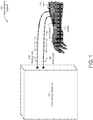
- FIG. 1 illustrates an example hemodialysis system 100 to purify the blood of a patient.
- the hemodialysis system 100 includes a hemodialysis machine 102 that purifies the blood.
- the blood is received by the hemodialysis machine 102 from the patient via an input line 106.
- the input line 106 may comprise a tube attached to a needle that may be inserted into the vascular access (e.g., the vein 108) of the patient.
- a high access blood flow (ABF) may be required.
- a physician may increase the ABF in the vein 108 by surgically creating an arterio-venous (AV) fistula 110 by connecting an artery 112 to the vein 108. Thereby, the blood from the artery 112 may directly flow into the vein 108.
- the increased ABF in the vein 108 caused by the AV fistula 110 may increase the blood flow in input line 106 to the hemodialysis machine 102.
- the output line 104 may comprise a tube connected to a needle that may be inserted into the patient.
- the AV fistula 110 that provides the high ABF for the dialysis machine may have various complications.
- a clot may form inside the AV fistula 110, the vein 108, and/or the artery 112 and reduce the ABF in the vein 108.
- These complications may be mitigated by monitoring the ABF of the patient and/or predicting thrombosis (e.g., clot formation blocking blood flow) as described in more detail below. Predicting thrombosis may allow a physician to take pre-emptive action, including but not limited to repairing the AV fistula, early in the formation of the complication and thereby prolong the functional life of mature AV fistulas.
- FIG. 2 provides an example non-invasive method of monitoring access blood flow in a patient using video image processing.
- the method 200 captures and analyzes images of the small motion of an area of interest (e.g., an AV fistula) to identify various access blood flow characteristics of the patient.
- an area of interest e.g., an AV fistula
- the access blood flow characteristics may include, for example, the ABF of the patient and/or the likelihood of the patient developing thrombosis.
- a system such as the system described above, captures a video recording of an area of interest on the patient.
- the system may capture video of an AV fistula of the patient, although other areas of interest are possible.
- the video may be captured while the patient is undergoing hemodialysis treatment or while the patient is in a static state (i.e., not currently undergoing hemodialysis treatment).
- the video recording of the area of interest on the patient may be taken by any of a variety of medical imaging systems as described in more detail below with reference to FIG. 3 .
- the medical imaging systems may be specifically constructed to take images of an AV fistula of a hemodialysis patient as illustrated in FIG. 4 . These specifically constructed medical imaging systems may control the light surrounding the AV fistula to, for example, improve the quality of the captured video.
- the motion in the captured video recording is amplified.
- the motion exhibited by the skin based on various fluid dynamics beneath the skin may be very small.
- amplifying the small motion exhibited by the skin better enables delineation between noise and motion in the video that is attributable to the movement of the skin.
- Any of a variety of methods may be employed to amplify the motion in the captured video.
- Example motion amplifications processes are described in more detail below with reference to the Example Motion Amplification section.
- the amplitude of the motion (e.g., optic flow) is determined. Quantifying the motion in the video enables the identification of patterns and/or particular characteristics of the motion.
- the amplitude may be determined by, for example, determining the intensity changes of each pixel between consecutive frames. Assuming the camera is fixed and the background is relatively constant, the pixels exhibiting color and/or intensity changes between images frames are generally capturing motion of the patient. These pixels may be assessed in the video stream to determine the degree of the motion present in the video stream.
- FIGS. 5A-5C Various example processes to determine the amplitude of the motion are described in more detail below with references to FIGS. 5A-5C .
- access blood flow characteristics of the patient are determined based on the quantified amplitude of motion in the video stream.
- the access blood flow characteristics may be determined based on analyzing the amplitude of motion in the time domain and/or the frequency domain.
- the ABF of a hemodialysis patient may be determined by calculating an average amplitude of the motion in the video stream and applying the determined average amplitude to a model as described in more detail with reference to FIG. 6 .
- the amplitude of the motion may be transformed into the frequency domain for analysis to, for example, predict the onset of thrombosis as described in more detail below with reference to FIG. 7 .
- the method of monitoring access blood flow 200 may be performed on a variety of systems depending upon the particular implementation.
- the method may be performed by a medical imaging system that also captures video of the area of interest on the patient and/or performed on a computer system in communication with the medical imaging system as described in more detail below.
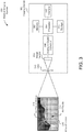
- FIG. 3 illustrates an example medical imaging system that may capture video of an area of interest on a patient.
- the medical imaging system 300 includes an imaging device 302 that is configured to provide digital images and/or video frames of an area of interest 320 on a patient including, for example, an AV fistula 110.
- the sequence of frames in the video capture motion by the skin in the area of interest as illustrated by the AV fistula motion 318.
- the video may be captured by the imaging device 102 at a standard frame rate such as, for example, 30 frames per second (FPS).
- the frame rate may be adjusted based on the anticipated frequency of the motion to be analyzed. For example, the frequency of the motion may be in the 0.5 to 10 Hertz (Hz) range and the frame rate may be selected to be at least double the highest frequency (i.e., 20 FPS).
- Hz Hertz
- the imaging device 302 includes a processor 304 in communication with other components in the imaging device 302 to enable the acquisition of images and the organization of images into a video stream.
- the processor 304 may also perform one or more acts of the method 200 of monitoring access blood flow in the patient.
- the processor 304 may be configured to amplify the motion in the captured video consistent with act 204, determine the amplitude of motion in the video consistent with act 206, and/or identify access blood flow characteristics consistent with act 208.
- the processor 304 may be any type of processor, multiprocessor or controller including, for example, a digital signal processor (DSP).
- DSP digital signal processor
- the processor 304 may be connected to a data storage element 312 that includes a writeable nonvolatile, or non-transitory, data storage medium in which instructions are stored that define a program, component, or other object that is executed by the processor 304.
- a memory 308 may also be coupled to the processor 304 to store programs and data during operation of the imaging device 302.
- the memory 308 may be a relatively high performance, volatile, random access memory such as a dynamic random access memory (“DRAM”) or static memory (“SRAM").
- DRAM dynamic random access memory
- SRAM static memory
- the imaging device 302 may include one or more interface devices 310 connected to the processor 304 such as input devices, output devices, and combination input/output devices. These interface devices 310 may include various devices to display images and/or video to a user (e.g., a physician) and enable the user to control one or more aspects of the imaging system 300.
- the interface 310 may include a user interface that is operable by a physician to control an aperture of the imaging device 302 and/or an orientation of the imaging device 302 relative to the area of interest 320.
- Example interface devices include microphones, touch screens, display screens, speakers, buttons, and keypads. It is appreciated that the interface devices 310 may also enable the processor 304 to communicate with external systems and/or devices.
- the lens 316 includes one or more lenses that focus the visible radiation on the image sensor 314. It is appreciated that the lens 316 is not limited to a single physical lens as illustrated in FIG. 3 . In some examples, the lens 316 includes a plurality of zoom lenses that enable optical zoom. Optical zoom may be accomplished by narrowing the field of view of the visible radiation incident on the image sensor 314.
- the image sensor 314 may include a two-dimensional area of sensors (e.g., photo-detectors) that are sensitive to light.
- the photo-detectors of the image sensor 314 can detect the intensity of the visible radiation in one of two or more individual color and/or brightness components.
- the output of the photo-detectors may include values consistent with a YUV or RGB color space.
- the image sensor 314 may be a monochrome image sensor and only capture light intensity information and not any color information. As described in more detail below, it may be advantageous in some examples to capture monochrome images to omit one or more subsequent image processing steps including, for example, any grayscaling image processing steps.
- the image sensor 314 outputs an analog signal proportional to the intensity and/or color of visible radiation striking the photo-detectors of the image sensor 314.
- the analog signal output by the image sensor 314 may be converted to digital data by the analog-to-digital converter 306 for processing by the processor 304.
- the functionality of the analog-to-digital converter 306 is integrated with the image sensor 314.
- the imaging device 302 is shown by way of example as one type of device upon which various aspects and functions may be practiced, aspects and functions are not limited to being implemented on the imaging device 302 as shown in FIG. 3 . Various aspects and functions may be practiced on imaging devices having a different architectures or components than that shown in FIG. 3 .
- the imaging device 302 may include specially programmed, special-purpose hardware, such as an application-specific integrated circuit ("ASIC") or a system on a chip (“SoC”) tailored to perform a particular operation disclosed herein.
- ASIC application-specific integrated circuit
- SoC system on a chip
- the imaging system 300 may be specifically constructed for the purpose of capturing video of an area of interest on a patient. These dedicated devices may advantageously improve system performance by controlling the lighting of the area of interest and/or properly orientating the imaging sensor 314 and/or lens 316 at an optimum orientation relative to each other and to an area of interest to capture video of the area of interest.
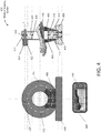
- FIG. 4 Such a uniquely constructed medical imaging device is illustrated in FIG. 4 .
- the medical imaging device 400 illustrated in FIG. 4 is specifically constructed to capture images of an AV fistula on an arm of a hemodialysis patient.
- the medical imaging system 400 provides support for the arm of the patient to encourage the patient to remain still during the imaging process and allows a user (e.g., a physician or a technician) to control an orientation of the imaging sensor.
- the medical imaging system 400 includes a rotating wheel 402 that rotates within a housing 404 having an opening to receive a forearm of the patient including an AV fistula 110.
- the arm of the patient may be supported by arm cushions 406 at both the front and rear sides of the housing 404.
- a light support 420 is mounted and/or integral to the rotating wheel 402 that supports a light source 418.
- the light source 418 may be selected and/or calibrated to provide a known and substantially constant illumination. Alternatively, the light source 418 may be configured to provide a controllable level of illumination. Mounting the light source 418 to the rotating wheel 402 via the light support 420 allows the position of the light source 418 to be changed.
- a physician may adjust a location of the light source 418 to control the lighting on and/or around the AV fistula 110.
- the imaging sensor 412 is supported by an image sensor support 414 that is mounted and/or integral to the rotating wheel 402. Mounting the imaging sensor 412 to the rotating wheel 402 allows a user (e.g., a physician) to move the imaging sensor 412 to image difference regions from difference angles.
- the image sensor support 414 may allow for movement of the imaging sensor 412 in one or more axes, such as along the length of the arm of the patient.
- the image sensor support 414 may further allow for movement of the imaging sensor 412 in a rotational manner, for example, around the patient's arm.
- the medical imaging system 400 may optimize a position of the light source 418 and/or the imaging sensor 412 to capture the highest quality video of the AV fistula 110.
- the location may be optimized so as to yield the largest detected amplitude of motion of the AV fistula 110.
- this orientation is such that the motion of the AV fistula is substantially in the plane captured by the imaging sensor. It has been determined, for example, that the medical imaging system 400 may provide optimal results when the imaging sensor 412 is at a position approximately 30 centimeters away from the AV fistula 110, and at an angle capturing a lateral view of the AV fistula 110.
- the housing 404 may be connected to a base 408 by screws 410 to keep the medical imaging system 400 in place on a flat surface (e.g., a table). It is appreciated that other mechanisms may be employed to connect the base 408 to the housing 404.
- the base 408 may be constructed to be integral to the housing 404.
- the rotating wheel 402 may be turned by a variety of mechanisms.
- the rotating wheel 402 may be connected to a driving gear 426 that is powered by a motor 422 via a driving axle 424.
- the motor 422 may be, for example, a stepper motor that receives instructions from another device.
- the user interface device 428 may include a keypad 430 that may be operated by a user (e.g., a physician) to control the rotation of the rotating wheel 402.
- the user can view the current position of the imaging sensor 412 on a display integrated into the user interface device 428.
- the user interface device 428 may take a variety of forms and may be integral to the medical imaging system 400 or in wireless communication with the medical imaging system 400.
- the user interface device 428 may be a smartphone, tablet, or computer in wireless communication with the medical imaging system 400.
- various medical imaging systems may be constructed in a variety of forms based on, for example, the particular area of interest being imaged. Further, any of these medical imaging systems may perform one or more additional functions separate from capturing video of the area of interest as described above. For example, the medical imaging systems may amplify the motion in the captured video consistent with act 204 of the blood flow monitoring process 200.
- the motion exhibited by, for example, an AV fistula may be difficult (or impossible) to see with a human eye from raw image data. These small motions may be amplified to increase the scale of the motion to simplify the delineation between noise and movement in the video.
- the motion amplification may be achieved by, for example, performing eulerian video magnification on the captured video. Eulerian video magnification combines spatial and temporal processing to amplify subtle motion in the video.
- the video sequence is decomposed into different spatial frequency bands using a Lapancian pyramid.
- temporal filters may be applied to select frequencies of interest within the spatially decomposed frequency bands.
- the frequencies of interest may include, for example, a range surrounding the normal heart rate of a human.
- the selected frequencies of interest may be amplified and recombined with the respective spatial frequency bands. Thereby, motion within the frequencies of interest is amplified. These spatial frequency bands may be recombined to form a new motion amplified video. Additional examples regarding eulerian video magnification are provided in U.S. Patent Application Publication No. 2014/0072190 titled "LINEAR-BASED EULERIAN MOTION MODULATION,” published on March 13, 2014.
- one or more processes may be employed to crop the video to remove areas in the video frames that are not exhibiting any motion (e.g., background) to, for example, reduce the computational complexity of the subsequent quantification of the motion in the video as described below.
- the amplified motion in the captured video may be quantified in order to analyze the motion.
- the motion in the images may be quantified by analyzing changes in the intensity of light between successive frames in an image.
- the intensity of light should be relatively constant at all areas not exhibiting any motion (e.g., a floor in the background of a video).
- the areas with motion in the video exhibit changes in intensity as the pixels change from illustrating the background to illustrating the skin of the patient.
- the AV fistula may be imaged against a still backdrop (e.g., a hospital floor or wall).
- Process 500A in FIG. 5A illustrates such an example method of quantifying the motion.
- the motion amplified video is grayscaled to, for example, combine the plurality of color channels of the video frames into a single luminance channel.
- Any of a variety of methods may be employed to grayscale the motion amplified video as is known by those skilled in the art.
- the motion amplified video may be grayscaled by taking a weighted average of the various color channels (e.g., R, G, and B channels). It is appreciated that act 502 may be omitted in certain circumstances, for example, applications where the video recording is taken with a monochrome imager as illustrated by process 500B in FIG. 5B .
- the motion amplified and grayscaled video is converted to a binary video with each pixel being either black or white.
- the grayscaled video may be converted to binary by, for example, applying a threshold to each pixel in the frames.
- each pixel value in the grayscaled video may be an 8-bit value between 0 and 255 representing an intensity between white (e.g., 0) and black (e.g., 255).
- a threshold of 125 may be applied that converts all of the pixels with a value above 125 to black and converts all pixels with a value below 125 to white.
- the threshold applied to the grayscaled video may be, for example, a preprogrammed value and/or determined dynamically by the system.
- the system may analyze a tonal distribution of the successive frames to identify a particular threshold. It is appreciated that a color image may be directly converted into a binary image and, in some examples, the intermediary step of grayscaling the image may be omitted as illustrated by process 500B in FIG. 5B .
- the system determines the intensity changes between successive frames in the binary video.
- the intensity changes may be determined by identifying a difference in intensity values between each respective pixel in successive frames and summing the differences.
- the difference in intensity I at each respective pixel location may be determined.
- the pixel location (3, 4) may have a value of 0 in a first frame and have a value of 1 in a second subsequent frame thereby yielding a difference of 1.
- each element in the array may be a sum of the differences between respective pixel values in two successive frames.
- equation (3) An example equation illustrating the summation of intensity changes across entire frames is illustrated by equation (3) below.
- the array of intensity changes may be represented as a time function.
- the units of the time function of intensity changes may be converted based on the particular implementation. For example, the time function may be converted from changing pixels per consecutive frame pair to millimeters of displacement of the skin.
- the determination of intensity changes performed in act 506 does not need to be performed on a binary video stream.
- the determination of intensity changes described above may also be readily applied to, for example, a grayscaled video stream as illustrated by process 500C in FIG. 5C .
- the intensity differences determined for a given pixel in two successive frames may shift from a first range of -1 to 1 in the case of binary video stream to a second range of -255 to 255 for 8-bit grayscaled video stream.
- the quantified amplitude of motion in successive frames of the captured video may be analyzed to determine various blood flow characteristics of the patient. These blood flow characteristics may be determined based on various patterns in the amplitude of motion exhibited by patients with low and high ABFs. For example, the ABF of the patient may be estimated by determining the average amplitude of the motion as illustrated by process 600 in FIG. 6 .
- the quantified amplitude of motion may be filtered to remove excess noise.
- the motion of interest may have a limited possible range of frequency values. Accordingly, signal components with frequency values above the range of interest are likely noise and may be excluded.
- the range of interest may be between 0.02 Hz and 5 Hz and a bandpass filter may be constructed that attenuates signal components below 0.02 Hz and above 5 Hz. It is appreciated that the bandpass filter may be implemented in a variety of fashions as is known to those skilled in the art.
- the average amplitude of the motion over a time duration may be determined.
- the averaged amplitude over the time duration may be used to determine an estimate of ABF in the patient.
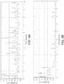
- FIG. 9A showing the amplitude of motion for a patient with a high ABF
- FIG. 9B illustrating the amplitude of motion for a patient with a low ABF
- the amplitude of motion in the high ABF patient is generally much higher over the ten second period than the patient with the low ABF.
- FIG. 10A illustrates the amplitude of motion for a patient with a low ABF after intervention by a physician to improve the blood flow
- FIG. 10B illustrates the amplitude of motion of the same patient before physician intervention.
- the average amplitude of the motion generally increased after the physician intervened and blood flow improved.
- an estimate of the ABF may be determined by applying a linear (or non-linear) model to the averaged amplitude of motion over the time duration.
- the coefficient A and the constant B may be determined based on, for example, a linear regression analysis of experimental data obtained from a set of patients.
- the coefficient A and the constant B also could be the functions of patients' physiological parameters, for example A and B could be associated with body composition (e.g., fat and muscle), weight, height and gender.
- FIG. 8 illustrates an example graph illustrating the relationship between the average amplitude over a ten second period with the ABF measured with conventional techniques (e.g., by online-clearance monitoring).
- a model 802 may be derived from the set of data to illustrate the relationship between average amplitude and estimated ABF. In the graph illustrated in FIG.
- the model 802 has a coefficient A equal to 19666 and a constant B equal to 319.21.
- the model may be implemented as, for example, a look-up table that correlates average amplitude to ABF.
- Other models separate from the linear model illustrated in equation (4) may be employed including, for example, various non-linear models.
- the amplitude of motion may be employed to predict thrombosis in the patient as illustrated by FIG. 7 .
- the thrombosis prediction process 700 employs the frequency domain representation of the amplitude of motion to identify various patterns.
- a Fourier transform is applied to the time function of the amplitude of motion.
- Various methods may be employed to transform the time function of the amplitude of motion from the time-domain to the frequency domain including various approximation techniques as is appreciated by those skilled in the art.
- FFT fast Fourier transform
- a fast Fourier transform may be employed to transform the time function to the frequency domain.
- the frequency composition of the amplitude of motion is analyzed. For example, the location of the peaks in the frequency domain representation of the amplitude of motion may be identified and compared to one or more threshold ranges.
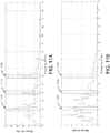
- FIGS. 11A and 11B illustrate the comparison between a patient with low ABF before and after physician intervention to improve blood flow. More specifically, FIG. 11A illustrates the frequency domain representation of the amplitude of motion after physician intervention and FIG. 11B illustrates the frequency domain representation of the amplitude of motion before physician intervention. As illustrated by regions 1102, 1104, and 1106, the frequency domain representation of the amplitude of motion of the patient post-intervention has peaks around 2 Hz, 4 Hz, and 6 Hz.
- the frequency domain representation does not exhibit the same definitive peaks around 2 Hz, 4 Hz, and 6 Hz.
- This pattern may be employed to predict and/or identify thrombosis in the patient.
- the patient may be predicted to develop thrombosis if the highest peaks in the frequency domain representation of the average amplitude are below the 2 Hz, 4 Hz, and 6 Hz ranges illustrated in FIGS. 11A and 11B .
- aspects and examples provide non-invasive procedures by which to analyze ABF in hemodialysis patients and/or predict potential physiological abnormalities, such as thrombosis, for example.
- various alterations, modifications, and improvements will readily occur to those skilled in the art. Such alterations, modifications, and improvements are intended to be part of this disclosure.
Landscapes
- Health & Medical Sciences (AREA)
- Engineering & Computer Science (AREA)
- Life Sciences & Earth Sciences (AREA)
- Heart & Thoracic Surgery (AREA)
- General Health & Medical Sciences (AREA)
- Physics & Mathematics (AREA)
- Animal Behavior & Ethology (AREA)
- Veterinary Medicine (AREA)
- Public Health (AREA)
- Biomedical Technology (AREA)
- Medical Informatics (AREA)
- Pathology (AREA)
- Surgery (AREA)
- Molecular Biology (AREA)
- Biophysics (AREA)
- Computer Vision & Pattern Recognition (AREA)
- General Physics & Mathematics (AREA)
- Theoretical Computer Science (AREA)
- Hematology (AREA)
- Vascular Medicine (AREA)
- Cardiology (AREA)
- Anesthesiology (AREA)
- Multimedia (AREA)
- Nuclear Medicine, Radiotherapy & Molecular Imaging (AREA)
- Radiology & Medical Imaging (AREA)
- Quality & Reliability (AREA)
- Physiology (AREA)
- Physical Education & Sports Medicine (AREA)
- Emergency Medicine (AREA)
- Urology & Nephrology (AREA)
- External Artificial Organs (AREA)
- Measuring Pulse, Heart Rate, Blood Pressure Or Blood Flow (AREA)
- Measurement Of The Respiration, Hearing Ability, Form, And Blood Characteristics Of Living Organisms (AREA)
Claims (11)
- Medizinische Abbildungsvorrichtung (400) zur Abbildung einer arteriovenösen, AV, Fistel (110) eines Hämodialysepatienten, umfassend:ein Gehäuse (404), das eine sich dort hindurch erstreckende Öffnung aufweist, wobei die Öffnung bemessen ist, um einen Arm des Hämodialysepatienten aufzunehmen;eine Armstütze (406), die dazu konfiguriert ist, den Arm des Hämodialysepatienten zu stützen, wenn der Arm sich durch die Öffnung in dem Gehäuse (404) erstreckt;ein sich drehendes Rad (402), das innerhalb des Gehäuses (404) angeordnet ist und dazu konfiguriert ist, sich um die Öffnung zu drehen;eine Lichtquelle (418), die innerhalb des Gehäuses an dem sich drehenden Rad (402) angeordnet ist, wobei die Lichtquelle (418) dazu konfiguriert ist, mindestens einen Teil des Arms, der sich innerhalb der Öffnung befindet, zu beleuchten, wobei der Teil des Arms die AV Fistel (110) beinhaltet; undeinen Abbildungssensor (412), der innerhalb des Gehäuses (404) an dem sich drehenden Rad (402) angeordnet ist und dazu konfiguriert ist, Videobilder der AV Fistel (110) zu produzieren.
- Medizinische Abbildungsvorrichtung nach Anspruch 1, wobei der Abbildungssensor (412) weiterhin dazu konfiguriert ist, eine erste Zeitreihe von Videobildern der arteriovenösen Fistel (110) zu beziehen, wobei die medizinische Abbildungsvorrichtung (400) weiterhin umfasst:eine Videoverarbeitungsanordnung, die an den Abbildungssensor (412) gekoppelt ist und dazu konfiguriert ist, die erste Zeitreihe von Videobildern zu empfangen und zu verarbeiten, beinhaltend:Durchführen eines Bewegungsverstärkungsvorgangs an jedem Videobild in der ersten Zeitreihe von Videobildern, um eine zweite Zeitreihe von bewegungsverstärkten Videobildern zu produzieren;Umwandeln der zweiten Zeitreihe von bewegungsverstärkten Videobildern in eine dritte Zeitreihe von Amplituden eines optischen Flusses auf der Basis von Veränderungen der Intensität zwischen aufeinanderfolgenden bewegungsverstärkten Videobildern in der zweiten Zeitreihe von bewegungsverstärkten Videobildern undProduzieren eines Schätzwerts des physiologischen Parameters zumindest zum Teil auf der Basis der dritten Zeitreihe von Amplituden des optischen Flusses; undeine Anzeige, die an die Videoverarbeitungsanordnung gekoppelt ist und dazu konfiguriert ist, mindestens einen bzw. eine von dem Schätzwert des physiologischen Parameters und der zweiten Zeitreihe von bewegungsverstärkten Videobildern anzuzeigen.
- Medizinische Abbildungsvorrichtung nach Anspruch 1, weiterhin umfassend einen Controller, der konfiguriert ist zum:Steuern einer Drehung des sich drehenden Rads (402) auf der Basis einer Amplitude einer abgebildeten Bewegung in der AV Fistel (110) undDrehen des sich drehenden Rads (402), um den Abbildungssensor (412) neu zu positionieren, um die Amplitude der abgebildeten Bewegung zu maximieren.
- Medizinische Abbildungsvorrichtung nach Anspruch 3, weiterhin umfassend eine Antriebsanordnung, die an das sich drehende Rad (402) gekoppelt ist und dazu konfiguriert ist, eine Drehung des sich drehenden Rads (402) um die Öffnung anzutreiben, wobei die Antriebsanordnung eine Antriebsachse (424), die an das sich drehende Rad (402) gekoppelt ist, und einen Schrittmotor (422), der an die Antriebsachse (424) gekoppelt ist, beinhaltet.
- Medizinische Abbildungsvorrichtung nach Anspruch 3, weiterhin umfassend eine Anzeige, und wobei der Controller und die Anzeige in eine tragbare Vorrichtung integriert sind und wobei die tragbare Vorrichtung mindestens eines bzw. einen von einem Mobiltelefon oder einem Tablet-Computer beinhaltet.
- Medizinische Abbildungsvorrichtung nach Anspruch 3, wobei der Controller dazu konfiguriert ist, die Drehung des sich drehenden Rads (402) als Reaktion auf eine von einem Benutzer empfangene Anweisung zu steuern.
- Medizinische Abbildungsvorrichtung nach Anspruch 1, wobei die Lichtquelle (418) eine konstante Helligkeit aufrechterhält, während der Abbildungssensor (412) die Videobilder der AV Fistel produziert.
- Medizinische Abbildungsvorrichtung nach Anspruch 1, wobei die Lichtquelle (418) eine konfigurierbare Helligkeit aufweist.
- Medizinische Abbildungsvorrichtung nach Anspruch 1, wobei die Öffnung eine im Wesentlichen runde Form aufweist und wobei das Gehäuse (404) ein im Wesentlichen rundes Gehäuse ist und die Öffnung zentral innerhalb des im Wesentlichen runden Gehäuses angeordnet ist.
- Medizinische Abbildungsvorrichtung nach Anspruch 2, wobei der physiologische Parameter mindestens einen bzw. eine von einem Schätzwert eines Zugangsblutflusses und einer Vorhersage, ob der Patient eine Thrombose entwickeln wird, beinhaltet.
- Medizinische Abbildungsvorrichtung nach Anspruch 1, weiterhin umfassend ein Bewegungssteuersystem, das dazu konfiguriert ist, den Abbildungssensor (412) in einer Richtung einer orthogonalen sich drehenden Bereichs zu bewegen.
Priority Applications (1)
| Application Number | Priority Date | Filing Date | Title |
|---|---|---|---|
| EP20216434.9A EP3834714A1 (de) | 2015-11-03 | 2016-11-01 | Verfahren und vorrichtung zur beurteilung des zugangsflusses bei hämodialysepatienten durch videobildverarbeitung |
Applications Claiming Priority (2)
| Application Number | Priority Date | Filing Date | Title |
|---|---|---|---|
| US201562250294P | 2015-11-03 | 2015-11-03 | |
| PCT/US2016/059885 WO2017079142A1 (en) | 2015-11-03 | 2016-11-01 | Method and apparatus of assessment of access flow in hemodialysis patients by video imaging processing |
Related Child Applications (2)
| Application Number | Title | Priority Date | Filing Date |
|---|---|---|---|
| EP20216434.9A Division-Into EP3834714A1 (de) | 2015-11-03 | 2016-11-01 | Verfahren und vorrichtung zur beurteilung des zugangsflusses bei hämodialysepatienten durch videobildverarbeitung |
| EP20216434.9A Division EP3834714A1 (de) | 2015-11-03 | 2016-11-01 | Verfahren und vorrichtung zur beurteilung des zugangsflusses bei hämodialysepatienten durch videobildverarbeitung |
Publications (3)
| Publication Number | Publication Date |
|---|---|
| EP3370609A1 EP3370609A1 (de) | 2018-09-12 |
| EP3370609A4 EP3370609A4 (de) | 2019-10-16 |
| EP3370609B1 true EP3370609B1 (de) | 2021-03-31 |
Family
ID=58637753
Family Applications (2)
| Application Number | Title | Priority Date | Filing Date |
|---|---|---|---|
| EP20216434.9A Pending EP3834714A1 (de) | 2015-11-03 | 2016-11-01 | Verfahren und vorrichtung zur beurteilung des zugangsflusses bei hämodialysepatienten durch videobildverarbeitung |
| EP16862787.5A Active EP3370609B1 (de) | 2015-11-03 | 2016-11-01 | Verfahren und vorrichtung zur beurteilung des zugangsflusses bei hämodialysepatienten durch videobildverarbeitung |
Family Applications Before (1)
| Application Number | Title | Priority Date | Filing Date |
|---|---|---|---|
| EP20216434.9A Pending EP3834714A1 (de) | 2015-11-03 | 2016-11-01 | Verfahren und vorrichtung zur beurteilung des zugangsflusses bei hämodialysepatienten durch videobildverarbeitung |
Country Status (6)
| Country | Link |
|---|---|
| US (2) | US9993169B2 (de) |
| EP (2) | EP3834714A1 (de) |
| CN (1) | CN108348179B (de) |
| AU (2) | AU2016348404B2 (de) |
| CA (1) | CA3001622A1 (de) |
| WO (1) | WO2017079142A1 (de) |
Families Citing this family (31)
| Publication number | Priority date | Publication date | Assignee | Title |
|---|---|---|---|---|
| US12048469B2 (en) | 2013-03-04 | 2024-07-30 | Csa Medical, Inc. | Cryospray catheters |
| CA2951050A1 (en) | 2014-06-04 | 2015-12-10 | Csa Medical, Inc. | Method and system for consistent, repeatable, and safe cryospray treatment of airway tissue |
| US12300273B2 (en) | 2014-12-11 | 2025-05-13 | Rdi Technologies, Inc. | Apparatus and method for visualizing periodic motions in mechanical components |
| US10459615B2 (en) | 2014-12-11 | 2019-10-29 | Rdi Technologies, Inc. | Apparatus and method for analyzing periodic motions in machinery |
| US10062411B2 (en) | 2014-12-11 | 2018-08-28 | Jeffrey R. Hay | Apparatus and method for visualizing periodic motions in mechanical components |
| WO2018210692A1 (en) | 2017-05-15 | 2018-11-22 | Smith & Nephew Plc | Wound analysis device and method |
| AU2018269113A1 (en) * | 2017-05-15 | 2019-11-21 | Smith & Nephew Plc | Negative pressure wound therapy system using eulerian video magnification |
| WO2019032706A1 (en) * | 2017-08-10 | 2019-02-14 | Riaan Conradie | USER VERIFICATION BY COMPARISON OF PHYSIOLOGICAL SENSOR DATA WITH PHYSIOLOGICAL DATA DERIVED FROM FACIAL VIDEO |
| US10878966B2 (en) * | 2017-08-13 | 2020-12-29 | Theator inc. | System and method for analysis and presentation of surgical procedure videos |
| US11116587B2 (en) | 2018-08-13 | 2021-09-14 | Theator inc. | Timeline overlay on surgical video |
| WO2020037127A1 (en) * | 2018-08-17 | 2020-02-20 | Dauntless.Io, Inc. | Systems and methods for modeling and controlling physical dynamical systems using artificial intelligence |
| US11423551B1 (en) * | 2018-10-17 | 2022-08-23 | Rdi Technologies, Inc. | Enhanced presentation methods for visualizing motion of physical structures and machinery |
| US20210015991A1 (en) * | 2018-10-19 | 2021-01-21 | PatenSee Ltd. | Systems and methods for monitoring the functionality of a blood vessel |
| KR102694422B1 (ko) | 2019-02-21 | 2024-08-14 | 시어터 인코포레이티드 | 수술 비디오의 분석을 위한 시스템 및 방법 |
| US20200273563A1 (en) | 2019-02-21 | 2020-08-27 | Theator inc. | Adjusting an operating room schedule |
| ES3036845T3 (en) * | 2019-03-27 | 2025-09-24 | William E Butler | Reconstructing cardiac frequency phenomena in angiographic data |
| US12543960B2 (en) * | 2019-10-18 | 2026-02-10 | PatenSee Ltd. | Systems and methods for monitoring the functionality of a blood vessel |
| US20210142882A1 (en) * | 2019-11-08 | 2021-05-13 | Fresenius Medical Care Holdings, Inc. | Techniques for image-based examination of dialysis access sites |
| US11607145B2 (en) | 2019-11-08 | 2023-03-21 | Fresenius Medical Care Holdings, Inc. | Techniques for determining characteristics of dialysis access sites using image information |
| US11373317B1 (en) | 2020-01-24 | 2022-06-28 | Rdi Technologies, Inc. | Measuring the speed of rotation or reciprocation of a mechanical component using one or more cameras |
| US11227686B2 (en) | 2020-04-05 | 2022-01-18 | Theator inc. | Systems and methods for processing integrated surgical video collections to identify relationships using artificial intelligence |
| CN111426284B (zh) * | 2020-04-10 | 2021-10-19 | 山东师范大学 | 基于Brox光流估计的面形测量误差校正方法及系统 |
| US11338072B2 (en) * | 2020-04-14 | 2022-05-24 | Fresenius Medical Care Holdings, Inc. | Blood treatment systems and related components and methods |
| US11742080B2 (en) * | 2020-06-10 | 2023-08-29 | Fresenius Medical Care Holdings, Inc. | Secure artificial intelligence enabled wearable medical sensor platforms |
| US11282213B1 (en) | 2020-06-24 | 2022-03-22 | Rdi Technologies, Inc. | Enhanced analysis techniques using composite frequency spectrum data |
| US11322182B1 (en) | 2020-09-28 | 2022-05-03 | Rdi Technologies, Inc. | Enhanced visualization techniques using reconstructed time waveforms |
| WO2022076776A1 (en) | 2020-10-08 | 2022-04-14 | Fresenius Medical Care Holdings, Inc. | Techniques for determining characteristics of dialysis access sites using image information |
| CN114648629B (zh) * | 2020-12-18 | 2025-02-11 | 重庆中星微人工智能芯片技术有限公司 | 感兴趣区域生成方法、装置、设备和计算机可读介质 |
| US20230385948A1 (en) | 2022-05-30 | 2023-11-30 | Theator inc. | Correlating a medical claim code with a portion of a video |
| CN119344773B (zh) * | 2024-12-26 | 2025-03-21 | 浙江大学 | 基于光流分析的肌骨超声超微血流量化分级方法与系统 |
| CN120267914B (zh) * | 2025-06-12 | 2026-01-09 | 四川大学华西医院 | 一种涡流式静脉壶凝血预警方法和系统 |
Family Cites Families (14)
| Publication number | Priority date | Publication date | Assignee | Title |
|---|---|---|---|---|
| DE60045880D1 (de) * | 1999-09-24 | 2011-06-01 | Nat Res Council Of Canada Ottawa | Vorrichtung zur Durchführung einer intraoperativen Angiographie |
| WO2002026118A2 (en) | 2000-09-29 | 2002-04-04 | New Health Sciences, Inc. | Systems and methods for assessing vascular effects of a treatment |
| US6746407B2 (en) * | 2000-12-29 | 2004-06-08 | Hema Metrics, Inc. | Method of measuring transcutaneous access blood flow |
| US20060077286A1 (en) | 2004-10-08 | 2006-04-13 | Wenderski Gregory J | Video camera support assembly |
| DE102005018327A1 (de) * | 2005-04-20 | 2006-10-26 | Siemens Ag | Betriebsverfahren für einen Rechner, Betriebsverfahren für eine bildgebende medizintechnische Anlage und hiermit korrespondierende Gegenstände |
| JP4915726B2 (ja) * | 2006-07-12 | 2012-04-11 | 株式会社イメージワン | 血流速度の測定方法及び装置 |
| US7995816B2 (en) * | 2007-09-24 | 2011-08-09 | Baxter International Inc. | Detecting access disconnect by pattern recognition |
| US9320437B2 (en) * | 2009-12-22 | 2016-04-26 | Genial Light Co., Ltd. | Intravital observation device |
| DE102010049723A1 (de) * | 2010-10-26 | 2012-04-26 | Bernhard Ehni | Sicherungseinrichtung zur Kontrolle eines in eine Blutbahn eingeführten Injektionskörpers |
| FI20115053A0 (fi) | 2011-01-19 | 2011-01-19 | Delfin Technologies Oy | Menetelmä ja järjestelmä kardiovaskulaaristen sykeaaltojen visualisoimiseksi |
| US9811901B2 (en) | 2012-09-07 | 2017-11-07 | Massachusetts Institute Of Technology | Linear-based Eulerian motion modulation |
| CN103006195B (zh) * | 2013-01-10 | 2015-06-17 | 浙江大学 | 一种基于图像处理的非接触式生命体征数据监测系统和监测方法 |
| WO2014186611A2 (en) * | 2013-05-15 | 2014-11-20 | Massachusetts Institute Of Technology | Refractive flow measurement system |
| US10638942B2 (en) * | 2013-06-26 | 2020-05-05 | Massachusetts Institute Of Technology | Pulse detection from head motions in video |
-
2016
- 2016-11-01 WO PCT/US2016/059885 patent/WO2017079142A1/en not_active Ceased
- 2016-11-01 EP EP20216434.9A patent/EP3834714A1/de active Pending
- 2016-11-01 CA CA3001622A patent/CA3001622A1/en active Pending
- 2016-11-01 EP EP16862787.5A patent/EP3370609B1/de active Active
- 2016-11-01 AU AU2016348404A patent/AU2016348404B2/en active Active
- 2016-11-01 CN CN201680064224.6A patent/CN108348179B/zh active Active
- 2016-11-01 US US15/340,490 patent/US9993169B2/en active Active
-
2018
- 2018-04-18 US US15/956,086 patent/US10258245B2/en active Active
-
2020
- 2020-09-30 AU AU2020244521A patent/AU2020244521B2/en active Active
Non-Patent Citations (1)
| Title |
|---|
| None * |
Also Published As
| Publication number | Publication date |
|---|---|
| US10258245B2 (en) | 2019-04-16 |
| AU2020244521B2 (en) | 2021-11-11 |
| EP3370609A4 (de) | 2019-10-16 |
| US20170119258A1 (en) | 2017-05-04 |
| CA3001622A1 (en) | 2017-05-11 |
| WO2017079142A1 (en) | 2017-05-11 |
| EP3370609A1 (de) | 2018-09-12 |
| US9993169B2 (en) | 2018-06-12 |
| AU2016348404A1 (en) | 2018-05-10 |
| CN108348179B (zh) | 2021-04-13 |
| CN108348179A (zh) | 2018-07-31 |
| AU2020244521A1 (en) | 2020-10-29 |
| EP3834714A1 (de) | 2021-06-16 |
| US20180228382A1 (en) | 2018-08-16 |
| AU2016348404B2 (en) | 2020-10-22 |
Similar Documents
| Publication | Publication Date | Title |
|---|---|---|
| EP3370609B1 (de) | Verfahren und vorrichtung zur beurteilung des zugangsflusses bei hämodialysepatienten durch videobildverarbeitung | |
| US11800990B2 (en) | Perfusion assessment using transmission laser speckle imaging | |
| Wu et al. | Photoplethysmography imaging: a new noninvasive and noncontact method for mapping of the dermal perfusion changes | |
| CN107106017B (zh) | 用于提取生理信息的设备、系统和方法 | |
| JP6530239B2 (ja) | 両眼計測装置、両眼計測方法、及び両眼計測プログラム | |
| US10159418B2 (en) | Information obtaining apparatus, image capturing apparatus, and method for obtaining information | |
| JPWO2014136310A1 (ja) | 脈波伝播速度の測定方法、その測定方法を用いた測定システムの作動方法及び脈波伝播速度の測定システム並びに撮像装置 | |
| JP2022552570A (ja) | 血管機能を監視するためのシステム及び方法 | |
| CA3023735C (en) | High resolution blood perfusion imaging using a camera and a pulse oximeter | |
| US8315354B2 (en) | Dynamic radiographing system | |
| JP6771968B2 (ja) | 情報取得装置、撮影装置及び情報取得方法 | |
| JP2009136573A (ja) | 動態撮影システム | |
| Zhu et al. | Estimation of arterio-venous access blood flow in hemodialysis patients using video image processing technique | |
| CN113951816B (zh) | 基于光学视频信号分析的无创血管功能检测装置 | |
| JP2017202267A (ja) | 情報取得装置、撮影装置及び情報取得方法 | |
| JP7314893B2 (ja) | 電子装置、電子装置の制御プログラム及び電子装置の制御方法 | |
| US20250000462A1 (en) | Information processing apparatus, information processing method, information processing system, and storage medium | |
| US20260069756A1 (en) | Systems and methods for monitoring the functionality of a blood vessel | |
| JP2017224061A (ja) | 処理装置、情報取得装置、及び画像処理方法 | |
| KR101522535B1 (ko) | 스마트 폰 기반의 혈관 영상 시스템 | |
| Kamshilin et al. | Intraoperative Monitoring of Cerebral Hemodynamics by Camera-Based Photoplethysmography | |
| SK6737Y1 (sk) | Optické skenovacie zariadenie vertikálnych deformácií chrbtice |
Legal Events
| Date | Code | Title | Description |
|---|---|---|---|
| STAA | Information on the status of an ep patent application or granted ep patent |
Free format text: STATUS: THE INTERNATIONAL PUBLICATION HAS BEEN MADE |
|
| PUAI | Public reference made under article 153(3) epc to a published international application that has entered the european phase |
Free format text: ORIGINAL CODE: 0009012 |
|
| STAA | Information on the status of an ep patent application or granted ep patent |
Free format text: STATUS: REQUEST FOR EXAMINATION WAS MADE |
|
| 17P | Request for examination filed |
Effective date: 20180424 |
|
| AK | Designated contracting states |
Kind code of ref document: A1 Designated state(s): AL AT BE BG CH CY CZ DE DK EE ES FI FR GB GR HR HU IE IS IT LI LT LU LV MC MK MT NL NO PL PT RO RS SE SI SK SM TR |
|
| AX | Request for extension of the european patent |
Extension state: BA ME |
|
| DAV | Request for validation of the european patent (deleted) | ||
| DAX | Request for extension of the european patent (deleted) | ||
| RIC1 | Information provided on ipc code assigned before grant |
Ipc: A61B 5/00 20060101ALI20190527BHEP Ipc: A61B 5/026 20060101ALI20190527BHEP Ipc: G06T 7/00 20170101ALI20190527BHEP Ipc: A61B 5/0215 20060101AFI20190527BHEP Ipc: A61B 5/027 20060101ALI20190527BHEP |
|
| A4 | Supplementary search report drawn up and despatched |
Effective date: 20190913 |
|
| RIC1 | Information provided on ipc code assigned before grant |
Ipc: A61B 5/00 20060101ALI20190910BHEP Ipc: G06T 7/00 20170101ALI20190910BHEP Ipc: A61B 5/027 20060101ALI20190910BHEP Ipc: A61B 5/026 20060101ALI20190910BHEP Ipc: A61B 5/0215 20060101AFI20190910BHEP |
|
| GRAP | Despatch of communication of intention to grant a patent |
Free format text: ORIGINAL CODE: EPIDOSNIGR1 |
|
| STAA | Information on the status of an ep patent application or granted ep patent |
Free format text: STATUS: GRANT OF PATENT IS INTENDED |
|
| INTG | Intention to grant announced |
Effective date: 20201019 |
|
| GRAS | Grant fee paid |
Free format text: ORIGINAL CODE: EPIDOSNIGR3 |
|
| GRAA | (expected) grant |
Free format text: ORIGINAL CODE: 0009210 |
|
| STAA | Information on the status of an ep patent application or granted ep patent |
Free format text: STATUS: THE PATENT HAS BEEN GRANTED |
|
| AK | Designated contracting states |
Kind code of ref document: B1 Designated state(s): AL AT BE BG CH CY CZ DE DK EE ES FI FR GB GR HR HU IE IS IT LI LT LU LV MC MK MT NL NO PL PT RO RS SE SI SK SM TR |
|
| REG | Reference to a national code |
Ref country code: GB Ref legal event code: FG4D Ref country code: CH Ref legal event code: EP |
|
| REG | Reference to a national code |
Ref country code: AT Ref legal event code: REF Ref document number: 1376011 Country of ref document: AT Kind code of ref document: T Effective date: 20210415 |
|
| REG | Reference to a national code |
Ref country code: DE Ref legal event code: R096 Ref document number: 602016055421 Country of ref document: DE |
|
| REG | Reference to a national code |
Ref country code: IE Ref legal event code: FG4D |
|
| REG | Reference to a national code |
Ref country code: SE Ref legal event code: TRGR |
|
| REG | Reference to a national code |
Ref country code: LT Ref legal event code: MG9D |
|
| PG25 | Lapsed in a contracting state [announced via postgrant information from national office to epo] |
Ref country code: FI Free format text: LAPSE BECAUSE OF FAILURE TO SUBMIT A TRANSLATION OF THE DESCRIPTION OR TO PAY THE FEE WITHIN THE PRESCRIBED TIME-LIMIT Effective date: 20210331 Ref country code: HR Free format text: LAPSE BECAUSE OF FAILURE TO SUBMIT A TRANSLATION OF THE DESCRIPTION OR TO PAY THE FEE WITHIN THE PRESCRIBED TIME-LIMIT Effective date: 20210331 Ref country code: NO Free format text: LAPSE BECAUSE OF FAILURE TO SUBMIT A TRANSLATION OF THE DESCRIPTION OR TO PAY THE FEE WITHIN THE PRESCRIBED TIME-LIMIT Effective date: 20210630 Ref country code: BG Free format text: LAPSE BECAUSE OF FAILURE TO SUBMIT A TRANSLATION OF THE DESCRIPTION OR TO PAY THE FEE WITHIN THE PRESCRIBED TIME-LIMIT Effective date: 20210630 |
|
| PG25 | Lapsed in a contracting state [announced via postgrant information from national office to epo] |
Ref country code: RS Free format text: LAPSE BECAUSE OF FAILURE TO SUBMIT A TRANSLATION OF THE DESCRIPTION OR TO PAY THE FEE WITHIN THE PRESCRIBED TIME-LIMIT Effective date: 20210331 Ref country code: LV Free format text: LAPSE BECAUSE OF FAILURE TO SUBMIT A TRANSLATION OF THE DESCRIPTION OR TO PAY THE FEE WITHIN THE PRESCRIBED TIME-LIMIT Effective date: 20210331 |
|
| REG | Reference to a national code |
Ref country code: NL Ref legal event code: MP Effective date: 20210331 |
|
| REG | Reference to a national code |
Ref country code: AT Ref legal event code: MK05 Ref document number: 1376011 Country of ref document: AT Kind code of ref document: T Effective date: 20210331 |
|
| PG25 | Lapsed in a contracting state [announced via postgrant information from national office to epo] |
Ref country code: LT Free format text: LAPSE BECAUSE OF FAILURE TO SUBMIT A TRANSLATION OF THE DESCRIPTION OR TO PAY THE FEE WITHIN THE PRESCRIBED TIME-LIMIT Effective date: 20210331 Ref country code: CZ Free format text: LAPSE BECAUSE OF FAILURE TO SUBMIT A TRANSLATION OF THE DESCRIPTION OR TO PAY THE FEE WITHIN THE PRESCRIBED TIME-LIMIT Effective date: 20210331 Ref country code: EE Free format text: LAPSE BECAUSE OF FAILURE TO SUBMIT A TRANSLATION OF THE DESCRIPTION OR TO PAY THE FEE WITHIN THE PRESCRIBED TIME-LIMIT Effective date: 20210331 Ref country code: AT Free format text: LAPSE BECAUSE OF FAILURE TO SUBMIT A TRANSLATION OF THE DESCRIPTION OR TO PAY THE FEE WITHIN THE PRESCRIBED TIME-LIMIT Effective date: 20210331 Ref country code: NL Free format text: LAPSE BECAUSE OF FAILURE TO SUBMIT A TRANSLATION OF THE DESCRIPTION OR TO PAY THE FEE WITHIN THE PRESCRIBED TIME-LIMIT Effective date: 20210331 Ref country code: SM Free format text: LAPSE BECAUSE OF FAILURE TO SUBMIT A TRANSLATION OF THE DESCRIPTION OR TO PAY THE FEE WITHIN THE PRESCRIBED TIME-LIMIT Effective date: 20210331 |
|
| PG25 | Lapsed in a contracting state [announced via postgrant information from national office to epo] |
Ref country code: IS Free format text: LAPSE BECAUSE OF FAILURE TO SUBMIT A TRANSLATION OF THE DESCRIPTION OR TO PAY THE FEE WITHIN THE PRESCRIBED TIME-LIMIT Effective date: 20210731 Ref country code: PT Free format text: LAPSE BECAUSE OF FAILURE TO SUBMIT A TRANSLATION OF THE DESCRIPTION OR TO PAY THE FEE WITHIN THE PRESCRIBED TIME-LIMIT Effective date: 20210802 Ref country code: PL Free format text: LAPSE BECAUSE OF FAILURE TO SUBMIT A TRANSLATION OF THE DESCRIPTION OR TO PAY THE FEE WITHIN THE PRESCRIBED TIME-LIMIT Effective date: 20210331 Ref country code: RO Free format text: LAPSE BECAUSE OF FAILURE TO SUBMIT A TRANSLATION OF THE DESCRIPTION OR TO PAY THE FEE WITHIN THE PRESCRIBED TIME-LIMIT Effective date: 20210331 Ref country code: SK Free format text: LAPSE BECAUSE OF FAILURE TO SUBMIT A TRANSLATION OF THE DESCRIPTION OR TO PAY THE FEE WITHIN THE PRESCRIBED TIME-LIMIT Effective date: 20210331 |
|
| REG | Reference to a national code |
Ref country code: DE Ref legal event code: R097 Ref document number: 602016055421 Country of ref document: DE |
|
| PG25 | Lapsed in a contracting state [announced via postgrant information from national office to epo] |
Ref country code: DK Free format text: LAPSE BECAUSE OF FAILURE TO SUBMIT A TRANSLATION OF THE DESCRIPTION OR TO PAY THE FEE WITHIN THE PRESCRIBED TIME-LIMIT Effective date: 20210331 Ref country code: AL Free format text: LAPSE BECAUSE OF FAILURE TO SUBMIT A TRANSLATION OF THE DESCRIPTION OR TO PAY THE FEE WITHIN THE PRESCRIBED TIME-LIMIT Effective date: 20210331 Ref country code: ES Free format text: LAPSE BECAUSE OF FAILURE TO SUBMIT A TRANSLATION OF THE DESCRIPTION OR TO PAY THE FEE WITHIN THE PRESCRIBED TIME-LIMIT Effective date: 20210331 |
|
| PLBE | No opposition filed within time limit |
Free format text: ORIGINAL CODE: 0009261 |
|
| STAA | Information on the status of an ep patent application or granted ep patent |
Free format text: STATUS: NO OPPOSITION FILED WITHIN TIME LIMIT |
|
| 26N | No opposition filed |
Effective date: 20220104 |
|
| PG25 | Lapsed in a contracting state [announced via postgrant information from national office to epo] |
Ref country code: IS Free format text: LAPSE BECAUSE OF FAILURE TO SUBMIT A TRANSLATION OF THE DESCRIPTION OR TO PAY THE FEE WITHIN THE PRESCRIBED TIME-LIMIT Effective date: 20210731 |
|
| PG25 | Lapsed in a contracting state [announced via postgrant information from national office to epo] |
Ref country code: MC Free format text: LAPSE BECAUSE OF FAILURE TO SUBMIT A TRANSLATION OF THE DESCRIPTION OR TO PAY THE FEE WITHIN THE PRESCRIBED TIME-LIMIT Effective date: 20210331 |
|
| REG | Reference to a national code |
Ref country code: CH Ref legal event code: PL |
|
| PG25 | Lapsed in a contracting state [announced via postgrant information from national office to epo] |
Ref country code: BE Free format text: LAPSE BECAUSE OF NON-PAYMENT OF DUE FEES Effective date: 20211130 Ref country code: LU Free format text: LAPSE BECAUSE OF NON-PAYMENT OF DUE FEES Effective date: 20211101 |
|
| REG | Reference to a national code |
Ref country code: BE Ref legal event code: MM Effective date: 20211130 |
|
| PG25 | Lapsed in a contracting state [announced via postgrant information from national office to epo] |
Ref country code: IE Free format text: LAPSE BECAUSE OF NON-PAYMENT OF DUE FEES Effective date: 20211101 |
|
| PG25 | Lapsed in a contracting state [announced via postgrant information from national office to epo] |
Ref country code: HU Free format text: LAPSE BECAUSE OF FAILURE TO SUBMIT A TRANSLATION OF THE DESCRIPTION OR TO PAY THE FEE WITHIN THE PRESCRIBED TIME-LIMIT; INVALID AB INITIO Effective date: 20161101 |
|
| PG25 | Lapsed in a contracting state [announced via postgrant information from national office to epo] |
Ref country code: CY Free format text: LAPSE BECAUSE OF FAILURE TO SUBMIT A TRANSLATION OF THE DESCRIPTION OR TO PAY THE FEE WITHIN THE PRESCRIBED TIME-LIMIT Effective date: 20210331 |
|
| P01 | Opt-out of the competence of the unified patent court (upc) registered |
Effective date: 20230602 |
|
| PG25 | Lapsed in a contracting state [announced via postgrant information from national office to epo] |
Ref country code: LI Free format text: LAPSE BECAUSE OF NON-PAYMENT OF DUE FEES Effective date: 20220630 Ref country code: GR Free format text: LAPSE BECAUSE OF FAILURE TO SUBMIT A TRANSLATION OF THE DESCRIPTION OR TO PAY THE FEE WITHIN THE PRESCRIBED TIME-LIMIT Effective date: 20210331 Ref country code: CH Free format text: LAPSE BECAUSE OF NON-PAYMENT OF DUE FEES Effective date: 20220630 |
|
| PG25 | Lapsed in a contracting state [announced via postgrant information from national office to epo] |
Ref country code: MK Free format text: LAPSE BECAUSE OF FAILURE TO SUBMIT A TRANSLATION OF THE DESCRIPTION OR TO PAY THE FEE WITHIN THE PRESCRIBED TIME-LIMIT Effective date: 20210331 |
|
| PG25 | Lapsed in a contracting state [announced via postgrant information from national office to epo] |
Ref country code: MT Free format text: LAPSE BECAUSE OF FAILURE TO SUBMIT A TRANSLATION OF THE DESCRIPTION OR TO PAY THE FEE WITHIN THE PRESCRIBED TIME-LIMIT Effective date: 20210331 |
|
| PGFP | Annual fee paid to national office [announced via postgrant information from national office to epo] |
Ref country code: DE Payment date: 20241022 Year of fee payment: 9 |
|
| PGFP | Annual fee paid to national office [announced via postgrant information from national office to epo] |
Ref country code: GB Payment date: 20241023 Year of fee payment: 9 |
|
| PGFP | Annual fee paid to national office [announced via postgrant information from national office to epo] |
Ref country code: FR Payment date: 20241022 Year of fee payment: 9 |
|
| PGFP | Annual fee paid to national office [announced via postgrant information from national office to epo] |
Ref country code: IT Payment date: 20241022 Year of fee payment: 9 |
|
| PGFP | Annual fee paid to national office [announced via postgrant information from national office to epo] |
Ref country code: SE Payment date: 20241022 Year of fee payment: 9 |
|
| PG25 | Lapsed in a contracting state [announced via postgrant information from national office to epo] |
Ref country code: TR Free format text: LAPSE BECAUSE OF FAILURE TO SUBMIT A TRANSLATION OF THE DESCRIPTION OR TO PAY THE FEE WITHIN THE PRESCRIBED TIME-LIMIT Effective date: 20210331 |