EP3370331A1 - Stromrichter zur umwandlung von eingangsspannungen in ausgangsspannungen - Google Patents
Stromrichter zur umwandlung von eingangsspannungen in ausgangsspannungen Download PDFInfo
- Publication number
- EP3370331A1 EP3370331A1 EP18156335.4A EP18156335A EP3370331A1 EP 3370331 A1 EP3370331 A1 EP 3370331A1 EP 18156335 A EP18156335 A EP 18156335A EP 3370331 A1 EP3370331 A1 EP 3370331A1
- Authority
- EP
- European Patent Office
- Prior art keywords
- converters
- converter
- module
- power supply
- supply unit
- Prior art date
- Legal status (The legal status is an assumption and is not a legal conclusion. Google has not performed a legal analysis and makes no representation as to the accuracy of the status listed.)
- Granted
Links
Images




Classifications
-
- H—ELECTRICITY
- H02—GENERATION; CONVERSION OR DISTRIBUTION OF ELECTRIC POWER
- H02M—APPARATUS FOR CONVERSION BETWEEN AC AND AC, BETWEEN AC AND DC, OR BETWEEN DC AND DC, AND FOR USE WITH MAINS OR SIMILAR POWER SUPPLY SYSTEMS; CONVERSION OF DC OR AC INPUT POWER INTO SURGE OUTPUT POWER; CONTROL OR REGULATION THEREOF
- H02M7/00—Conversion of AC power input into DC power output; Conversion of DC power input into AC power output
- H02M7/02—Conversion of AC power input into DC power output without possibility of reversal
- H02M7/04—Conversion of AC power input into DC power output without possibility of reversal by static converters
-
- H—ELECTRICITY
- H02—GENERATION; CONVERSION OR DISTRIBUTION OF ELECTRIC POWER
- H02M—APPARATUS FOR CONVERSION BETWEEN AC AND AC, BETWEEN AC AND DC, OR BETWEEN DC AND DC, AND FOR USE WITH MAINS OR SIMILAR POWER SUPPLY SYSTEMS; CONVERSION OF DC OR AC INPUT POWER INTO SURGE OUTPUT POWER; CONTROL OR REGULATION THEREOF
- H02M7/00—Conversion of AC power input into DC power output; Conversion of DC power input into AC power output
- H02M7/003—Constructional details, e.g. physical layout, assembly, wiring or busbar connections
-
- H—ELECTRICITY
- H02—GENERATION; CONVERSION OR DISTRIBUTION OF ELECTRIC POWER
- H02M—APPARATUS FOR CONVERSION BETWEEN AC AND AC, BETWEEN AC AND DC, OR BETWEEN DC AND DC, AND FOR USE WITH MAINS OR SIMILAR POWER SUPPLY SYSTEMS; CONVERSION OF DC OR AC INPUT POWER INTO SURGE OUTPUT POWER; CONTROL OR REGULATION THEREOF
- H02M1/00—Details of apparatus for conversion
- H02M1/42—Circuits or arrangements for compensating for or adjusting power factor in converters or inverters
-
- H—ELECTRICITY
- H02—GENERATION; CONVERSION OR DISTRIBUTION OF ELECTRIC POWER
- H02M—APPARATUS FOR CONVERSION BETWEEN AC AND AC, BETWEEN AC AND DC, OR BETWEEN DC AND DC, AND FOR USE WITH MAINS OR SIMILAR POWER SUPPLY SYSTEMS; CONVERSION OF DC OR AC INPUT POWER INTO SURGE OUTPUT POWER; CONTROL OR REGULATION THEREOF
- H02M3/00—Conversion of DC power input into DC power output
- H02M3/02—Conversion of DC power input into DC power output without intermediate conversion into AC
- H02M3/04—Conversion of DC power input into DC power output without intermediate conversion into AC by static converters
-
- H—ELECTRICITY
- H05—ELECTRIC TECHNIQUES NOT OTHERWISE PROVIDED FOR
- H05K—PRINTED CIRCUITS; CASINGS OR CONSTRUCTIONAL DETAILS OF ELECTRIC APPARATUS; MANUFACTURE OF ASSEMBLAGES OF ELECTRICAL COMPONENTS
- H05K7/00—Constructional details common to different types of electric apparatus
- H05K7/14—Mounting supporting structure in casing or on frame or rack
- H05K7/1422—Printed circuit boards receptacles, e.g. stacked structures, electronic circuit modules or box like frames
- H05K7/1427—Housings
- H05K7/1432—Housings specially adapted for power drive units or power converters
- H05K7/14325—Housings specially adapted for power drive units or power converters for cabinets or racks
-
- H—ELECTRICITY
- H05—ELECTRIC TECHNIQUES NOT OTHERWISE PROVIDED FOR
- H05K—PRINTED CIRCUITS; CASINGS OR CONSTRUCTIONAL DETAILS OF ELECTRIC APPARATUS; MANUFACTURE OF ASSEMBLAGES OF ELECTRICAL COMPONENTS
- H05K7/00—Constructional details common to different types of electric apparatus
- H05K7/14—Mounting supporting structure in casing or on frame or rack
- H05K7/1485—Servers; Data center rooms, e.g. 19-inch computer racks
- H05K7/1488—Cabinets therefor, e.g. chassis or racks or mechanical interfaces between blades and support structures
- H05K7/1492—Cabinets therefor, e.g. chassis or racks or mechanical interfaces between blades and support structures having electrical distribution arrangements, e.g. power supply or data communications
-
- H—ELECTRICITY
- H05—ELECTRIC TECHNIQUES NOT OTHERWISE PROVIDED FOR
- H05K—PRINTED CIRCUITS; CASINGS OR CONSTRUCTIONAL DETAILS OF ELECTRIC APPARATUS; MANUFACTURE OF ASSEMBLAGES OF ELECTRICAL COMPONENTS
- H05K7/00—Constructional details common to different types of electric apparatus
- H05K7/20—Modifications to facilitate cooling, ventilating, or heating
- H05K7/20536—Modifications to facilitate cooling, ventilating, or heating for racks or cabinets of standardised dimensions, e.g. electronic racks for aircraft or telecommunication equipment
- H05K7/20554—Forced ventilation of a gaseous coolant
- H05K7/20572—Forced ventilation of a gaseous coolant within cabinets for removing heat from sub-racks, e.g. plenum
-
- H—ELECTRICITY
- H05—ELECTRIC TECHNIQUES NOT OTHERWISE PROVIDED FOR
- H05K—PRINTED CIRCUITS; CASINGS OR CONSTRUCTIONAL DETAILS OF ELECTRIC APPARATUS; MANUFACTURE OF ASSEMBLAGES OF ELECTRICAL COMPONENTS
- H05K7/00—Constructional details common to different types of electric apparatus
- H05K7/20—Modifications to facilitate cooling, ventilating, or heating
- H05K7/2089—Modifications to facilitate cooling, ventilating, or heating for power electronics, e.g. for inverters for controlling motor
- H05K7/20909—Forced ventilation, e.g. on heat dissipaters coupled to components
Definitions
- Power supply units provide power to computing systems, such as servers.
- the PSUs can be used in various server form factors, such as those associated with rack sizes and referred to by rack units (U), e.g., 1 U, 2U, 4U, etc. having various widths.
- rack units e.g., 1 U, 2U, 4U, etc. having various widths.
- Such form factors can impose design constraints on various features included in PSUs.
- a PSU can accommodate a 1 U form factor with, e.g., a 68 millimeter (mm) width.
- a PSU may include a fan for cooling, which can occupy frontal area of the PSU and constrain the size of an input power inlet/coupling.
- a PSU may be constrained to receiving an alternating current (AC) input power of no larger than 10 amps (A), using an input connector such as the International Electrotechnical Commission (IEC) C13 AC inlet connector.
- the inlet connector occupies available frontal area of the PSU, and the frontal area is limited by the form factor and the cooling fan.
- a connector such as the IEC C19 would be used (supporting up to 16A MAX input current), but the design of the given 68mm width 1 U power supply cannot accommodate the frontal area/size of the IEC C19 inlet. This limits the maximum power in the 68mm width 1 U power supply, due to the form factor and need for cooling.
- a redundant power supply unit can accommodate 16 A using an IEC C19 AC inlet connector while complying with the physical dimensions of a given form factor, enabling high-power applications (e.g., 2000 W ⁇ 2500 W+).
- FIG. 1 is a block diagram of a power supply unit (PSU) 100 including a plurality of alternating current to direct current (AC/DC) converters 110 according to an example.
- the AC/DC converters 110 are coupled together to redundantly convert an input voltage 102 to a DC first output voltage 103.
- a given AC/DC converter 110 includes an input connector 112 at its front, to receive the input voltage 102. Cooling can be provided via a rear coupling 119 of the AC/DC converters 110.
- the input connector 112 occupies greater than one third of a frontal area of its AC/DC converter 110 (note, the diagram of FIG. 1 is not drawn to scale). This is due to the relatively small form factor of the PSU 100, and the relatively large size of the input connector 112.
- Such frontal area is available for the input connector 112 because the example AC/DC converter 110 of FIG. 1 does not include a fan at its front, and instead uses the rear coupling 119 as an interface at its rear to receive cooling for the AC/DC converter 110 (e.g., from a module to interface at a rear of the AC/DC converters 110, such as a fan module or DC converter module).
- the rear coupling 119 also can include electrical couplings to carry power and/or signals.
- the cooling can be provided as airflow, which can flow in either direction (front to back, or back to front).
- the AC/DC converter 110 is thus fanless and modular, and can be deployed in parallel with other AC/DC converters 110 for a given computing system, e.g., for increased power rating/delivery and/or redundancy, without exceeding the physical dimensions of a given form factor, and without interfering with fan placement.
- An example implementation can provide a base unit of configuration of 1 +1 redundancy, which can deliver high power output to the computing system.
- the illustrated example implementation provides two AC/DC converters 110, which can be coupled to a module (to receive and/or convert Vout 103, and/or to provide cooling).
- the AC/DC converters 110 can be provided as high voltage DC (HVDC) to DC converters 110.
- the converters 110 support hot-swap, redundancy, current sharing, and DC output (e.g., an output voltage of 48 V, 12 V, or other applicable voltage).
- Increased power rating of the PSU 100 is beneficial for applications such as big data systems, density-optimized systems, blade server systems, and the like.
- An example power rating can support on the order of 2500 W or more, and can support servers operating at 48 V.
- FIG. 2 is a block diagram of a power supply unit 200 including a plurality of AC/DC converters 210 and a module 230 according to an example.
- a given AC/DC converter 210 includes a power factor correction 214 to receive the input voltage Vin 202 and provide bulk voltage Vbulk 216.
- the AC/DC converter 210 also includes a DC/DC converter 220 to receive bulk voltage 216 and provide (via rear coupling 219) a first output voltage Vout1 203.
- the rear coupling 219 of the AC/DC converter 210 also can be used for cooling, and for the current monitoring signal Imon 218.
- a redundant arrangement is shown using two AC/DC converters 210 coupled to provide Vout1 (e.g., 48V) to the module 230 via front couplings 239.
- Vout1 e.g., 48V
- the module 230 can provide second output voltage Vout2 204 (e.g., 12V).
- Vout2 204 e.g. 12V
- the illustrated example module 230 is to convert the first output voltage Vout1 203 to a second output voltage Vout2 204.
- the example module 230 can provide the cooling via, e.g., fans (not shown in FIG. 2 , see fans 338 of FIGS. 3B and 3C ).
- the modular nature of the PSU 200 enables at least one of the converters 210 and/or module 230 to be based on an isolated and/or non-isolated converter topology.
- Non-isolated and isolated topologies refer to whether an electrical barrier is provided between the input and output of the converters and/or modules.
- the DC/DC converters 220 are isolated, and the module 230 is non-isolated to provide DC/DC conversion between the first output voltage 203 and the second output voltage 204. Accordingly, example implementations can provide the benefit of flexibility in mixing isolated and non-isolated converter topologies within the same PSU 200.
- the PSU 200 can perform current balancing, e.g., between the multiple AC/DC converters 210.
- Current monitoring signal Imon 218 can be used to identify whether the AC/DC converters 210 are producing balanced output, and adjust the output of a given AC/DC converters 210 accordingly to bring it into balance.
- the current monitoring signals Imon 218 (and, e.g., Ibus and/or lout as shown in FIG. 5 ) can be omitted, and the PSU 200 can be operated without needing to specifically balance the AC/DC converters 210.
- the module 230 is to provide cooling for the AC/DC converters 210, receive the first output voltage 203 (e.g., at front coupling 239) from the AC/DC converters 210, and convert the first output voltage 203 to the second output voltage 204 (and monitor signals from the AC/DC converters 210, such as Imon 218 and/or Vout1 203).
- the module 230 operates as a DC/DC converter to convert the first DC voltage 203 from the AC/DC converters 210 to a second DC voltage Vout2 204.
- the DC/DC module 230 can be designed based on a single voltage regulator (VR), or multiple VRs (e.g., see FIG. 5 ).
- the module 230 can interface with the rear of the plurality of AC/DC converters 210, to provide cooling for the PSU 200 (i.e., cooling for the AC/DC converters 210 as well as the module 230 itself).
- the module 230 can provide cooling to the PSU 200 based on directing airflow into the rear and out the front of the AC/DC converters 210.
- the module 230 can provide cooling to the PSU 200 based on drawing airflow into the front and out the back of the AC/DC converters 210.
- the module 230 can include one, or multiple (e.g., two), fans mounted in the module 230 for cooling.
- the module 230 can provide other types of cooling to the AC/DC converters 210, such as conductive plate-based or water-based cooling solutions.
- the PSU 200 benefits from the architecture of arranging the AC/DC converters 210 toward the front of the PSU 200 to intake cool air, but without needing fans at the front of the AC/DC converters 210. Accordingly, additional frontal area is freed up on the AC/DC converters 210, to enable receiving the input voltage Vin 202 using a relatively larger size, higher-capacity input connector.
- the cooling and output voltage Vout2 204 are provided at the rear of the PSU 200.
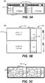
- FIG. 3A is a front view block diagram of a power supply unit 300 including a plurality of AC/DC converters 310 including input connectors 312 according to an example.
- the illustrated example implementation is shown with IEC C19 AC inlet connectors as the input connectors 312, included within a grid structure 311 to release heat and/or admit air through the converters 310 (e.g., into the illustrated front of FIG. 3A , and out the rear toward the module 330 as shown in FIG. 3B ), based on cooling provided by the module 330.
- the grid structure 311 can discharge output air provided by the module 330, in example implementations where the air flow is from rear to front of the converters 310. Accordingly, frontal area of the converters 310 can be devoted to accommodating the input connectors 312, without needing to accommodate a fan(s).
- FIG. 3B is a top view block diagram of the power supply unit 300 including the plurality of AC/DC converters 310 and a module 330 according to an example.
- the fans 338 of the modular PSU 300 are located in the module 330, such that a given AC/DC converter 310 is fanless.
- the module 330 includes two fans 338, to provide cooling for the AC/DC converters 310. In alternate example implementations, one, or more than two, fans can be used, as well as other types of cooling solutions.
- the module 330 is coupled to each AC/DC converter 310 via front couplings 339.
- the illustrated PSU 300 demonstrates an example implementation of a 1+1 parallel design having 2 x fanless AC/DC converters 310 providing first output voltage of 48 V, and 1 x non-isolated DC/DC module 330 with 48 V input, 12 V output, and including 2 x 4028 type fans.
- other voltage values e.g., 24 V
- types of components can be used.
- FIG. 3C is a front view block diagram of a module 330 including a fan 339 and front coupling 339 according to an example.
- the module 330 includes the front coupling 339 at its front, to interface with the plurality of AC/DC converters 310.
- the front coupling 339 can pass power, cooling, signals, and the like between the module 330 and the AC/DC converters 310.
- cooling can be provided to the power supply unit 300 by the module 330, to cool the AC/DC converters 310, and the module 330.
- the module 330 does not need to provide power conversion (e.g., does not need to convert the first output voltage from the AC/DC converters 310 into a second output voltage), and can serve as a fan module to provide cooling while passing the first output voltage from the AC/DC converters 310 through the front coupling 339 to a rear of the module 330.
- the front couplings 339 can serve as 2 x input connectors, e.g., 48V-type input couplings including logic signal pins, to support one or multiple AC/DC converters 310 of the PSU 300.
- the fans 338 are illustrated as 2x 4028 type fans, and other types of fans can be used.
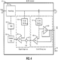
- FIG. 4 is a circuit diagram of a DC/DC converter 420 including a feedback loop 423 according to an example.
- the DC/DC converter 420 can serve as the DC/DC converter of a given AC/DC converter, such as the DC/DC converter 220 illustrated in FIG. 2 .
- the DC/DC converter 420 can be based on an isolated topology to provide first output voltage Vout 403 of 48 V, although other implementations can use other output voltages (e.g., 12 V) and isolated or non-isolated topologies.
- An example control technique is illustrated for the DC/DC converter 420.
- An input voltage, shown as Vbulk 416 (e.g., as received from a power factor correction 214 as illustrated in FIG. 2 ) is received by the power stage 421, which outputs the output voltage Vout 403.
- the output voltage 403 can be monitored by voltage sensing 424 and/or current sensing 427.
- the voltage sensing 424 can be compared, via first operational amplifier 425, to a reference voltage 426.
- the current sensing 427 can be used for current monitoring via Imon 418, and can be used by second Op Amp 428 as input for the reference voltage 426.
- Such results can be fed to the feedback loop 423, then to pulse width modulation 422, then to power stage 421.
- the feedback provided by the example output voltage loop and/or current sharing loop is an example implementation, and other techniques can be used (e.g., without needing to include active current sharing, such as by using a passive-based or droop-based methodology approach).
- FIG. 5 is a circuit diagram of a module 530 including at least one voltage regulator 532 according to an example.
- the module 530 can serve as, e.g., the example module 230 of FIG. 2 . As illustrated, more than one voltage regulator 532 is shown. However, in alternate example implementations, a module 530 can be based on a single voltage regulator 532.
- the at least one voltage regulator 432 is to convert the first DC output voltage 503 (received at the module 530 as input) to the second DC output voltage Vout2 504.
- the module 530 can be based on a non-isolated topology to provide DC-to-DC conversion, with Vout1 being 48 V, and Vout2 being 12 V. In alternate implementations, other voltages and isolated or non-isolated topologies can be used.
- the number of voltage regulators 532 can be chosen based on desired redundancy performance, depending on needs for uptime, reliability, while balancing heat and power dissipation factors.
- the illustrated example current balancing is based on a resistance droop (Rdroop) feedback technique, scaling back the output voltage Vout2 504 as a reference, used as a voltage point for comparison against a reference point to check for a difference to be amplified and corrected for by control circuitry.
- the Ibus signal can serve a similar purpose as the current monitoring Imon 218 described above regarding FIG. 2 , coupled to the voltage regulators for current balancing.
- Ibus, and/or lout can be omitted in alternate example implementations, such that module 530 is operable without needing to include current balancing and/or feedback monitoring.
- FIG. 6 is a block diagram of a system 600 including a plurality of redundantly coupled power supply units 600a, 600b.
- a given one of the power supply units 600a, 600b includes a plurality of AC/DC converters 610, and at least one module 630 according to an example.
- the AC/DC converters 610 are based on isolated DC/DC converters 620, to convert Vbulk 616 to Vout1 603 (Vbulk 616 obtained by the power factor correction 614 converting Vin 602).
- the module 630 is a non-isolated DC/DC converter, to convert Vout1 603 of 48 V to Vout2 604 of 12 V.
- the system 600 illustrates an example 2+2 redundancy architecture deployment (e.g., which can be realized as a 4+0 or 3+1 redundancy).
- the system 600 uses a droop current sharing technique on a 12 V bus, although such buses (e.g., Imon or Ibus) are not specifically needed and can be omitted.
- the current monitoring Imon 618 is shown as being internally tied (e.g., within a given PSU 600a, 600b).
- Imon and/or other control signals
- the upper PSU 600a provides at least two AC input voltage 602 inputs, with the lower PSU 600b providing additional redundancy and/or power outputs.
- the system 600 is shown having two PSUs 600a, 600b, the system 600 can be expanded by adding additional PSUs, and/or by including additional AC/DC converters 610 (and/or modules 630) in a given PSU, to provide additional power and/or redundancy.
- the modular nature of the system 600 enables additional configurations and applications, such as using multiple modules 630 in parallel as shown, which in turn can be fed by multiple AC/DC converters 610. Accordingly, any of, or multiple of, the, isolated DC/DC converters 620 and/or power factor correction units 614 (for example) could fail, and redundancy would enable the system 600 to continue uninterrupted operations.
- the illustrated redundancy configuration can support, e.g., three types of redundancy configuration, such as 4+0, 3+1, or 2+2. Accordingly, upon failure of one of the AC/DC converters 610, the system can then continue operating as other configurations, such as 3+0 or 2+1. In alternate example embodiments, additional redundancy configurations and fallback configuration operations can be used.
Landscapes
- Engineering & Computer Science (AREA)
- Power Engineering (AREA)
- Microelectronics & Electronic Packaging (AREA)
- Physics & Mathematics (AREA)
- Thermal Sciences (AREA)
- Aviation & Aerospace Engineering (AREA)
- Computer Hardware Design (AREA)
- General Engineering & Computer Science (AREA)
- Dc-Dc Converters (AREA)
- Direct Current Feeding And Distribution (AREA)
Applications Claiming Priority (1)
| Application Number | Priority Date | Filing Date | Title |
|---|---|---|---|
| US15/447,553 US10069407B1 (en) | 2017-03-02 | 2017-03-02 | Converters to convert input voltages to output voltages |
Publications (2)
| Publication Number | Publication Date |
|---|---|
| EP3370331A1 true EP3370331A1 (de) | 2018-09-05 |
| EP3370331B1 EP3370331B1 (de) | 2020-12-09 |
Family
ID=61198724
Family Applications (1)
| Application Number | Title | Priority Date | Filing Date |
|---|---|---|---|
| EP18156335.4A Active EP3370331B1 (de) | 2017-03-02 | 2018-02-12 | Stromrichter zur umwandlung von eingangsspannungen in ausgangsspannungen |
Country Status (3)
| Country | Link |
|---|---|
| US (1) | US10069407B1 (de) |
| EP (1) | EP3370331B1 (de) |
| CN (1) | CN108539997B (de) |
Families Citing this family (3)
| Publication number | Priority date | Publication date | Assignee | Title |
|---|---|---|---|---|
| US11376977B2 (en) * | 2018-12-30 | 2022-07-05 | Texas Instruments Incorporated | Powertrain architecture for a vehicle utilizing an on-board charger |
| US11616450B2 (en) * | 2019-03-29 | 2023-03-28 | Qatar Foundation For Education, Science And Community Development | Modular DC-DC converter and a battery charging device including the same |
| JP7414035B2 (ja) * | 2021-03-31 | 2024-01-16 | 横河電機株式会社 | 電源システム及び電源装置 |
Citations (6)
| Publication number | Priority date | Publication date | Assignee | Title |
|---|---|---|---|---|
| US6075698A (en) * | 1998-10-27 | 2000-06-13 | Ads, The Power Resource, Inc. | Removable fan for rack mounted rectifiers |
| US20020181249A1 (en) * | 2000-08-10 | 2002-12-05 | Adc Telecommunications, Inc. | Method and apparatus for distribution of power in a media converter system |
| US20040264131A1 (en) * | 2003-06-24 | 2004-12-30 | Hitachi, Ltd. | Cooling structure for electronic devices |
| US20060056142A1 (en) * | 2004-09-10 | 2006-03-16 | Fumikazu Takahashi | Data processing unit and DC backup power supply |
| US20080040623A1 (en) * | 2003-11-26 | 2008-02-14 | Hitachi, Ltd. | Storage control device and control method therefor |
| JP2009188159A (ja) * | 2008-02-06 | 2009-08-20 | Panasonic Corp | 電力変換装置 |
Family Cites Families (40)
| Publication number | Priority date | Publication date | Assignee | Title |
|---|---|---|---|---|
| US5319536A (en) | 1991-12-17 | 1994-06-07 | International Business Machines Corporation | Power system for parallel operation of AC/DC convertrs |
| US5576941A (en) * | 1994-08-10 | 1996-11-19 | York Technologies, Inc. | Modular power supply system |
| JP2000197347A (ja) | 1998-12-25 | 2000-07-14 | Hitachi Ltd | 電源装置 |
| JP3563038B2 (ja) * | 2001-03-05 | 2004-09-08 | 東芝トランスポートエンジニアリング株式会社 | 電力変換装置 |
| CA2415235C (en) * | 2001-05-21 | 2007-04-10 | Marconi Communications, Inc. | A power system for producing a regulated dc output voltage |
| US8581147B2 (en) * | 2005-03-24 | 2013-11-12 | Lincoln Global, Inc. | Three stage power source for electric ARC welding |
| DE102005024165B3 (de) * | 2005-05-23 | 2006-11-09 | Jet Computer Products Gmbh | Computernetzteil |
| JP4542483B2 (ja) * | 2005-08-31 | 2010-09-15 | 日立コンピュータ機器株式会社 | スイッチング電源装置及びディスクアレイシステム |
| CN2896682Y (zh) * | 2005-11-16 | 2007-05-02 | 安迪生国际股份有限公司 | 电源供应器的改良构造 |
| US7205740B1 (en) * | 2006-03-17 | 2007-04-17 | Delta Elctronics, Inc. | Fan control device for frequency converter |
| JP2009536014A (ja) * | 2006-05-01 | 2009-10-01 | ローズマウント・エアロスペース・インコーポレーテッド | 力率補正を有する汎用acまたはdc航空機装置電源 |
| KR101482101B1 (ko) * | 2006-11-29 | 2015-01-14 | 엘지전자 주식회사 | 공기조화기 |
| US20080291879A1 (en) * | 2007-05-22 | 2008-11-27 | Duff Adam C | Man-Portable Incident Command Platform |
| US8179705B2 (en) * | 2008-05-27 | 2012-05-15 | Power-One, Inc. | Apparatus and method of optimizing power system efficiency using a power loss model |
| US8089219B2 (en) * | 2008-06-27 | 2012-01-03 | Samsung Electro-Mechanics Co., Ltd. | Switching mode power supply for plasma display panel |
| JP2010213787A (ja) * | 2009-03-13 | 2010-09-30 | Shimadzu Corp | 超音波診断装置 |
| CN101895191A (zh) * | 2010-04-08 | 2010-11-24 | 山东高效能服务器和存储研究院 | 用模块电源设计大功率高可靠性服务器电源的方法 |
| US8395917B2 (en) | 2010-06-17 | 2013-03-12 | Hewlett-Packard Development Company, L.P. | Redundant parallel non-isolated input converters |
| US9537434B2 (en) * | 2011-04-01 | 2017-01-03 | Delta Electronics, Inc. | DC electric fan and driving system thereof |
| TWI537474B (zh) * | 2011-04-01 | 2016-06-11 | 台達電子工業股份有限公司 | 直流風扇與直流風扇驅動系統 |
| JP5387651B2 (ja) | 2011-10-21 | 2014-01-15 | 株式会社デンソー | 電源システム |
| WO2013101009A1 (en) * | 2011-12-28 | 2013-07-04 | Intel Corporation | Redundant server system with an optimized failover arrangement |
| US8648498B1 (en) * | 2012-11-19 | 2014-02-11 | Renewable Power Conversion, Inc | Photovoltaic power system with distributed photovoltaic string to polyphase AC power converters |
| US20140153294A1 (en) * | 2012-12-05 | 2014-06-05 | Infineon Technologies Austria Ag | AC/DC Power Converter Arrangement |
| GB2510899A (en) * | 2013-02-19 | 2014-08-20 | Eltek As | Power supply system module |
| JP6048572B2 (ja) * | 2013-03-15 | 2016-12-21 | 富士電機株式会社 | 無停電電源装置 |
| JPWO2014147961A1 (ja) * | 2013-03-19 | 2017-02-16 | 富士電機株式会社 | 電子機器冷却装置およびこれを備える電力変換装置 |
| WO2014158162A1 (en) * | 2013-03-28 | 2014-10-02 | Hewlett-Packard Development Company, L.P. | Converters to provide light load output |
| CN104184200A (zh) * | 2013-05-24 | 2014-12-03 | 台达电子工业股份有限公司 | 电源适配器、电源适配器的控制方法及笔记本 |
| JP6067542B2 (ja) * | 2013-11-11 | 2017-01-25 | 東芝三菱電機産業システム株式会社 | 電力変換装置 |
| US9479047B2 (en) * | 2013-11-27 | 2016-10-25 | Infineon Technologies Austria Ag | System and method for controlling a power supply with a feed forward controller |
| CN105981281B (zh) * | 2013-12-03 | 2018-12-07 | 三菱电机株式会社 | 功率转换装置 |
| US9552031B2 (en) * | 2013-12-20 | 2017-01-24 | Facebook, Inc. | Power shelf for computer servers |
| US9276474B2 (en) * | 2014-02-27 | 2016-03-01 | Edison DC Systems, Inc. | Power conversion system with controlled neutral |
| US10048730B2 (en) * | 2014-05-19 | 2018-08-14 | Dell Products L.P. | Systems and methods for rectifying a voltage using an embedded direct-current-to-direct-current converter |
| JP6269327B2 (ja) * | 2014-06-04 | 2018-01-31 | 株式会社リコー | 制御装置及び画像形成装置 |
| CN104578714B (zh) * | 2015-01-10 | 2017-06-20 | 广东明路电力电子有限公司 | 拼组变流模块结构 |
| US9622373B1 (en) * | 2015-11-13 | 2017-04-11 | Facebook, Inc. | High voltage direct current power system for data centers |
| KR102590108B1 (ko) * | 2015-11-30 | 2023-10-18 | 삼성전자주식회사 | 전력 공급 장치 및 이를 구비한 전기 장치와 진공 청소기 |
| US10340808B2 (en) * | 2015-12-14 | 2019-07-02 | Acbel Polytech Inc. | Redundant power supply apparatus |
-
2017
- 2017-03-02 US US15/447,553 patent/US10069407B1/en active Active
-
2018
- 2018-02-12 EP EP18156335.4A patent/EP3370331B1/de active Active
- 2018-03-01 CN CN201810171073.5A patent/CN108539997B/zh active Active
Patent Citations (6)
| Publication number | Priority date | Publication date | Assignee | Title |
|---|---|---|---|---|
| US6075698A (en) * | 1998-10-27 | 2000-06-13 | Ads, The Power Resource, Inc. | Removable fan for rack mounted rectifiers |
| US20020181249A1 (en) * | 2000-08-10 | 2002-12-05 | Adc Telecommunications, Inc. | Method and apparatus for distribution of power in a media converter system |
| US20040264131A1 (en) * | 2003-06-24 | 2004-12-30 | Hitachi, Ltd. | Cooling structure for electronic devices |
| US20080040623A1 (en) * | 2003-11-26 | 2008-02-14 | Hitachi, Ltd. | Storage control device and control method therefor |
| US20060056142A1 (en) * | 2004-09-10 | 2006-03-16 | Fumikazu Takahashi | Data processing unit and DC backup power supply |
| JP2009188159A (ja) * | 2008-02-06 | 2009-08-20 | Panasonic Corp | 電力変換装置 |
Also Published As
| Publication number | Publication date |
|---|---|
| CN108539997B (zh) | 2020-12-29 |
| EP3370331B1 (de) | 2020-12-09 |
| CN108539997A (zh) | 2018-09-14 |
| US10069407B1 (en) | 2018-09-04 |
| US20180254697A1 (en) | 2018-09-06 |
Similar Documents
| Publication | Publication Date | Title |
|---|---|---|
| CN103633565B (zh) | 配电柜 | |
| US10521001B2 (en) | System and method for rack mountable modular DC power unit | |
| US8103907B2 (en) | Power architecture to provide power supply redundancy | |
| US8937497B1 (en) | Power supply monitor | |
| US6737763B2 (en) | Intelligent load sharing with power limiting scheme for multiple power supplies connected to a common load | |
| CN102474129B (zh) | 备用电源与服务器系统中的主板的直接连结 | |
| EP2333930A2 (de) | Server und darin untergebrachte unterbrechungsfreie Stromversorgung | |
| US10847994B2 (en) | Data center power distribution system | |
| EP2630717B1 (de) | Hochdichte unterbrechungsfreie stromversorgungen sowie zugehörige systeme und stromverteilungseinheiten | |
| CN108781521A (zh) | 用于模块化配电的方法和设备 | |
| US9176555B2 (en) | Power over ethernet power harvester | |
| EP3370331B1 (de) | Stromrichter zur umwandlung von eingangsspannungen in ausgangsspannungen | |
| CN106774771A (zh) | 供电系统及其供电控制方法 | |
| CN108702023A (zh) | 机架电力系统和方法 | |
| US10168721B2 (en) | Controlling redundant power supplies in an information handling system | |
| US10069309B2 (en) | Controlling redundant power supplies in an information handling system | |
| US9647492B2 (en) | Direct current uninterruptible power supply system and device | |
| CN207623922U (zh) | 一种服务器供电系统 | |
| CN114977368B (zh) | 从电力供应装置向负载提供电力的方法和电力分配电路 | |
| CN106249838B (zh) | 用于服务器供电的方法、背板和服务器 | |
| CN112134448A (zh) | 服务器及数据中心 | |
| CN202276167U (zh) | 阵列式电池电源管理装置及其电池电源整合单元 | |
| US20140125128A1 (en) | Power redundancy apparatus for rack-mounted server | |
| CN102073365A (zh) | 一种基于MicroTCA标准的媒体服务器 | |
| US8375230B2 (en) | Managing heat dissipation while testing a power device |
Legal Events
| Date | Code | Title | Description |
|---|---|---|---|
| PUAI | Public reference made under article 153(3) epc to a published international application that has entered the european phase |
Free format text: ORIGINAL CODE: 0009012 |
|
| STAA | Information on the status of an ep patent application or granted ep patent |
Free format text: STATUS: THE APPLICATION HAS BEEN PUBLISHED |
|
| AK | Designated contracting states |
Kind code of ref document: A1 Designated state(s): AL AT BE BG CH CY CZ DE DK EE ES FI FR GB GR HR HU IE IS IT LI LT LU LV MC MK MT NL NO PL PT RO RS SE SI SK SM TR |
|
| AX | Request for extension of the european patent |
Extension state: BA ME |
|
| STAA | Information on the status of an ep patent application or granted ep patent |
Free format text: STATUS: REQUEST FOR EXAMINATION WAS MADE |
|
| 17P | Request for examination filed |
Effective date: 20190214 |
|
| RBV | Designated contracting states (corrected) |
Designated state(s): AL AT BE BG CH CY CZ DE DK EE ES FI FR GB GR HR HU IE IS IT LI LT LU LV MC MK MT NL NO PL PT RO RS SE SI SK SM TR |
|
| STAA | Information on the status of an ep patent application or granted ep patent |
Free format text: STATUS: EXAMINATION IS IN PROGRESS |
|
| 17Q | First examination report despatched |
Effective date: 20190513 |
|
| GRAP | Despatch of communication of intention to grant a patent |
Free format text: ORIGINAL CODE: EPIDOSNIGR1 |
|
| STAA | Information on the status of an ep patent application or granted ep patent |
Free format text: STATUS: GRANT OF PATENT IS INTENDED |
|
| INTG | Intention to grant announced |
Effective date: 20200825 |
|
| GRAS | Grant fee paid |
Free format text: ORIGINAL CODE: EPIDOSNIGR3 |
|
| GRAA | (expected) grant |
Free format text: ORIGINAL CODE: 0009210 |
|
| STAA | Information on the status of an ep patent application or granted ep patent |
Free format text: STATUS: THE PATENT HAS BEEN GRANTED |
|
| AK | Designated contracting states |
Kind code of ref document: B1 Designated state(s): AL AT BE BG CH CY CZ DE DK EE ES FI FR GB GR HR HU IE IS IT LI LT LU LV MC MK MT NL NO PL PT RO RS SE SI SK SM TR |
|
| REG | Reference to a national code |
Ref country code: GB Ref legal event code: FG4D |
|
| REG | Reference to a national code |
Ref country code: AT Ref legal event code: REF Ref document number: 1344406 Country of ref document: AT Kind code of ref document: T Effective date: 20201215 Ref country code: CH Ref legal event code: EP |
|
| REG | Reference to a national code |
Ref country code: DE Ref legal event code: R096 Ref document number: 602018010497 Country of ref document: DE |
|
| REG | Reference to a national code |
Ref country code: IE Ref legal event code: FG4D |
|
| PG25 | Lapsed in a contracting state [announced via postgrant information from national office to epo] |
Ref country code: FI Free format text: LAPSE BECAUSE OF FAILURE TO SUBMIT A TRANSLATION OF THE DESCRIPTION OR TO PAY THE FEE WITHIN THE PRESCRIBED TIME-LIMIT Effective date: 20201209 Ref country code: RS Free format text: LAPSE BECAUSE OF FAILURE TO SUBMIT A TRANSLATION OF THE DESCRIPTION OR TO PAY THE FEE WITHIN THE PRESCRIBED TIME-LIMIT Effective date: 20201209 Ref country code: GR Free format text: LAPSE BECAUSE OF FAILURE TO SUBMIT A TRANSLATION OF THE DESCRIPTION OR TO PAY THE FEE WITHIN THE PRESCRIBED TIME-LIMIT Effective date: 20210310 Ref country code: NO Free format text: LAPSE BECAUSE OF FAILURE TO SUBMIT A TRANSLATION OF THE DESCRIPTION OR TO PAY THE FEE WITHIN THE PRESCRIBED TIME-LIMIT Effective date: 20210309 |
|
| REG | Reference to a national code |
Ref country code: AT Ref legal event code: MK05 Ref document number: 1344406 Country of ref document: AT Kind code of ref document: T Effective date: 20201209 |
|
| PG25 | Lapsed in a contracting state [announced via postgrant information from national office to epo] |
Ref country code: BG Free format text: LAPSE BECAUSE OF FAILURE TO SUBMIT A TRANSLATION OF THE DESCRIPTION OR TO PAY THE FEE WITHIN THE PRESCRIBED TIME-LIMIT Effective date: 20210309 Ref country code: LV Free format text: LAPSE BECAUSE OF FAILURE TO SUBMIT A TRANSLATION OF THE DESCRIPTION OR TO PAY THE FEE WITHIN THE PRESCRIBED TIME-LIMIT Effective date: 20201209 Ref country code: SE Free format text: LAPSE BECAUSE OF FAILURE TO SUBMIT A TRANSLATION OF THE DESCRIPTION OR TO PAY THE FEE WITHIN THE PRESCRIBED TIME-LIMIT Effective date: 20201209 |
|
| REG | Reference to a national code |
Ref country code: NL Ref legal event code: MP Effective date: 20201209 |
|
| PG25 | Lapsed in a contracting state [announced via postgrant information from national office to epo] |
Ref country code: NL Free format text: LAPSE BECAUSE OF FAILURE TO SUBMIT A TRANSLATION OF THE DESCRIPTION OR TO PAY THE FEE WITHIN THE PRESCRIBED TIME-LIMIT Effective date: 20201209 Ref country code: HR Free format text: LAPSE BECAUSE OF FAILURE TO SUBMIT A TRANSLATION OF THE DESCRIPTION OR TO PAY THE FEE WITHIN THE PRESCRIBED TIME-LIMIT Effective date: 20201209 |
|
| REG | Reference to a national code |
Ref country code: LT Ref legal event code: MG9D |
|
| PG25 | Lapsed in a contracting state [announced via postgrant information from national office to epo] |
Ref country code: RO Free format text: LAPSE BECAUSE OF FAILURE TO SUBMIT A TRANSLATION OF THE DESCRIPTION OR TO PAY THE FEE WITHIN THE PRESCRIBED TIME-LIMIT Effective date: 20201209 Ref country code: SK Free format text: LAPSE BECAUSE OF FAILURE TO SUBMIT A TRANSLATION OF THE DESCRIPTION OR TO PAY THE FEE WITHIN THE PRESCRIBED TIME-LIMIT Effective date: 20201209 Ref country code: PT Free format text: LAPSE BECAUSE OF FAILURE TO SUBMIT A TRANSLATION OF THE DESCRIPTION OR TO PAY THE FEE WITHIN THE PRESCRIBED TIME-LIMIT Effective date: 20210409 Ref country code: SM Free format text: LAPSE BECAUSE OF FAILURE TO SUBMIT A TRANSLATION OF THE DESCRIPTION OR TO PAY THE FEE WITHIN THE PRESCRIBED TIME-LIMIT Effective date: 20201209 Ref country code: LT Free format text: LAPSE BECAUSE OF FAILURE TO SUBMIT A TRANSLATION OF THE DESCRIPTION OR TO PAY THE FEE WITHIN THE PRESCRIBED TIME-LIMIT Effective date: 20201209 Ref country code: CZ Free format text: LAPSE BECAUSE OF FAILURE TO SUBMIT A TRANSLATION OF THE DESCRIPTION OR TO PAY THE FEE WITHIN THE PRESCRIBED TIME-LIMIT Effective date: 20201209 Ref country code: EE Free format text: LAPSE BECAUSE OF FAILURE TO SUBMIT A TRANSLATION OF THE DESCRIPTION OR TO PAY THE FEE WITHIN THE PRESCRIBED TIME-LIMIT Effective date: 20201209 |
|
| PG25 | Lapsed in a contracting state [announced via postgrant information from national office to epo] |
Ref country code: AT Free format text: LAPSE BECAUSE OF FAILURE TO SUBMIT A TRANSLATION OF THE DESCRIPTION OR TO PAY THE FEE WITHIN THE PRESCRIBED TIME-LIMIT Effective date: 20201209 Ref country code: PL Free format text: LAPSE BECAUSE OF FAILURE TO SUBMIT A TRANSLATION OF THE DESCRIPTION OR TO PAY THE FEE WITHIN THE PRESCRIBED TIME-LIMIT Effective date: 20201209 |
|
| REG | Reference to a national code |
Ref country code: DE Ref legal event code: R097 Ref document number: 602018010497 Country of ref document: DE |
|
| PG25 | Lapsed in a contracting state [announced via postgrant information from national office to epo] |
Ref country code: IS Free format text: LAPSE BECAUSE OF FAILURE TO SUBMIT A TRANSLATION OF THE DESCRIPTION OR TO PAY THE FEE WITHIN THE PRESCRIBED TIME-LIMIT Effective date: 20210409 Ref country code: MC Free format text: LAPSE BECAUSE OF FAILURE TO SUBMIT A TRANSLATION OF THE DESCRIPTION OR TO PAY THE FEE WITHIN THE PRESCRIBED TIME-LIMIT Effective date: 20201209 |
|
| PLBE | No opposition filed within time limit |
Free format text: ORIGINAL CODE: 0009261 |
|
| STAA | Information on the status of an ep patent application or granted ep patent |
Free format text: STATUS: NO OPPOSITION FILED WITHIN TIME LIMIT |
|
| REG | Reference to a national code |
Ref country code: BE Ref legal event code: MM Effective date: 20210228 |
|
| PG25 | Lapsed in a contracting state [announced via postgrant information from national office to epo] |
Ref country code: AL Free format text: LAPSE BECAUSE OF FAILURE TO SUBMIT A TRANSLATION OF THE DESCRIPTION OR TO PAY THE FEE WITHIN THE PRESCRIBED TIME-LIMIT Effective date: 20201209 Ref country code: CH Free format text: LAPSE BECAUSE OF NON-PAYMENT OF DUE FEES Effective date: 20210228 Ref country code: LI Free format text: LAPSE BECAUSE OF NON-PAYMENT OF DUE FEES Effective date: 20210228 Ref country code: IT Free format text: LAPSE BECAUSE OF FAILURE TO SUBMIT A TRANSLATION OF THE DESCRIPTION OR TO PAY THE FEE WITHIN THE PRESCRIBED TIME-LIMIT Effective date: 20201209 Ref country code: LU Free format text: LAPSE BECAUSE OF NON-PAYMENT OF DUE FEES Effective date: 20210212 |
|
| 26N | No opposition filed |
Effective date: 20210910 |
|
| PG25 | Lapsed in a contracting state [announced via postgrant information from national office to epo] |
Ref country code: DK Free format text: LAPSE BECAUSE OF FAILURE TO SUBMIT A TRANSLATION OF THE DESCRIPTION OR TO PAY THE FEE WITHIN THE PRESCRIBED TIME-LIMIT Effective date: 20201209 Ref country code: SI Free format text: LAPSE BECAUSE OF FAILURE TO SUBMIT A TRANSLATION OF THE DESCRIPTION OR TO PAY THE FEE WITHIN THE PRESCRIBED TIME-LIMIT Effective date: 20201209 |
|
| PG25 | Lapsed in a contracting state [announced via postgrant information from national office to epo] |
Ref country code: FR Free format text: LAPSE BECAUSE OF NON-PAYMENT OF DUE FEES Effective date: 20210228 Ref country code: IE Free format text: LAPSE BECAUSE OF NON-PAYMENT OF DUE FEES Effective date: 20210212 Ref country code: ES Free format text: LAPSE BECAUSE OF FAILURE TO SUBMIT A TRANSLATION OF THE DESCRIPTION OR TO PAY THE FEE WITHIN THE PRESCRIBED TIME-LIMIT Effective date: 20201209 |
|
| PG25 | Lapsed in a contracting state [announced via postgrant information from national office to epo] |
Ref country code: IS Free format text: LAPSE BECAUSE OF FAILURE TO SUBMIT A TRANSLATION OF THE DESCRIPTION OR TO PAY THE FEE WITHIN THE PRESCRIBED TIME-LIMIT Effective date: 20210409 |
|
| PG25 | Lapsed in a contracting state [announced via postgrant information from national office to epo] |
Ref country code: BE Free format text: LAPSE BECAUSE OF NON-PAYMENT OF DUE FEES Effective date: 20210228 |
|
| REG | Reference to a national code |
Ref country code: DE Ref legal event code: R081 Ref document number: 602018010497 Country of ref document: DE Owner name: HEWLETT PACKARD ENTERPRISE DEVELOPMENT LP, SPR, US Free format text: FORMER OWNER: HEWLETT PACKARD ENTERPRISE DEVELOPMENT LP, HOUSTON, TEX., US Ref country code: DE Ref legal event code: R082 Ref document number: 602018010497 Country of ref document: DE Representative=s name: MARKS & CLERK (LUXEMBOURG) LLP, LU |
|
| PG25 | Lapsed in a contracting state [announced via postgrant information from national office to epo] |
Ref country code: CY Free format text: LAPSE BECAUSE OF FAILURE TO SUBMIT A TRANSLATION OF THE DESCRIPTION OR TO PAY THE FEE WITHIN THE PRESCRIBED TIME-LIMIT Effective date: 20201209 |
|
| PG25 | Lapsed in a contracting state [announced via postgrant information from national office to epo] |
Ref country code: HU Free format text: LAPSE BECAUSE OF FAILURE TO SUBMIT A TRANSLATION OF THE DESCRIPTION OR TO PAY THE FEE WITHIN THE PRESCRIBED TIME-LIMIT; INVALID AB INITIO Effective date: 20180212 |
|
| PG25 | Lapsed in a contracting state [announced via postgrant information from national office to epo] |
Ref country code: MK Free format text: LAPSE BECAUSE OF FAILURE TO SUBMIT A TRANSLATION OF THE DESCRIPTION OR TO PAY THE FEE WITHIN THE PRESCRIBED TIME-LIMIT Effective date: 20201209 |
|
| PG25 | Lapsed in a contracting state [announced via postgrant information from national office to epo] |
Ref country code: MT Free format text: LAPSE BECAUSE OF FAILURE TO SUBMIT A TRANSLATION OF THE DESCRIPTION OR TO PAY THE FEE WITHIN THE PRESCRIBED TIME-LIMIT Effective date: 20201209 |
|
| PG25 | Lapsed in a contracting state [announced via postgrant information from national office to epo] |
Ref country code: TR Free format text: LAPSE BECAUSE OF FAILURE TO SUBMIT A TRANSLATION OF THE DESCRIPTION OR TO PAY THE FEE WITHIN THE PRESCRIBED TIME-LIMIT Effective date: 20201209 |
|
| PGFP | Annual fee paid to national office [announced via postgrant information from national office to epo] |
Ref country code: GB Payment date: 20260223 Year of fee payment: 9 |
|
| PGFP | Annual fee paid to national office [announced via postgrant information from national office to epo] |
Ref country code: DE Payment date: 20260220 Year of fee payment: 9 |