EP3370011A1 - One-piece multifunction body for a hydraulic valve assembly used in a combined plant - Google Patents
One-piece multifunction body for a hydraulic valve assembly used in a combined plant Download PDFInfo
- Publication number
- EP3370011A1 EP3370011A1 EP18159593.5A EP18159593A EP3370011A1 EP 3370011 A1 EP3370011 A1 EP 3370011A1 EP 18159593 A EP18159593 A EP 18159593A EP 3370011 A1 EP3370011 A1 EP 3370011A1
- Authority
- EP
- European Patent Office
- Prior art keywords
- attachments
- face
- piece
- multifunction body
- piece multifunction
- Prior art date
- Legal status (The legal status is an assumption and is not a legal conclusion. Google has not performed a legal analysis and makes no representation as to the accuracy of the status listed.)
- Granted
Links
- XLYOFNOQVPJJNP-UHFFFAOYSA-N water Substances O XLYOFNOQVPJJNP-UHFFFAOYSA-N 0.000 claims abstract description 29
- 238000010438 heat treatment Methods 0.000 claims description 16
- 238000004519 manufacturing process Methods 0.000 claims description 9
- 239000007789 gas Substances 0.000 description 7
- 230000000712 assembly Effects 0.000 description 4
- 238000000429 assembly Methods 0.000 description 4
- 230000009467 reduction Effects 0.000 description 4
- 239000002131 composite material Substances 0.000 description 2
- 230000008878 coupling Effects 0.000 description 2
- 238000010168 coupling process Methods 0.000 description 2
- 238000005859 coupling reaction Methods 0.000 description 2
- 238000010586 diagram Methods 0.000 description 2
- 230000010354 integration Effects 0.000 description 2
- 238000010521 absorption reaction Methods 0.000 description 1
- 230000008901 benefit Effects 0.000 description 1
- 238000002485 combustion reaction Methods 0.000 description 1
- 239000003517 fume Substances 0.000 description 1
- 230000007062 hydrolysis Effects 0.000 description 1
- 238000006460 hydrolysis reaction Methods 0.000 description 1
- 230000005226 mechanical processes and functions Effects 0.000 description 1
- 230000035699 permeability Effects 0.000 description 1
- 229920003023 plastic Polymers 0.000 description 1
- 230000000750 progressive effect Effects 0.000 description 1
- 230000035755 proliferation Effects 0.000 description 1
- 230000001105 regulatory effect Effects 0.000 description 1
- 238000007493 shaping process Methods 0.000 description 1
- 230000001629 suppression Effects 0.000 description 1
- 239000012815 thermoplastic material Substances 0.000 description 1
Images


Classifications
-
- F—MECHANICAL ENGINEERING; LIGHTING; HEATING; WEAPONS; BLASTING
- F24—HEATING; RANGES; VENTILATING
- F24H—FLUID HEATERS, e.g. WATER OR AIR HEATERS, HAVING HEAT-GENERATING MEANS, e.g. HEAT PUMPS, IN GENERAL
- F24H9/00—Details
- F24H9/14—Arrangements for connecting different sections, e.g. in water heaters
- F24H9/142—Connecting hydraulic components
- F24H9/144—Valve seats, piping and heat exchanger connections integrated into a one-piece hydraulic unit
-
- F—MECHANICAL ENGINEERING; LIGHTING; HEATING; WEAPONS; BLASTING
- F24—HEATING; RANGES; VENTILATING
- F24D—DOMESTIC- OR SPACE-HEATING SYSTEMS, e.g. CENTRAL HEATING SYSTEMS; DOMESTIC HOT-WATER SUPPLY SYSTEMS; ELEMENTS OR COMPONENTS THEREFOR
- F24D3/00—Hot-water central heating systems
- F24D3/10—Feed-line arrangements, e.g. providing for heat-accumulator tanks, expansion tanks ; Hydraulic components of a central heating system
- F24D3/105—Feed-line arrangements, e.g. providing for heat-accumulator tanks, expansion tanks ; Hydraulic components of a central heating system pumps combined with multiple way valves
Definitions
- the present invention mainly relates to a one-piece multifunction body for a hydraulic valve assembly.
- the hydraulic valve assembly is used in a boiler, in particular in a condensing boiler, or in a geothermal heat pump.
- the present invention also relates to a hydraulic valve assembly using a one-piece multifunction body made according to the teachings of the present invention.
- a further object of the present invention is to provide a boiler, in particular a condensing boiler, provided with at least one hydraulic valve assembly comprising at least one one-piece multifunction body made according to the teachings of the present invention.
- Heat pumps are combined machines for room heating and domestic hot water production with matching storage tanks of adequate capacity.
- These machines have a hydraulic heat distribution circuit basically corresponding to the one of gas boilers, with separate storage tanks for the production of domestic hot water.
- the layout of heat pumps normally provides a hydraulic circuit consisting mainly of pipes and fittings for connecting the components and functional devices of the machine.
- Compact multifunction housing units designed to house all devices of the heat distribution hydraulic system are still in an embryonic state, since the layout of the heat pumps is still various.
- the standardization of the hydraulic circuit increases production volumes and allows designing and investing in the making of new highly integrated multifunction hydraulic assemblies, carefully sized with low load losses and high flow rates to be used on heat pumps and/or on medium-power condensing boilers.
- the new hydraulic assembly for medium-power boilers and for domestic heat pumps is designed and produced by providing versatile attachments and orientations to ease the introduction on layouts of existing machines, while still allowing the manufacturers to maintain a significant diversification of the hydraulic circuit as well. Therefore, the main object of the present invention is to provide an extremely compact hydraulic valve assembly for boilers, whose components are reduced to a single multifunction valve body integrating all control and safety devices, which is predisposed to the coupling with the rest of the hydraulic circuit by means of quick attachments.
- the present description focuses on a simple combined plant for room heating and for the production of domestic hot water using a domestic hot water storage tank, the teachings of the invention may also be extended to a more complex plant, also providing for the use of a heat pump. However, said heat pump plant will not be described in detail not to burden the present description.
- 10 indicates a combined plant for room heating and domestic hot water production.
- a one-piece multifunction body for a hydraulic valve assembly made according to the teachings of the present invention is integrated in said combined plant 10.
- the combined plant 10 comprises a condensing boiler 11 and a hydraulic network 12, hydraulically connected to each other.
- the hydraulic network 12 comprises, in a known manner, a primary heating circuit (C1) and a secondary circuit (C2) for domestic hot water.
- the primary circuit (C1) comprises a heating hot water delivery duct 50 to at least one heating plant (IR) and a cold water return duct 51 to the condensing boiler 11.
- the secondary circuit (C2) comprises at least one storage tank (SER) of domestic hot water.
- SER storage tank
- the storage tank (SER) is supplied with cold water through an inlet duct (CI) for cold water coming from the aqueduct (not shown).
- the storage tank (SER) has an outlet duct (CU) for domestic hot water that can thus flow towards a point of use (not shown) comprising, for example, one or more taps (not shown).
- a delivery duct 52 exiting a boiler body (CC) at some point splits into two separate ducts, namely in the aforementioned heating hot water delivery duct 50 and in a delivery duct 53 of a coil 54 immersed in the water contained in the storage tank (SER).
- the hot water of the primary circuit (C1) flowing in the coil 54 heats the sanitary water contained in the storage tank (SER). It comes out of the coil 54 flowing in a return duct 55 to the condensing boiler 11.
- the gas condensing boiler 11 comprises the aforesaid boiler body (CC), which in turn comprises:
- the hydraulic valve assembly 20 comprises, besides a one-piece multifunction body 27 (which will be described in greater detail below), the following devices:
- FIG. 4 also shows the presence of a fixing jumper (CVT) which, as better shown below, serves to fix the scroll 24 to the one-piece multifunction body 27.
- CVT fixing jumper
- the hydraulic valve assembly 20 is used as an apparatus for regulating the water flow from/to the condensing boiler 11 in which the hydraulic valve assembly 20 is inserted.
- Figure 6 shows a first alternative layout of the hydraulic valve assembly shown in Figures 4 and 5 .
- the one-piece multifunction body 27 is rotated 90° anticlockwise (arrow (R1)) so that the three-way valve 30 and the air vent valve 26 can be screwed on the upper face of the one-piece multifunction body 27.
- the by-pass device 38 is screwed onto the rear face of the one-piece multifunction body 27, whereas the two threaded fittings 61, 62 are screwed onto the right face of the one-piece multifunction body 27.
- the pressure switch 29 and the safety valve 33 have instead been mounted on the left side of the one-piece multifunction body 27, whereas the fitting 28A and the plug 63 have been mounted on its lower face.
- the scroll 24 has been rotated 90° clockwise (arrow (R2)) so that the delivery of the centrifugal pump assembly 21 is on the right instead of upwards as in the previous embodiments shown in Figures 4-7 .
- the spatial arrangement of the one-piece multifunction body 27, and consequently also of the hydraulic valve assembly 20 in which this body is inserted depends on the structural and design characteristics of the condensing boiler 11 in which the whole hydraulic valve assembly 20 must be integrated.
- the one-piece multifunction body 27 comprises a main hollow body 27A made of a piece.
- the extreme compactness of the main hollow body 27A even involves the possible use of a single composite material, said composite material being a thermoplastic material, also called “technopolymer”, which guarantees a good resistance to high operating temperatures together with a low permeability to water absorption (hydrolysis).
- the aforesaid main hollow body 27A has a substantially polyhedral hollow shape provided with a plurality of openings formed on the faces of the polyhedron.
- the main hollow body 27A has a hollow shape having six faces ( Figures 9-11 ):
- a front hole 71 provided with a cylindrical collar 71A projecting from the front frontal face (FC1), is formed in the front frontal face (FC1).
- cylindrical collar 71A there are four tangential recesses 71B, 71C, 71D, 71E which, as explained below, can be innovatively coupled to the aforementioned scroll 24 of the centrifugal pump assembly 21 (see below).
- a pair of ambidextrous bars 81, 82 are prismatically engaged with a first pair 71B, 71D or with a second pair 71C, 71E of tangential recesses; as better shown below, the two drilled ambidextrous bars 81, 82 are fixed to the scroll 24 (see below).
- CVT fixing jumper
- Both the first pair 71B, 71D and the second pair 71C, 71E of tangential recesses are respectively formed by two straight and parallel tangential recesses.
- the main hollow body 27A has a central cavity 85 in hydraulic communication with the front hole 71 that, as previously stated, is on the front frontal face (FC1).
- the right side face (FC3) has a lower attachment 87A designed to house the cartridge-shaped three-way valve 30, which can be screwed, in a known manner and by means of screws not shown, to two threaded holes 87A*, 87A**.
- the lower attachment 87A is overhung by an upper attachment 87B to which e.g., the fitting 28A to the expansion vessel 28 can be coupled by pressure ( Figure 4 ).
- the upper attachment 87B ( Figure 10 ) is provided with two holes 87B*, 87B** in which a jumper (substantially shaped as a U-shaped hairpin) is inserted. Once inserted into the two holes 87B*, 87B**, the jumper prevents the fitting 28A from being extracted from the upper attachment 87B ( Figure 10 ).
- the left side face (FC4) ( Figure 9 ) has the same attachments 87A, 87B, which are identical to those already described with respect to the right side face (FC3) and therefore will not be described again.
- Each attachment 87B on the upper face (FC5) is close to an identical attachment 87B on the right side face (FC3), or on the left side face (FC4), respectively.
- the symmetry axis of each attachment 87B on the upper face (FC5) is perpendicular to the symmetry axis of the respective attachment 87B on the left side face (FC3) and on the right side face (FC4), respectively.
- the attachments 87B are grouped into two pairs. Each pair is arranged at an upper vertex of the main hollow body 27A.
- the lower face (FC6) provides a pair of identical threaded attachments 86A on which the aforementioned threaded fittings 61, 62 are screwed ( Figure 12 ) .
- the lower face (FC6) also has a further threaded attachment 88A ( Figure 12 ), which is offset with respect to an ideal straight line connecting the centres of the two threaded attachments 86A.
- the aforementioned drainage tap 35 is screwed onto this threaded attachment 88A.
- the central hole 71 and the attachments 86A, 87A, 87B, 86A are all in hydraulic communication with each other and with the aforementioned central cavity 85.
- multifunction has been associated with the one-piece body 27 since this element performs both hydraulic and mechanical functions, physically supporting a plurality of devices.
- the one-piece multifunction body 27 object of the invention comprises the aforementioned main hollow body 27A having a substantially polyhedral shape, and is provided with:
- Figure 12A shows that a plane ( ⁇ ) perpendicular to the two straight lines (X1), (X2) and passing through the centre (C1) of the central hole 71 divides the one-piece multifunction body 27 into two identical and specularly symmetrical halves 27* and 27**.
- the hydraulic valve assembly 20 can be provided with additional plugs (not shown) to close one or more attachments 86A, 87A, 87B, 86A as needed for shaping to the best the hydraulic valve assembly 20 to be received in the condensing boiler 11 in the best possible working conditions.
- Figure 13 shows the scroll 24 in more detail and according to different views.
- Said scroll 24 comprises a main hollow body 24A having a front frontal face (FC7) provided with a substantially square flange 91 having four threaded through holes 91A at the four corners.
- screws (not shown) can be screwed to attach reversibly the scroll 24 to the electric motor 22 ( Figures 1 , 3 ).
- a left side face (FC8) of the scroll 24 is provided with an attachment 92, which can be coupled e.g. to a pressure gauge 37 or a pressure switch 29, or which can be closed by a suitable plug (not shown).
- the upper face (FC9) is also provided with a further attachment 92 (identical to the attachment 92 on the left side face (FC8)) to insert e.g. the pressure switch 29.
- the pressure switch 29 can be coupled as desired to one of the two attachments 92 based on the orientation of the scroll 24.
- the pressure switch 29 is mounted directly on the one-piece multifunction body 27 (more precisely in one of the two upper attachments 87B) or it can be coupled to one of the two attachments 92.
- the upper attachments 87B and the free attachments 92 are closed with appropriate plugs (not shown).
- the attachments 92 are identical and are arranged on substantially perpendicular faces (FC8), (FC9).
- the flange 91 of the front face (FC7) encloses a snail-shaped cavity 94 in hydraulic communication with a central through hole 95, with the two attachments 92 and with the delivery attachment 93.
- the snail-shaped cavity 94 contains the impeller 23 of the centrifugal pump assembly 21 ( FIG. 1 ). The water is then sucked by the impeller 23 through the central through hole 95 (coupled to the front hole 71 on the front face (FC1) of the one-piece multifunction body 27) and sent to the primary heat exchanger 14 through the delivery attachment 93.
- the two bars 81, 82 can be each time prismatically coupled to a first pair of recesses 71B, 71D or to a second pair of recesses 71C, 71E so that the scroll 24 can be spatially oriented in four different ways, as shown in Figures 14-17 .
- the one-piece multifunction body 27 comprises at least one type of attachments 86A, 87A, 87B, which, in turn, comprises at least two identical attachments 86A, 87A, 87B on different faces of the polyhedron (FC1), (FC2), (FC3), (FC4) to allow an extremely flexible spatial orientation of the main hollow body 27A.
- the main advantage of the one-piece multifunction body object of the present invention consists in providing innumerable configurations of the whole hydraulic valve assembly with rational arrangements of the functional elements, thus making its use possible in many types of heating plants.
Landscapes
- Engineering & Computer Science (AREA)
- Physics & Mathematics (AREA)
- Thermal Sciences (AREA)
- Chemical & Material Sciences (AREA)
- Combustion & Propulsion (AREA)
- Mechanical Engineering (AREA)
- General Engineering & Computer Science (AREA)
- Multiple-Way Valves (AREA)
Abstract
Description
- This application claims priority from Italian Patent Application No.
102017000022780 filed on March 1, 2017 - The present invention mainly relates to a one-piece multifunction body for a hydraulic valve assembly. The hydraulic valve assembly is used in a boiler, in particular in a condensing boiler, or in a geothermal heat pump.
- The present invention also relates to a hydraulic valve assembly using a one-piece multifunction body made according to the teachings of the present invention.
- A further object of the present invention is to provide a boiler, in particular a condensing boiler, provided with at least one hydraulic valve assembly comprising at least one one-piece multifunction body made according to the teachings of the present invention.
- As known, the hydraulic assemblies for combined boilers developed in recent years have undergone a significant rationalization of the hydraulic components with the progressive abandonment of single monofunction components connected to each other by means of pipes in favour of increasingly compact multifunction control and safety devices, said devices having have been designed to perform all the hydraulic functions of the boiler.
- It is also known that since the beginning of the 1990s up to ten years ago, in the domestic heating field, multifunction hydraulic assemblies for combined boilers have undergone a considerable evolution, gradually integrating more and more components, devices and functions of the boiler hydraulic circuit.
- Therefore, the efforts of the engineers have been directed above all to the reduction of the size and of the manufacturing costs.
- All this has actually led to the suppression of connecting pipes in favour of very compact multifunction housing units designed to house all the devices of the hydraulic circuit of a combined boiler.
- Some typical one-piece bodies for hydraulic assemblies are described and shown in the documents
GB-A-3 388 422 EP-A1-1 026 457 andUS-A1-2014/0224194 . - This ever-increasing integration of the hydraulic system has been induced by the large volumes at stake, which today in Europe alone are around five to six millions of combined boilers produced each year.
- It is also well known that the new objectives of the European Union for domestic heating aim at encouraging the use of electricity-powered heat pumps as an alternative to traditional gas- or oil-powered boilers.
- The latest generation of heat pumps has remarkably higher yields than condensing gas boilers and is increasingly employed for new underfloor heating plants in new ecological buildings.
- Heat pumps are combined machines for room heating and domestic hot water production with matching storage tanks of adequate capacity.
- These machines have a hydraulic heat distribution circuit basically corresponding to the one of gas boilers, with separate storage tanks for the production of domestic hot water.
- The layout of heat pumps normally provides a hydraulic circuit consisting mainly of pipes and fittings for connecting the components and functional devices of the machine.
- Compact multifunction housing units designed to house all devices of the heat distribution hydraulic system are still in an embryonic state, since the layout of the heat pumps is still various.
- This causes a proliferation of variants on hydraulic circuits with low amounts of products, or in any case amounts that do not justify any major investment in the integration of components.
- At present, therefore, heating plants using heat pumps are strongly in need of a standardization of the hydraulic layout.
- The standardization of the hydraulic circuit increases production volumes and allows designing and investing in the making of new highly integrated multifunction hydraulic assemblies, carefully sized with low load losses and high flow rates to be used on heat pumps and/or on medium-power condensing boilers.
- Therefore, the new hydraulic assembly for medium-power boilers and for domestic heat pumps according to the present invention is designed and produced by providing versatile attachments and orientations to ease the introduction on layouts of existing machines, while still allowing the manufacturers to maintain a significant diversification of the hydraulic circuit as well. Therefore, the main object of the present invention is to provide an extremely compact hydraulic valve assembly for boilers, whose components are reduced to a single multifunction valve body integrating all control and safety devices, which is predisposed to the coupling with the rest of the hydraulic circuit by means of quick attachments. Although the present description focuses on a simple combined plant for room heating and for the production of domestic hot water using a domestic hot water storage tank, the teachings of the invention may also be extended to a more complex plant, also providing for the use of a heat pump. However, said heat pump plant will not be described in detail not to burden the present description.
- The present invention will now be described with reference to the accompanying drawings showing non-limiting embodiments thereof with the proviso that, given the particular complexity of the drawings and the high number of details, not all the elements have been numbered; in which:
-
Figure 1 shows a schematic diagram of a combined plant for room heating and domestic hot water production; -
Figure 2 shows a diagram of a hydraulic valve assembly contained in the combined plant ofFigure 1 ; -
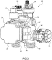
Figure 3 shows a perspective view of the hydraulic valve assembly ofFigure 2 ; -
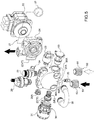
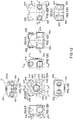
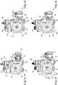
Figure 4 shows an exploded view of the hydraulic valve assembly shown inFigure 3 observed from a first point of view; -
Figure 5 shows the same exploded view of the hydraulic valve assembly shown inFigure 4 observed from a second point of view (opposite the first point of view); -
Figure 6 shows a first alternative layout of the hydraulic valve assembly as shown inFigures 4 and5 ; -
Figure 7 shows a second alternative layout of the hydraulic valve assembly as shown inFigures 4 and5 ; -
Figure 8 shows a third alternative layout of the hydraulic valve assembly as shown inFigures 4 and5 ; -
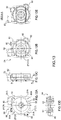
Figure 9 shows a first perspective view of a one-piece multifunction body contained in the hydraulic valve assembly referred to inFigures 2-8 ; -
Figure 10 shows a second perspective view of a one-piece multifunction body contained in the hydraulic valve assembly as shown inFigures 2-8 ; -
Figure 11 shows a front view (with a sectioned portion) of the one-piece multifunction body according toFigures 9, 10 ; -
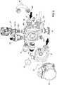
Figure 12 shows various significant views and sections of the one-piece multifunction body according toFigures 9-11 ; -
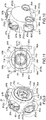
Figure 13 shows various significant views and sections of a scroll belonging to a centrifugal pump assembly contained in the combined plant ofFigure 1 ; and -
Figures 14-17 show four possible couplings between the one-piece multifunction body according toFigures 9-12 and the scroll shown inFigure 13 . - In
Figure 1 ,10 indicates a combined plant for room heating and domestic hot water production. - As explained hereinafter, a one-piece multifunction body for a hydraulic valve assembly made according to the teachings of the present invention is integrated in said combined
plant 10. - The combined
plant 10 comprises acondensing boiler 11 and ahydraulic network 12, hydraulically connected to each other. - The
hydraulic network 12, in turn, comprises, in a known manner, a primary heating circuit (C1) and a secondary circuit (C2) for domestic hot water. - The primary circuit (C1) comprises a heating hot
water delivery duct 50 to at least one heating plant (IR) and a coldwater return duct 51 to thecondensing boiler 11. - On the other hand, the secondary circuit (C2) comprises at least one storage tank (SER) of domestic hot water.
- In particular, the storage tank (SER) is supplied with cold water through an inlet duct (CI) for cold water coming from the aqueduct (not shown). Furthermore, the storage tank (SER) has an outlet duct (CU) for domestic hot water that can thus flow towards a point of use (not shown) comprising, for example, one or more taps (not shown).
- As shown in
Figure 1 , adelivery duct 52 exiting a boiler body (CC) at some point splits into two separate ducts, namely in the aforementioned heating hotwater delivery duct 50 and in adelivery duct 53 of acoil 54 immersed in the water contained in the storage tank (SER). The hot water of the primary circuit (C1) flowing in thecoil 54 heats the sanitary water contained in the storage tank (SER). It comes out of thecoil 54 flowing in areturn duct 55 to the condensingboiler 11. - As shown in
Figure 1 , thegas condensing boiler 11 comprises the aforesaid boiler body (CC), which in turn comprises: - a premix gas burner 13 (which is associated with a gas delivery line (LG) controlled by a safety gas valve (VV));
- a main
condensing heat exchanger 14; - a chimney (CHM) for the evacuation of the fumes produced by the gas combustion in the boiler body (CC);
- a cold
water delivery duct 15 for transferring the cold water to themain heat exchanger 14; - a
hydraulic valve assembly 20 hydraulically connected, on the one side, to the boiler body (CC), and on the other side, to thereturn duct 51 of the heating plant (IR) and to thereturn duct 55 of the water leaving thecoil 54 immersed in the storage tank (SER) of the secondary circuit (C2) . - As shown in more detail in
Figures 2-5 , thehydraulic valve assembly 20 comprises, besides a one-piece multifunction body 27 (which will be described in greater detail below), the following devices: - a
centrifugal pump assembly 21 comprising, in turn, anelectric motor 22, which rotates an impeller 23 (Figure 1 ), in turn enclosed in ascroll 24 provided with amanometer 37; - an
air vent valve 26; - a fitting 28A with an expansion vessel 28 (
Figure 1 ); - a
pressure switch 29; - a three-
way valve 30 advantageously shaped as a screw-on cartridge (comprising, in turn, anelectric motor 31, which, in turn, actuates a relevant shutter (OTT) opposed by a spring (ML)); - a
safety valve 33 which, when required, drains the water through anexhaust duct 34; - a
plant drainage tap 35, also passing through theaforementioned exhaust duct 34; - a by-
pass device 38 provided with a by-pass valve 38A; - two threaded
fittings multifunction body 27 with the return duct 55 (Figure 1 ) of the water leaving thecoil 54 and with the return duct 51 (Figure 1 ) of the heating plant (IR) ; - a three-
way valve cap 63. -
Figure 4 also shows the presence of a fixing jumper (CVT) which, as better shown below, serves to fix thescroll 24 to the one-piecemultifunction body 27. - The
hydraulic valve assembly 20 is used as an apparatus for regulating the water flow from/to the condensingboiler 11 in which thehydraulic valve assembly 20 is inserted.Figure 6 shows a first alternative layout of the hydraulic valve assembly shown inFigures 4 and5 . - In this layout, the three-
way valve 30 and the fitting 28A have been moved to the left face of the one-piecemultifunction body 27, whereas thepressure switch 29 and the three-way valve plug 63 have been mounted on the right side of the one-piecemultifunction body 27. In the same layout ofFigure 6 , theair vent valve 26 and the safety valve have exchanged seats, whereas the by-pass device 38 has been overturned. All other devices have maintained the same position with respect to the one-piecemultifunction body 27. - In the second alternative layout of
Figure 7 , the positions of the layout shown inFigures 4 and5 have been substantially maintained. Only the positions of the by-pass device 38 (now screwed onto the lower face of the one-piece multifunction body 27) and of the two threadedfittings 61, 62 (now screwed onto the rear face of the one-piece multifunction body 27) have changed. - On the other hand, in the third alternative layout of
Figure 8 , the one-piecemultifunction body 27 is rotated 90° anticlockwise (arrow (R1)) so that the three-way valve 30 and theair vent valve 26 can be screwed on the upper face of the one-piecemultifunction body 27. In such a configuration, the by-pass device 38 is screwed onto the rear face of the one-piecemultifunction body 27, whereas the two threadedfittings multifunction body 27. Thepressure switch 29 and thesafety valve 33 have instead been mounted on the left side of the one-piecemultifunction body 27, whereas the fitting 28A and theplug 63 have been mounted on its lower face. In the layout ofFigure 8 , thescroll 24 has been rotated 90° clockwise (arrow (R2)) so that the delivery of thecentrifugal pump assembly 21 is on the right instead of upwards as in the previous embodiments shown inFigures 4-7 . - In short, the spatial arrangement of the one-piece
multifunction body 27, and consequently also of thehydraulic valve assembly 20 in which this body is inserted, depends on the structural and design characteristics of the condensingboiler 11 in which the wholehydraulic valve assembly 20 must be integrated. - As shown in more detail in
Figures 9 to 11 , the one-piecemultifunction body 27 comprises a mainhollow body 27A made of a piece. - The extreme compactness of the main
hollow body 27A even involves the possible use of a single composite material, said composite material being a thermoplastic material, also called "technopolymer", which guarantees a good resistance to high operating temperatures together with a low permeability to water absorption (hydrolysis). - The aforesaid main
hollow body 27A has a substantially polyhedral hollow shape provided with a plurality of openings formed on the faces of the polyhedron. Advantageously, but not necessarily, the mainhollow body 27A has a hollow shape having six faces (Figures 9-11 ): - a front frontal face (FC1);
- a rear frontal face (FC2);
- a right side face (FC3);
- a left side face (FC4);
- an upper face (FC5);
- a lower face (FC6).
- A
front hole 71, provided with acylindrical collar 71A projecting from the front frontal face (FC1), is formed in the front frontal face (FC1). - On the
cylindrical collar 71A there are fourtangential recesses aforementioned scroll 24 of the centrifugal pump assembly 21 (see below). - As better shown in
Figure 13B , a pair ofambidextrous bars 81, 82 (internally drilled to receive a fixing jumper (CVT)) are prismatically engaged with afirst pair second pair ambidextrous bars - Both the
first pair second pair - As shown in
Figures 9 to 11 , the mainhollow body 27A has acentral cavity 85 in hydraulic communication with thefront hole 71 that, as previously stated, is on the front frontal face (FC1). - In the lower part of the rear frontal face (FC2) there are two threaded
attachments 86A to which the by-pass device 38 can be coupled. The two threadedattachments 86A are in hydraulic communication with thecentral cavity 85. - As shown in
Figure 10 , the right side face (FC3) has alower attachment 87A designed to house the cartridge-shaped three-way valve 30, which can be screwed, in a known manner and by means of screws not shown, to two threadedholes 87A*, 87A**. - The
lower attachment 87A is overhung by anupper attachment 87B to which e.g., the fitting 28A to theexpansion vessel 28 can be coupled by pressure (Figure 4 ). Theupper attachment 87B (Figure 10 ) is provided with twoholes 87B*, 87B** in which a jumper (substantially shaped as a U-shaped hairpin) is inserted. Once inserted into the twoholes 87B*, 87B**, the jumper prevents the fitting 28A from being extracted from theupper attachment 87B (Figure 10 ). - The left side face (FC4) (
Figure 9 ) has thesame attachments - Two
attachments 87B are provided on the upper face (FC5) . Eachattachment 87B on the upper face (FC5) is close to anidentical attachment 87B on the right side face (FC3), or on the left side face (FC4), respectively. The symmetry axis of eachattachment 87B on the upper face (FC5) is perpendicular to the symmetry axis of therespective attachment 87B on the left side face (FC3) and on the right side face (FC4), respectively. - In other words, the
attachments 87B are grouped into two pairs. Each pair is arranged at an upper vertex of the mainhollow body 27A. - The lower face (FC6), on the other hand, provides a pair of identical threaded
attachments 86A on which the aforementioned threadedfittings Figure 12 ) . - The lower face (FC6) also has a further threaded
attachment 88A (Figure 12 ), which is offset with respect to an ideal straight line connecting the centres of the two threadedattachments 86A. - The
aforementioned drainage tap 35 is screwed onto this threadedattachment 88A. - The
central hole 71 and theattachments central cavity 85. - Incidentally, the term "multifunction" has been associated with the one-
piece body 27 since this element performs both hydraulic and mechanical functions, physically supporting a plurality of devices. - In particular, the one-piece
multifunction body 27 object of the invention comprises the aforementioned mainhollow body 27A having a substantially polyhedral shape, and is provided with: - a first plurality of
hydraulic attachments 86A arranged on the faces (FC1), (FC2), (FC3), (FC4), (FC5), (FC6) of the polyhedron;
and - a second plurality of
functional attachments functional attachments attachments 87A designed to house a three-way valve 30. - Now consider a first straight line (X1) connecting the centres of the two
attachments 87A, and a second straight line (X2) connecting the centres of the twoattachments 87B (Figure 12A ). -
Figure 12A shows that a plane (ψ) perpendicular to the two straight lines (X1), (X2) and passing through the centre (C1) of thecentral hole 71 divides the one-piecemultifunction body 27 into two identical and specularlysymmetrical halves 27* and 27**. - This specular symmetry is quite relevant to give the product an extremely flexible spatial orientation with regard to its positioning (
Figures 3-8 ). - Obviously, apart from the aforementioned three-
way valve plug 63, thehydraulic valve assembly 20 can be provided with additional plugs (not shown) to close one ormore attachments hydraulic valve assembly 20 to be received in the condensingboiler 11 in the best possible working conditions. -
Figure 13 shows thescroll 24 in more detail and according to different views. - Said
scroll 24 comprises a mainhollow body 24A having a front frontal face (FC7) provided with a substantiallysquare flange 91 having four threaded throughholes 91A at the four corners. - In the threaded through
holes 91A, screws (not shown) can be screwed to attach reversibly thescroll 24 to the electric motor 22 (Figures 1 ,3 ). - A left side face (FC8) of the
scroll 24 is provided with anattachment 92, which can be coupled e.g. to apressure gauge 37 or apressure switch 29, or which can be closed by a suitable plug (not shown). - On an upper face (FC9) of the
scroll 24 there is adelivery attachment 93 connected to the coldwater delivery duct 15 to the main heat exchanger 14 (Figure 1 ). - The upper face (FC9) is also provided with a further attachment 92 (identical to the
attachment 92 on the left side face (FC8)) to insert e.g. thepressure switch 29. - The
pressure switch 29 can be coupled as desired to one of the twoattachments 92 based on the orientation of thescroll 24. - In other words, the
pressure switch 29 is mounted directly on the one-piece multifunction body 27 (more precisely in one of the twoupper attachments 87B) or it can be coupled to one of the twoattachments 92. - Depending on where the
pressure switch 29 is mounted, theupper attachments 87B and thefree attachments 92 are closed with appropriate plugs (not shown). - The
attachments 92 are identical and are arranged on substantially perpendicular faces (FC8), (FC9). - The
flange 91 of the front face (FC7) encloses a snail-shapedcavity 94 in hydraulic communication with a central throughhole 95, with the twoattachments 92 and with thedelivery attachment 93. - In use, the snail-shaped
cavity 94 contains theimpeller 23 of the centrifugal pump assembly 21 (FIG. 1 ). The water is then sucked by theimpeller 23 through the central through hole 95 (coupled to thefront hole 71 on the front face (FC1) of the one-piece multifunction body 27) and sent to theprimary heat exchanger 14 through thedelivery attachment 93. - As shown in
Figure 13 , on a rear frontal face (FC10) (of the scroll 24), besides the aforementioned central throughhole 95 there are twoambidextrous bars ambidextrous bars hole 95. - As previously stated, the two
bars recesses recesses scroll 24 can be spatially oriented in four different ways, as shown inFigures 14-17 . - In short, the one-piece
multifunction body 27 comprises at least one type ofattachments identical attachments hollow body 27A. - In particular:
- a first type of
attachments 86A comprises four identical attachments, two arranged on the rear frontal face (FC2), and, respectively, two arranged on the lower face (FC6); - a second type of
attachments 87A comprises two identical opposite attachments, one arranged on the right side face (FC3), and, respectively, one arranged on the left side face (FC4); - a third type of
attachments 87B comprises four identical attachments, two arranged on the upper face (FC5), and, respectively, one arranged on the right side face (FC3) and one arranged on the left side face (FC4). - Besides the embodiments shown in the accompanying Figures, the person skilled in the art can appreciate that, by varying the spatial position of the one-piece multifunction body and/or the arrangement of the various devices mounted on the one-piece multifunction body and/or the spatial position of the scroll of the centrifugal pump assembly, countless configurations of the whole hydraulic valve assembly can be obtained, thus allowing the hydraulic assembly manufacturer to satisfy the most different requests from the producers of combined plants and/or boilers.
- However, it should be clear that, although the present invention has been described in the context of a traditional system, all the present teachings can be applied, without significant changes, to a system comprising a heat pump.
- The main advantage of the one-piece multifunction body object of the present invention consists in providing innumerable configurations of the whole hydraulic valve assembly with rational arrangements of the functional elements, thus making its use possible in many types of heating plants.
- All this means a significant reduction in investment costs in moulds and equipment, as well as a substantial reduction in the overall size of the product and, therefore, in a consequent reduction in manufacturing costs.
Claims (11)
- A one-piece multifunction body (27) for a hydraulic valve assembly (20) used in a combined plant (10) for room heating and for the instantaneous production of domestic hot water; the one-piece multifunction body (27) comprising a main hollow body (27A) having a substantially polyhedral shape provided with:- a first plurality of hydraulic attachments (86A, 87A, 87B) obtained on the faces ((FC1), (FC2), (FC3), (FC4), (FC5), (FC6)) of the polyhedron; and- a second plurality of functional attachments (87A, 87B), also obtained on the faces ((FC1), (FC2), (FC3), (FC4), (FC5), (FC6)) of the polyhedron; said second plurality of functional attachments (87A, 87B) comprising attachments (87A) designed to house a three-way valve (30);said second plurality of functional attachments (87A, 87B) being designed to be coupled to a plurality of control and interception devices (26, 28A, 29, 30, 33, 35, 38, 61, 62, 63) to control and intercept the water flow inside said main hollow body (27A); said control and interception devices (26, 28A, 29, 30, 33, 35, 38, 61, 62, 63) comprising a three-way valve (30);
said one-piece multifunction body (27) being characterized in that at least one type of attachments (86A, 87A, 87B) of said first plurality (8eA) or of said second plurality (87A, 87B) comprises at least two identical attachments (86A, 87A, 87B) obtained on different faces ((FC1), (FC2), (FC3), (FC4), (FC5), (FC6)) of the polyhedron, so as to ensure the most suitable space orientation of said main hollow body (27A) when mounted on said hydraulic valve assembly (20). - One-piece multifunction body (27), according to Claim 1, characterized in that it comprises the following faces:- a front frontal face (FC1);- a rear frontal face (FC2);- a right side face (FC3);- a left side face (FC4);- an upper face (FC5);- a lower face (FC6).
- One-piece multifunction body (27), according to Claim 2, characterized in that it comprises:- a first type of attachments (86A) comprising four identical attachments, two arranged on said rear frontal face (FC2) and, respectively, two arranged on said lower face (FC6);- a second type of attachments (87A) comprising two identical opposite attachments, one arranged on said right side face (FC3) and, respectively, one arranged on said left side face (FC4);- a third type of attachments (87B) comprising four identical attachments, two arranged on said upper face (FC5) and, respectively, one arranged on said right side face (FC3) and one arranged on the left side face (FC4).
- One-piece multifunction body (27), according to Claim 3, characterized in that said attachments (87B) are grouped in two pairs, each pair being arranged at a vertex of said main hollow body (27A).
- One-piece multifunction body (27), according to Claim 3 or to Claim 4, characterized in that it comprises two attachments (87A), each designed to house a three-way valve (30).
- One-piece multifunction body (27), according to anyone of the Claims from 3 to 5, characterized in that it comprises two pairs of attachments (86A), each pair being designed to house a bypass device (38).
- One-piece multifunction body (27), according to anyone of the Claims from 2 to 6, characterized in that on said front frontal face (FC1) there is a front hole (71) provided with a cylindrical collar (71A) projecting from said front frontal face (FC1); two pairs of tangential recesses (71B, 71C, 71D, 71E) being obtained on said cylindrical collar (71A).
- A hydraulic valve assembly (20) for a boiler (11), characterized in that it is provided with at least one one-piece multifunction body (27) according to anyone of the Claims from 1 to 7.
- Hydraulic valve assembly (20), according to Claim 8, characterized in that it comprises a scroll (24), which is coupled to said one-piece multifunction body (27); said scroll (24) being provided with a central through hole (95) at which there are provided fixing means (81, 82, (CVT)) to be fixed to a pair of tangential recesses (71B, 71C, 71D, 71E) on a cylindrical collar (71A) projecting from a front frontal face (FC1) of said one-piece multifunction body (27) .
- A combined plant (10), characterized in that it is provided with at least one hydraulic valve assembly (20) according to Claim 8 or to Claim 9.
- Combined plant (10), according to Claim 10, characterized in that it comprises at least a condensing boiler (11).
Applications Claiming Priority (1)
| Application Number | Priority Date | Filing Date | Title |
|---|---|---|---|
| IT102017000022780A IT201700022780A1 (en) | 2017-03-01 | 2017-03-01 | MONOBLOCK SUPPORT BODY FOR A VALVE VALVE UNIT USED IN A BOILER |
Publications (2)
| Publication Number | Publication Date |
|---|---|
| EP3370011A1 true EP3370011A1 (en) | 2018-09-05 |
| EP3370011B1 EP3370011B1 (en) | 2020-05-13 |
Family
ID=59521308
Family Applications (1)
| Application Number | Title | Priority Date | Filing Date |
|---|---|---|---|
| EP18159593.5A Active EP3370011B1 (en) | 2017-03-01 | 2018-03-01 | One-piece multifunction body for a hydraulic valve assembly used in a combined plant |
Country Status (3)
| Country | Link |
|---|---|
| EP (1) | EP3370011B1 (en) |
| DK (1) | DK3370011T3 (en) |
| IT (1) | IT201700022780A1 (en) |
Cited By (4)
| Publication number | Priority date | Publication date | Assignee | Title |
|---|---|---|---|---|
| IT201900000472A1 (en) * | 2019-01-11 | 2020-07-11 | O T M A S N C Di Spaggiari E C | HYDRAULIC ASSEMBLY FOR A COMBINED SYSTEM FOR HEATING ROOMS AND FOR THE PRODUCTION OF DOMESTIC HOT WATER AND WALL-MOUNTED BOILER EQUIPPED WITH THIS ASSEMBLY |
| CN112483695A (en) * | 2020-11-12 | 2021-03-12 | 浙江春晖智能控制股份有限公司 | Self-positioning, high-sealing and large-flow three-way valve |
| IT201900019874A1 (en) * | 2019-10-28 | 2021-04-28 | O T M A S N C Di Spaggiari & C | HYDRAULIC GROUP FOR A HEAT PUMP FOR HEATING ROOMS AND / OR FOR THE PRODUCTION OF DOMESTIC HOT WATER AND HEAT PUMP EQUIPPED WITH THIS UNIT |
| EP4050281A1 (en) * | 2021-02-26 | 2022-08-31 | Robert Bosch GmbH | Heat source apparatus |
Citations (3)
| Publication number | Priority date | Publication date | Assignee | Title |
|---|---|---|---|---|
| EP1026457A1 (en) | 1999-02-03 | 2000-08-09 | IABER S.p.A. | Multi-functional pump housing |
| GB2388422A (en) * | 2002-05-08 | 2003-11-12 | Heatrae Sadia Heating Ltd | Support platform for mounting control devices of a fluid system |
| US20140224194A1 (en) | 2013-02-14 | 2014-08-14 | Cummins Ip, Inc. | Fluid pump assembly |
-
2017
- 2017-03-01 IT IT102017000022780A patent/IT201700022780A1/en unknown
-
2018
- 2018-03-01 DK DK18159593.5T patent/DK3370011T3/en active
- 2018-03-01 EP EP18159593.5A patent/EP3370011B1/en active Active
Patent Citations (3)
| Publication number | Priority date | Publication date | Assignee | Title |
|---|---|---|---|---|
| EP1026457A1 (en) | 1999-02-03 | 2000-08-09 | IABER S.p.A. | Multi-functional pump housing |
| GB2388422A (en) * | 2002-05-08 | 2003-11-12 | Heatrae Sadia Heating Ltd | Support platform for mounting control devices of a fluid system |
| US20140224194A1 (en) | 2013-02-14 | 2014-08-14 | Cummins Ip, Inc. | Fluid pump assembly |
Cited By (6)
| Publication number | Priority date | Publication date | Assignee | Title |
|---|---|---|---|---|
| IT201900000472A1 (en) * | 2019-01-11 | 2020-07-11 | O T M A S N C Di Spaggiari E C | HYDRAULIC ASSEMBLY FOR A COMBINED SYSTEM FOR HEATING ROOMS AND FOR THE PRODUCTION OF DOMESTIC HOT WATER AND WALL-MOUNTED BOILER EQUIPPED WITH THIS ASSEMBLY |
| EP3680574A1 (en) | 2019-01-11 | 2020-07-15 | O.T.M.A. S.N.C. di Spaggiari & C. | A hydraulic assembly |
| IT201900019874A1 (en) * | 2019-10-28 | 2021-04-28 | O T M A S N C Di Spaggiari & C | HYDRAULIC GROUP FOR A HEAT PUMP FOR HEATING ROOMS AND / OR FOR THE PRODUCTION OF DOMESTIC HOT WATER AND HEAT PUMP EQUIPPED WITH THIS UNIT |
| EP3816521A1 (en) * | 2019-10-28 | 2021-05-05 | O.T.M.A. S.N.C. di Spaggiari & C. | Hydraulic assembly for a heat pump for room heating and for the production of domestic hot water and heat pump provided with said assembly |
| CN112483695A (en) * | 2020-11-12 | 2021-03-12 | 浙江春晖智能控制股份有限公司 | Self-positioning, high-sealing and large-flow three-way valve |
| EP4050281A1 (en) * | 2021-02-26 | 2022-08-31 | Robert Bosch GmbH | Heat source apparatus |
Also Published As
| Publication number | Publication date |
|---|---|
| DK3370011T3 (en) | 2020-07-27 |
| IT201700022780A1 (en) | 2018-09-01 |
| EP3370011B1 (en) | 2020-05-13 |
Similar Documents
| Publication | Publication Date | Title |
|---|---|---|
| EP3370011B1 (en) | One-piece multifunction body for a hydraulic valve assembly used in a combined plant | |
| CN102287904B (en) | For the housing unit of heating equipment | |
| DK2148149T3 (en) | Hydraulic valve device for wall mounted boilers | |
| EP2942583B1 (en) | Enbloc support body for a hydraulic valve group for use in a wall-mounted boiler | |
| CN101113824A (en) | Structure unit of heating installation | |
| EP2669593A1 (en) | Water Heater having Condensing Recuperator and Dual Purpose Pump | |
| PL1979796T3 (en) | Valve arrangement for connecting a heat exchanger of a hot water extraction device to a district heating network | |
| EP3816521B1 (en) | Hydraulic assembly for a heat pump for room heating and for the production of domestic hot water and heat pump provided with said assembly | |
| CN204881231U (en) | Miniature instant heating type vapour - water indirect heating equipment | |
| EP3680574A1 (en) | A hydraulic assembly | |
| CN216203656U (en) | Waterway module of heating equipment, heating equipment and connecting piece | |
| CN108541298A (en) | Device and method for assembling heat source unit | |
| ITRM990128A1 (en) | MODULAR HYDRAULIC GROUP. | |
| CN211695097U (en) | Hydraulic module | |
| EP3084316B1 (en) | Heat exchanger apparatus | |
| CN113124559A (en) | Wall-hanging stove control system convenient to bathing and heating move simultaneously | |
| KR102445167B1 (en) | Boiler capable of simultaneous use of Hot Water and Heating Water | |
| CN211290524U (en) | Gas water heater and heating system | |
| JP7460102B2 (en) | How to reassemble a water heater or water heater | |
| CN215675950U (en) | Wall-mounted furnace and integrated heat exchange system | |
| TW202331169A (en) | Water heater | |
| CN115597099A (en) | Interconnecting guide rail for heating station | |
| SK1452016U1 (en) | Connection interface block | |
| JP2008107080A (en) | Floor heating system | |
| EP2362154B1 (en) | Hollow monolithic header unit for heating systems |
Legal Events
| Date | Code | Title | Description |
|---|---|---|---|
| PUAI | Public reference made under article 153(3) epc to a published international application that has entered the european phase |
Free format text: ORIGINAL CODE: 0009012 |
|
| STAA | Information on the status of an ep patent application or granted ep patent |
Free format text: STATUS: THE APPLICATION HAS BEEN PUBLISHED |
|
| AK | Designated contracting states |
Kind code of ref document: A1 Designated state(s): AL AT BE BG CH CY CZ DE DK EE ES FI FR GB GR HR HU IE IS IT LI LT LU LV MC MK MT NL NO PL PT RO RS SE SI SK SM TR |
|
| AX | Request for extension of the european patent |
Extension state: BA ME |
|
| STAA | Information on the status of an ep patent application or granted ep patent |
Free format text: STATUS: REQUEST FOR EXAMINATION WAS MADE |
|
| 17P | Request for examination filed |
Effective date: 20190304 |
|
| RBV | Designated contracting states (corrected) |
Designated state(s): AL AT BE BG CH CY CZ DE DK EE ES FI FR GB GR HR HU IE IS IT LI LT LU LV MC MK MT NL NO PL PT RO RS SE SI SK SM TR |
|
| GRAP | Despatch of communication of intention to grant a patent |
Free format text: ORIGINAL CODE: EPIDOSNIGR1 |
|
| STAA | Information on the status of an ep patent application or granted ep patent |
Free format text: STATUS: GRANT OF PATENT IS INTENDED |
|
| INTG | Intention to grant announced |
Effective date: 20191203 |
|
| GRAS | Grant fee paid |
Free format text: ORIGINAL CODE: EPIDOSNIGR3 |
|
| GRAA | (expected) grant |
Free format text: ORIGINAL CODE: 0009210 |
|
| STAA | Information on the status of an ep patent application or granted ep patent |
Free format text: STATUS: THE PATENT HAS BEEN GRANTED |
|
| AK | Designated contracting states |
Kind code of ref document: B1 Designated state(s): AL AT BE BG CH CY CZ DE DK EE ES FI FR GB GR HR HU IE IS IT LI LT LU LV MC MK MT NL NO PL PT RO RS SE SI SK SM TR |
|
| REG | Reference to a national code |
Ref country code: GB Ref legal event code: FG4D |
|
| REG | Reference to a national code |
Ref country code: CH Ref legal event code: EP |
|
| REG | Reference to a national code |
Ref country code: DE Ref legal event code: R096 Ref document number: 602018004298 Country of ref document: DE |
|
| REG | Reference to a national code |
Ref country code: AT Ref legal event code: REF Ref document number: 1270818 Country of ref document: AT Kind code of ref document: T Effective date: 20200615 |
|
| REG | Reference to a national code |
Ref country code: DK Ref legal event code: T3 Effective date: 20200721 |
|
| REG | Reference to a national code |
Ref country code: LT Ref legal event code: MG4D |
|
| REG | Reference to a national code |
Ref country code: NL Ref legal event code: MP Effective date: 20200513 |
|
| PG25 | Lapsed in a contracting state [announced via postgrant information from national office to epo] |
Ref country code: SE Free format text: LAPSE BECAUSE OF FAILURE TO SUBMIT A TRANSLATION OF THE DESCRIPTION OR TO PAY THE FEE WITHIN THE PRESCRIBED TIME-LIMIT Effective date: 20200513 Ref country code: LT Free format text: LAPSE BECAUSE OF FAILURE TO SUBMIT A TRANSLATION OF THE DESCRIPTION OR TO PAY THE FEE WITHIN THE PRESCRIBED TIME-LIMIT Effective date: 20200513 Ref country code: GR Free format text: LAPSE BECAUSE OF FAILURE TO SUBMIT A TRANSLATION OF THE DESCRIPTION OR TO PAY THE FEE WITHIN THE PRESCRIBED TIME-LIMIT Effective date: 20200814 Ref country code: NO Free format text: LAPSE BECAUSE OF FAILURE TO SUBMIT A TRANSLATION OF THE DESCRIPTION OR TO PAY THE FEE WITHIN THE PRESCRIBED TIME-LIMIT Effective date: 20200813 Ref country code: PT Free format text: LAPSE BECAUSE OF FAILURE TO SUBMIT A TRANSLATION OF THE DESCRIPTION OR TO PAY THE FEE WITHIN THE PRESCRIBED TIME-LIMIT Effective date: 20200914 Ref country code: IS Free format text: LAPSE BECAUSE OF FAILURE TO SUBMIT A TRANSLATION OF THE DESCRIPTION OR TO PAY THE FEE WITHIN THE PRESCRIBED TIME-LIMIT Effective date: 20200913 Ref country code: FI Free format text: LAPSE BECAUSE OF FAILURE TO SUBMIT A TRANSLATION OF THE DESCRIPTION OR TO PAY THE FEE WITHIN THE PRESCRIBED TIME-LIMIT Effective date: 20200513 |
|
| PG25 | Lapsed in a contracting state [announced via postgrant information from national office to epo] |
Ref country code: LV Free format text: LAPSE BECAUSE OF FAILURE TO SUBMIT A TRANSLATION OF THE DESCRIPTION OR TO PAY THE FEE WITHIN THE PRESCRIBED TIME-LIMIT Effective date: 20200513 Ref country code: RS Free format text: LAPSE BECAUSE OF FAILURE TO SUBMIT A TRANSLATION OF THE DESCRIPTION OR TO PAY THE FEE WITHIN THE PRESCRIBED TIME-LIMIT Effective date: 20200513 Ref country code: HR Free format text: LAPSE BECAUSE OF FAILURE TO SUBMIT A TRANSLATION OF THE DESCRIPTION OR TO PAY THE FEE WITHIN THE PRESCRIBED TIME-LIMIT Effective date: 20200513 Ref country code: BG Free format text: LAPSE BECAUSE OF FAILURE TO SUBMIT A TRANSLATION OF THE DESCRIPTION OR TO PAY THE FEE WITHIN THE PRESCRIBED TIME-LIMIT Effective date: 20200813 |
|
| REG | Reference to a national code |
Ref country code: AT Ref legal event code: MK05 Ref document number: 1270818 Country of ref document: AT Kind code of ref document: T Effective date: 20200513 |
|
| PG25 | Lapsed in a contracting state [announced via postgrant information from national office to epo] |
Ref country code: NL Free format text: LAPSE BECAUSE OF FAILURE TO SUBMIT A TRANSLATION OF THE DESCRIPTION OR TO PAY THE FEE WITHIN THE PRESCRIBED TIME-LIMIT Effective date: 20200513 Ref country code: AL Free format text: LAPSE BECAUSE OF FAILURE TO SUBMIT A TRANSLATION OF THE DESCRIPTION OR TO PAY THE FEE WITHIN THE PRESCRIBED TIME-LIMIT Effective date: 20200513 |
|
| PG25 | Lapsed in a contracting state [announced via postgrant information from national office to epo] |
Ref country code: CZ Free format text: LAPSE BECAUSE OF FAILURE TO SUBMIT A TRANSLATION OF THE DESCRIPTION OR TO PAY THE FEE WITHIN THE PRESCRIBED TIME-LIMIT Effective date: 20200513 Ref country code: RO Free format text: LAPSE BECAUSE OF FAILURE TO SUBMIT A TRANSLATION OF THE DESCRIPTION OR TO PAY THE FEE WITHIN THE PRESCRIBED TIME-LIMIT Effective date: 20200513 Ref country code: AT Free format text: LAPSE BECAUSE OF FAILURE TO SUBMIT A TRANSLATION OF THE DESCRIPTION OR TO PAY THE FEE WITHIN THE PRESCRIBED TIME-LIMIT Effective date: 20200513 Ref country code: ES Free format text: LAPSE BECAUSE OF FAILURE TO SUBMIT A TRANSLATION OF THE DESCRIPTION OR TO PAY THE FEE WITHIN THE PRESCRIBED TIME-LIMIT Effective date: 20200513 Ref country code: SM Free format text: LAPSE BECAUSE OF FAILURE TO SUBMIT A TRANSLATION OF THE DESCRIPTION OR TO PAY THE FEE WITHIN THE PRESCRIBED TIME-LIMIT Effective date: 20200513 Ref country code: EE Free format text: LAPSE BECAUSE OF FAILURE TO SUBMIT A TRANSLATION OF THE DESCRIPTION OR TO PAY THE FEE WITHIN THE PRESCRIBED TIME-LIMIT Effective date: 20200513 |
|
| REG | Reference to a national code |
Ref country code: DE Ref legal event code: R097 Ref document number: 602018004298 Country of ref document: DE |
|
| PG25 | Lapsed in a contracting state [announced via postgrant information from national office to epo] |
Ref country code: PL Free format text: LAPSE BECAUSE OF FAILURE TO SUBMIT A TRANSLATION OF THE DESCRIPTION OR TO PAY THE FEE WITHIN THE PRESCRIBED TIME-LIMIT Effective date: 20200513 Ref country code: SK Free format text: LAPSE BECAUSE OF FAILURE TO SUBMIT A TRANSLATION OF THE DESCRIPTION OR TO PAY THE FEE WITHIN THE PRESCRIBED TIME-LIMIT Effective date: 20200513 |
|
| PLBE | No opposition filed within time limit |
Free format text: ORIGINAL CODE: 0009261 |
|
| STAA | Information on the status of an ep patent application or granted ep patent |
Free format text: STATUS: NO OPPOSITION FILED WITHIN TIME LIMIT |
|
| 26N | No opposition filed |
Effective date: 20210216 |
|
| PG25 | Lapsed in a contracting state [announced via postgrant information from national office to epo] |
Ref country code: SI Free format text: LAPSE BECAUSE OF FAILURE TO SUBMIT A TRANSLATION OF THE DESCRIPTION OR TO PAY THE FEE WITHIN THE PRESCRIBED TIME-LIMIT Effective date: 20200513 |
|
| PG25 | Lapsed in a contracting state [announced via postgrant information from national office to epo] |
Ref country code: MC Free format text: LAPSE BECAUSE OF FAILURE TO SUBMIT A TRANSLATION OF THE DESCRIPTION OR TO PAY THE FEE WITHIN THE PRESCRIBED TIME-LIMIT Effective date: 20200513 |
|
| REG | Reference to a national code |
Ref country code: CH Ref legal event code: PL |
|
| REG | Reference to a national code |
Ref country code: BE Ref legal event code: MM Effective date: 20210331 |
|
| PG25 | Lapsed in a contracting state [announced via postgrant information from national office to epo] |
Ref country code: CH Free format text: LAPSE BECAUSE OF NON-PAYMENT OF DUE FEES Effective date: 20210331 Ref country code: LU Free format text: LAPSE BECAUSE OF NON-PAYMENT OF DUE FEES Effective date: 20210301 Ref country code: LI Free format text: LAPSE BECAUSE OF NON-PAYMENT OF DUE FEES Effective date: 20210331 Ref country code: IE Free format text: LAPSE BECAUSE OF NON-PAYMENT OF DUE FEES Effective date: 20210301 |
|
| PG25 | Lapsed in a contracting state [announced via postgrant information from national office to epo] |
Ref country code: BE Free format text: LAPSE BECAUSE OF NON-PAYMENT OF DUE FEES Effective date: 20210331 |
|
| PGFP | Annual fee paid to national office [announced via postgrant information from national office to epo] |
Ref country code: FR Payment date: 20230323 Year of fee payment: 6 Ref country code: DK Payment date: 20230323 Year of fee payment: 6 |
|
| PGFP | Annual fee paid to national office [announced via postgrant information from national office to epo] |
Ref country code: TR Payment date: 20230208 Year of fee payment: 6 Ref country code: IT Payment date: 20230307 Year of fee payment: 6 |
|
| P01 | Opt-out of the competence of the unified patent court (upc) registered |
Effective date: 20230511 |
|
| PG25 | Lapsed in a contracting state [announced via postgrant information from national office to epo] |
Ref country code: CY Free format text: LAPSE BECAUSE OF FAILURE TO SUBMIT A TRANSLATION OF THE DESCRIPTION OR TO PAY THE FEE WITHIN THE PRESCRIBED TIME-LIMIT Effective date: 20200513 |
|
| PG25 | Lapsed in a contracting state [announced via postgrant information from national office to epo] |
Ref country code: HU Free format text: LAPSE BECAUSE OF FAILURE TO SUBMIT A TRANSLATION OF THE DESCRIPTION OR TO PAY THE FEE WITHIN THE PRESCRIBED TIME-LIMIT; INVALID AB INITIO Effective date: 20180301 |
|
| PG25 | Lapsed in a contracting state [announced via postgrant information from national office to epo] |
Ref country code: MK Free format text: LAPSE BECAUSE OF FAILURE TO SUBMIT A TRANSLATION OF THE DESCRIPTION OR TO PAY THE FEE WITHIN THE PRESCRIBED TIME-LIMIT Effective date: 20200513 |
|
| PGFP | Annual fee paid to national office [announced via postgrant information from national office to epo] |
Ref country code: DE Payment date: 20240328 Year of fee payment: 7 Ref country code: GB Payment date: 20240319 Year of fee payment: 7 |