EP3369362B1 - Informationsverarbeitungsvorrichtung, informationsverarbeitungsverfahren und endoskopsystem - Google Patents
Informationsverarbeitungsvorrichtung, informationsverarbeitungsverfahren und endoskopsystem Download PDFInfo
- Publication number
- EP3369362B1 EP3369362B1 EP16859591.6A EP16859591A EP3369362B1 EP 3369362 B1 EP3369362 B1 EP 3369362B1 EP 16859591 A EP16859591 A EP 16859591A EP 3369362 B1 EP3369362 B1 EP 3369362B1
- Authority
- EP
- European Patent Office
- Prior art keywords
- processing
- image
- mode
- imaging
- information processing
- Prior art date
- Legal status (The legal status is an assumption and is not a legal conclusion. Google has not performed a legal analysis and makes no representation as to the accuracy of the status listed.)
- Active
Links
Images


Classifications
-
- A—HUMAN NECESSITIES
- A61—MEDICAL OR VETERINARY SCIENCE; HYGIENE
- A61B—DIAGNOSIS; SURGERY; IDENTIFICATION
- A61B1/00—Instruments for performing medical examinations of the interior of cavities or tubes of the body by visual or photographical inspection, e.g. endoscopes; Illuminating arrangements therefor
- A61B1/00002—Operational features of endoscopes
- A61B1/00004—Operational features of endoscopes characterised by electronic signal processing
- A61B1/00009—Operational features of endoscopes characterised by electronic signal processing of image signals during a use of endoscope
- A61B1/000095—Operational features of endoscopes characterised by electronic signal processing of image signals during a use of endoscope for image enhancement
-
- A—HUMAN NECESSITIES
- A61—MEDICAL OR VETERINARY SCIENCE; HYGIENE
- A61B—DIAGNOSIS; SURGERY; IDENTIFICATION
- A61B1/00—Instruments for performing medical examinations of the interior of cavities or tubes of the body by visual or photographical inspection, e.g. endoscopes; Illuminating arrangements therefor
- A61B1/04—Instruments for performing medical examinations of the interior of cavities or tubes of the body by visual or photographical inspection, e.g. endoscopes; Illuminating arrangements therefor combined with photographic or television appliances
- A61B1/045—Control thereof
-
- G—PHYSICS
- G06—COMPUTING OR CALCULATING; COUNTING
- G06T—IMAGE DATA PROCESSING OR GENERATION, IN GENERAL
- G06T3/00—Geometric image transformations in the plane of the image
- G06T3/40—Scaling of whole images or parts thereof, e.g. expanding or contracting
- G06T3/4053—Scaling of whole images or parts thereof, e.g. expanding or contracting based on super-resolution, i.e. the output image resolution being higher than the sensor resolution
-
- G—PHYSICS
- G06—COMPUTING OR CALCULATING; COUNTING
- G06T—IMAGE DATA PROCESSING OR GENERATION, IN GENERAL
- G06T5/00—Image enhancement or restoration
- G06T5/70—Denoising; Smoothing
-
- G—PHYSICS
- G06—COMPUTING OR CALCULATING; COUNTING
- G06V—IMAGE OR VIDEO RECOGNITION OR UNDERSTANDING
- G06V20/00—Scenes; Scene-specific elements
- G06V20/40—Scenes; Scene-specific elements in video content
-
- H—ELECTRICITY
- H04—ELECTRIC COMMUNICATION TECHNIQUE
- H04N—PICTORIAL COMMUNICATION, e.g. TELEVISION
- H04N23/00—Cameras or camera modules comprising electronic image sensors; Control thereof
- H04N23/56—Cameras or camera modules comprising electronic image sensors; Control thereof provided with illuminating means
-
- H—ELECTRICITY
- H04—ELECTRIC COMMUNICATION TECHNIQUE
- H04N—PICTORIAL COMMUNICATION, e.g. TELEVISION
- H04N23/00—Cameras or camera modules comprising electronic image sensors; Control thereof
- H04N23/60—Control of cameras or camera modules
- H04N23/667—Camera operation mode switching, e.g. between still and video, sport and normal or high- and low-resolution modes
-
- H—ELECTRICITY
- H04—ELECTRIC COMMUNICATION TECHNIQUE
- H04N—PICTORIAL COMMUNICATION, e.g. TELEVISION
- H04N23/00—Cameras or camera modules comprising electronic image sensors; Control thereof
- H04N23/50—Constructional details
- H04N23/555—Constructional details for picking-up images in sites, inaccessible due to their dimensions or hazardous conditions, e.g. endoscopes or borescopes
Definitions
- the present technology relates to an information processing apparatus, an information processing method, and an endoscope system, and more particularly relates to an information processing apparatus, an information processing method, and an endoscope system capable of providing optimal video images to an operator in accordance with surgical scenes.
- pixel shift processing As a technique for obtaining a high definition image, a technique referred to as pixel shift processing is known (for example, refer to Patent Documents 1 and 2).
- JP 2005 305046 A discloses a technique providing a surgical observation system with no flicker of an image and good observation in a case where a white light observation image and a special light observation image are superimposed and displayed.
- an imaging system capable of performing pixel shift processing is used as an endoscopic imaging system in an endoscopic surgery system that supports an operator or the like who performs a surgery using an endoscope
- the present technology has been made in view of this situation and is intended to be able to provide an optimal video image to an operator in accordance with surgical scenes.
- An information processing apparatus includes: a processing mode determination unit that determines, in accordance with surgical scenes, one of a plurality of processing modes for an in-vivo image captured by an imaging apparatus including an imaging element arranged so as to enable pixel shift processing; and a processing unit that processes an image output from the imaging apparatus, in accordance with said one of the plurality of processing modes; wherein the plurality of processing modes includes a mode capable of providing, by the pixel shift processing, a high definition image having higher definition than in the in-vivo image captured by the imaging element.
- An information processing method is an information processing method of an information processing apparatus, the method including steps of: determining, by the information processing apparatus in accordance with surgical scenes, one of a plurality of processing modes for an in-vivo image captured by an imaging apparatus including an imaging element arranged so as to enable pixel shift processing; and processing an image output from the imaging apparatus, by the information processing apparatus in accordance with said one of the plurality of processing modes; wherein the plurality of processing modes includes a mode capable of providing, by the pixel shift processing, a high definition image having higher definition than in the in-vivo image captured by the imaging element.
- An endoscope system is an endoscope system including an endoscope and an information processing apparatus, in which the endoscope includes: an imaging element arranged so as to enable pixel shift processing; and a control unit that controls the imaging element, the information processing apparatus includes: a processing mode determination unit that determines one of a plurality of processing modes for an in-vivo image captured by the endoscope, in accordance with surgical scenes; and a processing unit that processes an image output from the endoscope, in accordance with said one of the plurality of processing modes, and the control unit controls the imaging element in accordance with said one of the plurality of processing modes; wherein the plurality of processing modes includes a mode capable of providing, by the pixel shift processing, a high definition image having higher definition than in the in-vivo image captured by the imaging element.
- a processing mode for an in-vivo image captured by an imaging apparatus including an imaging element arranged so as to enable pixel shift processing is determined in accordance with surgical scenes, and an image output from the imaging apparatus is processed in accordance with the processing mode, wherein the plurality of processing modes includes a mode capable of providing, by the pixel shift processing, a high definition image having higher definition than in the in-vivo image captured by the imaging element.
- effects described herein are non-restricting.
- the effects may be any effects described in the present disclosure.
- Fig. 1 is a diagram illustrating an embodiment of an endoscopic surgery system according to the present technology.
- An endoscopic surgery system 10 is a system arranged in a surgery room and configured to support an operator performing an endoscopic surgery on an affected site included in an abdomen 30 of a patient lying on a patient bed 20, for example.
- the endoscopic surgery system 10 includes a camera control unit (CCU) 101, a light source apparatus 102, a treatment tool apparatus 103, a pneumoperitoneum apparatus 104, a display apparatus 105, a recorder 106, and a cart 11 on which a printer 107 is mounted.
- the endoscopic surgery system 10 includes an endoscope (laparoscope) 111, an energy treatment tool 112, and a foot switch 121. Additionally, tools such as trocars 131 to 134 and forceps 135 are used by an operator, or the like, at the time of surgery.
- the CCU 101 is connected to the endoscope 111 via a camera cable.
- the CCU 101 may be wirelessly connected to the endoscope 111.
- the CCU 101 receives an intraoperative image captured by the endoscope 111 and transmitted via the camera cable, and supplies the received image to the display apparatus 105.
- the display apparatus 105 includes a stationary 2D display, a head mount display, and the like.
- the display apparatus 105 displays an intraoperative image, or the like, supplied from the CCU 101.
- the CCU 101 supplies the received intraoperative image to the recorder 106 or the printer 107, as necessary.
- the light source apparatus 102 is connected to the endoscope 111 via a light guide cable.
- the light source apparatus 102 switches light of various wavelengths and emits the light to the endoscope 111.
- the treatment tool apparatus 103 is a high frequency output device, and is connected to the energy treatment tool 112 and the foot switch 121 via a cable.
- the treatment tool apparatus 103 outputs a high frequency current to the energy treatment tool 112 in response to an operation signal supplied from the foot switch 121.
- the pneumoperitoneum apparatus 104 includes insufflation and suction units and supplies air into the abdomen 30 from a hole of the trocar 133 as an opening tool attached to an abdominal wall of the abdomen 30.
- the recorder 106 records an intraoperative image supplied from the CCU 101.
- the printer 107 prints the intraoperative image supplied from the CCU 101.
- the endoscope 111 includes an imaging unit and an optical system such as an illumination lens.
- the endoscope 111 is inserted into the abdomen 30 as a surgical target from the hole of the trocar 131 attached to the abdominal wall of the abdomen 30.
- the optical system of the endoscope 111 applies light emitted from the light source apparatus 102 to the inside of the abdomen 30, and the imaging unit captures an image inside the abdomen 30 as an intraoperative image.
- the endoscope 111 supplies the intraoperative image to the CCU 101 via the camera cable. This procedure displays the intraoperative image captured by the endoscope 111 on the display apparatus 105, so as to enable the operator to perform treatment such as resection of an affected site inside the abdomen 30 using the energy treatment tool 112 while viewing the image inside the abdomen 30 in real time.
- the energy treatment tool 112 includes an electric scalpel and the like.
- the energy treatment tool 112 is inserted into the abdomen 30 from the hole of the trocar 132 attached to the abdominal wall of the abdomen 30.
- the energy treatment tool 112 modifies or cuts the inside of the abdomen 30 using electrical heat.
- the forceps 135 are inserted into the abdomen 30 from the hole of the trocar 134 attached to the abdominal wall of the abdomen 30.
- the forceps 135 grip the inside of the abdomen 30.
- the endoscope 111, the energy treatment tool 112, and the forceps 135 are gripped by an operator, an assistant, a scope specialist, a robot, or the like.
- the foot switch 121 receives operation by a foot of an operator, an assistant, or the like.
- the foot switch 121 supplies an operation signal indicating the received operation to the CCU 101 and the treatment tool apparatus 103. That is, the foot switch 121 controls the CCU 101, the treatment tool apparatus 103, or the like, triggered by the operation by the foot of the operator, the assistant, or the like.
- the configuration of the endoscopic surgery system 10 is as described above.
- the operator can excise the affected site in the abdomen 30 without performing abdominal surgery of cutting and opening the abdominal wall.
- processing in the CCU 101 and the endoscope 111 is performed following a processing mode determined in accordance with surgical scenes, and the processing mode is determined either in accordance with an external signal or in accordance with scene recognition. Accordingly, in the following description, determination of the processing mode using an external signal will be first described as a first embodiment, and thereafter, determination of the processing mode by scene recognition will be described as a second embodiment.
- Fig. 2 is a diagram illustrating a detailed exemplary configuration of the CCU 101 and the endoscope 111 according to the first embodiment.
- the CCU 101 includes a processing mode determination unit 151 and an image combining unit 152. Moreover, the endoscope 111 includes a sensor 161 and a sensor control unit 162.
- the processing mode determination unit 151 determines a processing mode corresponding to the surgical scene in accordance with an external signal input from the outside of the CCU 101.
- the processing mode determination unit 151 supplies the determined processing mode to the image combining unit 152 and to the sensor control unit 162 of the endoscope 111.
- the external signal includes an operation signal corresponding to processing mode switching operation performed by an operator or an assistant, for example.
- an operation signal corresponding to processing mode switching operation performed by an operator or an assistant, for example.
- the operation signal is to be input to the processing mode determination unit 151 as an external signal.
- the external signal includes a light source switching signal supplied from the light source apparatus 102 ( Fig. 1 ).
- a switching signal is to be input as an external signal to the processing mode determination unit 151.
- the external signal includes a signal indicating power on-off of the energy treatment tool 112 such as an electric scalpel connected to the treatment tool apparatus 103 ( Fig. 1 ) via a cable.
- a signal indicating the power on/off is to be input to the processing mode determination unit 151 as an external signal.
- the processing mode determination unit 151 stores a table (hereinafter referred to as a correspondence table) associating a surgical scene with a processing mode. In a case where an external signal is input from the outside of the CCU 101, the processing mode determination unit 151 determines a processing mode corresponding to a surgical scene specified by the external signal with reference to the correspondence table.
- a correspondence table a table associating a surgical scene with a processing mode.
- the correspondence table associates a surgical scene such as narrowband imaging (NBI), fluorescence observation, suturing, and stripping with a processing mode such as a high definition mode and a high frame rate (HFR) mode.
- a processing mode such as a high definition mode and a high frame rate (HFR) mode.
- a mode according to processing details of image processing such as the presence or absence of pixel shift processing, a frame rate (unit: frame per second (fps)) of an output image (intraoperative image), resolution of the output image (intraoperative image) is set.
- the sensor control unit 162 controls the sensor 161 on the basis of the processing mode supplied from the processing mode determination unit 151. Moreover, the sensor control unit 162 supplies an image signal supplied from the sensor 161 to the image combining unit 152 of the CCU 101 via the camera cable.
- Examples of the sensor 161 include a solid-state imaging element (imaging element) such as a complementary metal oxide semiconductor (CMOS) image sensor and a charge coupled device (CCD) image sensor.
- imaging element such as a complementary metal oxide semiconductor (CMOS) image sensor and a charge coupled device (CCD) image sensor.
- CMOS complementary metal oxide semiconductor
- CCD charge coupled device
- the sensor 161 includes, for example, an image array unit including a plurality of two-dimensionally arranged pixels having photoelectric conversion elements (photodiodes) that receives incident light from a lens, a peripheral circuit unit that performs pixel drive, analog/digital (A/D) conversion, and the like.
- the sensor 161 uses photoelectric conversion elements to photoelectrically convert light that has passed through the lens and focused on a light receiving surface, applies predetermined signal processing to covert the light into an image signal and supplies the obtained image signal (image signal of in-vivo image) to the sensor control unit 162.
- the single-chip method is a method using a single sensor (solid-state imaging element) having each of pixels of RGB as the sensor 161-1.
- the three-chip method is a method using three sensors (solid-state imaging elements) having pixels each having each of components of RGB, as the sensor 161-3.
- the imaging system of the endoscope 111 can employ a technique of pixel shift processing. With this pixel shift processing technique, it is possible to obtain a high definition image.
- a method of temporally shifting the single-chip sensor 161-1 (single sensor) in a case where the single-chip sensor 161-1 is applied in the imaging system of the endoscope 111 will be referred to as a single-chip pixel shift method.
- a method of generating optical phase shifts by the three-chip sensor 161-3 (three sensors corresponding to the RGB components) and simultaneously imaging each of planes in an RGB phase shifted state using the three-chip sensor 161-3 (three sensors corresponding to the RGB components) will be referred to as a three-chip pixel shift method.
- the sensor control unit 162 controls the single-chip pixel shift in the single-chip sensor 161-1 in accordance with the processing mode supplied from the processing mode determination unit 151.
- the sensor control unit 162 controls the driving unit such as a piezoelectric driving apparatus to move the single-chip sensor 161-1 in units of pixels.
- the sensor control unit 162 performs shutter control or the like of the endoscope 111 in accordance with the processing mode.
- An image signal is supplied from the sensor control unit 162 of the endoscope 111 to the image combining unit 152 via the camera cable.
- the image combining unit 152 performs predetermined image processing on the image signal from the sensor control unit 162, and outputs the processed signal as an output image (intraoperative image).
- the image combining unit 152 performs predetermined image processing corresponding to the processing mode, such as processing of adding an image signal output from the single-chip sensor 161-1 (single sensor).
- the image combining unit 152 performs predetermined image processing corresponding to the processing mode, such as processing of combining an image signal output from the three-chip sensor 161-3 (three sensors corresponding to RGB components).
- the CCU 101 and the endoscope 111 are configured as described above.
- the imaging system of the endoscope 111 in a case where the single-chip sensor 161-1 is applied and in a case where the three-chip sensor 161-3 is applied will be sequentially described in this order.
- Fig. 3 is a diagram illustrating an outline of a single-chip pixel shift method.
- Fig. 3 illustrates two examples of a single-plate pixel shift method of temporally shifting a single solid-state imaging element in A of Fig. 3 and B of Fig.3 .
- 4 ⁇ 4 pixels are illustrated as representative examples, among a plurality of pixels two-dimensionally arranged on the light receiving surface of the single-chip sensor 161-1 (solid-state imaging element).
- R pixel capable of obtaining a red (R) image signal is described as "R”.
- G pixel capable of obtaining a green (G) image signal is described as "G”
- B pixel capable of obtaining a blue (B) image signal is described as "B”.
- the numerals 1 to 4 described in individual pixels represent the number of times of imaging.
- image signals corresponding to four pixels with patterns in odd rows and odd columns that is, pixel G1, pixel R1, pixel B1, and pixel G1 are to be obtained by first imaging.
- pixel G1, pixel R1, pixel B1, and pixel G1 are to be obtained by first imaging.
- a Bayer pattern is generated in which the pixels G1 are arranged in a checkerboard pattern, with the pixels R1 and the pixels B1 alternately arranged in a row in the remaining portion.
- the single-chip sensor 161-1 is moved by one pixel in the right direction (row direction) in the figure, whereby image signals corresponding to four pixels in the odd rows and the even columns arranged in the Bayer pattern, that is, pixel G2, pixel R2, pixel B2, and pixel G2, are obtained by second imaging.
- the single-chip sensor 161-1 is moved by one pixel in the left diagonal downward direction in the figure, whereby image signals corresponding to four pixels in the even rows and the odd columns arranged in the Bayer pattern, that is, pixel G3, pixel R3, pixel B3, and pixel G3, are obtained by third imaging.
- the single-chip sensor 161-1 is moved by one pixel in the right direction (row direction) in the figure, whereby image signals corresponding to four pixels in the even rows and the even columns arranged in the Bayer pattern, that is, pixels G4, pixel R4, pixel B4, and pixel G4, are obtained by fourth imaging.
- the numerals 1 to 4 described in individual pixels represent the number of times of imaging.
- image signals corresponding to four pixels in an upper left corner arranged in the Bayer pattern, that is, pixel G1, pixel R1, pixel B1, and pixel G1 are to be obtained by first imaging.
- the single-chip sensor 161-1 is moved by two pixels in the upper right direction (row direction) in the figure, whereby image signals corresponding to four pixels in an upper right corner arranged in the Bayer pattern, that is, pixel G2, pixel R2, pixel B2, and pixel G2, are obtained by second imaging.
- the single-chip sensor 161-1 is moved by two pixels in the left diagonal downward direction in the figure, whereby image signals corresponding to four pixels in the lower left corner arranged in the Bayer pattern, that is, pixels G3, pixel R3, pixel B3, and pixel G3, are obtained by third imaging.
- the single-chip sensor 161-1 is moved by two pixels in the right direction (row direction) in the figure, whereby image signals corresponding to four pixels in the lower right corner arranged in the Bayer pattern, that is, pixel G4, pixel R4, pixel B4, and pixel G4, are obtained by fourth imaging.
- the single-chip pixel shift method A in A of Fig. 3 and the single-chip pixel shift method B in B of Fig. 3 are exemplary single-chip pixel shift methods of the single-chip sensor 161-1, and it is allowable to employ other method to perform single-chip pixel shift of the single-chip sensor 161-1.
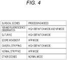
- Fig. 4 is a diagram illustrating an exemplary correspondence table in a case where the single-chip sensor 161-1 is applied in the imaging system of the endoscope 111.
- the correspondence table in Fig. 4 is a table associating surgical scenes and processing modes in a case where the single-chip sensor 161-1 is applied. Note that there are four types of processing modes in a case where the single-chip sensor 161-1 is applied, that is, a normal mode, a high definition mode, a high frame rate (HFR) mode, and a noise reduction (NR) mode. Note that the single-chip pixel shift illustrated in Fig. 3 is performed in the high definition mode among these processing modes.
- the normal mode is a mode in which single-chip pixel shift is not performed and an image (image data) captured at 60 fps is output at 60 fps.
- imaging is performed selectively at each of the pixel positions at which the numeral 1 is described, that is, at pixel G1, pixel R1, pixel B1, and pixel G1, and an output image obtained from image signals output from these pixels is output at 60 fps.
- the high definition mode is a mode in which single-pixel shift is performed and a high definition image (image data) with quadrupled resolution is output at 60 fps.
- the single-chip sensor 161-1 is shifted in units of pixels in 1/60 seconds at the position of pixel in which 1 to 4 numerals are described, and four shots of imaging in total is repeated at each of the positions.
- a high definition image having quadrupled resolution compared with the normal mode or the like is generated and output at 60 fps as an output image. That is, this high definition mode is applied to perform the single-chip pixel shift illustrated in Fig. 3 to output an output image with higher resolution compared with other modes.
- the high definition images obtained in the high definition mode include not merely high definition (HD) video images, but also, for example, ultra high definition (UHD) video images having 4K resolution (for example 3840 in width ⁇ 2160 in height) and 8K resolution (for example 7680 in width x 4320 in height).
- HD high definition
- UHD ultra high definition
- the HFR mode is a mode in which single-chip pixel shift is not performed and the image (image data) is obtained by four shots of imaging during 1/60 second and then output at 240 fps.
- a of Fig. 3 (or B of Fig. 3 ) four shots of imaging are performed selectively at each of the pixel positions at which the numeral 1 is described, that is, at pixel G1, pixel R1, pixel B1, and pixel G1 during 1/60 second, and an output image obtained from the image signal output from these pixels is output at 240 fps. That is, in this HFR mode, the output image can be output at a higher frame rate than in other modes.
- the NR mode is a mode in which single-chip pixel shift is not performed and the four images (image data) are obtained by four shots of imaging during 1/60 second, added and then output at 60 fps.
- a of Fig. 3 (or B of Fig. 3 )
- four shots of imaging are performed selectively at each of the pixel positions at which the numeral 1 is described, that is, at pixel G1, pixel R1, pixel B1, and pixel G1 during 1/60 second, and the output image obtained by adding the image signals output from these pixels is output at 60 fps. That is, in this NR mode, the output image with less noise compared with other modes can be output.
- each of surgical scenes is associated with each of these processing modes. That is, each of the scenes of the narrowband imaging (NBI) and fluorescence observation is associated with the processing mode of either the high definition mode or the NR mode. In addition, the suturing scene is associated with the processing mode of the high definition mode.
- NBI narrowband imaging
- the scope movement scene is associated with the processing mode of the HFR mode.
- the careful stripping scene is associated with the processing mode of the high definition mode, while the normal stripping scene is associated with the processing mode of the HFR mode.
- the normal mode is associated with scenes other than the above-described surgical scenes, that is, scenes other than narrowband imaging, fluorescence observation, suturing, scope movement, careful stripping, and normal stripping scenes.
- the high definition mode and the NR mode are applied to provide high definition images and images with less noise for the scenes where the scope movement is relatively small and the operator wishes to watch in more detail, such as narrowband imaging (NBI), fluorescence observation, careful stripping, and suturing.
- the narrowband imaging (NBI) performs observation with limited amount of light, that is, in a dark condition, leading to a phenomenon of increasing noise in an output image.
- the NR mode it is possible to remove the noise included in the output image.
- the HFR mode is applied to provide an image (high frame rate image) enabling the motion to appear smoother for a scene including a large motion of a scope such as scope movement or for a normal stripping scene.
- this mode for example, fatigue of the operator or assistant can be reduced.
- an appropriate processing mode corresponding to the surgical scene is to be determined by the correspondence table of Fig. 4 .
- the processing mode determination unit 151 of the CCU 101 stores the correspondence table ( Fig. 4 ) beforehand so as to determine the processing mode corresponding to the surgical scene specified by the external signal.
- Fig. 5 is a diagram illustrating an outline of the three-chip pixel shift method.
- the three-chip sensor 161-3 functions such that light passing through the lens is divided into an R component, a G component, and a B component by a prism, so as to be received by a sensor 161-R, a sensor 161-G, and a sensor 161-B, respectively, corresponding to each of the components, allowing an image signal of each of the components to be output from each of the sensors.
- a of Fig. 5 illustrates an exemplary configuration as the three-chip sensor 161-3 including the sensor 161-R for receiving R component light, the sensor 161-G for receiving G component light, and the sensor 161-B for receiving the B component light.
- the three-chip sensor 161 includes dedicated sensors (sensor 161-R, sensor 161-G, and sensor 161-B) applicable for each of the three primary colors of RGB, leading to an advantage of achieving excellent color reproducibility and resolution.
- the sensor 161-R is shifted by 1/2 pixel downward (in column direction) in the drawing and the sensor 161-B is shifted by 1/2 pixel rightward (in row direction) in the drawing with respect to the sensor 161-G as a reference.
- the sensor 161-R and the sensor 161-B are shifted with respect to the sensor 161-G to generate an optical phase shift, and individual planes are simultaneously imaged by the sensor 161-R, the sensor 161-G, and the sensor 161-B in a state where the phases of RGB are shifted, whereby a high definition image can be obtained.
- three-chip sensor 161-3 will be described as an example in the following, it is also allowable to use, for example, three or more sensors (solid-state imaging elements) in the case of using an infrared (IR) component in addition to the RGB components.
- IR infrared
- Fig. 6 is a diagram illustrating an exemplary correspondence table in a case where the three-chip sensor 161-3 is applied in the imaging system of the endoscope 111.
- the correspondence table in Fig. 6 is a table associating surgical scenes and processing modes in a case where the three-chip sensor 161-3 is applied.
- the processing mode in a case where the three-chip sensor 161-3 is applied includes two types of modes, namely, the high definition mode and the HFR mode.
- the high definition mode is a mode of imaging each of RGB planes at a same timing, generating a high definition image from the RGB plane images, and outputting the image as an output image at 60 fps.
- the method for generating a high definition image from each of RGB planes with shifted phases for example, include a method of generating a pixel at a position where no pixel is present using interpolation for each of the plane by a linear filter (Linear Filter) or a general bicubic filter (Bi-Cubic Filter).
- Linear Filter linear Filter
- Bi-Cubic Filter general bicubic filter
- the technique for generating the high definition image exemplified here is illustrative, and other known methods can be used.
- Japanese Patent Laid-Open No. 2000-13670 discloses a technique using a linear filter.
- the high definition image obtained in this high definition mode includes, for example, UHD video images achieving 4K resolution and 8K resolution as well as HD video images. That is, with the high definition mode, it is possible to output an output image with higher resolution than in the HFR mode. Furthermore, details of the high definition mode will be described below with reference to Fig. 7 .
- the HFR mode is a mode of combining images of RBG planes having close imaging time among the RBG plane images captured with shifted imaging timings as a result of imaging of RGB planes with different timings and outputting the combined image as an output image at 120 fps. That is, in this HFR mode, it is possible to output an output image at a higher frame rate than in the high definition mode. Furthermore, details of the HFR mode will be described below with reference to Figs. 7 and 8 .
- NBI narrowband imaging
- fluorescence observation scenes are associated with the processing mode of the high definition mode.
- suturing scene is associated with the processing mode of the high definition mode.
- the scope movement scene is associated with the processing mode of the HFR mode.
- the careful stripping scene is associated with the processing mode of the high definition mode, while the normal stripping scene is associated with the processing mode of the HFR mode.
- the surgical scenes other than the above that is, the surgical scenes not associated with the high definition mode or the HFR mode can be associated with the processing mode of the normal mode.
- the normal mode an output image is output without undergoing any special processing.
- high definition mode is applied to provide high definition images for the scenes where the scope movement is relatively small and the operator wishes to watch in more detail, such as narrowband imaging (NBI), fluorescence observation, careful stripping, and suturing.
- NBI narrowband imaging
- the HFR mode is applied to provide an image (high frame rate image) enabling the motion to appear smoother for a scene including a large motion of a scope such as scope movement or for a normal stripping scene.
- an appropriate processing mode corresponding to the surgical scene is to be determined by the correspondence table of Fig. 6 .
- the processing mode determination unit 151 of the CCU 101 stores the correspondence table ( Fig. 6 ) beforehand so as to determine a processing mode corresponding to the surgical scene specified by the external signal.
- Fig. 7 is a timing chart illustrating RGB signal output timings for each of the processing modes.
- the time direction is a direction from the left side to the right side in the figure.
- a of Fig. 7 is a timing chart illustrating RGB signal output timings for the HFR mode.
- B of Fig. 7 is a timing chart illustrating RGB signal output timings for the high definition mode.
- an image signal corresponding to the R component output from the sensor 161-R is described as an "R signal”.
- an image signal corresponding to the G component output from the sensor 161-G is described as a "G signal”
- an image signal corresponding to the B component output from the sensor 161-B is described as a "B signal”.
- the sensor 161-R, the sensor 161-G, and the sensor 161-B are capable of outputting the R signal, the G signal, and the B signal, respectively, at a same timing because the shutter is in a released state in the three-chip sensor 161-3 in the endoscope 111.
- the high definition mode enables imaging of each of the RGB planes at a same timing, generating a high definition image from the obtained RGB plane images, and outputting the image at 60 fps as an output image. For example, focusing on the period from time t2 to time t6 in the timing chart of B of Fig. 7 , a high definition image (output image) is to be output at the timing of each of time t2, time t4, and time t6.
- a shutter of the endoscope 111 (three-chip sensor 161-3) is controlled to perform imaging with halved exposure time as compared with the case of the high definition mode, and in addition, at shifted timing for each of the RGB planes.
- the RGB plane images captured at close imaging times are to be combined with each other among the RGB plane images captured with shifted imaging timings.
- the G signal obtained in the period from time t1 to time t2 is used, at time t2, so as to combine the R signal and the B signal temporally close to the G signal.
- the B signal obtained in the period from time t2 to time t3 is used to combine the R signal and the G signal temporally close to the B signal.
- the R signal obtained in the period from time t3 to time t4 is used to combine the G signal and the B signal temporally close to the R signal.
- the G signal obtained in the period from time t4 to time t5 is used to combine the R signal and the B signal temporally close to the G signal.
- the B signal obtained in the period from time t5 to time t6 is used to combine the R signal and the G signal temporally close to the B signal.
- the HFR mode is capable of imaging with the halved exposure time compared with the high definition mode to capture each of the RGB planes at different timings, combining RGB plane images having close imaging times among the RGB plane images captured with the shifted imaging timings, and outputting the image at 120 fps. For example, focusing on the period from time t2 to time t6 in the timing chart in A of Fig. 7 , a high frame rate image (output image) is output at a timing of each of the time from time t2 to time t6.
- the output image is output at the time of time t2, time t4, and time t6 among the period from time t2 to time t6 in the high definition mode, while the output image is output at the timing of each of the time points from time t2 to time t6 in the HFR mode. That is, the frame rate (for example, 120 fps) of the output image in the HFR mode is twice the frame rate (for example, 60 fps) of the output image in the high definition mode.
- the exemplary timing chart in Fig. 7 uses the exposure time in the HFR mode being halved compared with the case in the high definition mode, the exposure time can be further reduced to 1/3, 1/4, or the like, to further increase the frame rate of the output image in the HFR mode.
- the image combining unit 152 ( Fig. 2 ) of the CCU 101 has a configuration as illustrated in Fig. 8 .
- the image combining unit 152 corresponding to the HFR mode includes a buffer 181-R, a buffer 181-G, a buffer 181-B, a misalignment detection unit 182, and a misalignment correction unit 183.
- the buffer 181-R is a buffer to hold the R signal output from the sensor 161-R of the endoscope 111.
- the buffer 181-G is a buffer to hold the G signal output from the sensor 161-G of the endoscope 111.
- the buffer 181-B is a buffer to hold the B signal output from the sensor 161-B of the endoscope 111.
- the G signal is held in the buffer 181-G, and the R signal and the B signal temporally close to the G signal are held in the buffer 181-R and the buffer 181-B, respectively.
- the R signal, the G signal, and the B signal respectively held in the buffer 181-R, the buffer 181-G, and the buffer 181-B are read by the misalignment detection unit 182 and the misalignment correction unit 183.
- the misalignment detection unit 182 applies block matching, mutual correlation, or the like, to the R signal, the G signal, and the B signal respectively read from the buffer 181-R, the buffer 181-G, and the buffer 181-B, thereby detecting the misalignment amount of each of the signals for each of the pixels.
- the misalignment detection unit 182 supplies the misalignment amount of each of the detected signals to the misalignment correction unit 183.
- the misalignment correction unit 183 receives inputs of the R signal, the G signal, and the B signal respectively read from the buffer 181-R, the buffer 181-G, and the buffer 181-B, as well as inputs of the misalignment amounts of the individual signals synchronized with these signals, from the misalignment detection unit 182.
- the misalignment correction unit 183 On the basis of the misalignment amount of each of the signals from the misalignment detection unit 182, the misalignment correction unit 183 performs misalignment correction for each of the pixels of the R signal, the G signal, and the B signal respectively read from the buffer 181-R, the buffer 181-G, and the buffer 181-B.
- the misalignment correction unit 183 collectively outputs the R signal, G signal, and B signal aligned with each other by misalignment correction, as an RGB signal (output image).
- the image combining unit 152 ( Fig. 8 ) of the CCU 101 processes the R signal, the G signal, and B signal, buffered in each of the buffers 181, using the misalignment detection unit 182 and the misalignment correction unit 183 so as to perform correction to achieve alignment of the position of the subject that has moved.
- step S101 the processing mode determination unit 151 receives an external signal input from the outside of the CCU 101.
- the external signal to be provided includes, for example, an operation signal corresponding to processing mode switching operation by an operator or the like, a light source switching signal supplied from the light source apparatus 102 ( Fig. 1 ), or a signal indicating power on-off of the energy treatment tool 112.
- step S102 the processing mode determination unit 151 determines a processing mode corresponding to the surgical scene specified by the external signal received in the processing of step S101 with reference to the correspondence table stored beforehand.
- the processing mode determination unit 151 determines the processing mode corresponding to the surgical scene with reference to the correspondence table in Fig. 4 .
- the processing mode determination unit 151 determines the processing mode corresponding to the surgical scene with reference to the correspondence table in Fig. 6 .
- step S103 the sensor control unit 162 controls the sensor 161 on the basis of the processing mode determined by the processing in step S102.
- the sensor 161 outputs an image signal (image signal of an in-vivo image) under the control of the sensor control unit 162.
- the sensor control unit 162 controls the single-chip pixel shift corresponding to the processing mode. More specifically, the sensor control unit 162 turns on the pixel shift processing by the single-chip sensor 161-1 in a case where the processing mode is the high definition mode, while the unit turns off the pixel shift processing by the single-chip sensor 161-1 in a case where the processing mode is set to the mode other than the high definition mode.
- the sensor control unit 162 performs shutter control of the endoscope 111 in accordance with the processing mode. More specifically, in a case where the processing mode is the HFR mode, the sensor control unit 162 controls to halve the exposure time as compared with the case of the high definition mode and controls an imaging timing shift for each of the RGB planes by shutter speeds so as to implement imaging at shifted timing for each of the RGB planes.
- step S104 the image combining unit 152 obtains an image signal output from the endoscope 111 (the sensor 161 thereof) via a camera cable.
- step S105 the image combining unit 152 combines (processes) the image signal obtained by the processing in step S104 on the basis of the processing mode determined by the processing in step S102.
- the output image obtained by the processing of step S105 is output at a predetermined frame rate.
- the image combining unit 152 performs predetermined image processing corresponding to the processing mode. More specifically, in a case where the processing mode is the NR mode, for example, the image combining unit 152 performs image processing of adding image signals obtained by four shots of imaging.
- the image combining unit 152 performs predetermined image processing corresponding to the processing mode. More specifically, in a case where the processing mode is the high definition mode, for example, the image combining unit 152 performs image processing of combining the R signal, the G signal, and the B signal. Moreover, as described above, in a case where the processing mode is the HFR mode, the image combining unit 152 uses the configuration illustrated in Fig. 8 to perform the processing described with reference to Fig. 8 .
- step S106 it is determined whether to finish the processing. In a case where it is determined in step S106 that the processing is not to be finished, the processing returns to step S101 to repeat subsequent processing. In addition, in a case where it is determined in step S106 that the processing is to be finished, the image combining processing of the first embodiment in Fig. 9 is finished.
- the processing mode determination unit 151 refers to the correspondence table (for example, the correspondence table in Fig. 4 or Fig. 6 ) to determine the processing mode corresponding to the surgical scene specified by the external signal, and then, the sensor control unit 162 and the image combining unit 152 perform processing corresponding to the processing mode determined by the processing mode determination unit 151. That is, an appropriate processing mode corresponding to the surgical scene is determined by the correspondence table (for example, the correspondence table in Fig. 4 or Fig. 6 ) and the processing corresponding to the processing mode is performed, making it possible to provide an optimal video image to the operator in accordance with the surgical scenes.
- the correspondence table for example, the correspondence table in Fig. 4 or Fig. 6
- the first embodiment describes a case where a surgical scene is specified by an external signal input from the outside of the CCU 101 to determine the processing mode corresponding to the surgical scene with reference to the correspondence table (for example, the correspondence table in Fig. 4 or Fig. 6 ).
- the correspondence table for example, the correspondence table in Fig. 4 or Fig. 6 .
- it is allowable to use, for example, a method in which a scene recognition processing is performed on an output image (intraoperative image) to specify the surgical scene in accordance with a scene recognition result, other than the method using the external signal.
- Fig. 10 is a diagram illustrating a detailed exemplary configuration of the CCU 101 and the endoscope 111 according to the second embodiment. Note that in the CCU 101 and the endoscope 111 in Fig. 10 , the same reference numerals are given to the blocks corresponding to the CCU 101 and the endoscope 111 in Fig. 2 , and repetitive description thereof will be omitted as appropriate.
- the CCU 101 in Fig. 10 is different from the CCU 101 in Fig. 2 in that a scene recognition unit 153 is provided at a stage following the image combining unit 152, and that a scene recognition result obtained by the scene recognition unit 153 is fed back to the processing mode determination unit 151.
- the endoscope 111 in Fig. 10 and the endoscope 111 in Fig. 2 have a same configuration.
- an output image (image signal) output from the image combining unit 152 is input to the scene recognition unit 153.
- the scene recognition unit 153 performs scene recognition processing on the output image (intraoperative image) from the image combining unit 152.
- scene recognition processing a predetermined scene is recognized from the output image (intraoperative image), and the surgical scene is automatically discriminated.
- a scene recognition result (surgical scene discrimination result) obtained in the scene recognition processing is fed back to the processing mode determination unit 151.
- the scene recognition result (surgical scene discrimination result) fed back from the scene recognition unit 153 to the processing mode determination unit 151 can include the following information.
- a surgical scene discrimination result as being narrowband imaging (NBI), fluorescence observation, or normal observation, corresponding to distribution analysis of RGB histograms on an output image (intraoperative image).
- NBI narrowband imaging
- fluorescence observation or normal observation
- a surgical scene discrimination result as being a suture corresponding to detection of a thread or a suture needle included in an output image (intraoperative image).
- a surgical scene discrimination result as being a scope movement corresponding to detection of a frame difference or motion vector of an output image (intraoperative image).
- a surgical scene discrimination result as being stripping (normal stripping or careful stripping) corresponding to detection of the forceps 135 included in the output image (intraoperative image) and motion detection of the forceps 135.
- surgical scene discrimination results listed herein are illustrative, and for example, it is allowable to cause another scene recognition result obtained using known image analysis processing to be fed back to the processing mode determination unit 151.
- the scene recognition result (discrimination result of the surgical scene) corresponding to the output image (intraoperative image) is input from the scene recognition unit 153 to the processing mode determination unit 151 at a predetermined timing.
- the processing mode determination unit 151 determines the processing mode corresponding to a surgical scene specified by the scene recognition result (surgical scene discrimination result) with reference to the correspondence table stored beforehand (for example, the correspondence table in Fig. 4 or Fig. 6 ).
- the processing mode determination unit 151 supplies the determined processing mode to the image combining unit 152 and to the sensor control unit 162 of the endoscope 111.
- the sensor control unit 162 controls the sensor 161 on the basis of the processing mode supplied from the processing mode determination unit 151. Moreover, on the basis of the processing mode supplied from the processing mode determination unit 151, the image combining unit 152 performs predetermined image processing on an image signal supplied from the endoscope 111 (the sensor control unit 162 thereof) via a camera cable.
- step S151 it is determined whether processing of the endoscopic surgery system 10 has been started. In a case where it is determined in step S151 that the processing has been started, the processing proceeds to step S152.
- step S152 the processing mode determination unit 151 determines an initial processing mode, and supplies the determined initial processing mode to the image combining unit 152 and the sensor control unit 162.
- the initial processing mode set beforehand is to be determined because the scene recognition unit 153 cannot obtain an output image (intraoperative image) from the image combining unit 152 immediately after the processing is started in the endoscopic surgery system 10 (the CCU 101 thereof), and that the scene recognition result (surgical scene discrimination result) cannot be fed back to the processing mode determination unit 151.
- step S151 the processing proceeds to step S153.
- step S153 the scene recognition unit 153 performs scene recognition processing on an output image (intraoperative image) corresponding to an image signal from the image combining unit 152.
- step S153 a predetermined scene from the output image (intraoperative image) is recognized and the surgical scene is automatically discriminated. Subsequently, the scene recognition result (surgical scene discrimination result) obtained in the processing of step S153 is fed back to the processing mode determination unit 151.
- step S154 the processing mode determination unit 151 determines a processing mode corresponding to the surgical scene specified by the scene recognition result (surgical scene discrimination result) obtained in the processing of step S153, with reference to the correspondence table stored beforehand.
- the processing mode determination unit 151 determines the processing mode corresponding to the surgical scene discrimination result obtained as a feedback, with reference to the correspondence table in Fig. 4 .
- the processing mode determination unit 151 determines the processing mode corresponding to the surgical scene discrimination result obtained as a feedback, with reference to the correspondence table in Fig. 6 .
- the sensor control unit 162 controls the sensor 161 on the basis of the processing mode determined by the processing in step S154, similarly to the steps S103 to S105 of Fig. 9 , and the image signals are combined (processed) by the image combining unit 152 on the basis of the processing mode determined by the processing in step S154.
- the output image obtained in the processing of step S157 is output at a predetermined frame rate.
- step S158 it is determined whether to finish the processing. In a case where it is determined in step S158 that the processing is not to be finished, the processing returns to step S151 to repeat the subsequent processing. In addition, in a case where it is determined in step S158 that the processing is to be finished, the image combining processing of the second embodiment in Fig. 11 is finished.
- the processing mode determination unit 151 refers to the correspondence table (for example, the correspondence table in Fig. 4 or Fig. 6 ) to determine the processing mode corresponding to the surgical scene specified by the scene recognition result (surgical scene discrimination result), and then, the sensor control unit 162 and the image combining unit 152 perform processing corresponding to the processing mode determined by the processing mode determination unit 151. That is, an appropriate processing mode corresponding to the surgical scene is determined by the correspondence table (for example, the correspondence table in Fig. 4 or Fig. 6 ) and the processing corresponding to the processing mode is performed, making it possible to provide an optimal video image to the operator in accordance with the surgical scenes.
- the correspondence table for example, the correspondence table in Fig. 4 or Fig. 6
- the processing mode determination method may include, for example, a method of determining an appropriate processing mode in accordance with a surgery plan created beforehand. Specifically, for example, it is allowable to perform preliminary planning of the details of a surgery using a three-dimensional model to associate each of surgical sites (affected sites) with a processing mode (for example, associating the high definition mode with a treatment for a certain affected site). Under this planning, in a case where future implementation of the treatment for the target surgical site (affected site) is detected from an output image (intraoperative image), it is sufficient to shift to the processing mode associated with the surgical site (affected site).
- a series of processing (for example, image combining processing) described above can be executed in hardware or with software.
- a program included in the software is installed in a computer.
- the computer includes, for example, a computer incorporated in a dedicated hardware, and a general-purpose personal computer on which various types of functions can be executed.
- Fig. 12 is a block diagram illustrating an exemplary configuration of hardware of a computer on which the series of processing described above is executed by a program.
- a central processing unit (CPU) 201 a read only memory (ROM) 202, a random access memory (RAM) 203 are interconnected with each other via a bus 204.
- the bus 204 is further connected with an input/output interface 205.
- the input/output interface 205 is connected with an input unit 206, an output unit 207, a recording unit 208, a communication unit 209, and a drive 210.
- the input unit 206 includes a key board, a mouse, a microphone, and the like.
- the output unit 207 includes a display, a speaker, and the like.
- the recording unit 208 includes hardware, a non-volatile memory, and the like.
- the communication unit 209 includes a network interface and the like.
- the drive 210 drives a removable medium 211 including a magnetic disk, an optical disk, a magneto-optical disk, a semiconductor memory, or the like.
- the series of above-described processing is executed by operation such that the CPU 201 loads, for example, a program stored in the recording unit 208 onto the RAM 203 via the input/output interface 205 and the bus 204 and executes the program.
- the program executed by the computer 200 can be recorded, for example, in the removable medium 211 such as a package medium and be provided.
- the program can be provided via a wired or wireless transmission medium including a local area network, an Internet, and digital satellite broadcasting.
- the program can be installed in the recording unit 208 via the input/output interface 205, by attaching the removable medium 211 to the drive 210.
- the program can be received at the communication unit 209 via a wired or wireless transmission medium and be installed in the recording unit 208.
- the program can be installed in the ROM 202 or the recording unit 208 beforehand.
- the program executed by the computer 200 may be a program processed in a time series in an order described in the present description, or can be a program processed in parallel or in a required timing such as being called.
- processing steps describing a program required for causing the computer 200 to execute various types of processing are not necessarily processed in sequentially in an order described in the flowchart.
- the processing steps may include steps executed in parallel or individually (for example, parallel processing or processing by objects).
- the program can be processed by one computer or can be handled with distributed processing by a plurality of computers. Furthermore, the program can be transferred to a remote computer and be executed.
- the system represents a set of multiple constituents (devices, modules (parts), or the like).
- all the constituents may be in a same housing but they do not have to be in the same housing.
- a plurality of apparatuses, housed in separate housings, connected via a network can be a system.
- An apparatus in which a plurality of modules is housed in one housing can also be a system.
- embodiments of the present technology are not limited to the above-described embodiments but can be modified in a variety of ways within a scope of the present technology.
- the present technology can be configured as a form of cloud computing in which one function is shared in cooperation for processing among a plurality of devices via a network.
- each of steps described in the above flowcharts can be executed on one apparatus or shared by a plurality of apparatuses for processing.
- the plurality of stages of processing included in the one step can be executed on one apparatus or can be shared by a plurality of apparatuses.
Landscapes
- Life Sciences & Earth Sciences (AREA)
- Health & Medical Sciences (AREA)
- Engineering & Computer Science (AREA)
- Surgery (AREA)
- Physics & Mathematics (AREA)
- Biomedical Technology (AREA)
- Medical Informatics (AREA)
- Nuclear Medicine, Radiotherapy & Molecular Imaging (AREA)
- Optics & Photonics (AREA)
- Pathology (AREA)
- Radiology & Medical Imaging (AREA)
- Veterinary Medicine (AREA)
- Public Health (AREA)
- Heart & Thoracic Surgery (AREA)
- Biophysics (AREA)
- Molecular Biology (AREA)
- Animal Behavior & Ethology (AREA)
- General Health & Medical Sciences (AREA)
- Signal Processing (AREA)
- General Physics & Mathematics (AREA)
- Theoretical Computer Science (AREA)
- Multimedia (AREA)
- Endoscopes (AREA)
- Studio Devices (AREA)
Claims (14)
- Informationsverarbeitungsvorrichtung, umfassend:eine Verarbeitungsmodusbestimmungseinheit (151), die gemäß Operationsszenen einen einer Vielzahl von Verarbeitungsmodi für ein von einem Bildgebungsgerät, das ein Bildgebungselement (161) aufweist, das so angeordnet ist, dass es Pixelverschiebungsverarbeitung ermöglicht, erfasstes In-vivo-Bild bestimmt; undeine Verarbeitungseinheit (201), die eine Bildausgabe des Bildgebungsgeräts gemäß dem einen der Vielzahl von Verarbeitungsmodi verarbeitet;dadurch gekennzeichnet, dassdie Vielzahl von Verarbeitungsmodi einen Modus beinhaltet, der in der Lage ist, durch die Pixelverschiebungsverarbeitung ein Bild mit hoher Auflösung bereitzustellen, das eine höhere Auflösung aufweist als das vom Bildgebungselement erfasste In-vivo-Bild.
- Informationsverarbeitungsvorrichtung nach Anspruch 1,
wobei das Bildgebungsgerät eine Steuereinheit aufweist, die das Bildgebungselement gemäß dem einen der Vielzahl von Verarbeitungsmodi steuert, und
die Verarbeitungsmodusbestimmungseinheit den Verarbeitungsmodus an die Steuereinheit übermittelt. - Informationsverarbeitungsvorrichtung nach Anspruch 1,
wobei die Vielzahl von Verarbeitungsmodi ferner zumindest einen von einem Modus, der zur Bereitstellung eines Bilds mit weniger Rauschen als in dem vom Bildgebungselement erfassten In-vivo-Bild befähigt ist, und von einem Modus, der zur Bereitstellung eines Bilds befähigt ist, in dem eine Bewegung glatter erscheint als in dem vom Bildgebungselement erfassten In-vivo-Bild, beinhaltet. - Informationsverarbeitungsvorrichtung nach Anspruch 1,
wobei das Bildgebungsgerät mindestens drei Bildgebungselemente aufweist. - Informationsverarbeitungsvorrichtung nach Anspruch 1,
wobei die Modusbestimmungseinheit den einen der Vielzahl von Verarbeitungsmodi gemäß einem externen Signaleingang von einer Außenseite bestimmt. - Informationsverarbeitungsvorrichtung nach Anspruch 5,
wobei die Modusbestimmungseinheit den einen der Vielzahl von Verarbeitungsmodi gemäß eines von einer Bedienungsperson durchgeführten Vorgangs zum Umschalten des Verarbeitungsmodus bestimmt. - Informationsverarbeitungsvorrichtung nach Anspruch 5,
wobei die Modusbestimmungseinheit den einen der Vielzahl von Verarbeitungsmodi gemäß einem Signal, das darauf hinweist, dass ein Behandlungswerkzeug an- oder abgeschaltet ist, das von einer Behandlungswerkzeugvorrichtung ausgegeben wird, bestimmt. - Informationsverarbeitungsvorrichtung nach Anspruch 5,
wobei die Modusbestimmungseinheit den einen der Vielzahl von Verarbeitungsmodi gemäß einem Lichtquellenschaltsignal, das von einer Lichtquellenvorrichtung ausgegeben wurde, bestimmt. - Informationsverarbeitungsvorrichtung nach Anspruch 1,
wobei die Modusbestimmungseinheit den einen der Vielzahl von Verarbeitungsmodi gemäß einem zuvor erstellten Operationsplan bestimmt. - Informationsverarbeitungsvorrichtung nach Anspruch 9,
wobei die Modusbestimmungseinheit den einen der Vielzahl von Verarbeitungsmodi gemäß dem Verarbeitungsmodus für jede der zuvor im Operationsplan geplanten Operationsstellen bestimmt. - Informationsverarbeitungsvorrichtung nach Anspruch 1,
ferner umfassend eine Szenenerkennungseinheit, die eine vorbestimmte Szene auf Basis der Bildausgabe des Bildgebungsgeräts erkennt,
wobei die Modusbestimmungseinheit den einen der Vielzahl von Verarbeitungsmodi auf Basis eines von der Szenenerkennungseinheit erhaltenen Erkennungsresultats bestimmt. - Informationsverarbeitungsvorrichtung nach Anspruch 1,
wobei die Modusbestimmungseinheit eine Tabelle speichert, die die Operationsszene mit dem Verarbeitungsmodus in Zusammenhang bringt, und
den einen der Vielzahl von Verarbeitungsmodi mit Bezug auf die Tabelle bestimmt. - Informationsverarbeitungsverfahren einer Informationsverarbeitungsvorrichtung,
wobei das Verfahren die folgenden Schritte umfasst:Bestimmen, mit der Informationsverarbeitungsvorrichtung gemäß einer Operationsszene, einen einer Vielzahl von Verarbeitungsmodi für ein von einem Bildgebungsgerät, das ein Bildgebungselement aufweist, das so angeordnet ist, dass es Pixelverschiebungsverarbeitung ermöglicht, erfasstes In-vivo-Bild; undVerarbeiten einer Bildausgabe des Bildgebungsgeräts durch die Informationsverarbeitungsvorrichtung gemäß dem einen der Vielzahl von Verarbeitungsmodi;dadurch gekennzeichnet, dassdie Vielzahl von Verarbeitungsmodi einen Modus beinhaltet, der in der Lage ist, durch die Pixelverschiebungsverarbeitung ein Bild mit hoher Auflösung bereitzustellen, das eine höhere Auflösung aufweist als das mit dem Bildgebungselement erfasste In-vivo-Bild. - Endoskopsystem, umfassend ein Endoskop und die Informationsverarbeitungsvorrichtung nach Anspruch 1,
wobei das Endoskop das Folgende aufweist:ein Bildgebungselement, das so angeordnet ist, dass es Pixelverschiebungsverarbeitung erlaubt; undeine Steuereinheit, die das Bildgebungselement steuert,wobei die Informationsverarbeitungsvorrichtung ferner das Folgende umfasst:
die Steuereinheit steuert das Bildgebungselement gemäß dem einen der Vielzahl von Verarbeitungsmodi.
Applications Claiming Priority (2)
| Application Number | Priority Date | Filing Date | Title |
|---|---|---|---|
| JP2015213767 | 2015-10-30 | ||
| PCT/JP2016/080496 WO2017073361A1 (ja) | 2015-10-30 | 2016-10-14 | 情報処理装置、情報処理方法、及び、内視鏡システム |
Publications (3)
| Publication Number | Publication Date |
|---|---|
| EP3369362A1 EP3369362A1 (de) | 2018-09-05 |
| EP3369362A4 EP3369362A4 (de) | 2018-12-19 |
| EP3369362B1 true EP3369362B1 (de) | 2020-01-08 |
Family
ID=58631411
Family Applications (1)
| Application Number | Title | Priority Date | Filing Date |
|---|---|---|---|
| EP16859591.6A Active EP3369362B1 (de) | 2015-10-30 | 2016-10-14 | Informationsverarbeitungsvorrichtung, informationsverarbeitungsverfahren und endoskopsystem |
Country Status (5)
| Country | Link |
|---|---|
| US (2) | US10722106B2 (de) |
| EP (1) | EP3369362B1 (de) |
| JP (1) | JP6888551B2 (de) |
| CN (1) | CN108348143B (de) |
| WO (1) | WO2017073361A1 (de) |
Families Citing this family (10)
| Publication number | Priority date | Publication date | Assignee | Title |
|---|---|---|---|---|
| JP2017099616A (ja) * | 2015-12-01 | 2017-06-08 | ソニー株式会社 | 手術用制御装置、手術用制御方法、およびプログラム、並びに手術システム |
| JP7048628B2 (ja) | 2016-11-28 | 2022-04-05 | アダプティブエンドウ エルエルシー | 分離可能使い捨てシャフト付き内視鏡 |
| EP3998931A4 (de) * | 2019-07-16 | 2023-04-19 | Docbot, Inc. | Echtzeit-einsatz von maschinenlernsystemen |
| WO2021097332A1 (en) * | 2019-11-15 | 2021-05-20 | Intuitive Surgical Operations, Inc. | Scene perception systems and methods |
| USD1018844S1 (en) | 2020-01-09 | 2024-03-19 | Adaptivendo Llc | Endoscope handle |
| USD1051380S1 (en) | 2020-11-17 | 2024-11-12 | Adaptivendo Llc | Endoscope handle |
| USD1070082S1 (en) | 2021-04-29 | 2025-04-08 | Adaptivendo Llc | Endoscope handle |
| USD1031035S1 (en) | 2021-04-29 | 2024-06-11 | Adaptivendo Llc | Endoscope handle |
| USD1066659S1 (en) | 2021-09-24 | 2025-03-11 | Adaptivendo Llc | Endoscope handle |
| US12239409B2 (en) | 2022-02-28 | 2025-03-04 | Visionsense Ltd. | Fluorescence imaging camera assembly for open surgery |
Family Cites Families (17)
| Publication number | Priority date | Publication date | Assignee | Title |
|---|---|---|---|---|
| JP2005305046A (ja) | 2004-04-26 | 2005-11-04 | Olympus Corp | 手術用観察システム |
| JP2006269992A (ja) * | 2005-03-25 | 2006-10-05 | Yamagata Casio Co Ltd | 画像データ生成方法及びそれを用いた部品搭載装置 |
| JP2007020727A (ja) * | 2005-07-13 | 2007-02-01 | Olympus Medical Systems Corp | 画像処理装置 |
| US9262697B2 (en) * | 2006-09-25 | 2016-02-16 | Cambridge Research & Instrumentation, Inc. | Sample imaging and classification |
| JP2009225933A (ja) | 2008-03-21 | 2009-10-08 | Fujifilm Corp | カプセル内視鏡システム及びカプセル内視鏡の動作制御方法 |
| JP5466876B2 (ja) | 2009-05-14 | 2014-04-09 | オリンパス株式会社 | 画像取得装置、画像取得装置の制御方法、及び顕微鏡システム |
| JP5379647B2 (ja) | 2009-10-29 | 2013-12-25 | オリンパス株式会社 | 撮像装置、及び、画像生成方法 |
| JP5415973B2 (ja) * | 2010-01-25 | 2014-02-12 | オリンパス株式会社 | 撮像装置、内視鏡システム及び撮像装置の作動方法 |
| JP5715372B2 (ja) * | 2010-10-15 | 2015-05-07 | オリンパス株式会社 | 画像処理装置、画像処理装置の作動方法及び内視鏡装置 |
| JP5623348B2 (ja) * | 2011-07-06 | 2014-11-12 | 富士フイルム株式会社 | 内視鏡システム、内視鏡システムのプロセッサ装置、及び内視鏡システムの作動方法 |
| JP5530577B1 (ja) * | 2012-09-03 | 2014-06-25 | オリンパスメディカルシステムズ株式会社 | 走査型内視鏡システム |
| JP6080505B2 (ja) * | 2012-11-06 | 2017-02-15 | キヤノン株式会社 | 像振れ補正装置およびその制御方法 |
| US20150105758A1 (en) * | 2013-10-15 | 2015-04-16 | Olympus Medical Systems Corp. | Method for endoscopic treatment |
| JP6460631B2 (ja) * | 2014-02-19 | 2019-01-30 | オリンパス株式会社 | 撮像装置、内視鏡装置及び顕微鏡装置 |
| JP6407643B2 (ja) * | 2014-09-19 | 2018-10-17 | キヤノンメディカルシステムズ株式会社 | 画像処理装置、画像処理システム及び画像処理方法 |
| JP6490196B2 (ja) * | 2015-04-06 | 2019-03-27 | オリンパス株式会社 | 画像処理装置、生体観察装置および画像処理方法 |
| EP3354188A4 (de) * | 2015-09-24 | 2019-04-17 | Olympus Corporation | Endoskopvorrichtung |
-
2016
- 2016-10-14 US US15/761,438 patent/US10722106B2/en active Active
- 2016-10-14 WO PCT/JP2016/080496 patent/WO2017073361A1/ja not_active Ceased
- 2016-10-14 EP EP16859591.6A patent/EP3369362B1/de active Active
- 2016-10-14 CN CN201680061702.8A patent/CN108348143B/zh active Active
- 2016-10-14 JP JP2017547730A patent/JP6888551B2/ja active Active
-
2020
- 2020-07-15 US US16/929,693 patent/US11744440B2/en active Active
Also Published As
| Publication number | Publication date |
|---|---|
| EP3369362A1 (de) | 2018-09-05 |
| US20200345220A1 (en) | 2020-11-05 |
| CN108348143A (zh) | 2018-07-31 |
| US20190046020A1 (en) | 2019-02-14 |
| US11744440B2 (en) | 2023-09-05 |
| WO2017073361A1 (ja) | 2017-05-04 |
| CN108348143B (zh) | 2020-11-03 |
| JP6888551B2 (ja) | 2021-06-16 |
| JPWO2017073361A1 (ja) | 2018-08-16 |
| US10722106B2 (en) | 2020-07-28 |
| EP3369362A4 (de) | 2018-12-19 |
Similar Documents
| Publication | Publication Date | Title |
|---|---|---|
| US11744440B2 (en) | Information processing apparatus, information processing method, and endoscope system for processing images based on surgical scenes | |
| US10867367B2 (en) | Image processing apparatus, image processing method, computer-readable recording medium, and endoscope apparatus | |
| US20140015933A1 (en) | Image processing apparatus, imaging system, and image processing system | |
| CN109863755B (zh) | 信号处理设备、方法和程序 | |
| US20210019921A1 (en) | Image processing device, image processing method, and program | |
| CN107105987B (zh) | 图像处理装置及其工作方法、记录介质和内窥镜装置 | |
| US20250359760A1 (en) | Medical imaging systems and methods | |
| US11064144B2 (en) | Imaging element, imaging apparatus, and electronic equipment | |
| US20220030174A1 (en) | Optical scope system for capturing an image of a scene | |
| CN107113405A (zh) | 图像处理装置、图像处理装置的工作方法、图像处理装置的工作程序和内窥镜装置 | |
| CN114651439A (zh) | 信息处理系统、内窥镜系统、已学习模型、信息存储介质及信息处理方法 | |
| JPWO2016072288A1 (ja) | 内視鏡装置、および、内視鏡装置の動作方法、並びにプログラム | |
| WO2015194204A1 (ja) | 内視鏡装置 | |
| WO2016084257A1 (ja) | 内視鏡装置 | |
| JP2017099616A (ja) | 手術用制御装置、手術用制御方法、およびプログラム、並びに手術システム | |
| US10542866B2 (en) | Medical imaging device | |
| CN110945399B (zh) | 信号处理设备、成像设备、信号处理方法和存储器 | |
| US11676242B2 (en) | Image processing apparatus and image processing method | |
| US9589103B2 (en) | Medical image recording/reproducing apparatus, medical image recording/reproducing method and computer readable medium | |
| US10945592B2 (en) | Medical imaging apparatus and endoscope apparatus | |
| WO2017082091A1 (ja) | 手術システム、手術用制御方法、およびプログラム | |
| JP7068438B2 (ja) | 画像処理装置、内視鏡システム、画像処理方法およびプログラム | |
| JP6042798B2 (ja) | 画像処理装置及び内視鏡システム | |
| JP5317869B2 (ja) | 眼科撮影システム | |
| US20240422428A1 (en) | Medical image processing device and medical image processing system |
Legal Events
| Date | Code | Title | Description |
|---|---|---|---|
| STAA | Information on the status of an ep patent application or granted ep patent |
Free format text: STATUS: THE INTERNATIONAL PUBLICATION HAS BEEN MADE |
|
| PUAI | Public reference made under article 153(3) epc to a published international application that has entered the european phase |
Free format text: ORIGINAL CODE: 0009012 |
|
| STAA | Information on the status of an ep patent application or granted ep patent |
Free format text: STATUS: REQUEST FOR EXAMINATION WAS MADE |
|
| 17P | Request for examination filed |
Effective date: 20180423 |
|
| AK | Designated contracting states |
Kind code of ref document: A1 Designated state(s): AL AT BE BG CH CY CZ DE DK EE ES FI FR GB GR HR HU IE IS IT LI LT LU LV MC MK MT NL NO PL PT RO RS SE SI SK SM TR |
|
| AX | Request for extension of the european patent |
Extension state: BA ME |
|
| A4 | Supplementary search report drawn up and despatched |
Effective date: 20181121 |
|
| RIC1 | Information provided on ipc code assigned before grant |
Ipc: A61B 1/04 20060101AFI20181115BHEP |
|
| DAV | Request for validation of the european patent (deleted) | ||
| DAX | Request for extension of the european patent (deleted) | ||
| GRAP | Despatch of communication of intention to grant a patent |
Free format text: ORIGINAL CODE: EPIDOSNIGR1 |
|
| STAA | Information on the status of an ep patent application or granted ep patent |
Free format text: STATUS: GRANT OF PATENT IS INTENDED |
|
| RIC1 | Information provided on ipc code assigned before grant |
Ipc: A61B 1/04 20060101AFI20190719BHEP |
|
| INTG | Intention to grant announced |
Effective date: 20190814 |
|
| GRAS | Grant fee paid |
Free format text: ORIGINAL CODE: EPIDOSNIGR3 |
|
| GRAA | (expected) grant |
Free format text: ORIGINAL CODE: 0009210 |
|
| STAA | Information on the status of an ep patent application or granted ep patent |
Free format text: STATUS: THE PATENT HAS BEEN GRANTED |
|
| AK | Designated contracting states |
Kind code of ref document: B1 Designated state(s): AL AT BE BG CH CY CZ DE DK EE ES FI FR GB GR HR HU IE IS IT LI LT LU LV MC MK MT NL NO PL PT RO RS SE SI SK SM TR |
|
| REG | Reference to a national code |
Ref country code: GB Ref legal event code: FG4D |
|
| REG | Reference to a national code |
Ref country code: CH Ref legal event code: EP |
|
| REG | Reference to a national code |
Ref country code: DE Ref legal event code: R096 Ref document number: 602016028096 Country of ref document: DE |
|
| REG | Reference to a national code |
Ref country code: IE Ref legal event code: FG4D |
|
| REG | Reference to a national code |
Ref country code: AT Ref legal event code: REF Ref document number: 1221639 Country of ref document: AT Kind code of ref document: T Effective date: 20200215 |
|
| REG | Reference to a national code |
Ref country code: NL Ref legal event code: MP Effective date: 20200108 |
|
| REG | Reference to a national code |
Ref country code: LT Ref legal event code: MG4D |
|
| PG25 | Lapsed in a contracting state [announced via postgrant information from national office to epo] |
Ref country code: NO Free format text: LAPSE BECAUSE OF FAILURE TO SUBMIT A TRANSLATION OF THE DESCRIPTION OR TO PAY THE FEE WITHIN THE PRESCRIBED TIME-LIMIT Effective date: 20200408 Ref country code: RS Free format text: LAPSE BECAUSE OF FAILURE TO SUBMIT A TRANSLATION OF THE DESCRIPTION OR TO PAY THE FEE WITHIN THE PRESCRIBED TIME-LIMIT Effective date: 20200108 Ref country code: FI Free format text: LAPSE BECAUSE OF FAILURE TO SUBMIT A TRANSLATION OF THE DESCRIPTION OR TO PAY THE FEE WITHIN THE PRESCRIBED TIME-LIMIT Effective date: 20200108 Ref country code: LT Free format text: LAPSE BECAUSE OF FAILURE TO SUBMIT A TRANSLATION OF THE DESCRIPTION OR TO PAY THE FEE WITHIN THE PRESCRIBED TIME-LIMIT Effective date: 20200108 Ref country code: NL Free format text: LAPSE BECAUSE OF FAILURE TO SUBMIT A TRANSLATION OF THE DESCRIPTION OR TO PAY THE FEE WITHIN THE PRESCRIBED TIME-LIMIT Effective date: 20200108 Ref country code: PT Free format text: LAPSE BECAUSE OF FAILURE TO SUBMIT A TRANSLATION OF THE DESCRIPTION OR TO PAY THE FEE WITHIN THE PRESCRIBED TIME-LIMIT Effective date: 20200531 |
|
| PG25 | Lapsed in a contracting state [announced via postgrant information from national office to epo] |
Ref country code: BG Free format text: LAPSE BECAUSE OF FAILURE TO SUBMIT A TRANSLATION OF THE DESCRIPTION OR TO PAY THE FEE WITHIN THE PRESCRIBED TIME-LIMIT Effective date: 20200408 Ref country code: SE Free format text: LAPSE BECAUSE OF FAILURE TO SUBMIT A TRANSLATION OF THE DESCRIPTION OR TO PAY THE FEE WITHIN THE PRESCRIBED TIME-LIMIT Effective date: 20200108 Ref country code: LV Free format text: LAPSE BECAUSE OF FAILURE TO SUBMIT A TRANSLATION OF THE DESCRIPTION OR TO PAY THE FEE WITHIN THE PRESCRIBED TIME-LIMIT Effective date: 20200108 Ref country code: IS Free format text: LAPSE BECAUSE OF FAILURE TO SUBMIT A TRANSLATION OF THE DESCRIPTION OR TO PAY THE FEE WITHIN THE PRESCRIBED TIME-LIMIT Effective date: 20200508 Ref country code: GR Free format text: LAPSE BECAUSE OF FAILURE TO SUBMIT A TRANSLATION OF THE DESCRIPTION OR TO PAY THE FEE WITHIN THE PRESCRIBED TIME-LIMIT Effective date: 20200409 Ref country code: HR Free format text: LAPSE BECAUSE OF FAILURE TO SUBMIT A TRANSLATION OF THE DESCRIPTION OR TO PAY THE FEE WITHIN THE PRESCRIBED TIME-LIMIT Effective date: 20200108 |
|
| REG | Reference to a national code |
Ref country code: DE Ref legal event code: R097 Ref document number: 602016028096 Country of ref document: DE |
|
| PG25 | Lapsed in a contracting state [announced via postgrant information from national office to epo] |
Ref country code: CZ Free format text: LAPSE BECAUSE OF FAILURE TO SUBMIT A TRANSLATION OF THE DESCRIPTION OR TO PAY THE FEE WITHIN THE PRESCRIBED TIME-LIMIT Effective date: 20200108 Ref country code: RO Free format text: LAPSE BECAUSE OF FAILURE TO SUBMIT A TRANSLATION OF THE DESCRIPTION OR TO PAY THE FEE WITHIN THE PRESCRIBED TIME-LIMIT Effective date: 20200108 Ref country code: SK Free format text: LAPSE BECAUSE OF FAILURE TO SUBMIT A TRANSLATION OF THE DESCRIPTION OR TO PAY THE FEE WITHIN THE PRESCRIBED TIME-LIMIT Effective date: 20200108 Ref country code: DK Free format text: LAPSE BECAUSE OF FAILURE TO SUBMIT A TRANSLATION OF THE DESCRIPTION OR TO PAY THE FEE WITHIN THE PRESCRIBED TIME-LIMIT Effective date: 20200108 Ref country code: EE Free format text: LAPSE BECAUSE OF FAILURE TO SUBMIT A TRANSLATION OF THE DESCRIPTION OR TO PAY THE FEE WITHIN THE PRESCRIBED TIME-LIMIT Effective date: 20200108 Ref country code: SM Free format text: LAPSE BECAUSE OF FAILURE TO SUBMIT A TRANSLATION OF THE DESCRIPTION OR TO PAY THE FEE WITHIN THE PRESCRIBED TIME-LIMIT Effective date: 20200108 Ref country code: ES Free format text: LAPSE BECAUSE OF FAILURE TO SUBMIT A TRANSLATION OF THE DESCRIPTION OR TO PAY THE FEE WITHIN THE PRESCRIBED TIME-LIMIT Effective date: 20200108 |
|
| PLBE | No opposition filed within time limit |
Free format text: ORIGINAL CODE: 0009261 |
|
| STAA | Information on the status of an ep patent application or granted ep patent |
Free format text: STATUS: NO OPPOSITION FILED WITHIN TIME LIMIT |
|
| REG | Reference to a national code |
Ref country code: AT Ref legal event code: MK05 Ref document number: 1221639 Country of ref document: AT Kind code of ref document: T Effective date: 20200108 |
|
| 26N | No opposition filed |
Effective date: 20201009 |
|
| PG25 | Lapsed in a contracting state [announced via postgrant information from national office to epo] |
Ref country code: AT Free format text: LAPSE BECAUSE OF FAILURE TO SUBMIT A TRANSLATION OF THE DESCRIPTION OR TO PAY THE FEE WITHIN THE PRESCRIBED TIME-LIMIT Effective date: 20200108 Ref country code: IT Free format text: LAPSE BECAUSE OF FAILURE TO SUBMIT A TRANSLATION OF THE DESCRIPTION OR TO PAY THE FEE WITHIN THE PRESCRIBED TIME-LIMIT Effective date: 20200108 |
|
| PG25 | Lapsed in a contracting state [announced via postgrant information from national office to epo] |
Ref country code: PL Free format text: LAPSE BECAUSE OF FAILURE TO SUBMIT A TRANSLATION OF THE DESCRIPTION OR TO PAY THE FEE WITHIN THE PRESCRIBED TIME-LIMIT Effective date: 20200108 Ref country code: SI Free format text: LAPSE BECAUSE OF FAILURE TO SUBMIT A TRANSLATION OF THE DESCRIPTION OR TO PAY THE FEE WITHIN THE PRESCRIBED TIME-LIMIT Effective date: 20200108 |
|
| REG | Reference to a national code |
Ref country code: CH Ref legal event code: PL |
|
| GBPC | Gb: european patent ceased through non-payment of renewal fee |
Effective date: 20201014 |
|
| PG25 | Lapsed in a contracting state [announced via postgrant information from national office to epo] |
Ref country code: MC Free format text: LAPSE BECAUSE OF FAILURE TO SUBMIT A TRANSLATION OF THE DESCRIPTION OR TO PAY THE FEE WITHIN THE PRESCRIBED TIME-LIMIT Effective date: 20200108 Ref country code: LU Free format text: LAPSE BECAUSE OF NON-PAYMENT OF DUE FEES Effective date: 20201014 |
|
| REG | Reference to a national code |
Ref country code: BE Ref legal event code: MM Effective date: 20201031 |
|
| PG25 | Lapsed in a contracting state [announced via postgrant information from national office to epo] |
Ref country code: GB Free format text: LAPSE BECAUSE OF NON-PAYMENT OF DUE FEES Effective date: 20201014 Ref country code: BE Free format text: LAPSE BECAUSE OF NON-PAYMENT OF DUE FEES Effective date: 20201031 Ref country code: CH Free format text: LAPSE BECAUSE OF NON-PAYMENT OF DUE FEES Effective date: 20201031 Ref country code: LI Free format text: LAPSE BECAUSE OF NON-PAYMENT OF DUE FEES Effective date: 20201031 |
|
| PG25 | Lapsed in a contracting state [announced via postgrant information from national office to epo] |
Ref country code: IE Free format text: LAPSE BECAUSE OF NON-PAYMENT OF DUE FEES Effective date: 20201014 |
|
| PG25 | Lapsed in a contracting state [announced via postgrant information from national office to epo] |
Ref country code: TR Free format text: LAPSE BECAUSE OF FAILURE TO SUBMIT A TRANSLATION OF THE DESCRIPTION OR TO PAY THE FEE WITHIN THE PRESCRIBED TIME-LIMIT Effective date: 20200108 Ref country code: MT Free format text: LAPSE BECAUSE OF FAILURE TO SUBMIT A TRANSLATION OF THE DESCRIPTION OR TO PAY THE FEE WITHIN THE PRESCRIBED TIME-LIMIT Effective date: 20200108 Ref country code: CY Free format text: LAPSE BECAUSE OF FAILURE TO SUBMIT A TRANSLATION OF THE DESCRIPTION OR TO PAY THE FEE WITHIN THE PRESCRIBED TIME-LIMIT Effective date: 20200108 |
|
| PG25 | Lapsed in a contracting state [announced via postgrant information from national office to epo] |
Ref country code: MK Free format text: LAPSE BECAUSE OF FAILURE TO SUBMIT A TRANSLATION OF THE DESCRIPTION OR TO PAY THE FEE WITHIN THE PRESCRIBED TIME-LIMIT Effective date: 20200108 Ref country code: AL Free format text: LAPSE BECAUSE OF FAILURE TO SUBMIT A TRANSLATION OF THE DESCRIPTION OR TO PAY THE FEE WITHIN THE PRESCRIBED TIME-LIMIT Effective date: 20200108 |
|
| P01 | Opt-out of the competence of the unified patent court (upc) registered |
Effective date: 20230527 |
|
| PGFP | Annual fee paid to national office [announced via postgrant information from national office to epo] |
Ref country code: FR Payment date: 20250924 Year of fee payment: 10 |
|
| PGFP | Annual fee paid to national office [announced via postgrant information from national office to epo] |
Ref country code: DE Payment date: 20250923 Year of fee payment: 10 |