EP3369343B1 - Rammschutzvorrichtung für regale - Google Patents
Rammschutzvorrichtung für regale Download PDFInfo
- Publication number
- EP3369343B1 EP3369343B1 EP18159830.1A EP18159830A EP3369343B1 EP 3369343 B1 EP3369343 B1 EP 3369343B1 EP 18159830 A EP18159830 A EP 18159830A EP 3369343 B1 EP3369343 B1 EP 3369343B1
- Authority
- EP
- European Patent Office
- Prior art keywords
- plastic part
- metal tube
- shelf
- bumper device
- protection bar
- Prior art date
- Legal status (The legal status is an assumption and is not a legal conclusion. Google has not performed a legal analysis and makes no representation as to the accuracy of the status listed.)
- Active
Links
Images



Classifications
-
- A—HUMAN NECESSITIES
- A47—FURNITURE; DOMESTIC ARTICLES OR APPLIANCES; COFFEE MILLS; SPICE MILLS; SUCTION CLEANERS IN GENERAL
- A47B—TABLES; DESKS; OFFICE FURNITURE; CABINETS; DRAWERS; GENERAL DETAILS OF FURNITURE
- A47B95/00—Fittings for furniture
- A47B95/04—Keyplates; Ornaments or the like
- A47B95/043—Protecting rims, buffers or the like
-
- B—PERFORMING OPERATIONS; TRANSPORTING
- B65—CONVEYING; PACKING; STORING; HANDLING THIN OR FILAMENTARY MATERIAL
- B65G—TRANSPORT OR STORAGE DEVICES, e.g. CONVEYORS FOR LOADING OR TIPPING, SHOP CONVEYOR SYSTEMS OR PNEUMATIC TUBE CONVEYORS
- B65G1/00—Storing articles, individually or in orderly arrangement, in warehouses or magazines
- B65G1/02—Storage devices
-
- A—HUMAN NECESSITIES
- A47—FURNITURE; DOMESTIC ARTICLES OR APPLIANCES; COFFEE MILLS; SPICE MILLS; SUCTION CLEANERS IN GENERAL
- A47B—TABLES; DESKS; OFFICE FURNITURE; CABINETS; DRAWERS; GENERAL DETAILS OF FURNITURE
- A47B95/00—Fittings for furniture
- A47B95/04—Keyplates; Ornaments or the like
- A47B95/043—Protecting rims, buffers or the like
- A47B2095/046—Protecting rims, buffers or the like of the snap-on type
Definitions
- the invention relates to a crash protection device for a shelf and a shelf equipped with such a crash protection device.
- Modular shelving systems are characterized by the fact that they can easily be assembled from individual components or disassembled into them. In this way, they can be easily set up at their destination and set up or retrofitted according to their needs. They have proven particularly useful for furnishing shops, because shop fitters want individual adaptability to the constantly changing range of goods.
- bumpers which are also referred to as impact protection bars or bumper bars. This is intended to absorb shocks from floor vehicles, shopping trolleys or other equipment moving around the shelf.
- crash protection bars or bumper bars can be inserted, for example, in the horizontal direction into mounting rings and fastened there. If there is not enough space next to the shelf to thread the crash bar from the side of the shelf, it is difficult to assemble or disassemble the crash bar without moving the shelf. In this case, the ram protection bar together with the brackets must be installed or removed. The brackets are often screwed close to the ground and / or in hard-to-reach places.
- the object of the invention is to provide a crash protection device which is easy to install, particularly in confined spaces, and to provide a shelf or shelf system equipped therewith.
- the invention relates in particular to a crash protection device for a shelf, comprising a crash protection bar and at least two brackets, the brackets each having a first end designed for fastening to a shelf and a second end designed to hold the crash protection bar.
- the ram protection rod can be plugged onto the second ends of the brackets in a push-on direction running transversely to the longitudinal direction of the ramming rod. Due to the push-on direction running transversely to the longitudinal direction, in particular vertically, an installation of the ram protection device can be made possible even in confined spaces, since access from the sides of the shelf can be omitted.
- ram protection devices can also be mounted on shelves standing directly next to one another or in add-on shelf systems without problems in such a way that a continuously continuing ram protection bar results.
- the ram protection device comprises latching connection means for fastening the ram protection rod to the brackets.
- the snap-in connection can be produced quickly and in particular without tools, which further simplifies assembly.
- the ram protection rod includes slots that run parallel to the plug-in direction and into which the ends of the holders can be inserted. Due to the parallel alignment of the slots, flat metal profiles can be used as holders which have sufficient stability and elasticity in the direction of the joints to be intercepted. Furthermore, a very stable connection can be achieved even with comparatively small diameters of the impact protection bar.
- the crash protection bar comprises at least one metal tube and at least one plastic part which is at least partially inserted into one end of the metal tube, the plastic part being used to fasten the crash protection bar to one of the holders.
- the multi-part construction enables an inexpensive and simple construction that combines the advantageous properties of metal and plastic.
- the end of the metal tube comprises a partial slot, which is complemented by an opening in the plastic part to the slot of the crash protection bar.
- the partial slot in the metal tube enables rotation and direct power transmission between the metal tube and the metal bracket when absorbing impact forces, while the partial embedding in plastic connects a stable non-positive connection or snap-in connection with damping properties.
- the production can be simplified compared to embodiments with slots completely enclosed by metal if the partial slot is open on one of its narrow sides. A simple protection against rotation can be ensured if the plastic part comprises a projection which engages with the partial slot of the metal tube and secures the plastic part against twisting in the metal tube.
- the plastic part comprises a first area equipped with a sawtooth profile for insertion into the metal tube and a collar area.
- An outer diameter of the plastic part in the collar area is advantageously larger than an inner diameter of the metal tube in order to form a stop and to prevent the plastic part from sliding into the metal tube.
- the outer diameter of the collar area is equal to an outer diameter of the metal tube, so that the outer surfaces continuously merge into one another and thus form a stepless guide surface of the impact protection bar.
- the metal tube be made of stainless steel. This enables a very stable, corrosion-resistant impact protection to be achieved.
- the second end of the holder connected to the plastic part has a recess or an opening into which a latching lug formed on an inner wall of the opening of the plastic part engages.
- This type of snap connection proves to be very robust and easy to manufacture.
- plastic part be designed as a connector element for the aligned connection of two metal pipes.
- long ram protection devices can be installed on long rows of shelves in a modular shelving system, as required, by plugging them together.
- the plastic part is designed as an end cap for closing an open end of the metal tube.
- the technical function of the plastic part can be combined with a protective function during attachment.
- an appealing overall aesthetic impression can be achieved, in particular when a collar area protruding from the metal tube optically continues or supplements the outer profile of the metal tube.
- Another aspect of the invention relates to a shelf with a crash protection device of the type described above.
- brackets can be screwed to the base parts of the shelf.
- the impact protection device is fastened to a shelf or a center console of a shelf, or the brackets are connected to the foot parts by a plug-in or snap-in connection.
- FIG. 1 shows a crash protection device for a shelf according to a first embodiment of the invention.
- the crash protection device comprises a crash protection bar 10 and two brackets 12.
- the shelf is a shop shelf. However, the invention can also be applied to other types of shelves, in particular storage shelves or heavy duty shelves.
- the ram protection bar 10 is designed to absorb shocks from shopping trolleys, trolleys, pallet trucks or forklifts, depending on the area of application.
- the brackets each have a first end 14 designed for fastening to a shelf and a second end 16 designed for holding the ram protection rod. Both ends 14, 16 are aligned vertically in the assembled state and are connected by a connecting region 18, which extends partially at an angle and causes the crash protection in front of the shelf to be held at the desired height when the crash protection device is installed.
- the holder 12 is formed from a metal rod or a metal strip with a flat, rectangular cross section and is shaped and dimensioned in such a way that impacts from the expected force against the impact protection rod do not lead to breakage, but rather are spring-loaded.
- the ram protection device can be fastened to a foot part or shelf base 20, a column, a console or else to a shelf.
- the shelf includes a welded plate 22 with a threaded hole for screwing the bracket where the bracket 12 is to be fastened.
- the width and height of the plate 22 corresponds at least substantially to the width and height of the first region of the holder 12, which lies with the flat, wider side of the cross section via an intermediate plate 24 on the plate 22 and is screwed thereto.
- a fairing 26 ( Fig. 9 ) of the shelf base 20, if present, has an opening through which the holder 12 can protrude outwards.
- Fig. 4 shows the crash bar 10 in a preassembled state.
- the ram protection rod 10 comprises slots 28 running parallel to the longitudinal direction, into which the ends 16 of the brackets 12 can be inserted.
- the ram protection bar 10 is thereby in a push-on direction 30 running transversely to the longitudinal direction of the ram protection bar 10 ( Fig. 9 ) attachable to the second ends 16 of the brackets 12, as shown in Fig. 9 is recognizable.
- the ram protection rod 10 comprises a metal tube 30 and two plastic parts 32a, which are partially inserted into one end of the metal tube 30 and which are in the position shown in FIG Fig. 1
- the exemplary embodiment shown are designed as end caps for closing an open end of the metal tube 30 and, at the same time, serve to fasten the ram protection rod 10 to one of the brackets 12 in each case.
- the plastic parts 32a are in Figures 6 and 7 presented in more detail.
- Each plastic part 32a has a first area 34 equipped with a sawtooth profile for insertion into the metal tube and a collar area 36.
- An outer diameter of the plastic part 32a in the collar area 36 is equal to an outer diameter of the metal tube 30, so that the outer surface of the collar area 36 corresponds to the outer surface of the metal tube 30 steadily continues.
- a partial slot 38 open to the end of the tube is incorporated and the plastic part 32a also has an opening 40 which extends both in the longitudinal direction or in the direction of insertion of the plastic part 32a into the metal tube 30 with the profiled region 34 and overlaps with the collar area 36 of the plastic part 32a.
- two plastic parts 32a formed as end caps are inserted into the two open ends of the Inserted metal tube 10 until the collar portion 36 abuts the end edge of the metal tube 30. If the plastic part 32a is inserted into the metal tube 30 as far as it will go, the partial slot 38 of the metal tube 30 with the opening 40 of the plastic part 32a complements the slot 28 of the impact protection rod 10.
- the plastic part 32a has a projection 42 projecting radially over the area 34 equipped with a sawtooth profile, which protrudes into the partial slot 38 of the metal tube 30 and secures the plastic part against rotation in the metal tube 30. Due to the projection 42, the plastic part 32a can be inserted into the end of the metal tube 30 in only one rotational position, and the projection 42 ensures that the opening 40 of the plastic part 32a is arranged below the partial slot 38 or in alignment therewith. In order to enable the projection 42 to be received, the axial length of the partial slot 38 is somewhat greater than the length of the opening 40 in the plastic part 32a when the plastic part 32a is fully inserted.
- the second, free end of the holder 12 connected to the plastic part 32a has an opening 44 into which a latching lug 46 formed on an inner wall of the opening 40 of the plastic part 32a engages.
- the opening 44 and the locking lug 46 form locking connection means for fastening the ram protection rod 10 to the brackets 12.
- the brackets 12 are first screwed to the shelf base 20 and the ram protection bar 10 pre-assembled from metal tube 30 and plastic parts 32a is then, as shown in FIG Fig. 9 is shown, with slots 28 open at the bottom, placed vertically from above onto the holders 12, so that the second ends 16 of the holders 12 slide into the slots 28 until the latching connection means 44, 46 engage.
- openings for inserting suitable tools can be provided on the end faces of the plastic parts 32a or at another suitable location.
- the Figure 8 shows an additional, optional component of a further embodiment of the invention.
- this further exemplary embodiment is essentially limited to differences from the first exemplary embodiment of the invention. Because of the unchanged features, reference is made to the description of the first exemplary embodiment. The same reference numerals are used for features of the further features that have the same or similar effects in order to emphasize the similarities.
- the ram protection device comprises a plurality of metal tubes 30 of FIG Fig. 5 shown type, but which do not each comprise two plastic parts 32a designed as end caps, but via a plastic element 32b designed as a connector element according to FIG Fig. 8 are aligned with each other and can be used as a common ram protection bar for several shelf modules of a shelf system. Only the outermost ends of the metal tubes 30 arranged in the row are then, with plastic parts 32a designed as end caps, of FIG 6 and 7 shown type equipped.
- the plastic part 32b has no collar area, so that the metal rods 30 can be joined together in a butt joint.
Landscapes
- Engineering & Computer Science (AREA)
- Mechanical Engineering (AREA)
- Assembled Shelves (AREA)
- Vibration Dampers (AREA)
Description
- Die Erfindung betrifft eine Rammschutzvorrichtung für ein Regal und ein mit einer solchen Rammschutzvorrichtung ausgestattetes Regal.
- Aus der
DE 20 2012 102 741 U1 ist ein modulares Regalsystem bekannt. Modulare Regalsysteme zeichnen sich dadurch aus, dass sie leicht aus einzelnen Bestandteilen zusammengesetzt bzw. in diese zerlegt werden können. So lassen sie sich unkompliziert an ihrem Bestimmungsort aufbauen und entsprechend der dortigen Bedürfnisse einrichten bzw. umrüsten. Sie haben sich besonders zur Einrichtung von Läden bewährt, weil von Ladeneinrichtern eine individuelle Anpassbarkeit an die ständig wechselnden Warensortimente erwünscht wird. - Es ist ferner bekannt, Regale eines solchen Regalsystems mit Abweisen auszustatten, die auch Rammschutzstangen oder Stoßfängerstangen bezeichnet werden. Dadurch sollen Stöße von Flurfahrzeugen, Einkaufswägen oder anderen im Bereich des Regals bewegten Gerätschaften abgefangen werden.
- Das Dokument
US 2016/029796 A1 offenbart eine Rammschutzvorrichtung nach dem Oberbegriff des Anspruchs 1. - Diese Rammschutzstangen oder Stoßfängerstangen können beispielsweise in horizontaler Richtung in Halterungsringe eingeschoben werden und dort befestigt werden. Falls der Platz neben dem Regal nicht ausreicht, um die Rammschutzstange von der Seite des Regals aus einzufädeln, ist eine Montage oder Demontage der Rammschutzstange ohne ein Verrücken des Regals schwierig. In diesem Fall muss die Rammschutzstange mitsamt den Halterungen montiert oder demontiert werden. Die Halterungen sind aber oft bodennah und/oder an schwer zugänglichen Stellen verschraubt. Der Erfindung liegt die Aufgabe zugrunde, eine insbesondere auch in beengten räumlichen Verhältnissen einfach zu montierende Rammschutzvorrichtung und ein damit ausgestattetes Regal bzw. Regalsystem bereitzustellen.
- Die Aufgabe wird gelöst durch eine Rammschutzvorrichtung mit den Merkmalen des Anspruchs 1. Vorteilhafte Ausgestaltungen der Erfindung ergeben sich aus den Unteransprüchen.
- Die Erfindung betrifft insbesondere eine Rammschutzvorrichtung für ein Regal, umfassend eine Rammschutzstange und wenigstens zwei Halterungen, wobei die Halterungen jeweils ein erstes, zur Befestigung an einem Regal ausgebildetes Ende und ein zweites, zum Halten der Rammschutzstange ausgebildetes Ende haben.
- Es wird vorgeschlagen, dass die Rammschutzstange in einer quer zur Längsrichtung der Rammschutzstange verlaufenden Aufsteckrichtung auf die zweiten Enden der Halterungen aufsteckbar ist. Durch die quer zur Längsrichtung, insbesondere vertikal verlaufende Aufsteckrichtung kann eine Montage der Rammschutzvorrichtung auch in beengten räumlichen Verhältnissen ermöglicht werden, da ein Zugang von den Seiten des Regals aus entfallen kann. Insbesondere können Rammschutzvorrichtungen auch an unmittelbar nebeneinander stehenden Regalen bzw. in Anbau-Regalsystemen ohne Probleme so montiert werden, dass sich eine stetig fortgesetzte Rammschutzstange ergibt.
- Ferner wird vorgeschlagen, dass die Rammschutzvorrichtung Rastverbindungsmittel zum Befestigen der Rammschutzstange an den Halterungen umfasst. Die Rastverbindung ist schnell und insbesondere werkzeugfrei herstellbar, was die Montage weiter vereinfacht.
- Ferner wird vorgeschlagen, dass die die Rammschutzstange parallel zur Aufsteckrichtung verlaufende Schlitze umfasst, in welche die Enden der Halterungen einsteckbar sind. Durch die parallele Ausrichtung der Schlitze können flache Metallprofile als Halterungen verwendet werden, die in der Richtung der abzufangenden Stöße eine ausreichende Stabilität und Elastizität haben. Ferner kann eine sehr stabile Verbindung auch bei vergleichsweise geringen Durchmessern der Rammschutzstange erreicht werden.
- Erfindungsgemäß umfasst die Rammschutzstange wenigstens ein Metallrohr und zumindest ein wenigstens teilweise in ein Ende des Metallrohrs eingestecktes Kunststoffteil, wobei das Kunststoffteil einer Befestigung der Rammschutzstange an einer der Halterungen dient. Durch den mehrteiligen Aufbau ist eine kostengünstige und einfache Konstruktion möglich, die die vorteilhaften Eigenschaften von Metall und Kunststoff kombiniert.
- Erfindungsgemäß umfasst das Ende des Metallrohrs einen Teilschlitz, der sich mit einer Öffnung des Kunststoffteils zu dem Schlitz der Rammschutzstange ergänzt. Der Teilschlitz im Metallrohr ermöglicht eine Verdrehsicherung und eine direkte Kraftübertragung zwischen Metallrohr und metallischer Halterung beim Abfangen von Stoßkräften, während die teilweise Einbettung in Kunststoff eine stabile kraftschlüssige Verbindung oder Rastverbindung mit Dämpfungseigenschaften verbindet. Die Herstellung kann im Vergleich zu Ausführungsformen mit ganz von Metall umschlossenen Schlitzen vereinfacht werden, wenn der Teilschlitz an einer seiner schmalen Seiten offen ist. Eine einfache Verdrehsicherung kann gewährleistet werden, wenn das Kunststoffteil einen Vorsprung umfasst, der mit dem Teilschlitz des Metallrohrs in Eingriff steht und das Kunststoffteil gegen Verdrehen im Metallrohr sichert.
- Ferner wird vorgeschlagen, dass das Kunststoffteil einen ersten, mit Sägezahnprofil ausgestatteten Bereich zum Einstecken in das Metallrohr und einen Kragenbereich umfasst. Ein Außendurchmesser des Kunststoffteils im Kragenbereich ist dabei vorteilhaft größer als ein Innendurchmesser des Metallrohrs, um einen Anschlag zu bilden und ein Hineingleiten des Kunststoffteils in das Metallrohr zu vermeiden. In einer besonders vorteilhaften Ausgestaltung der Erfindung ist der Außendurchmesser des Kragenbereichs gleich einem Außendurchmesser des Metallrohrs, so dass die Außenflächen stetig ineinander übergehen und so eine stufenfreie Führungsfläche der Rammschutzstange bilden.
- Ferner wird vorgeschlagen, dass das Metallrohr aus Edelstahl gefertigt ist. Dadurch kann ein sehr stabiler, korrosionsfester Rammschutz erreicht werden.
- Weitere Vorteile können erreicht werden, wenn das zweite Ende der mit dem Kunststoffteil verbundenen Halterung eine Vertiefung oder einen Durchbruch aufweist, in welche oder welchen eine an einer Innenwand der Öffnung des Kunststoffteils ausgebildete Rastnase eingreift. Diese Art der Rastverbindung erweist sich als sehr robust und einfach herstellbar.
- Ferner wird vorgeschlagen, dass das Kunststoffteil als Verbinderelement zum fluchtenden Verbinden zweier Metallrohre ausgebildet ist. Dadurch können lange Rammschutzvorrichtungen an langen Regalreihen eines insbesondre modularen Regalsystems, nach Belieben durch Zusammenstecken aufgebaut werden.
- Weitere Vorteile können erreicht werden, wenn das Kunststoffteil als Endkappe zum Verschließen eines offenen Endes des Metallrohrs ausgebildet ist. In diesem Fall kann die technische Funktion des Kunststoffteils bei der Befestigung mit einer Schutzfunktion kombiniert werden. Ferner kann ein ansprechender ästhetischer Gesamteindruck erreicht werden, und zwar insbesondere dann, wenn ein aus dem Metallrohr herausragender Kragenbereich das Außenprofil des Metallrohrs optisch fortsetzt oder ergänzt.
- Ein weiterer Aspekt der Erfindung betrifft ein Regal mit einer Rammschutzvorrichtung der oben beschriebenen Art.
- Insbesondere können die Halterungen mit den Fußteilen des Regals verschraubt sein. Es sind jedoch auch Ausgestaltungen der Erfindung denkbar, in denen die Rammschutzvorrichtung an einem Regalboden oder einer Mittelkonsole eines Regals befestigt ist, oder die Halterungen durch eine Steck- oder Rastverbindung mit den Fußteilen verbunden sind.
- Weitere Merkmale und Vorteile ergeben sich aus der folgenden Figurenbeschreibung. Die gesamte Beschreibung, die Ansprüche und die Figuren offenbaren Merkmale der Erfindung in speziellen Ausführungsbeispielen und Kombinationen. Der Fachmann wird die Merkmale auch einzeln betrachten und zu weiteren Kombinationen oder Unterkombinationen zusammenfassen, um die Erfindung, wie sie in den Ansprüchen definiert ist, an seine Bedürfnisse oder an spezielle Anwendungsbereiche anzupassen.
- Dabei zeigen:
- Fig. 1
- ein Regal mit einer Rammschutzvorrichtung nach einem ersten Ausführungsbeispiel der Erfindung;
- Fig. 2
- eine an einem Regalsockel montierte Halterung der Rammschutzvorrichtung aus
Figur 1 in einer Seitenansicht; - Fig. 3
- die Halterung aus
Fig. 2 in einer transparenten Darstellung; - Fig. 4
- eine Rammschutzstange der erfindungsgemäßen Rammschutzvorrichtung in einem vormontierten Zustand;
- Fig. 5
- eine Metallstange der Rammschutzstange aus
Fig. 4 ; - Fig. 6
- ein als Endkappe ausgestaltetes Kunststoffteil der Rammschutzvorrichtung aus
Figur 1 in einer perspektivischen Ansicht; - Fig. 7
- das Kunststoffteil aus
Fig. 4 in einer Schnittdarstellung; - Fig. 8
- ein als Verbingungsstück ausgestaltetes Kunststoffteil einer Rammschutzvorrichtung nach einer weiteren Ausgestaltung der Erfindung; und
- Fig. 9
- eine schematische Darstellung zur Montage der erfindungsgemäßen Rammschutzvorrichtung.
-
Figur 1 zeigt eine Rammschutzvorrichtung für ein Regal nach einem ersten Ausführungsbeispiel der Erfindung. Die Rammschutzvorrichtung umfasst eine Rammschutzstange 10 und zwei Halterungen 12. - Das Regal ist ein Ladenregal. Die Erfindung ist aber auch auf andere Regaltypen anwendbar, insbesondere Lagerregale oder Schwerlastregale. Die Rammschutzstange 10 ist dazu ausgelegt, je nach Anwendungsbereich Stöße von Einkaufswägen, Rollwägen, Hubwägen oder Gabelstaplern abzufangen.
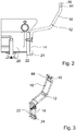
- Die
Figuren 2 und 3 zeigen die Halterungen ausFigur 1 in einer detaillierteren Darstellung. - Die Halterungen haben jeweils ein erstes, zur Befestigung an einem Regal ausgebildetes Ende 14 und ein zweites, zum Halten der Rammschutzstange ausgebildetes Ende 16. Beide Enden 14, 16 sind im montierten Zustand vertikal ausgerichtet und sind durch einen Verbindungsbereich 18 verbunden, der teilweise schräg verläuft und bewirkt, dass der Rammschutz vor dem Regal in der gewünschten Höhe gehalten wird, wenn die Rammschutzvorrichtung montiert ist. Die Halterung 12 ist in einer vorteilhaften Ausgestaltung aus einer Metallstange bzw. einem Metallband mit einem flachen, rechteckigen Querschnitt ausgebildet und so geformt und dimensioniert, dass Stöße von der erwarteten Kraft gegen die Rammschutzstange nicht zu einem Bruch führen sondern federnd abgefangen werden.
- Die Rammschutzvorrichtung kann je nach Regaltyp an einem Fußteil bzw. Regalsockel 20, einer Säule, einer Konsole oder auch an einem Regalboden befestigt sein. In einer vorteilhaften Ausgestaltung des erfindungsgemäßen Regals bzw. eines Regalsystems umfasst das Regal dort, wo die Halterung 12 befestigt werden soll, eine angeschweißte Platte 22 mit einer Gewindebohrung zum Verschrauben der Halterung. Die Breite und Höhe der Platte 22 entspricht zumindest im Wesentlichen der Breite und Höhe des ersten Bereichs der Halterung 12, die mit der flachen, breiteren Seite des Querschnitts über ein Zwischenblech 24 an der Platte 22 anliegt und mit dieser verschraubt ist. Eine Verkleidung 26 (
Fig. 9 ) des Regalsockels 20 hat, sofern vorhanden, einen Durchbruch, durch welchen die Halterung 12 nach außen ragen kann. -
Fig. 4 zeigt die Rammschutzstange 10 in einem vormontierten Zustand. - Die Rammschutzstange 10 umfasst parallel zur Längsrichtung verlaufende Schlitze 28, in welche die Enden 16 der Halterungen 12 einsteckbar sind. Die Rammschutzstange 10 ist dadurch in einer quer zur Längsrichtung der Rammschutzstange 10 verlaufenden Aufsteckrichtung 30 (
Fig. 9 ) auf die zweiten Enden 16 der Halterungen 12 aufsteckbar, wie dies inFig. 9 erkennbar ist. - Die Rammschutzstange 10 umfasst ein Metallrohr 30 und zwei teilweise in ein Ende des Metallrohrs 30 eingesteckte Kunststoffteile 32a, die in dem in
Fig. 1 dargestellten Ausführungsbeispiel als Endkappen zum Verschließen eines offenen Endes des Metallrohrs 30 ausgebildet sind und die gleichzeitig der Befestigung der Rammschutzstange 10 an jeweils einer der Halterungen 12 dienen. - Die Kunststoffteile 32a sind in
Figuren 6 und 7 detaillierter dargestellt. Jedes Kunststoffteil 32a hat einen ersten, mit Sägezahnprofil ausgestatteten Bereich 34 zum Einstecken in das Metallrohr und einen Kragenbereich 36. Ein Außendurchmesser des Kunststoffteils 32a im Kragenbereich 36 ist gleich einem Außendurchmesser des Metallrohrs 30, so dass die Außenfläche des Kragenbereichs 36 die Außenfläche des Metallrohrs 30 stetig fortsetzt. - In die beiden Enden des aus Edelstahl gefertigten Metallrohrs 30, das in
Fig. 5 einzeln dargestellt ist, ist jeweils ein zum Ende des Rohrs hin offener Teilschlitz 38 eingearbeitet und das Kunststoffteil 32a hat ebenfalls eine Öffnung 40, die in der Längsrichtung bzw. in der Einsteckrichtung des Kunststoffteils 32a in das Metallrohr 30 sowohl mit dem profilierten Bereich 34 als auch mit dem Kragenbereich 36 des Kunststoffteils 32a überlappt. - Zur Montage der Rammschutzstange 10 werden zwei als Endkappen ausgebildete Kunststoffteile 32a in die beiden offenen Enden des Metallrohrs 10 eingesteckt, bis der Kragenbereich 36 an der Endkante des Metallrohrs 30 anschlägt. Ist das Kunststoffteil 32a bis zum Anschlag in das Metallrohr 30 eingesteckt, ergänzt sich der Teilschlitz 38 des Metallrohrs 30 mit der Öffnung 40 des Kunststoffteils 32a zu dem Schlitz 28 der Rammschutzstange 10.
- Das Kunststoffteil 32a hat einen radial über den mit Sägezahnprofil ausgestatteten Bereich 34 ragenden Vorsprung 42, der mit dem Teilschlitz 38 des Metallrohrs 30 in Eingriff steht und das Kunststoffteil gegen Verdrehen im Metallrohr 30 sichert. Aufgrund des Vorsprungs 42 kann das Kunststoffteil 32a in nur einer Drehlage in das Ende des Metallrohrs 30 eingesteckt werden, und der Vorsprung 42 gewährleistet, dass die Öffnung 40 des Kunststoffteils 32a unterhalb des Teilschlitzes 38 bzw. mit diesem fluchtend angeordnet ist. Um die Aufnahme des Vorsprungs 42 zu ermöglichen, ist die axiale Länge des Teilschlitzes 38 etwas größer als die Läge der Öffnung 40 im Kunststoffteil 32a im vollständig eingesteckten Zustand des Kunststoffteils 32a.
- Wie in
Fig. 2, 3 und9 dargestellt hat das zweite, freie Ende der mit dem Kunststoffteil 32a verbundenen Halterung 12 einen Durchbruch 44, in welchen eine an einer Innenwand der Öffnung 40 des Kunststoffteils 32a ausgebildete Rastnase 46 eingreift. Der Durchbruch 44 und die Rastnase 46 bilden Rastverbindungsmittel zum Befestigen der Rammschutzstange 10 an den Halterungen 12. - Zur Montage der Rammschutzvorrichtung werden zunächst die Halterungen 12 mit dem Regalsockel 20 verschraubt und die aus Metallrohr 30 und Kunststoffteilen 32a vormontierte Rammschutzstange 10 wird dann, wie dies in
Fig. 9 dargestellt ist, mit nach unten offenen Schlitzen 28 vertikal von oben auf die Halterungen 12 aufgesteckt, so dass die zweiten Enden 16 der Halterungen 12 in die Schlitze 28 gleiten bis die Rastverbindungsmittel 44, 46 einrasten. Zum Lösen der Rastverbindungsmittel 44, 46 können an den Stirnseiten der Kunststoffteile 32a oder an einer anderen geeigneten Stelle Öffnungen zum Einschieben von geeigneten Werkzeugen vorgesehen sein. - Die
Figur 8 zeigt ein zusätzliches, optionales Bauteil eines weiteren Ausführungsbeispiels der Erfindung. Um Wiederholungen zu vermeiden, beschränkt sich die nachfolgende Beschreibung dieses weiteren Ausführungsbeispiels im Wesentlichen auf Unterschiede zu dem ersten Ausführungsbeispiel der Erfindung. Wegen der unveränderten Merkmale wird auf die Beschreibung zum ersten Ausführungsbeispiel verwiesen. Für gleich oder ähnlich wirkende Merkmale der weiteren Merkmale werden gleiche Bezugszeichen verwendet, um die Ähnlichkeiten zu betonen. - Die Rammschutzvorrichtung nach dem zweiten Ausführungsbeispiel umfasst mehrere Metallrohre 30 der in
Fig. 5 dargestellten Art, die aber nicht jeweils zwei als Endkappen ausgebildete Kunststoffteile 32a umfassen sondern über ein als Verbinderelement ausgestaltetes Kunststoffelement 32b gemäßFig. 8 fluchtend miteinander verbunden sind und als gemeinsame Rammschutzstange für mehrere Regalmodule eines Regalsystems benutzt werden können. Nur die jeweils äußersten Enden der in der Reihe angeordneten Metallrohre 30 sind dann mit als Endkappen ausgestalteten Kunststoffteilen 32a der inFig. 6 und 7 dargestellten Art ausgestattet. - Das Kunststoffteil 32b hat keinen Kragenbereich, so dass die Metallstangen 30 auf Stoß miteinander verbunden werden können.
-
- 10
- Rammschutzstange
- 12
- Halterung
- 14
- erstes Ende
- 16
- zweites Ende
- 18
- Verbindungsbereich
- 20
- Regalsockel
- 22
- Platte
- 24
- Zwischenblech
- 26
- Verkleidung
- 28
- Schlitz
- 30
- Metallrohr
- 32a
- Kunststoffteile (Endkappe)
- 32b
- Kunststoffteil (Verbinder)
- 34
- Bereich
- 36
- Kragenbereich
- 38
- Teilschlitz
- 40
- Öffnung
- 42
- Vorsprung
- 44
- Durchbruch
- 46
- Rastnase
Claims (11)
- Rammschutzvorrichtung für ein Regal, umfassend eine Rammschutzstange (10) und wenigstens zwei Halterungen (12), wobei die Halterungen (12) ein freies, zum Halten der Rammschutzstange (10) ausgebildetes Ende (16) haben,
wobei die Rammschutzstange (10) in einer quer zur Längsrichtung der Rammschutzstange (10) verlaufenden Aufsteckrichtung (30) auf die freien Enden (16) der Halterungen (12) aufsteckbar ist,
wobei die Rammschutzstange (10) wenigstens ein Metallrohr (30) und zumindest ein wenigstens teilweise in ein Ende des Metallrohrs (30) eingestecktes Kunststoffteil (32a, 32b) umfasst, wobei das Kunststoffteil (32a, 32b) einer Befestigung der Rammschutzstange (10) an einer der Halterungen (12) dient, dadurch gekennzeichnet, dass das Ende des Metallrohrs (30) einen Teilschlitz (38) umfasst, der sich mit einer Öffnung (40)des Kunststoffteils (32a, 32b) zu dem Schlitz (28) der Rammschutzstange (10) ergänzt. - Rammschutzvorrichtung nach Anspruch 1,
gekennzeichnet durch Rastverbindungsmittel (44, 46) zum Befestigen der Rammschutzstange (10) an den Halterungen (12). - Rammschutzvorrichtung nach einem der vorhergehenden Ansprüche,
dadurch gekennzeichnet, dass
die Rammschutzstange (10) parallel zur Aufsteckrichtung (30) verlaufende Schlitze (28) umfasst, in welche die Enden (16) der Halterungen (12) einsteckbar sind. - Rammschutzvorrichtung nach Anspruch 1,
dadurch gekennzeichnet, dass
das Kunststoffteil (32a, 32b) einen Vorsprung (42) umfasst, der mit dem Teilschlitz (38) des Metallrohrs (30) in Eingriff steht und das Kunststoffteil (32a, 32b) gegen Verdrehen im Metallrohr (30) sichert. - Rammschutzvorrichtung nach einem der vorhergehenden Ansprüche,
dadurch gekennzeichnet, dass
das Kunststoffteil (32a) einen ersten, mit Sägezahnprofil ausgestatteten Bereich (34) zum Einstecken in das Metallrohr (30) und einen Kragenbereich (36) umfasst, wobei ein Außendurchmesser des Kunststoffteils (32a) im Kragenbereich (36) größer als ein Innendurchmesser des Metallrohrs (30) ist, insbesondere gleich einem Außendurchmesser des Metallrohrs (30) ist. - Rammschutzvorrichtung nach einem der vorhergehenden Ansprüche,
dadurch gekennzeichnet, dass
das Metallrohr (30) aus Edelstahl gefertigt ist. - Rammschutzvorrichtung nach einem der vorhergehenden Ansprüche,
dadurch gekennzeichnet, dass
das freie Ende (16) der mit dem Kunststoffteil (32a, 32b) verbundenen Halterung (12) eine Vertiefung oder einen Durchbruch (44) aufweist, in welche oder welchen eine an einer Innenwand der Öffnung (40) des Kunststoffteils (32a, 32b) ausgebildete Rastnase (46) eingreift. - Rammschutzvorrichtung nach einem der vorhergehenden Ansprüche,
dadurch gekennzeichnet, dass
das das Kunststoffteil (32b) als Verbinderelement zum fluchtenden Verbinden zweier Metallrohre (30) ausgebildet ist. - Rammschutzvorrichtung nach einem der vorhergehenden Ansprüche,
dadurch gekennzeichnet, dass
das das Kunststoffteil (32a) als Endkappe zum Verschließen eines offenen Endes des Metallrohrs (30) ausgebildet ist - Regal mit einer Rammschutzvorrichtung nach einem der vorhergehenden Ansprüche.
- Regal nach Anspruch 10,
dadurch gekennzeichnet, dass
die Halterungen (12) mit einem Regalsockel (20) des Regals verschraubt sind.
Priority Applications (3)
| Application Number | Priority Date | Filing Date | Title |
|---|---|---|---|
| RS20200182A RS59932B1 (sr) | 2017-03-03 | 2018-03-02 | Sklop odbojnika za police |
| PL18159830T PL3369343T3 (pl) | 2017-03-03 | 2018-03-02 | Urządzenie chroniące przed uderzeniem dla regału |
| SI201830033T SI3369343T1 (sl) | 2017-03-03 | 2018-03-02 | Naprava za zaščito pred udarci za regale |
Applications Claiming Priority (1)
| Application Number | Priority Date | Filing Date | Title |
|---|---|---|---|
| DE202017001171.9U DE202017001171U1 (de) | 2017-03-03 | 2017-03-03 | Rammschutzvorrichtung |
Publications (2)
| Publication Number | Publication Date |
|---|---|
| EP3369343A1 EP3369343A1 (de) | 2018-09-05 |
| EP3369343B1 true EP3369343B1 (de) | 2019-12-25 |
Family
ID=62636847
Family Applications (1)
| Application Number | Title | Priority Date | Filing Date |
|---|---|---|---|
| EP18159830.1A Active EP3369343B1 (de) | 2017-03-03 | 2018-03-02 | Rammschutzvorrichtung für regale |
Country Status (7)
| Country | Link |
|---|---|
| EP (1) | EP3369343B1 (de) |
| DE (1) | DE202017001171U1 (de) |
| DK (1) | DK3369343T3 (de) |
| ES (1) | ES2774753T3 (de) |
| PL (1) | PL3369343T3 (de) |
| RS (1) | RS59932B1 (de) |
| SI (1) | SI3369343T1 (de) |
Family Cites Families (10)
| Publication number | Priority date | Publication date | Assignee | Title |
|---|---|---|---|---|
| US3239070A (en) * | 1964-08-24 | 1966-03-08 | Garcy Corp | Hang rod assembly |
| JPS5145813U (de) * | 1974-10-02 | 1976-04-05 | ||
| US5033244A (en) * | 1989-07-21 | 1991-07-23 | Boston Metal Products Corp. | Corner assembly for flush fitting protective strip assembly |
| DE9202215U1 (de) * | 1992-02-20 | 1992-10-22 | Eickmeier, Ursula, 4971 Hüllhorst | Regalsystem |
| FR2750588B1 (fr) * | 1996-07-04 | 1998-09-18 | Mapal Sa | Barriere basse de protection anti-choc pour meubles de vente et applications analogues |
| DE20211963U1 (de) * | 2002-08-03 | 2003-02-20 | WELITA Wärme- Elektro- und lichttechnische Anlagen GmbH, 23816 Bebensee | Stauchbefestigungstechnik |
| ATE471287T1 (de) * | 2003-11-18 | 2010-07-15 | Innovation Central Pty Ltd | Elastische schutzvorrichtung zum schützen einer struktur vor aufprall |
| DE202012102741U1 (de) | 2012-07-20 | 2013-10-22 | Tegometall International Ag | Rückwandprofil für ein modulares Regalsystem |
| DE202014000325U1 (de) * | 2014-01-17 | 2015-05-06 | Kesseböhmer Holding e.K. | Vorrichtung zur Präsentation und Ausgabe von Waren, insbesondere Backwaren |
| US9326605B2 (en) * | 2014-07-29 | 2016-05-03 | Hussmann Corporation | Bumper for a merchandiser |
-
2017
- 2017-03-03 DE DE202017001171.9U patent/DE202017001171U1/de not_active Expired - Lifetime
-
2018
- 2018-03-02 EP EP18159830.1A patent/EP3369343B1/de active Active
- 2018-03-02 DK DK18159830.1T patent/DK3369343T3/da active
- 2018-03-02 PL PL18159830T patent/PL3369343T3/pl unknown
- 2018-03-02 SI SI201830033T patent/SI3369343T1/sl unknown
- 2018-03-02 RS RS20200182A patent/RS59932B1/sr unknown
- 2018-03-02 ES ES18159830T patent/ES2774753T3/es active Active
Non-Patent Citations (1)
| Title |
|---|
| None * |
Also Published As
| Publication number | Publication date |
|---|---|
| DK3369343T3 (da) | 2020-03-02 |
| DE202017001171U1 (de) | 2018-06-06 |
| EP3369343A1 (de) | 2018-09-05 |
| SI3369343T1 (sl) | 2020-04-30 |
| ES2774753T3 (es) | 2020-07-22 |
| RS59932B1 (sr) | 2020-03-31 |
| PL3369343T3 (pl) | 2020-07-27 |
Similar Documents
| Publication | Publication Date | Title |
|---|---|---|
| EP1228925B1 (de) | Befestigungsvorrichtung für Heckleuchten von Fahrzeugen, vorzugsweise von Kraftfahrzeugen | |
| EP2612406B1 (de) | Rahmenschenkel für ein gestell | |
| DE102005021663B3 (de) | Crashbox | |
| EP3374648B1 (de) | Verbindungsbaugruppe für montageschienen | |
| EP3569108B1 (de) | Regalsystem zum einbau in ein fahrzeug | |
| WO2016012081A1 (de) | Befestiger für eine montageschiene | |
| DE29917714U1 (de) | Außenrückblickspiegel für Fahrzeuge, insbesondere Kraftfahrzeuge | |
| EP2628411A2 (de) | Auszug | |
| DE102013006723A1 (de) | Hohlprofilträger für eine Tragvorrichtung zum Tragen von Werkzeugen, Werkstücken oder dergleichen, System zum Aufbauen einer derartigen Tragvorrichtung sowie Kreuzverbinder und Vorrichtung zur Befestigung eines Endeffektors an einem Grundrahmen an einer derartigen Tragvorrichtung | |
| DE10225403B4 (de) | Ständerwerk | |
| DE202016101843U1 (de) | Sperrbalken | |
| DE102016115862A1 (de) | Schutzvorrichtung für einen Regalpfosten | |
| EP3369343A1 (de) | Rammschutzvorrichtung für regale | |
| DE202005010186U1 (de) | Halteeinrichtung sowie Halteelement hierfür | |
| DE102021115852B4 (de) | Montageanordnung für den Innenausbau eines Schaltschrankgehäuses | |
| DE102020116401A1 (de) | Bolzenaufnahme und Bolzenbefestigungssystem | |
| EP4080069B1 (de) | System zur befestigung | |
| EP3964369B1 (de) | Montagesystem | |
| DE202018106096U1 (de) | Plattenhalter und Plattenhalter-Bausatz | |
| EP3828426B1 (de) | Verbindungselement für mehrkantrohre | |
| DE102012108688A1 (de) | Säulenprofileinrichtung und Bodenprofil zum Einbau in einem Fahrzeug sowie Regalsystem hierzu | |
| EP1661491B1 (de) | Tragrahmen | |
| EP3727091B1 (de) | Anordnung aus wenigstens einer relingstange und wenigstens einem wandelement einer schublade | |
| EP1134170A1 (de) | Modulartig zusammensetzbare Struktur für Lagerregale | |
| EP3044534B1 (de) | Montagesystem zur befestigung eines anbauteiles an einer c-schiene |
Legal Events
| Date | Code | Title | Description |
|---|---|---|---|
| PUAI | Public reference made under article 153(3) epc to a published international application that has entered the european phase |
Free format text: ORIGINAL CODE: 0009012 |
|
| STAA | Information on the status of an ep patent application or granted ep patent |
Free format text: STATUS: THE APPLICATION HAS BEEN PUBLISHED |
|
| AK | Designated contracting states |
Kind code of ref document: A1 Designated state(s): AL AT BE BG CH CY CZ DE DK EE ES FI FR GB GR HR HU IE IS IT LI LT LU LV MC MK MT NL NO PL PT RO RS SE SI SK SM TR |
|
| AX | Request for extension of the european patent |
Extension state: BA ME |
|
| STAA | Information on the status of an ep patent application or granted ep patent |
Free format text: STATUS: REQUEST FOR EXAMINATION WAS MADE |
|
| 17P | Request for examination filed |
Effective date: 20190305 |
|
| RBV | Designated contracting states (corrected) |
Designated state(s): AL AT BE BG CH CY CZ DE DK EE ES FI FR GB GR HR HU IE IS IT LI LT LU LV MC MK MT NL NO PL PT RO RS SE SI SK SM TR |
|
| GRAP | Despatch of communication of intention to grant a patent |
Free format text: ORIGINAL CODE: EPIDOSNIGR1 |
|
| STAA | Information on the status of an ep patent application or granted ep patent |
Free format text: STATUS: GRANT OF PATENT IS INTENDED |
|
| RIC1 | Information provided on ipc code assigned before grant |
Ipc: A47B 95/04 20060101AFI20190607BHEP |
|
| INTG | Intention to grant announced |
Effective date: 20190711 |
|
| GRAS | Grant fee paid |
Free format text: ORIGINAL CODE: EPIDOSNIGR3 |
|
| GRAA | (expected) grant |
Free format text: ORIGINAL CODE: 0009210 |
|
| STAA | Information on the status of an ep patent application or granted ep patent |
Free format text: STATUS: THE PATENT HAS BEEN GRANTED |
|
| AK | Designated contracting states |
Kind code of ref document: B1 Designated state(s): AL AT BE BG CH CY CZ DE DK EE ES FI FR GB GR HR HU IE IS IT LI LT LU LV MC MK MT NL NO PL PT RO RS SE SI SK SM TR |
|
| REG | Reference to a national code |
Ref country code: GB Ref legal event code: FG4D Free format text: NOT ENGLISH |
|
| REG | Reference to a national code |
Ref country code: CH Ref legal event code: EP |
|
| REG | Reference to a national code |
Ref country code: AT Ref legal event code: REF Ref document number: 1216170 Country of ref document: AT Kind code of ref document: T Effective date: 20200115 |
|
| REG | Reference to a national code |
Ref country code: DE Ref legal event code: R096 Ref document number: 502018000543 Country of ref document: DE |
|
| REG | Reference to a national code |
Ref country code: IE Ref legal event code: FG4D Free format text: LANGUAGE OF EP DOCUMENT: GERMAN |
|
| REG | Reference to a national code |
Ref country code: RO Ref legal event code: EPE |
|
| REG | Reference to a national code |
Ref country code: DK Ref legal event code: T3 Effective date: 20200227 |
|
| REG | Reference to a national code |
Ref country code: SE Ref legal event code: TRGR |
|
| REG | Reference to a national code |
Ref country code: NL Ref legal event code: FP |
|
| REG | Reference to a national code |
Ref country code: NO Ref legal event code: T2 Effective date: 20191225 |
|
| PG25 | Lapsed in a contracting state [announced via postgrant information from national office to epo] |
Ref country code: LV Free format text: LAPSE BECAUSE OF FAILURE TO SUBMIT A TRANSLATION OF THE DESCRIPTION OR TO PAY THE FEE WITHIN THE PRESCRIBED TIME-LIMIT Effective date: 20191225 Ref country code: BG Free format text: LAPSE BECAUSE OF FAILURE TO SUBMIT A TRANSLATION OF THE DESCRIPTION OR TO PAY THE FEE WITHIN THE PRESCRIBED TIME-LIMIT Effective date: 20200325 Ref country code: FI Free format text: LAPSE BECAUSE OF FAILURE TO SUBMIT A TRANSLATION OF THE DESCRIPTION OR TO PAY THE FEE WITHIN THE PRESCRIBED TIME-LIMIT Effective date: 20191225 Ref country code: LT Free format text: LAPSE BECAUSE OF FAILURE TO SUBMIT A TRANSLATION OF THE DESCRIPTION OR TO PAY THE FEE WITHIN THE PRESCRIBED TIME-LIMIT Effective date: 20191225 |
|
| REG | Reference to a national code |
Ref country code: LT Ref legal event code: MG4D |
|
| REG | Reference to a national code |
Ref country code: GR Ref legal event code: EP Ref document number: 20200400445 Country of ref document: GR Effective date: 20200511 |
|
| PG25 | Lapsed in a contracting state [announced via postgrant information from national office to epo] |
Ref country code: HR Free format text: LAPSE BECAUSE OF FAILURE TO SUBMIT A TRANSLATION OF THE DESCRIPTION OR TO PAY THE FEE WITHIN THE PRESCRIBED TIME-LIMIT Effective date: 20191225 |
|
| REG | Reference to a national code |
Ref country code: SK Ref legal event code: T3 Ref document number: E 33600 Country of ref document: SK |
|
| PG25 | Lapsed in a contracting state [announced via postgrant information from national office to epo] |
Ref country code: AL Free format text: LAPSE BECAUSE OF FAILURE TO SUBMIT A TRANSLATION OF THE DESCRIPTION OR TO PAY THE FEE WITHIN THE PRESCRIBED TIME-LIMIT Effective date: 20191225 |
|
| REG | Reference to a national code |
Ref country code: ES Ref legal event code: FG2A Ref document number: 2774753 Country of ref document: ES Kind code of ref document: T3 Effective date: 20200722 |
|
| PG25 | Lapsed in a contracting state [announced via postgrant information from national office to epo] |
Ref country code: EE Free format text: LAPSE BECAUSE OF FAILURE TO SUBMIT A TRANSLATION OF THE DESCRIPTION OR TO PAY THE FEE WITHIN THE PRESCRIBED TIME-LIMIT Effective date: 20191225 Ref country code: PT Free format text: LAPSE BECAUSE OF FAILURE TO SUBMIT A TRANSLATION OF THE DESCRIPTION OR TO PAY THE FEE WITHIN THE PRESCRIBED TIME-LIMIT Effective date: 20200520 |
|
| PG25 | Lapsed in a contracting state [announced via postgrant information from national office to epo] |
Ref country code: SM Free format text: LAPSE BECAUSE OF FAILURE TO SUBMIT A TRANSLATION OF THE DESCRIPTION OR TO PAY THE FEE WITHIN THE PRESCRIBED TIME-LIMIT Effective date: 20191225 Ref country code: IS Free format text: LAPSE BECAUSE OF FAILURE TO SUBMIT A TRANSLATION OF THE DESCRIPTION OR TO PAY THE FEE WITHIN THE PRESCRIBED TIME-LIMIT Effective date: 20200425 |
|
| REG | Reference to a national code |
Ref country code: DE Ref legal event code: R097 Ref document number: 502018000543 Country of ref document: DE |
|
| PG25 | Lapsed in a contracting state [announced via postgrant information from national office to epo] |
Ref country code: MC Free format text: LAPSE BECAUSE OF FAILURE TO SUBMIT A TRANSLATION OF THE DESCRIPTION OR TO PAY THE FEE WITHIN THE PRESCRIBED TIME-LIMIT Effective date: 20191225 |
|
| PLBE | No opposition filed within time limit |
Free format text: ORIGINAL CODE: 0009261 |
|
| STAA | Information on the status of an ep patent application or granted ep patent |
Free format text: STATUS: NO OPPOSITION FILED WITHIN TIME LIMIT |
|
| 26N | No opposition filed |
Effective date: 20200928 |
|
| PG25 | Lapsed in a contracting state [announced via postgrant information from national office to epo] |
Ref country code: LU Free format text: LAPSE BECAUSE OF NON-PAYMENT OF DUE FEES Effective date: 20200302 |
|
| PGFP | Annual fee paid to national office [announced via postgrant information from national office to epo] |
Ref country code: NO Payment date: 20210318 Year of fee payment: 4 Ref country code: RO Payment date: 20210301 Year of fee payment: 4 |
|
| PGFP | Annual fee paid to national office [announced via postgrant information from national office to epo] |
Ref country code: RS Payment date: 20210301 Year of fee payment: 4 Ref country code: SE Payment date: 20210322 Year of fee payment: 4 Ref country code: BE Payment date: 20210326 Year of fee payment: 4 |
|
| PGFP | Annual fee paid to national office [announced via postgrant information from national office to epo] |
Ref country code: ES Payment date: 20210413 Year of fee payment: 4 |
|
| PG25 | Lapsed in a contracting state [announced via postgrant information from national office to epo] |
Ref country code: TR Free format text: LAPSE BECAUSE OF FAILURE TO SUBMIT A TRANSLATION OF THE DESCRIPTION OR TO PAY THE FEE WITHIN THE PRESCRIBED TIME-LIMIT Effective date: 20191225 Ref country code: MT Free format text: LAPSE BECAUSE OF FAILURE TO SUBMIT A TRANSLATION OF THE DESCRIPTION OR TO PAY THE FEE WITHIN THE PRESCRIBED TIME-LIMIT Effective date: 20191225 Ref country code: CY Free format text: LAPSE BECAUSE OF FAILURE TO SUBMIT A TRANSLATION OF THE DESCRIPTION OR TO PAY THE FEE WITHIN THE PRESCRIBED TIME-LIMIT Effective date: 20191225 |
|
| PG25 | Lapsed in a contracting state [announced via postgrant information from national office to epo] |
Ref country code: MK Free format text: LAPSE BECAUSE OF FAILURE TO SUBMIT A TRANSLATION OF THE DESCRIPTION OR TO PAY THE FEE WITHIN THE PRESCRIBED TIME-LIMIT Effective date: 20191225 |
|
| REG | Reference to a national code |
Ref country code: NO Ref legal event code: MMEP |
|
| PG25 | Lapsed in a contracting state [announced via postgrant information from national office to epo] |
Ref country code: RO Free format text: LAPSE BECAUSE OF NON-PAYMENT OF DUE FEES Effective date: 20220302 |
|
| PG25 | Lapsed in a contracting state [announced via postgrant information from national office to epo] |
Ref country code: RS Free format text: LAPSE BECAUSE OF NON-PAYMENT OF DUE FEES Effective date: 20220302 |
|
| REG | Reference to a national code |
Ref country code: BE Ref legal event code: MM Effective date: 20220331 |
|
| PG25 | Lapsed in a contracting state [announced via postgrant information from national office to epo] |
Ref country code: SE Free format text: LAPSE BECAUSE OF NON-PAYMENT OF DUE FEES Effective date: 20220303 Ref country code: NO Free format text: LAPSE BECAUSE OF NON-PAYMENT OF DUE FEES Effective date: 20220331 |
|
| PG25 | Lapsed in a contracting state [announced via postgrant information from national office to epo] |
Ref country code: BE Free format text: LAPSE BECAUSE OF NON-PAYMENT OF DUE FEES Effective date: 20220331 |
|
| REG | Reference to a national code |
Ref country code: ES Ref legal event code: FD2A Effective date: 20230427 |
|
| PG25 | Lapsed in a contracting state [announced via postgrant information from national office to epo] |
Ref country code: ES Free format text: LAPSE BECAUSE OF NON-PAYMENT OF DUE FEES Effective date: 20220303 |
|
| PGFP | Annual fee paid to national office [announced via postgrant information from national office to epo] |
Ref country code: CH Payment date: 20250401 Year of fee payment: 8 |
|
| REG | Reference to a national code |
Ref country code: CH Ref legal event code: U11 Free format text: ST27 STATUS EVENT CODE: U-0-0-U10-U11 (AS PROVIDED BY THE NATIONAL OFFICE) Effective date: 20260401 |
|
| PGFP | Annual fee paid to national office [announced via postgrant information from national office to epo] |
Ref country code: GB Payment date: 20260319 Year of fee payment: 9 |
|
| PGFP | Annual fee paid to national office [announced via postgrant information from national office to epo] |
Ref country code: DE Payment date: 20260324 Year of fee payment: 9 Ref country code: DK Payment date: 20260323 Year of fee payment: 9 Ref country code: IE Payment date: 20260324 Year of fee payment: 9 |
|
| PGFP | Annual fee paid to national office [announced via postgrant information from national office to epo] |
Ref country code: AT Payment date: 20260324 Year of fee payment: 9 |
|
| PGFP | Annual fee paid to national office [announced via postgrant information from national office to epo] |
Ref country code: IT Payment date: 20260320 Year of fee payment: 9 |
|
| PGFP | Annual fee paid to national office [announced via postgrant information from national office to epo] |
Ref country code: NL Payment date: 20260323 Year of fee payment: 9 |
|
| PGFP | Annual fee paid to national office [announced via postgrant information from national office to epo] |
Ref country code: FR Payment date: 20260323 Year of fee payment: 9 |
|
| PGFP | Annual fee paid to national office [announced via postgrant information from national office to epo] |
Ref country code: CZ Payment date: 20260216 Year of fee payment: 9 |
|
| PGFP | Annual fee paid to national office [announced via postgrant information from national office to epo] |
Ref country code: GR Payment date: 20260326 Year of fee payment: 9 Ref country code: PL Payment date: 20260209 Year of fee payment: 9 |
|
| PGFP | Annual fee paid to national office [announced via postgrant information from national office to epo] |
Ref country code: SK Payment date: 20260213 Year of fee payment: 9 |
|
| PGFP | Annual fee paid to national office [announced via postgrant information from national office to epo] |
Ref country code: SI Payment date: 20260210 Year of fee payment: 9 |