EP3367767A1 - Enceinte hôte de montage de paroi verticale - Google Patents
Enceinte hôte de montage de paroi verticale Download PDFInfo
- Publication number
- EP3367767A1 EP3367767A1 EP18158362.6A EP18158362A EP3367767A1 EP 3367767 A1 EP3367767 A1 EP 3367767A1 EP 18158362 A EP18158362 A EP 18158362A EP 3367767 A1 EP3367767 A1 EP 3367767A1
- Authority
- EP
- European Patent Office
- Prior art keywords
- mounting
- extensions
- backpan
- wall mount
- door
- Prior art date
- Legal status (The legal status is an assumption and is not a legal conclusion. Google has not performed a legal analysis and makes no representation as to the accuracy of the status listed.)
- Granted
Links
- 230000007246 mechanism Effects 0.000 description 3
- 230000008901 benefit Effects 0.000 description 2
- 230000003466 anti-cipated effect Effects 0.000 description 1
- 238000000576 coating method Methods 0.000 description 1
- 238000010348 incorporation Methods 0.000 description 1
- 239000003973 paint Substances 0.000 description 1
- 230000001737 promoting effect Effects 0.000 description 1
- 238000003466 welding Methods 0.000 description 1
Images


Classifications
-
- H—ELECTRICITY
- H02—GENERATION; CONVERSION OR DISTRIBUTION OF ELECTRIC POWER
- H02G—INSTALLATION OF ELECTRIC CABLES OR LINES, OR OF COMBINED OPTICAL AND ELECTRIC CABLES OR LINES
- H02G3/00—Installations of electric cables or lines or protective tubing therefor in or on buildings, equivalent structures or vehicles
- H02G3/02—Details
- H02G3/08—Distribution boxes; Connection or junction boxes
- H02G3/10—Distribution boxes; Connection or junction boxes for surface mounting on a wall
-
- H—ELECTRICITY
- H02—GENERATION; CONVERSION OR DISTRIBUTION OF ELECTRIC POWER
- H02B—BOARDS, SUBSTATIONS OR SWITCHING ARRANGEMENTS FOR THE SUPPLY OR DISTRIBUTION OF ELECTRIC POWER
- H02B1/00—Frameworks, boards, panels, desks, casings; Details of substations or switching arrangements
- H02B1/26—Casings; Parts thereof or accessories therefor
- H02B1/40—Wall-mounted casings; Parts thereof or accessories therefor
-
- H—ELECTRICITY
- H02—GENERATION; CONVERSION OR DISTRIBUTION OF ELECTRIC POWER
- H02G—INSTALLATION OF ELECTRIC CABLES OR LINES, OR OF COMBINED OPTICAL AND ELECTRIC CABLES OR LINES
- H02G3/00—Installations of electric cables or lines or protective tubing therefor in or on buildings, equivalent structures or vehicles
- H02G3/02—Details
- H02G3/08—Distribution boxes; Connection or junction boxes
- H02G3/081—Bases, casings or covers
-
- H—ELECTRICITY
- H05—ELECTRIC TECHNIQUES NOT OTHERWISE PROVIDED FOR
- H05K—PRINTED CIRCUITS; CASINGS OR CONSTRUCTIONAL DETAILS OF ELECTRIC APPARATUS; MANUFACTURE OF ASSEMBLAGES OF ELECTRICAL COMPONENTS
- H05K5/00—Casings, cabinets or drawers for electric apparatus
- H05K5/0004—Casings, cabinets or drawers for electric apparatus comprising several parts forming a closed casing
- H05K5/0008—Casings, cabinets or drawers for electric apparatus comprising several parts forming a closed casing assembled by screws
-
- H—ELECTRICITY
- H05—ELECTRIC TECHNIQUES NOT OTHERWISE PROVIDED FOR
- H05K—PRINTED CIRCUITS; CASINGS OR CONSTRUCTIONAL DETAILS OF ELECTRIC APPARATUS; MANUFACTURE OF ASSEMBLAGES OF ELECTRICAL COMPONENTS
- H05K5/00—Casings, cabinets or drawers for electric apparatus
- H05K5/02—Details
- H05K5/0217—Mechanical details of casings
- H05K5/0221—Locks; Latches
-
- H—ELECTRICITY
- H05—ELECTRIC TECHNIQUES NOT OTHERWISE PROVIDED FOR
- H05K—PRINTED CIRCUITS; CASINGS OR CONSTRUCTIONAL DETAILS OF ELECTRIC APPARATUS; MANUFACTURE OF ASSEMBLAGES OF ELECTRICAL COMPONENTS
- H05K7/00—Constructional details common to different types of electric apparatus
- H05K7/14—Mounting supporting structure in casing or on frame or rack
-
- H—ELECTRICITY
- H02—GENERATION; CONVERSION OR DISTRIBUTION OF ELECTRIC POWER
- H02B—BOARDS, SUBSTATIONS OR SWITCHING ARRANGEMENTS FOR THE SUPPLY OR DISTRIBUTION OF ELECTRIC POWER
- H02B1/00—Frameworks, boards, panels, desks, casings; Details of substations or switching arrangements
- H02B1/26—Casings; Parts thereof or accessories therefor
- H02B1/40—Wall-mounted casings; Parts thereof or accessories therefor
- H02B1/44—Hinged covers or doors
-
- H—ELECTRICITY
- H02—GENERATION; CONVERSION OR DISTRIBUTION OF ELECTRIC POWER
- H02G—INSTALLATION OF ELECTRIC CABLES OR LINES, OR OF COMBINED OPTICAL AND ELECTRIC CABLES OR LINES
- H02G3/00—Installations of electric cables or lines or protective tubing therefor in or on buildings, equivalent structures or vehicles
- H02G3/02—Details
- H02G3/08—Distribution boxes; Connection or junction boxes
- H02G3/086—Assembled boxes
Definitions
- the application relates to a wall mount enclosure, especially but not exclusively for electrical and electronic equipment.
- Wall-mountable cabinets for housing electrical and electronic equipment are known. Examples are shown in commonly assigned US Patent No. 7,188,570 . However, there is still room for improvement.
- the present invention relates to wall mount enclosures with removable side panels for permitting expansion of the enclosure depending on the needs of the user.
- the enclosure comprises a backpan with a back panel and a plurality of side panels extending forwards from the back panel, a plurality of extensions releasably attached to the backpan side panels and releasably attached to adjacent ones of the plurality of extensions to form an extension assembly extending forwards from the backpan, wherein the extension assembly as an assembly is releasable from and attachable to the backpan, and wherein individual extensions are releasable from and attachable to the backpan and their respective adjacent extensions, and at least one door removably attaches to one of the extensions and is movable between a closed position in which the door obstructs access to at least part of an opening defined by front edges of the extensions and an open position in which the door does not obstruct access to an interior of the enclosure.
- At least one of the doors may then be provided with a lock to secure the door in its closed position.
- At least one door may have a base panel that is removably secured to at least one of the extensions and an access door that is rotatably attached to the base panel.
- the backpan may have at least one support bracket with an array of mounting apertures.
- the extensions may be devoid of any provision for mounting of equipment, requiring that all equipment be mounted directly to the backpan or on supports that are mounted to the backpan without involving the extensions, except that light equipment may also be mounted on the inside of the door.
- At least one mounting bracket that comprises a bracket flange comprising at least one shovel lance with a joggled leg dimensioned to fit into a mounting aperture in the support bracket with the bracket flange abutting the support bracket, a mounting plate extending forward from the bracket flange and provided with a plurality of apertures permitting attachment of devices in vertical, horizontal, and diagonal orientations.
- the bracket flange may be provided with at least two said shovel lances, spaced at a distance equal to a spacing of the corresponding mounting apertures or an integer multiple of the spacing of the corresponding mounting apertures.
- the plurality of apertures in the mounting plate of the mounting bracket may comprise diagonally extending slots.
- the mounting bracket may further comprise at least one flange extending from an edge of the mounting plate and provided with additional mounting apertures.
- first and second mounting brackets mounted level with each another on opposite sides of the backpan, and at least one mounting rail may then extend between and be attached to both of the first and second mounting brackets.
- a kit of parts for a wall mount enclosure may comprise the backpan, a set of extensions, and at least one door.
- the kit of parts may further comprise a second set of extensions with a different size in a direction towards and away from the backpan.
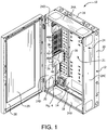
- the enclosure 10 includes a backpan 12 with a back panel 14 which is configured to mount to a supporting wall.
- the mounting to the wall can be through any conventional means such as bolts.
- bolts are appropriately attached to the wall and have a head that protrudes and is received in a slot (not shown) in the back panel 14.
- the bolt/slot attachment permits the backpan 12 to be removably attached to the wall.
- the back pan 10 includes a top panel 16 and a bottom panel 18 that are preferably formed integral with a top edge and bottom edge, respectively, of the back panel 14.
- the top and bottom panels 16, 18 protrude away from the back panel 14 and the wall.
- the top and bottom panels 16, 18 are relatively short in depth compared to the width of the back panel 14 so as to protrude outward a distance of about three (3) inches.
- the backpan 12 also includes two side panels 20 that are preferably formed integral with opposite sides edges of the back panel 14. To provide additional stiffness, the side panels 20 are preferably attached to edges of the top and bottom panels 16, 18.
- the attachment is preferably through a fixed, non-removable attachment, such as welding, although it is also contemplated that the attachment could be removable, such as with screws or bolts. While the panels are integral in the preferred embodiment, it is also contemplated that they could be separate panels that are attached to one another.
- the combination of the top, bottom and side panels 16, 18, 20 and back panel 14 form the backpan 12 with an interior cavity 21 that has a shallow depth. As will be described in more detail below, the interior cavity 21 is intended to contain electrical equipment.
- the top, bottom and side panels each have a backpan flange 22 onto which are removably mounted one or more extensions 24.
- Each extension 24 is removably attached to a respective flange 22.
- the removable attachment is through screws or bolts that attach a mounting flange 26 on each extension 24 to the backpan flange 22.
- each mounting flange 26 preferably has a keyhole 23 through which a screw 25 is used to secure the extension 24 to the backpan 12.
- edges of the top extension 24A is removably secured to respective edges of the side extensions 24C and 24D.
- edges of the bottom extension 24B are secured to the edges of the side extensions 24C and 24D.
- the securing of the extensions to one another is through screws or bolts.
- the extensions 24 are configured, when attached to the backpan 12, to extend the depth of the enclosure 10 and provide a larger interior cavity 21.
- a bonding screw 27 is preferably used to provide electrical continuity between the two components.
- the screw 27 is a flat head undercut (countersink) with teeth formed on the sloped surfaces of the head that are configured to scrape away paint or other surface coatings as the screw is tightened in order to provide a good conductive connection.
- a bolt could be used, such as the one disclosed in US Patent No. 8,070,404 , the disclosure of which is incorporated herein by reference in its entirety.
- FIG. 3 illustrates the enclosure 10 where the extensions 24 are removed and the door 28 secured directly onto the backpan 12. This configuration of the invention is particularly useful if only small electronics are mounted within the interior cavity 21.
- the mountings for equipment are on the backpan, and not on the wall extensions 24. Therefore, the extensions can easily be replaced with extensions having a different width in the direction towards and away from the wall, to accommodate larger or smaller equipment, without needing to replace the entire enclosure, and indeed without disturbing equipment already mounted in the enclosure.
- the extensions 24 have a uniform depth.
- the extensions can have varying depths and sizes, permitting the enclosure 10 to have considerable versatility.
- a door 28 is attached to one of the extensions 24 so as to permit access to the interior 21.
- the door 28 is attached to one side extension 24D though hinges.
- the door 28 may include a transparent or translucent panel 29 for permitting viewing of the interior. It is contemplated that if the interior cavity does not need to be deep, the extensions 24 could be left off and the door could be attached to one of the one of the top, bottom or side panels 16, 18, 20.
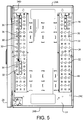
- the support brackets 30 include multiple mounting slots 32 and mounting apertures 34, preferably arranged in a series of alternating rows. In the illustrated embodiment of FIG. 5 , there are preferably three slots on each row. The incorporation of multiple slots in each row and multiple rows provides various mounting locations for attaching brackets and equipment, allowing the installer to choose the optimum location and facilitate cable management.
- the support brackets 30 are rigidly attached to the back panel 14 so as to provide a fixed mounting surface that is secured to the enclosure 10.
- mounting brackets 36 can be mounted to each support bracket 30 so as to extend outward from the backpan 12. Cross members (not shown) that are conventional in the art could be attached between the mounting brackets to permit mounting equipment vertically as opposed to horizontally. This permits the efficient use of space in the enclosure.
- FIGS. 6A-6B illustrate one configuration for a mounting bracket 36 for removably attaching to the support bracket 30.
- the mounting bracket 36 includes a bracket flange 38 and a mounting plate 40.
- the bracket flange includes at least one, and more preferably two or more, shovel lances 42 that include joggled legs spaced apart from the mounting flange 38.
- the legs of the shovel lances 42 are sized to fit into the slots 32 in the support bracket 30.
- the spacing of the shovel lances 42 is such that each of the shovel lances 42 is positioned to mate with a corresponding slot 32 in the support bracket 30.
- a bonding screw such as the one described above, is preferably used to provide electrical continuity between the two components.
- the mounting plate 40 includes multiple spaced apart apertures 46 for mounting electrical equipment in various orientations.
- FIG. 1 illustrates two different aperture arrangements that can be used for mounting plates 40A and 40B.
- apertures 46 there are a plurality of spaced apart holes 46A arranged in two or more rows and columns, and four diagonal slots 46B.
- the diagonal slots 46B are arranged so as to form an X shape.
- the unique layout of the apertures 46 in the mounting plate 40A permits multiple mounting configurations. For example, as shown in FIGS. 7A-7C , the aperture arrangement in mounting plate 40A permits six vertical mounting positions (vertical positions A-F in FIG. 7A ), four horizontal mounting positions (horizontal positions A-D in FIG. 7B ), and two diagonal mounting positions (diagonal positions A-B in FIG. 7C ). As shown in mounting plate 40B of FIG. 1 , the layout of the apertures 46 on the mounting plates 40 can vary depending on the anticipated needs of the user.
- the support plate 30 and mounting plates 36 preferably include additional apertures that are in the shape of secondary slots 48 sized for use with a Lever Lock® locking mechanism for removably securing brackets to the support plate 30 and mounting plates 36.
- the Lever Lock® locking mechanism is sold by Middle Atlantic Products, Inc. and is described in US Patent 9131622 , the disclosure of which is incorporated herein by reference in its entirety.
- the door brackets 50 include a plurality of slots 52 sized for use with Lever Lock® locking mechanisms for removably securing additional brackets 54 to the door. This would be particularly useful for mounting small devices on the door, thereby freeing up space inside the enclosure cavity for larger items.
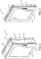
- FIGS. 9A and 9B illustrate an alternate embodiment of the extension panels and door in the enclosure 10.
- the side extensions 24C, 24D include a notched section 60 which is configured to permit mounting of a short door 62 that has a height less than the full height of the side extensions 24C, 24D.
- a secondary access door 64 that has a base panel 66 that is secured to the front edges 68 of the side extensions 24C, 24D.
- a hinge 70 connects the base panel 66 to an access door 72.
- a lock 74 may be included to restrict opening of the access door 72.
- FIGS. 9B The benefit of the configuration shown in FIGS. 9B is that once the electronics are mounted in the enclosure the use of two doors allows for limiting access to certain features and or components in the enclosure.
- the ability to incorporate a variety of extensions permits the enclosure to be arranged in a variety of different configurations, facilitating the efficient and useful mounting of electrical components, either vertically or horizontally.
Applications Claiming Priority (1)
| Application Number | Priority Date | Filing Date | Title |
|---|---|---|---|
| US201762464200P | 2017-02-27 | 2017-02-27 |
Publications (2)
| Publication Number | Publication Date |
|---|---|
| EP3367767A1 true EP3367767A1 (fr) | 2018-08-29 |
| EP3367767B1 EP3367767B1 (fr) | 2020-07-29 |
Family
ID=61283000
Family Applications (1)
| Application Number | Title | Priority Date | Filing Date |
|---|---|---|---|
| EP18158362.6A Active EP3367767B1 (fr) | 2017-02-27 | 2018-02-23 | Enceinte hôte de montage de paroi verticale |
Country Status (3)
| Country | Link |
|---|---|
| US (1) | US10250022B2 (fr) |
| EP (1) | EP3367767B1 (fr) |
| CA (1) | CA2996560C (fr) |
Families Citing this family (4)
| Publication number | Priority date | Publication date | Assignee | Title |
|---|---|---|---|---|
| US9926725B2 (en) * | 2015-01-22 | 2018-03-27 | Hubbell Incorporated | Lockable cover assembly |
| KR102082688B1 (ko) * | 2017-09-08 | 2020-04-23 | (주)토즈테크 | 부스바 일체형 계량기를 갖는 분전함 |
| US11362488B2 (en) * | 2018-12-05 | 2022-06-14 | Fuji Electric Fa Components & Systems Co., Ltd. | Panelboard device |
| CN113594915B (zh) * | 2021-10-08 | 2021-12-07 | 深圳市飞霞机电技术有限公司 | 一种机电工程控制柜用支撑框 |
Citations (7)
| Publication number | Priority date | Publication date | Assignee | Title |
|---|---|---|---|---|
| EP0454515A1 (fr) * | 1990-04-24 | 1991-10-30 | ROGER ELEKTRONIKBAUTEILE GmbH | Boîtier à compartiments multiples pour le logement de composants électriques ou électroniques |
| US7188570B2 (en) | 2005-03-08 | 2007-03-13 | Middle Atlantic Products, Inc. | Electrical equipment enclosure |
| DE102008058935B3 (de) * | 2008-11-25 | 2010-04-15 | Rittal Gmbh & Co. Kg | Gehäuse |
| US20100236298A1 (en) * | 2009-03-23 | 2010-09-23 | Diversified Control, Inc. | High-Security Enclosure |
| US8070404B1 (en) | 2008-11-06 | 2011-12-06 | Middle Atlantic Products, Inc. | Bonding fastener assembly for electrical grounding |
| US20140262491A1 (en) * | 2013-03-14 | 2014-09-18 | Asco Power Technologies, L.P. | Electrical Enclosure Expandable in the Z Direction |
| US9131622B2 (en) | 2011-06-03 | 2015-09-08 | Middle Atlantic Products, Inc. | Rack rail locking lever |
Family Cites Families (8)
| Publication number | Priority date | Publication date | Assignee | Title |
|---|---|---|---|---|
| US7109414B2 (en) * | 2004-11-12 | 2006-09-19 | Paul Reynolds | Electrical box straddling a construction stud |
| US20080264880A1 (en) | 2007-04-26 | 2008-10-30 | Wagner Tod A | Apparatus and Method for Housing Electronic Equipment and Increasing Floor Space Utilization |
| US8212144B1 (en) * | 2010-01-27 | 2012-07-03 | Arlington Industries, Inc. | Gangable modular electrical box assembly with interlocking modules |
| US9035175B2 (en) * | 2012-10-01 | 2015-05-19 | Hubbell Incorporated | Multi-gang adjustable electrical box |
| US8680407B1 (en) * | 2012-10-04 | 2014-03-25 | Vpl Enterprises Ltd. | Modular enclosure assembly for terminals wiring and distribution |
| US8987593B2 (en) * | 2013-02-28 | 2015-03-24 | Hubbell Incorporated | Electrical box extension assembly |
| JP6028932B2 (ja) * | 2013-10-11 | 2016-11-24 | 住友電装株式会社 | 電気接続箱 |
| JP6191093B2 (ja) * | 2014-07-23 | 2017-09-06 | 住友電装株式会社 | 電気接続箱 |
-
2018
- 2018-02-23 EP EP18158362.6A patent/EP3367767B1/fr active Active
- 2018-02-26 CA CA2996560A patent/CA2996560C/fr active Active
- 2018-02-26 US US15/905,073 patent/US10250022B2/en active Active
Patent Citations (7)
| Publication number | Priority date | Publication date | Assignee | Title |
|---|---|---|---|---|
| EP0454515A1 (fr) * | 1990-04-24 | 1991-10-30 | ROGER ELEKTRONIKBAUTEILE GmbH | Boîtier à compartiments multiples pour le logement de composants électriques ou électroniques |
| US7188570B2 (en) | 2005-03-08 | 2007-03-13 | Middle Atlantic Products, Inc. | Electrical equipment enclosure |
| US8070404B1 (en) | 2008-11-06 | 2011-12-06 | Middle Atlantic Products, Inc. | Bonding fastener assembly for electrical grounding |
| DE102008058935B3 (de) * | 2008-11-25 | 2010-04-15 | Rittal Gmbh & Co. Kg | Gehäuse |
| US20100236298A1 (en) * | 2009-03-23 | 2010-09-23 | Diversified Control, Inc. | High-Security Enclosure |
| US9131622B2 (en) | 2011-06-03 | 2015-09-08 | Middle Atlantic Products, Inc. | Rack rail locking lever |
| US20140262491A1 (en) * | 2013-03-14 | 2014-09-18 | Asco Power Technologies, L.P. | Electrical Enclosure Expandable in the Z Direction |
Also Published As
| Publication number | Publication date |
|---|---|
| US20180248347A1 (en) | 2018-08-30 |
| CA2996560C (fr) | 2023-07-25 |
| US10250022B2 (en) | 2019-04-02 |
| EP3367767B1 (fr) | 2020-07-29 |
| CA2996560A1 (fr) | 2018-08-27 |
Similar Documents
| Publication | Publication Date | Title |
|---|---|---|
| CA2996560C (fr) | Enceinte d'accueil murale verticale | |
| US10178784B2 (en) | Rail seal for electronic equipment enclosure | |
| RU2562797C2 (ru) | Система и способ установки устройств высотой, кратной 1u, без использования инструментов | |
| US5488543A (en) | Frame stand | |
| US20040183409A1 (en) | Electrical equipment enclosure | |
| US20080035810A1 (en) | Offset brackets for expanding electronic equipment cabinets | |
| US5333744A (en) | Modular equipment support system | |
| EP2429271A2 (fr) | Jointl pour enceinte d'équipement électronique | |
| US11129294B2 (en) | Modular rack assembly | |
| EP2274963A1 (fr) | Ensemble alimentation électrique pour bâti de serveur et procédé de montage d'alimentation électrique pour bâti de serveur | |
| US6814417B2 (en) | Switchgear cabinet | |
| CA2962518C (fr) | Tablette de support multipiece | |
| JPH057921B2 (fr) | ||
| GB2494139A (en) | Flat panel mounting apparatus having a bracket to receive another device | |
| AU733078B2 (en) | Wall-mounted installation housing | |
| GB2160765A (en) | Improvements relating to cabinets or cubicles, suitable for switchgear | |
| US6829138B2 (en) | Enclosure apparatus for electrical excitation equipment and other applications | |
| RU70602U1 (ru) | Рамный каркас для распределительного шкафа | |
| JP3183183B2 (ja) | スライド棚 | |
| CN210183681U (zh) | 一种高效散热交换机机柜 | |
| PL239176B1 (pl) | Obudowa komputera z osłoną zewnętrznego okablowania | |
| WO2020242395A1 (fr) | Système d'armoire intérieure modulaire | |
| WO2000044182A1 (fr) | Coffret de cablage et equipement associe | |
| JP2001046159A (ja) | 組立式棚における対面式テーブルの仕切り装置 | |
| RU76766U1 (ru) | Базовая секция командного пункта интегрированного информационно-управляющего комплекса |
Legal Events
| Date | Code | Title | Description |
|---|---|---|---|
| PUAI | Public reference made under article 153(3) epc to a published international application that has entered the european phase |
Free format text: ORIGINAL CODE: 0009012 |
|
| STAA | Information on the status of an ep patent application or granted ep patent |
Free format text: STATUS: THE APPLICATION HAS BEEN PUBLISHED |
|
| AK | Designated contracting states |
Kind code of ref document: A1 Designated state(s): AL AT BE BG CH CY CZ DE DK EE ES FI FR GB GR HR HU IE IS IT LI LT LU LV MC MK MT NL NO PL PT RO RS SE SI SK SM TR |
|
| AX | Request for extension of the european patent |
Extension state: BA ME |
|
| STAA | Information on the status of an ep patent application or granted ep patent |
Free format text: STATUS: REQUEST FOR EXAMINATION WAS MADE |
|
| 17P | Request for examination filed |
Effective date: 20190125 |
|
| RBV | Designated contracting states (corrected) |
Designated state(s): AL AT BE BG CH CY CZ DE DK EE ES FI FR GB GR HR HU IE IS IT LI LT LU LV MC MK MT NL NO PL PT RO RS SE SI SK SM TR |
|
| GRAP | Despatch of communication of intention to grant a patent |
Free format text: ORIGINAL CODE: EPIDOSNIGR1 |
|
| STAA | Information on the status of an ep patent application or granted ep patent |
Free format text: STATUS: GRANT OF PATENT IS INTENDED |
|
| INTG | Intention to grant announced |
Effective date: 20200409 |
|
| RAP1 | Party data changed (applicant data changed or rights of an application transferred) |
Owner name: LEGRAND AV INC. |
|
| GRAS | Grant fee paid |
Free format text: ORIGINAL CODE: EPIDOSNIGR3 |
|
| GRAA | (expected) grant |
Free format text: ORIGINAL CODE: 0009210 |
|
| STAA | Information on the status of an ep patent application or granted ep patent |
Free format text: STATUS: THE PATENT HAS BEEN GRANTED |
|
| AK | Designated contracting states |
Kind code of ref document: B1 Designated state(s): AL AT BE BG CH CY CZ DE DK EE ES FI FR GB GR HR HU IE IS IT LI LT LU LV MC MK MT NL NO PL PT RO RS SE SI SK SM TR |
|
| REG | Reference to a national code |
Ref country code: CH Ref legal event code: EP |
|
| REG | Reference to a national code |
Ref country code: AT Ref legal event code: REF Ref document number: 1297374 Country of ref document: AT Kind code of ref document: T Effective date: 20200815 |
|
| REG | Reference to a national code |
Ref country code: IE Ref legal event code: FG4D |
|
| REG | Reference to a national code |
Ref country code: DE Ref legal event code: R096 Ref document number: 602018006324 Country of ref document: DE |
|
| REG | Reference to a national code |
Ref country code: NL Ref legal event code: FP |
|
| REG | Reference to a national code |
Ref country code: LT Ref legal event code: MG4D |
|
| REG | Reference to a national code |
Ref country code: AT Ref legal event code: MK05 Ref document number: 1297374 Country of ref document: AT Kind code of ref document: T Effective date: 20200729 |
|
| PG25 | Lapsed in a contracting state [announced via postgrant information from national office to epo] |
Ref country code: BG Free format text: LAPSE BECAUSE OF FAILURE TO SUBMIT A TRANSLATION OF THE DESCRIPTION OR TO PAY THE FEE WITHIN THE PRESCRIBED TIME-LIMIT Effective date: 20201029 Ref country code: LT Free format text: LAPSE BECAUSE OF FAILURE TO SUBMIT A TRANSLATION OF THE DESCRIPTION OR TO PAY THE FEE WITHIN THE PRESCRIBED TIME-LIMIT Effective date: 20200729 Ref country code: AT Free format text: LAPSE BECAUSE OF FAILURE TO SUBMIT A TRANSLATION OF THE DESCRIPTION OR TO PAY THE FEE WITHIN THE PRESCRIBED TIME-LIMIT Effective date: 20200729 Ref country code: HR Free format text: LAPSE BECAUSE OF FAILURE TO SUBMIT A TRANSLATION OF THE DESCRIPTION OR TO PAY THE FEE WITHIN THE PRESCRIBED TIME-LIMIT Effective date: 20200729 Ref country code: FI Free format text: LAPSE BECAUSE OF FAILURE TO SUBMIT A TRANSLATION OF THE DESCRIPTION OR TO PAY THE FEE WITHIN THE PRESCRIBED TIME-LIMIT Effective date: 20200729 Ref country code: GR Free format text: LAPSE BECAUSE OF FAILURE TO SUBMIT A TRANSLATION OF THE DESCRIPTION OR TO PAY THE FEE WITHIN THE PRESCRIBED TIME-LIMIT Effective date: 20201030 Ref country code: SE Free format text: LAPSE BECAUSE OF FAILURE TO SUBMIT A TRANSLATION OF THE DESCRIPTION OR TO PAY THE FEE WITHIN THE PRESCRIBED TIME-LIMIT Effective date: 20200729 Ref country code: PT Free format text: LAPSE BECAUSE OF FAILURE TO SUBMIT A TRANSLATION OF THE DESCRIPTION OR TO PAY THE FEE WITHIN THE PRESCRIBED TIME-LIMIT Effective date: 20201130 Ref country code: NO Free format text: LAPSE BECAUSE OF FAILURE TO SUBMIT A TRANSLATION OF THE DESCRIPTION OR TO PAY THE FEE WITHIN THE PRESCRIBED TIME-LIMIT Effective date: 20201029 Ref country code: ES Free format text: LAPSE BECAUSE OF FAILURE TO SUBMIT A TRANSLATION OF THE DESCRIPTION OR TO PAY THE FEE WITHIN THE PRESCRIBED TIME-LIMIT Effective date: 20200729 |
|
| PG25 | Lapsed in a contracting state [announced via postgrant information from national office to epo] |
Ref country code: IS Free format text: LAPSE BECAUSE OF FAILURE TO SUBMIT A TRANSLATION OF THE DESCRIPTION OR TO PAY THE FEE WITHIN THE PRESCRIBED TIME-LIMIT Effective date: 20201129 Ref country code: RS Free format text: LAPSE BECAUSE OF FAILURE TO SUBMIT A TRANSLATION OF THE DESCRIPTION OR TO PAY THE FEE WITHIN THE PRESCRIBED TIME-LIMIT Effective date: 20200729 Ref country code: LV Free format text: LAPSE BECAUSE OF FAILURE TO SUBMIT A TRANSLATION OF THE DESCRIPTION OR TO PAY THE FEE WITHIN THE PRESCRIBED TIME-LIMIT Effective date: 20200729 Ref country code: PL Free format text: LAPSE BECAUSE OF FAILURE TO SUBMIT A TRANSLATION OF THE DESCRIPTION OR TO PAY THE FEE WITHIN THE PRESCRIBED TIME-LIMIT Effective date: 20200729 |
|
| PG25 | Lapsed in a contracting state [announced via postgrant information from national office to epo] |
Ref country code: IT Free format text: LAPSE BECAUSE OF FAILURE TO SUBMIT A TRANSLATION OF THE DESCRIPTION OR TO PAY THE FEE WITHIN THE PRESCRIBED TIME-LIMIT Effective date: 20200729 Ref country code: SM Free format text: LAPSE BECAUSE OF FAILURE TO SUBMIT A TRANSLATION OF THE DESCRIPTION OR TO PAY THE FEE WITHIN THE PRESCRIBED TIME-LIMIT Effective date: 20200729 Ref country code: CZ Free format text: LAPSE BECAUSE OF FAILURE TO SUBMIT A TRANSLATION OF THE DESCRIPTION OR TO PAY THE FEE WITHIN THE PRESCRIBED TIME-LIMIT Effective date: 20200729 Ref country code: DK Free format text: LAPSE BECAUSE OF FAILURE TO SUBMIT A TRANSLATION OF THE DESCRIPTION OR TO PAY THE FEE WITHIN THE PRESCRIBED TIME-LIMIT Effective date: 20200729 Ref country code: RO Free format text: LAPSE BECAUSE OF FAILURE TO SUBMIT A TRANSLATION OF THE DESCRIPTION OR TO PAY THE FEE WITHIN THE PRESCRIBED TIME-LIMIT Effective date: 20200729 Ref country code: EE Free format text: LAPSE BECAUSE OF FAILURE TO SUBMIT A TRANSLATION OF THE DESCRIPTION OR TO PAY THE FEE WITHIN THE PRESCRIBED TIME-LIMIT Effective date: 20200729 |
|
| REG | Reference to a national code |
Ref country code: DE Ref legal event code: R097 Ref document number: 602018006324 Country of ref document: DE |
|
| PG25 | Lapsed in a contracting state [announced via postgrant information from national office to epo] |
Ref country code: AL Free format text: LAPSE BECAUSE OF FAILURE TO SUBMIT A TRANSLATION OF THE DESCRIPTION OR TO PAY THE FEE WITHIN THE PRESCRIBED TIME-LIMIT Effective date: 20200729 |
|
| PLBE | No opposition filed within time limit |
Free format text: ORIGINAL CODE: 0009261 |
|
| STAA | Information on the status of an ep patent application or granted ep patent |
Free format text: STATUS: NO OPPOSITION FILED WITHIN TIME LIMIT |
|
| PG25 | Lapsed in a contracting state [announced via postgrant information from national office to epo] |
Ref country code: SK Free format text: LAPSE BECAUSE OF FAILURE TO SUBMIT A TRANSLATION OF THE DESCRIPTION OR TO PAY THE FEE WITHIN THE PRESCRIBED TIME-LIMIT Effective date: 20200729 |
|
| 26N | No opposition filed |
Effective date: 20210430 |
|
| PG25 | Lapsed in a contracting state [announced via postgrant information from national office to epo] |
Ref country code: SI Free format text: LAPSE BECAUSE OF FAILURE TO SUBMIT A TRANSLATION OF THE DESCRIPTION OR TO PAY THE FEE WITHIN THE PRESCRIBED TIME-LIMIT Effective date: 20200729 |
|
| PG25 | Lapsed in a contracting state [announced via postgrant information from national office to epo] |
Ref country code: MC Free format text: LAPSE BECAUSE OF FAILURE TO SUBMIT A TRANSLATION OF THE DESCRIPTION OR TO PAY THE FEE WITHIN THE PRESCRIBED TIME-LIMIT Effective date: 20200729 |
|
| REG | Reference to a national code |
Ref country code: BE Ref legal event code: MM Effective date: 20210228 |
|
| PG25 | Lapsed in a contracting state [announced via postgrant information from national office to epo] |
Ref country code: CH Free format text: LAPSE BECAUSE OF NON-PAYMENT OF DUE FEES Effective date: 20210228 Ref country code: LI Free format text: LAPSE BECAUSE OF NON-PAYMENT OF DUE FEES Effective date: 20210228 Ref country code: LU Free format text: LAPSE BECAUSE OF NON-PAYMENT OF DUE FEES Effective date: 20210223 |
|
| PG25 | Lapsed in a contracting state [announced via postgrant information from national office to epo] |
Ref country code: IE Free format text: LAPSE BECAUSE OF NON-PAYMENT OF DUE FEES Effective date: 20210223 |
|
| PG25 | Lapsed in a contracting state [announced via postgrant information from national office to epo] |
Ref country code: BE Free format text: LAPSE BECAUSE OF NON-PAYMENT OF DUE FEES Effective date: 20210228 |
|
| PGFP | Annual fee paid to national office [announced via postgrant information from national office to epo] |
Ref country code: FR Payment date: 20230110 Year of fee payment: 6 |
|
| PGFP | Annual fee paid to national office [announced via postgrant information from national office to epo] |
Ref country code: GB Payment date: 20230105 Year of fee payment: 6 Ref country code: DE Payment date: 20221229 Year of fee payment: 6 |
|
| PG25 | Lapsed in a contracting state [announced via postgrant information from national office to epo] |
Ref country code: CY Free format text: LAPSE BECAUSE OF FAILURE TO SUBMIT A TRANSLATION OF THE DESCRIPTION OR TO PAY THE FEE WITHIN THE PRESCRIBED TIME-LIMIT Effective date: 20200729 |
|
| PGFP | Annual fee paid to national office [announced via postgrant information from national office to epo] |
Ref country code: NL Payment date: 20230113 Year of fee payment: 6 |
|
| PG25 | Lapsed in a contracting state [announced via postgrant information from national office to epo] |
Ref country code: HU Free format text: LAPSE BECAUSE OF FAILURE TO SUBMIT A TRANSLATION OF THE DESCRIPTION OR TO PAY THE FEE WITHIN THE PRESCRIBED TIME-LIMIT; INVALID AB INITIO Effective date: 20180223 |
|
| PGFP | Annual fee paid to national office [announced via postgrant information from national office to epo] |
Ref country code: NL Payment date: 20240116 Year of fee payment: 7 |