EP3367401A1 - Manufacturing method of coil component and manufacturing apparatus of coil component - Google Patents
Manufacturing method of coil component and manufacturing apparatus of coil component Download PDFInfo
- Publication number
- EP3367401A1 EP3367401A1 EP18156114.3A EP18156114A EP3367401A1 EP 3367401 A1 EP3367401 A1 EP 3367401A1 EP 18156114 A EP18156114 A EP 18156114A EP 3367401 A1 EP3367401 A1 EP 3367401A1
- Authority
- EP
- European Patent Office
- Prior art keywords
- admixture
- coil
- vibration
- depressurizing
- coil component
- Prior art date
- Legal status (The legal status is an assumption and is not a legal conclusion. Google has not performed a legal analysis and makes no representation as to the accuracy of the status listed.)
- Granted
Links
Images




Classifications
-
- H—ELECTRICITY
- H01—ELECTRIC ELEMENTS
- H01F—MAGNETS; INDUCTANCES; TRANSFORMERS; SELECTION OF MATERIALS FOR THEIR MAGNETIC PROPERTIES
- H01F41/00—Apparatus or processes specially adapted for manufacturing or assembling magnets, inductances or transformers; Apparatus or processes specially adapted for manufacturing materials characterised by their magnetic properties
- H01F41/02—Apparatus or processes specially adapted for manufacturing or assembling magnets, inductances or transformers; Apparatus or processes specially adapted for manufacturing materials characterised by their magnetic properties for manufacturing cores, coils, or magnets
- H01F41/04—Apparatus or processes specially adapted for manufacturing or assembling magnets, inductances or transformers; Apparatus or processes specially adapted for manufacturing materials characterised by their magnetic properties for manufacturing cores, coils, or magnets for manufacturing coils
- H01F41/06—Coil winding
- H01F41/076—Forming taps or terminals while winding, e.g. by wrapping or soldering the wire onto pins, or by directly forming terminals from the wire
-
- H—ELECTRICITY
- H01—ELECTRIC ELEMENTS
- H01F—MAGNETS; INDUCTANCES; TRANSFORMERS; SELECTION OF MATERIALS FOR THEIR MAGNETIC PROPERTIES
- H01F41/00—Apparatus or processes specially adapted for manufacturing or assembling magnets, inductances or transformers; Apparatus or processes specially adapted for manufacturing materials characterised by their magnetic properties
-
- H—ELECTRICITY
- H01—ELECTRIC ELEMENTS
- H01F—MAGNETS; INDUCTANCES; TRANSFORMERS; SELECTION OF MATERIALS FOR THEIR MAGNETIC PROPERTIES
- H01F41/00—Apparatus or processes specially adapted for manufacturing or assembling magnets, inductances or transformers; Apparatus or processes specially adapted for manufacturing materials characterised by their magnetic properties
- H01F41/02—Apparatus or processes specially adapted for manufacturing or assembling magnets, inductances or transformers; Apparatus or processes specially adapted for manufacturing materials characterised by their magnetic properties for manufacturing cores, coils, or magnets
- H01F41/0206—Manufacturing of magnetic cores by mechanical means
- H01F41/0246—Manufacturing of magnetic circuits by moulding or by pressing powder
-
- H—ELECTRICITY
- H01—ELECTRIC ELEMENTS
- H01F—MAGNETS; INDUCTANCES; TRANSFORMERS; SELECTION OF MATERIALS FOR THEIR MAGNETIC PROPERTIES
- H01F1/00—Magnets or magnetic bodies characterised by the magnetic materials therefor; Selection of materials for their magnetic properties
- H01F1/01—Magnets or magnetic bodies characterised by the magnetic materials therefor; Selection of materials for their magnetic properties of inorganic materials
- H01F1/03—Magnets or magnetic bodies characterised by the magnetic materials therefor; Selection of materials for their magnetic properties of inorganic materials characterised by their coercivity
- H01F1/12—Magnets or magnetic bodies characterised by the magnetic materials therefor; Selection of materials for their magnetic properties of inorganic materials characterised by their coercivity of soft-magnetic materials
- H01F1/14—Magnets or magnetic bodies characterised by the magnetic materials therefor; Selection of materials for their magnetic properties of inorganic materials characterised by their coercivity of soft-magnetic materials metals or alloys
- H01F1/147—Alloys characterised by their composition
- H01F1/153—Amorphous metallic alloys, e.g. glassy metals
- H01F1/15308—Amorphous metallic alloys, e.g. glassy metals based on Fe/Ni
-
- H—ELECTRICITY
- H01—ELECTRIC ELEMENTS
- H01F—MAGNETS; INDUCTANCES; TRANSFORMERS; SELECTION OF MATERIALS FOR THEIR MAGNETIC PROPERTIES
- H01F17/00—Fixed inductances of the signal type
- H01F17/04—Fixed inductances of the signal type with magnetic core
-
- H—ELECTRICITY
- H01—ELECTRIC ELEMENTS
- H01F—MAGNETS; INDUCTANCES; TRANSFORMERS; SELECTION OF MATERIALS FOR THEIR MAGNETIC PROPERTIES
- H01F17/00—Fixed inductances of the signal type
- H01F17/04—Fixed inductances of the signal type with magnetic core
- H01F17/045—Fixed inductances of the signal type with magnetic core with core of cylindric geometry and coil wound along its longitudinal axis, i.e. rod or drum core
-
- H—ELECTRICITY
- H01—ELECTRIC ELEMENTS
- H01F—MAGNETS; INDUCTANCES; TRANSFORMERS; SELECTION OF MATERIALS FOR THEIR MAGNETIC PROPERTIES
- H01F27/00—Details of transformers or inductances, in general
- H01F27/02—Casings
-
- H—ELECTRICITY
- H01—ELECTRIC ELEMENTS
- H01F—MAGNETS; INDUCTANCES; TRANSFORMERS; SELECTION OF MATERIALS FOR THEIR MAGNETIC PROPERTIES
- H01F27/00—Details of transformers or inductances, in general
- H01F27/06—Mounting, supporting or suspending transformers, reactors or choke coils not being of the signal type
-
- H—ELECTRICITY
- H01—ELECTRIC ELEMENTS
- H01F—MAGNETS; INDUCTANCES; TRANSFORMERS; SELECTION OF MATERIALS FOR THEIR MAGNETIC PROPERTIES
- H01F27/00—Details of transformers or inductances, in general
- H01F27/28—Coils; Windings; Conductive connections
- H01F27/29—Terminals; Tapping arrangements for signal inductances
-
- H—ELECTRICITY
- H01—ELECTRIC ELEMENTS
- H01F—MAGNETS; INDUCTANCES; TRANSFORMERS; SELECTION OF MATERIALS FOR THEIR MAGNETIC PROPERTIES
- H01F41/00—Apparatus or processes specially adapted for manufacturing or assembling magnets, inductances or transformers; Apparatus or processes specially adapted for manufacturing materials characterised by their magnetic properties
- H01F41/005—Impregnating or encapsulating
-
- H—ELECTRICITY
- H01—ELECTRIC ELEMENTS
- H01F—MAGNETS; INDUCTANCES; TRANSFORMERS; SELECTION OF MATERIALS FOR THEIR MAGNETIC PROPERTIES
- H01F17/00—Fixed inductances of the signal type
- H01F17/04—Fixed inductances of the signal type with magnetic core
- H01F2017/048—Fixed inductances of the signal type with magnetic core with encapsulating core, e.g. made of resin and magnetic powder
Definitions
- the present invention contains subject matter related to Japanese Patent Application JP2017-025959 filed in the Japanese Patent Office on February 15, 2017, the entire contents of which are incorporated herein by reference.
- the present invention relates to a manufacturing method of a coil component and a manufacturing apparatus of a coil component.
- coil components each of which includes a magnetic core and a winding-wire coil.
- coil components there exists a component in which a coil formed by winding a rectangular wire or the like is attaching onto a magnetic-body core formed by a magnetic-body and in which there is further provided a magnetic cover portion which covers those members (see Patent Document 1: Chinese unexamined patent publication No. 103151139 ).
- This magnetic cover portion is formed by filling the inside of a mold with an admixture which is obtained by mixing metal-made magnetic powders and a resin by using an injection molding technique in a molten state, and then, by employing a mold-forming process using a magnetic material.
- the admixture mentioned above has a comparatively high viscosity and even if the admixture thereof is pressurized, there may be a space which is not sufficiently filled with the admixture (filling defect) in the mold.
- the filling defect of the admixture becomes one reason of a fluctuation which occurs in the quality of the coil component.
- the present invention was invented in view of such a problem and is addressed to providing a manufacturing method of a coil component and a manufacturing apparatus of a coil component in which it is possible to decrease the filling defect of the admixture.
- the manufacturing method of a coil component is characterized by a manufacturing method of a coil component for forming a coil-assembly body in which a coil is mounted on a magnetic-body core, including the steps of: inputting the coil-assembly body and an admixture containing a magnetic powder and a resin into a container; applying pressure onto the admixture which is inputted into the container; depressurizing an air pressure of an environment, in which the admixture is placed, to become a negative-pressure lower than the atmospheric pressure at least during the pressurizing process in the step of applying pressure; applying vibration onto the admixture and filling the admixture in the container at least during the depressurizing process in the step of depressurizing; and curing the resin contained in the admixture for the integrated object of the admixture and the coil-assembly body which passed through the step of depressurizing and the step of applying vibration.
- the manufacturing apparatus of a coil component is characterized by a manufacturing apparatus of a coil component for forming a coil-assembly body in which a coil is mounted on a magnetic-body core, including: a container housing the coil-assembly body and an admixture containing a magnetic powder and a resin; a press member applying pressure to the admixture inside the container; a vibration generating mechanism which applies vibration to the admixture inside the container and which fills the admixture in the container; and a depressurizing mechanism depressurizing the environment, in which the admixture is placed, to become a negative-pressure environment lower than the atmospheric pressure at least during the application of the vibration by the vibration generating mechanism.
- X direction indicates a direction in which terminals 43a, 43b are aligned in FIG. 1 in which "X1 side” indicates the right front in FIG. 1 and "X2 side” indicates the left rear side which is opposite thereto.
- Y direction indicates a direction in which the terminals 43a, 43b extend on the lower bottom surface 31C in which "Y1 side” indicates the right rear side in FIG.
- Z direction indicates the axis direction of a pillar-shaped core portion 32 in which "Z1 side” indicates the upper side thereof and “Z2 side” indicates the lower side thereof.
- FIG. 1 is a perspective view transparently showing an internal constitution of a coil component 10 relating to a first exemplified embodiment of the present invention.
- FIG. 2 is a cross-sectional view along an arrow B-B shown in FIG. 1 .
- FIG. 2 there is shown a cross-section of only the magnetic cover portion 50.
- a coil-assembly body 20 is shown by a side view thereof.
- the coil component 10 in the first exemplified embodiment constitutes an electronic component such as an inductor, a transformer, a choke coil or the like.
- the coil component 10 is formed by including the coil assembly body 20 and the magnetic cover portion 50 as main constituent elements.
- the coil assembly body 20 includes a magnetic-body core 30 and a coil 40.
- the magnetic-body core 30 is provided with a flange portion 31 and a pillar-shaped core portion 32, integrally.
- the magnetic-body core 30 is formed by a material of a ferrite core which is obtained by sintering ferrite or of a dust core which is obtained by compression-molding magnetic powders.
- a ferrite core which is obtained by sintering ferrite
- a dust core which is obtained by compression-molding magnetic powders.
- the magnetic powders of the dust core it is possible to use magnetic powders whose main component is iron (Fe) and into which each of silicon (Si) and chromium (Cr) is added by a ratio of 1wt% or more and 10wt% or less.
- the magnetic powders are excellent in the aspects of rust-prevention property, relative permeability and the like.
- the magnetic-body core 30 is constituted by metal magnetic powders which are obtained by mixing the magnetic powders with an amorphous metal.
- the amorphous metal it is possible to use a carbon-contained amorphous metal whose main component is iron (Fe), in which each of silicon (Si) and chromium (Cr) is contained by a ratio of 1wt% or more and 10wt% or less, and further, in which carbon (C) is contained by a ratio of 0.1wt% or more and 5wt% or less.
- Fe iron
- Cr chromium
- carbon (C) is contained by a ratio of 0.1wt% or more and 5wt% or less.
- the magnetic-body core 30 it is also allowed for the magnetic-body core 30 to be formed so as to contain manganese (Mn) therein.
- the flange portion 31 has a plate shape and according to the constitution shown in FIG. 1 , the planar shape of the flange portion 31 forms approximately a square shape.
- the planar shape of the flange portion 31 is not to be limited to the "approximately square shape" and it is possible to employ various kinds of shapes such as a circle shape, an elliptical shape, a polygonal shape and the like.
- the pillar-shaped core portion 32 at the center portion of the flange portion 31, there is provided the pillar-shaped core portion 32 in a standing fashion.
- the pillar-shaped core portion 32 has a cylindrical shape stretching so as to be directed to the upward side (Z1 side), but it is allowed to employ a shape other than the cylindrical shape (to employ a polygonal prism such as a quadrangular prism or the like).
- the pillar-shaped core portion 32 is plugged into a coil hole 42a of the coil 40 which will be mentioned later.
- the coil 40 there is used a rectangular wire 41 (corresponding to conductive wire) whose width size is sufficiently larger than the thickness size thereof in which a winding wire portion 42 is formed by winding the rectangular wire 41 and the coil hole 42a is provided on the inner circumferential side of the winding wire portion 42.
- the winding wire portion 42 is formed by an edgewise winding in which the axis direction of that winding wire portion 42 is provided so as to be in conformity with the axis direction of the pillar-shaped core portion 32.
- an adhesive agent it is allowed for the lower surface side of the winding wire portion 42 to be fixed with respect to the upper surface of the flange portion 31 by an adhesive agent.
- an adhesive agent it is possible to use an insulating-resin adhesive agent.
- One terminal 43a of the rectangular wire 41 extends from the upper surface side of the winding wire portion 42 toward a direction (Y1 side) in parallel with the upper surface 31A of the flange portion 31 of the magnetic-body core 30 and thereafter, abuts against a side surface 31B on the Y1 side of the flange portion 31 in FIG. 2 in parallel therewith and, further, is bent so as to be directed toward the Y2 side while being abutted against the lower bottom surface 31C of the flange portion 31.
- the portion abutted against the lower bottom surface 31C is exposed downward from the magnetic cover portion 50 and becomes a terminal unit 44a which will be electrically connected to another substrate or the like.
- terminal unit 44a is bent so as to be directed upward while being abutted against the side surface 31D on the Y2 side of the flange portion 31 and finally, is bent so as to be inclined toward the side of the pillar-shaped core portion 32 of the flange portion 31.
- the other terminal 43b of the rectangular wire 41 extends from the lower surface side of the winding wire portion 42 toward a direction (Y1 side) in parallel with the upper surface of the flange portion 31 and thereafter, abuts against a side surface 31B on the Y1 side of the flange portion 31 in FIG. 1 in parallel therewith and further, is bent so as to be directed toward the Y2 side while being abutted against the lower bottom surface 31C of the flange portion 31. It should be noted that the portion abutted against this lower bottom surface 31C is exposed downward from the magnetic cover portion 50 and becomes a terminal unit 44b which will be electrically connected to another substrate or the like.
- Such a portion becomes the terminal unit 44b, further, is bent so as to be directed upward while being abutted against the side surface 31D on the Y2 side of the flange portion 31 and finally, is bent so as to be inclined toward the pillar-shaped core portion 32 side of the flange portion 31.
- each of these groove portions has a shallower depth compared with the thickness of the rectangular wire 41 and each electrode groove houses a portion of the thickness of the terminal unit 44a (44b). For that reason, the downward sides of the terminal units 44a, 44b protrude downward from the lower bottom surface 31C. It is allowed for the upper surface sides of the terminal units 44a, 44b to be adhesively fixed onto the wall surfaces of the groove portions by using an adhesive agent.
- the conductive wire can be a round wire having a circular cross-section shape instead of the rectangular wire 41 mentioned above.
- the terminal units 44a, 44b can be formed by being crushed in flat shapes.
- the terminals 43a, 43b are formed on the side surface 31D on the Y2 side of the flange portion 31, there are formed side-surface concave portions (not shown) for positioning the terminals 43a, 43b. For this reason, a portion or all of each thickness of the terminals 43a, 43b is housed in each of the side-surface concave portions and it can prevent the terminals 43a, 43b from protruding out of the side surface of the flange portion 31.
- the terminals 43a, 43b can be bonded to the wall surfaces of the side-surface concave portions.
- the magnetic cover portion 50 is formed by a material containing magnetic powders and a thermosetting resin.
- the magnetic powder it can use a similar material as that of the magnetic-body core 30 mentioned above and it is also allowed to use a different material.
- a resin which is to be cured under a specific condition is enough, for example any one of a thermosetting resin. That is, a two-component curing-type resin, or a light-curing resin which is cured by an irradiation of UV light or the like is fit for the purpose.
- the thermosetting resin for example, an epoxy resin, a phenol resin or a silicon resin can be used.
- the magnetic cover portion 50 is provided so as to cover the coil assembly body 20 totally except the terminal units 44a, 44b mentioned above. It should be noted that it is allowed also for the lower bottom surface 31C of the flange portion 31 to be exposed. And it is also allowed for another portion other than the lower bottom surface 31C and the terminal units 44a, 44b within the coil assembly body 20 to be exposed. As shown in FIG. 1 , the magnetic cover portion 50 is provided approximately in a rectangular shape. However, the shape of the magnetic cover portion 50 can be an arbitrary shape. And the shape thereof is not limited to the "approximately rectangular shape". The magnetic cover portion 50 is provided so as to cover the pillar-shaped core portion 32 of the magnetic-body core 30 and the winding wire portion 42 of the coil 40.
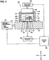
- FIG. 3 is a drawing showing a constitution of a manufacturing apparatus 100 used for the manufacturing of the coil component 10.
- FIG. 3 shows a cross-section of the manufacturing apparatus 100 and within the whole apparatus, hatchings are omitted with regard to a coil-assembly body 20, an admixture 200 and a press member 150 for the sake of convenience.
- the manufacturing apparatus 100 includes a base plate portion 110, a lower-side support plate 120, a cylindrical die 130, a lid member 140, a press member 150, a pressurizing mechanism 160, a vibration generating mechanism 170 and a control unit 180.
- the die 130 is a container which accommodates the coil-assembly body 20 and the admixture 200 containing magnetic powder and thermosetting resin.
- the press member 150 applies pressure to the admixture 200 inside the die 130.
- the vibration generating mechanism applies vibration to the admixture 200 inside the die 130 and the admixture 200 is filled inside the die 130.
- the manufacturing apparatus 100 of the first exemplified embodiment is provided with a depressurizing mechanism 190 which at least during the application of vibration by the vibration generating mechanism 170, sets an air pressure of the environment in which the admixture 200 is placed to be a negative-pressure lower than the atmospheric pressure.
- the control unit 180 controls the operation timings and the operation conditions of the pressurizing mechanism 160, the vibration generating mechanism 170 and the depressurizing mechanism 190.
- the wording of "filling” indicates that, compared with the state before the vibration-application, the admixture 200 is inputted into the inside of the inner cylindrical portion 132 (see FIG. 3 ), and it reaches up to every corner of the inner cylindrical portion 132 and the coil-assembly body 20 with fewer air gaps (voids) in it.
- the base plate portion 110 is a portion which becomes a base of the manufacturing apparatus 100 and is a portion for supporting the lower-side support plate 120 and the die 130.
- the base plate portion 110 is a portion which is applied with vibration by the vibration generating mechanism 170 which will be mentioned later.
- the vibration is applied to the admixture 200 in an inner cylindrical portion 132 of the die 130.
- This exhaust hole 111 communicates with an insertion hole 122 of the lower-side support plate 120 and it is possible to exhaust air from the inside to the outside of the inner cylindrical portion 132.
- the exhaust hole 111 is connected with the depressurizing mechanism 190 through an exhaust hose, a valve or the like, which is not shown.
- the admixture 200 it becomes difficult for the admixture 200 to penetrate into the insertion hole 122 caused by a configuration in which the insertion hole 122 is formed at a position facing the lower surface of the flange portion 31.
- the whole inside of the inner cylindrical portion 132 is pressurized and it becomes easy for the air within the inner cylindrical portion 132 to be exhausted from the insertion hole 122.
- the lower-side support plate 120 is a sheet-shaped or thin plate-shaped member and is a portion for sealing the opening portion on the lower side of the inner cylindrical portion 132 of the die 130.
- This lower-side support plate 120 is provided with positioning concave-portions 121 which are recessed compared with the upper surface of that lower-side support plate 120 and the terminal units 44a, 44b of the coil assembly body 20 enter into those positioning concave-portions 121.
- the position of the coil assembly body 20 with respect to the inner cylindrical portion 132 of the die 130 will be determined.
- the lower-side support plate 120 is provided with the insertion hole 122 and this insertion hole 122 communicates with the exhaust hole 111 mentioned above. For that reason, in a case of pressing the admixture 200 in the inner cylindrical portion 132 of the die 130, it is possible to exhaust the air which exists in the inner cylindrical portion 132 toward the outside through the exhaust hole 111 and the insertion hole 122.
- the die 130 is a member which includes a cylindrical outer cylindrical portion 131 and the portion surrounded by that outer cylindrical portion 131 (portion surrounded by an inner wall 131a of the outer cylindrical portion 131) becomes the inner cylindrical portion 132. Then, it is possible to place the coil assembly body 20 in this inner cylindrical portion 132, to fill the admixture 200 therein.
- the die 130 is positioned with respect to the lower-side support plate 120 through a positioning member which is not shown.
- a positioning member it is possible to cite, for example, a configuration in which a protrusion is provided at either one of the lower-side support plate 120 and the die 130 and a concave portion fitting into that protrusion is provided at the other one thereof. Also it is allowed to use another configuration for the positioning member.
- the inner wall 131a it is preferable for the inner wall 131a to be coated with a release agent beforehand. In a case of coating the release agent, it is possible, when carrying out an ejecting-step S408 mentioned later, to easily eject from the inner cylindrical portion 132 an integrated object formed by molding the admixture 200 and the coil assembly body 20.
- the lid member 140 is a member which is placed so as to cover the admixture 200 from the upward side (Z1 side) of the inner cylindrical portion 132 after the admixture 200 is filled in the inner cylindrical portion 132. It is preferable for this lid member 140 to be formed by a resin material having excellent mold-release characteristics. For one example of such a resin material, it is possible to use a fluorine resin material such as polytetrafluoroethylene (PTFE) or the like. It should be noted that there is no limitation for the thickness of the lid member 140 in particular, in which it is allowed to employ a member having a so-called sheet shape and other than this shape, a plate shape, a block shape or the like.
- PTFE polytetrafluoroethylene
- the lid member 140 is provided to be approximately the same as the shape of the inner cylindrical portion 132 when viewed in plan view and it is possible to press the admixture 200 which is filled in the inner cylindrical portion 132 excellently while preventing the admixture 200 from leaking from the gap between the lid member 140 and the inner wall 131a of the outer cylindrical portion 131.
- the press member 150 is a member for pressing the lid member 140 from the upper side thereof and is provided to have a smaller diameter than that of the lid member 140. For that reason, it is possible to prevent the press member 150 from colliding with the outer cylindrical portion 131. In addition, it is preferable for the press member 150 to be provided to have a larger thickness than that of the lid member 140. It is possible for the press member 150 to use, for example, a block-shaped member. However, the press member 150 is not to be limited to the block-shaped member and it is allowed to use, for example, an arm or the like which presses the lid member 140 toward one direction.
- the pressurizing mechanism 160 is a mechanism for applying a pressing force onto the press member 150 from the upper side of the press member 150. Owing to such a pressurizing mechanism 160, it becomes possible to pressurize the admixture 200 which exists in the inner cylindrical portion 132. It should be noted that it is allowed to employ a pressurizing mechanism 160 which applies a predetermined pressing force continuously and it is also allowed to employ a pressurizing mechanism which applies a predetermined pressing force periodically.
- the pressure is to be applied with respect to an area of from 1mm 2 to 30mm 2 per one product, in which it is preferred to apply a pressure of 0.01MPa or more and 20MPa or less onto such an area. Further, it is more preferable to apply a pressure of 0.5MPa or more and 2MPa or less.
- the vibration generating mechanism 170 is a mechanism which is attached to the base plate portion 110 and is a mechanism for applying a vibration with respect to that base plate portion 110.
- the vibration generating mechanism 170 corresponds to the vibration applying member. It is possible for the vibration generating mechanism 170 to employ, for example, a mechanism using a ball vibrator 171 and a compressor (not shown).
- the ball vibrator 171 is provided with an iron-steel-made iron ball and a cylindrical case for rotating the iron ball in which there is supplied a compressed air into the inside of the cylindrical case from a compressor.
- the iron ball rotates at high-speed, caused by the pressure of the compressed air which is supplied into the inside of the cylindrical case, and caused by that action, the vibration is applied to the base plate portion 110.
- the vibration applied to the base plate portion 110 is applied to the lower-side support plate 120, the die 130 and the admixture 200.
- the admixture 200 vibrates by the applied vibration and the molding-degree thereof becomes high.
- the wording "molding-degree” expresses "degree of being easily-molded” in which the material deforms and becomes another shape, wherein the state that the molding-degree is high indicates a state in which it is easy for that material to become a predetermined shape under a certain condition and the state that the molding-degree is low indicates a state in which it is difficult for that material to become a predetermined shape even under a similar condition.
- the molding-degree of the admixture 200 has a correlation with the applied vibration-frequency. The inventor etc.
- the vibration which it is preferable to apply to the base-plate portion 110 of the first exemplified embodiment has a frequency of, for example, 130Hz or more and 190Hz or less. It should be noted that it is allowed that the vibration applied to the admixture 200 of the first exemplified embodiment is to be caused by vibrating the base-plate portion 110 in a vertical direction or to be formed by vibration in a horizontal direction. In other words, it is allowed for the direction of the vibration to be a perpendicular direction with respect to the pressurizing direction of the pressurizing mechanism 160 and it is also allowed to be the same direction therewith.
- the admixture 200 enters into every corner of the inner cylindrical portion 132 and into air gaps of the coil-assembly body 20, into which the admixture 200 did not enter before the vibration-application. In addition, there exists no air gap or the like in the admixture 200 thereof.
- the ball vibrator 171 in which the iron ball does not move in a linear direction one-dimensionally but rotates, as mentioned above, in a circular orbit in the cylindrical case.
- the base plate portion 110 is applied with a vibration which is not linear but planar (two-dimensional) caused by the ball vibrator 171. Therefore, the admixture 200 can be filled into the air gap more excellently.
- the rotational surface formed by the rotation of the iron ball it is allowed for the rotational surface formed by the rotation of the iron ball to be set in parallel with the XY plane. Also it is allowed to let the rotational surface, to be in parallel with the Z direction, like a XZ plane or ZX plane is .
- the ball vibrator is also allowed for the ball vibrator to be mounted so as to be inclined with respect to the XY plane, the YZ plane or the ZX plane by a predetermined angle. Furthermore, there is no limitation of the mounting method thereof. Among those methods above, when vibrating the base-plate portion 110 toward the perpendicular direction with respect to the pressurizing direction of the pressurizing mechanism 160, it is possible to vibrate the admixture 200 by the vibration generating mechanism 170 preferably while maintaining the pressurizing state made by the pressurizing mechanism 160.
- the vibration generating mechanism 170 is not to be limited to a mechanism which uses the ball vibrator 171.
- the vibration generating mechanism 170 it is allowed for the vibration generating mechanism 170 to use a driving device of such a type in which the vibration is generated by mounting a rotational body onto a motor in an eccentric state and by rotating that rotational body.
- the vibration generating mechanism 170 it is possible for the vibration generating mechanism 170 to use various types of driving devices such as driving devices of ultrasonic methods, driving devices of such types using electromagnets and the like.
- the depressurizing mechanism 190 includes a vacuum pump communicating with the exhaust hole 111 which communicates with the inner cylindrical portion 132. It is allowed for the vacuum pump to have any constitution provided that the inside of the inner cylindrical portion 132 can be made to have a necessary degree of vacuum for filling the admixture 200. For the first exemplified embodiment, it is assumed that the depressurizing mechanism 190 has such an ability that it is possible to make the air pressure inside the inner cylindrical portion 132 to be from a pressure less than the atmospheric pressure to the atmospheric pressure. And specifically, it is assumed that there can be achieved a degree of vacuum from 10 -2 Pa or more until 10 5 Pa or less.
- a vacuum pump which can achieve such a degree of vacuum
- the depressurizing mechanism 190 to include a vacuum meter or the like which monitors the degree of vacuum in the inner cylindrical portion 132.
- the control unit 180 has a constitution for controlling the operations of the pressurizing mechanism 160, the vibration generating mechanism 170 and the depressurizing mechanism 190.
- the wording of “the operation of the pressurizing mechanism 160” indicates “the start of pressurizing”, “the end timing”, “applying the pressure to the lid member 140", and the like.
- the wording of “the operation of the vibration generating mechanism 170” indicates “the start of vibration-application”, “the end timing”, “the vibration frequency”, and “the direction” thereof.
- the wording of "the operation of the depressurizing mechanism 190” indicates “the start of depressurizing", “the end timing”, “controlling the air pressure inside the inner cylindrical portion 132", and the like.
- control unit 180 of the first exemplified embodiment it is allowed to employ a configuration of controlling each of the mechanisms automatically in accordance with a preset condition. And it is also allowed to employ a configuration in which an operator inputs or manually carries out at least a part of the operation.
- a control unit 180 can be realized also by using a general-purpose computer, a dedicated microcomputer or the like.
- FIG. 4 is a flowchart showing a manufacturing method of a coil component according to the first exemplified embodiment.
- the coil manufacturing method of the first exemplified embodiment is a manufacturing method of a coil component for forming a coil-assembly body 20 in which a coil is mounted on a magnetic-body core 30. As shown in FIG.
- the coil-assembly body 20 in the coil manufacturing method of the first exemplified embodiment, there exist the coil-assembly body 20; an input step (S401) for inputting the admixture 200 which includes the magnetic powder and the resin into the inner cylindrical portion 132 which is a container; a pressurizing step (S402) for applying pressure onto the admixture 200 which is inputted into the inner cylindrical portion 132, a depressurizing step (S403) for depressurizing an air pressure of the environment, in which the admixture 200 is placed, to become a negative-pressure lower than the atmospheric pressure at least during the pressurizing process in the pressurizing step (S402); a vibration-application step (S404) for applying vibration onto the admixture 200 and filling the admixture 200 in the inner cylindrical portion 132 at least during the depressurizing process in the depressurizing step (S403); and a curing step (S409) for curing the resin, which is contained in the admixture
- the wording of "at least during the pressurizing process in the pressurizing step” expresses that the depressurizing step S403 may start before the start of the pressurizing step 402 or may start after the start thereof.
- the wording of "at least during the depressurizing process in the depressurizing step” expresses that the vibration-application step S404 may start before the start of the depressurizing step S403 or may start after the start thereof.
- the explanation will be carried out by citing an example in which a thermosetting resin is used for the step S409. For this reason, in the abovementioned steps, all the steps other than the curing step S409 are carried out under the room temperature.
- the first exemplified embodiment is not to be limited to using a thermosetting resin and it is also allowed to use a two-component curing-type resin or a light-curing resin.
- the coil assembly body 20 is placed on the lower-side support plate 120 in the inner cylindrical portion 132, and the admixture 200 is inputted into the inside of the inner cylindrical portion 132. At that time, caused by a configuration in which the terminal units 44a, 44b are made to enter into positioning concave-portions of the lower-side support plate 120, which are not shown, the coil assembly body 20 is positioned in the inner cylindrical portion 132.
- the admixture 200 of the first exemplified embodiment is a putty-like admixture (in other words, clay-like admixture) obtained by mixing metal-made magnetic powders and a resin and by adding a solvent thereto. For that reason, for example, in a case of forming the admixture 200 to have a certain shape, the molding-degree thereof becomes an identical or similar viscosity as that of the clay and the shape thereof can be maintained.
- the magnetic cover portion 50 is formed by the admixture 200 and therefore, the magnetic powders and the resin are made by the same materials as those of the above-mentioned magnetic cover portion 50.
- the solvent it is possible for the solvent to arbitrarily utilize a well-known organic solvent such as acetone, MEK (methyl ethyl ketone), ethanol, ⁇ -Terpineol, IPA (isopropyl alcohol) or the like.
- a well-known organic solvent such as acetone, MEK (methyl ethyl ketone), ethanol, ⁇ -Terpineol, IPA (isopropyl alcohol) or the like.
- the admixture 200 there can be cited an admixture obtained by mixing the metal magnetic powders and the epoxy resin under a condition in which the composition ratio there-between is selected as 90:10 to 99:1 (including both of the end-values) by mass-ratio. Further, it is possible to prepare the viscosity of the admixture 200 by adding the solvent selectively.
- the metal magnetic powders it is possible to cite powders in which amorphous metal magnetic powders containing at least iron, silicon, chromium and carbon are mixed with iron-silicon chromium based alloy powders by mass-ratio 1:1.
- a terpineol for the solvent which is added to the admixture 200 in which the additive amount of the solvent is made to be less than 5wt% with respect to the mass of the admixture 200.
- the viscosity of the admixture 200 becomes within a range of 30Pa ⁇ s to 3000Pa ⁇ s.
- the block body of the admixture 200 is formed beforehand so as to obtain a proper amount of the admixture 200 and, in addition, so as to form a shape which is easily inputted to the inner cylindrical portion 132. Then, after placing the coil assembly body 20 on the lower-side support plate 120, the block body of the admixture 200 is placed on the upper portion of the coil assembly body 20.
- the pressurizing step S402 is carried out.
- the lid member 140 is placed on the upper portion of the admixture 200 and after placing the press member 150 on the upper portion of the lid member 140, the pressurizing mechanism 160 is activated.
- the lid member 140 is pressed by the pressurizing mechanism 160 toward the Z2 direction shown in FIG. 3 and the pressurizing mechanism 160 applies pressure onto the admixture 200.
- the pressurized admixture 200 enters into the air gap inside the inner cylindrical portion 132 and is to be filled into the inside of the inner cylindrical portion 132.
- Such a pressurizing step S402 of this exemplified embodiment is a step in which the inner cylindrical portion 132 is filled with the admixture 200 without substantially changing the volume of the admixture 200 eliminating the air gap thereof.
- the pressurizing step S402 is designed to be different from a well-known compression-step in which the processed-object such as ferrite, iron powder or the like is compressed by high pressure and the volume thereof is reduced significantly.
- the pressurizing step S402 of the first exemplified embodiment if a pressing pressure of, for example, around 0.5kg/cm2 to 50kg/cm2 is to be loaded onto the admixture 200. Therefore, in the pressurizing step S402, also the damage to the die 130 becomes less compared with the well-known compression step and there can be obtained such a merit that the selective range of the material for the die 130 will be widened.
- the position of the press member 150 is maintained also during the succeeding step of depressurizing or the like and the pressure is kept on being applied to the admixture 200.
- the depressurizing step S403 is carried out.
- the depressurizing step there is maintained the state in which the pressurizing mechanism 160 pressurized the press member 150 and the lid member 140. It means that the maintenance of this pressurizing state is one part of the pressurizing step S402 and that it is also a part of the vibration-application step S404.
- the control unit 180 activates the depressurizing mechanism 190 while the admixture 200 is pressurized.
- the depressurizing mechanism 190 sets the air pressure inside the inner cylindrical portion 132 to be, for example, 100Pa or more and 104Pa or less.
- the air pressure inside the inner cylindrical portion 132 is determined according to the balance between the exhaust ability of the depressurizing mechanism 190 and the flow-rate (air tightness in the inner cylindrical portion 132) of the atmospheric air which flows into the inside of the inner cylindrical portion 132.
- the vibration-application step S404 of the first exemplified embodiment is a step for applying vibration to the admixture 200.
- the control unit 180 controls the vibration generating mechanism 170 and the application of the vibration with respect to the admixture 200 is started.
- the admixture 200 is pressurized and the internal pressure therein becomes a depressurized state.
- the vibration is applied to the base-plate portion 110 and the applied vibration is also transmitted to the admixture 200.
- the amplitude thereof is designed to be within a range of 0.1 ⁇ m to 1cm.
- the frequency of the applied vibration is designed to be within a range of 2Hz to 500Hz. Within such a range, it is preferable, for the first exemplified embodiment, to apply a vibration, whose frequency is particularly 130Hz or more and 190Hz or less, to the admixture 200.
- the time period for applying the vibration by the vibration generating mechanism 170 is designed to be within a range of 1 second to 300 seconds. It should be noted that the time period for applying the vibration is not to be limited to the above-mentioned range and it is allowed to vibrate the admixture 200, for example, for more than 100 seconds.
- the molding-degree thereof becomes high rapidly. For that reason, when the molding-degree of the admixture 200 became high rapidly, by pressurizing the admixture 200 in one direction under the condition mentioned above. And by depressurizing the ambient pressure, the admixture 200 enters into the air gaps sufficiently in the inner cylindrical portion 132 and is filled in the inner cylindrical portion 132 fully. In addition, by pressurizing the admixture 200 and placing it under a depressurizing environment, the air gaps occurring in the admixture 200 are crushed and will disappear. Caused by such a phenomenon, it happens that in the first exemplified embodiment, the admixture 200 will cover the whole circumference of the coil-assembly body 20 without any air gaps and it is possible to eliminate the filling defect.
- the control unit 180 judges the end timings of those respective steps (S405). It is allowed to judge the end timing of each step, for example, by a predetermined time-lapse from the start of the each step. In addition, it is allowed to employ a configuration for the respective end timings of the steps in which the vibration-stopping step S406 and the depressurizing step S407 sequentially in this order.
- the depressurizing step S403, the vibration-application step S404, the vibration-stopping step S406 and the depressurizing step S407 are not limited to a configuration of being carried out by the sequential order shown in the flow chart of FIG. 4 .
- it is allowed to start the depressurizing step S403 and the vibration-application step S404 to simultaneously and it is also allowed to carry out the vibration-application step S404 preceding to the depressurizing step S403.
- the lid member 140 is a member closable when applying the pressure to the admixture 200, it is allowed to carry out the pressurizing step S402 simultaneously in addition to the depressurizing step S403 and the vibration-application step S404.
- the ejecting-step S408 is carried out.
- the pressurization of the admixture 200 is released by a configuration in which the control unit 180 controls the pressurizing mechanism 160 and the press member 150 is lifted up toward the Z1 direction shown in FIG. 3 .
- the integrated object of the admixture 200 and the coil-assembly body 20 is ejected from the inside of the inner cylindrical portion 132.
- the top surface portion of the admixture 200 is in close contact with the lid member 140 and therefore, it is possible to eject the integrated object when the upper surface is in close contact with the lid member 140 by pushing the integrated object upward, for example, by inserting a pin shaped push-up member into the lower surface of the integrated body in the inner cylindrical portion 132.
- the curing step S409 is carried out.
- the admixture 200 in the ejected integrated object is thermally-cured by being heated up to the thermosetting temperature or more.
- the solvent contained in the admixture 200 is removed by being volatilized.
- the lid member 140 is removed from the upper surface of the integrated object.
- the coil component 10 is formed.
- the ejecting-step S408 and the curing step S409 that it is not to be limited to carrying out such a procedure as mentioned above. More specifically, it is allowed, before carrying out the ejecting-step S408, to carry out the curing step S409 when the integrated object is filled in the inner cylindrical portion 132. Then, it is allowed, after curing the integrated object completely in the curing step S409, to carry out the ejecting-step S408.
- the curing step S409 of the first stage is carried out at a first temperature before carrying out the ejecting-step S408, in which the admixture 200 of the integrated object is to be semi-cured.
- the first temperature is selected to be less than the thermosetting temperature of the thermosetting resin
- the first temperature is made to be a temperature by which the solvent contained in the admixture 200 is volatilized so as to semi-cure the integrated object.
- the ejecting-step S408 is carried out and the integrated object containing the semi-cured admixture 200 is ejected from the inner cylindrical portion 132.
- the curing step S409 of the second stage is carried out at a second temperature which is higher than the first temperature.
- the second temperature made to be equal to or higher than the thermal-cure temperature of the thermosetting resin. It should be noted that it is allowed for the first temperature to be equal to or higher than a curing start temperature of the thermosetting resin and also lower than a complete curing temperature.
- a post-treatment step after carrying out the curing step S409.
- processes such as a polishing step of the surface of the magnetic cover portion 50, a coating-formation step by using a thermosetting resin or the like, and the like.
- the putty-like admixture 200 has a high viscosity and even if the admixture 200 inputted into the inner cylindrical portion 132 is pressurized, there is a fear that a place which is not sufficiently filled with the admixture 200 (filling defect) is caused in the inner cylindrical portion 132.
- the depressurizing step S403 is carried out and the admixture 200 is pressed onto the inner wall of the inner cylindrical portion 132, and concurrently, the vibration-application step S404 is carried out and the molding-degree of the admixture 200 is heightened.
- the wording "molding-degree” expresses “degree of being easily-molded” in which the material deforms and becomes another shape and therefore, the admixture 200, whose molding-degree is heightened, deforms in conformity with the shapes of the inner cylindrical portion 132 and the coil-assembly body 20 and it becomes easy for the admixture to enter into the air gaps of the inner cylindrical portion 132 and the air gaps of the coil-assembly body 20. Therefore, in the first exemplified embodiment, it is possible to prevent the places which are not filled with the admixture 200 (filling defect) from occurring in the inner cylindrical portion 132. In such a first exemplified embodiment, it is possible to uniformize the quality of the coil component 10 which is formed by way of the subsequent ejecting-step S408, curing step S409 and the like.
- FIG. 5 is a drawing for explaining a manufacturing method of a coil component according to a second exemplified embodiment of the present invention.
- the second exemplified embodiment with regard to similar constitutions as the constitutions which were explained in the first exemplified embodiment, similar reference numerals are applied thereto and the explanations and illustrations thereof will be omitted.
- the manufacturing method of the coil component in the second exemplified embodiment is a method having a configuration, for the depressurizing step S403 in the first exemplified embodiment, in which a mold body 60, which includes cavity portions 62 corresponding to a plurality of containers, is depressurized at once in a depressurizing chamber 300 which can accommodate the plurality of containers.
- the manufacturing apparatus (400) of a coil component in the second exemplified embodiment includes a mold body 60 provided with a plurality of cavity portions 62; a base-plate portion 310 which supports the mold body 60; a lid member 141 which pressurizes the admixture 200 inputted into the mold body 60; a press member 151; and a pressurizing mechanism 161.
- the mold body 60, the base-plate portion 310 and the lid member 141 are housed in the depressurizing chamber 300.
- an exhaust hole 311 is formed at the base-plate portion 310 and there is included a depressurizing mechanism 191 which depressurizes the inside of the depressurizing chamber 300 through the exhaust hole 311.
- the manufacturing apparatus 400 includes a vibration generating mechanism 173 which applies a vibration to the admixture 200 through the base-plate portion 310, a pressurizing mechanism 161 and a control unit 180 which controls the operations of the depressurizing mechanism 191, the vibration generating mechanism 173 and the pressurizing mechanism 161.
- exhaust paths which communicate with the respective cavity portions 62 and the exhaust hole 311 are formed in the mold body 60 and when the depressurizing mechanism 191 starts the exhausting, the air is exhausted, by the depressurizing mechanism 191, from the inside of the cavity portion 62 by passing through the exhaust hole 311.
- the mold body 60 is formed by a resin material having a good mold-releasing property.
- a resin material of the mold body 60 it is possible to cite a silicone rubber material as an example.
- the mold body 60 has a constitution in which an integrated jig 59 and a bottom portion 64 are formed integrally.
- the mold body 60 has flexibility and also is provided with a plurality of arranged cavity portions 62. In the input step S401 shown in FIG. 4 , each of the plurality of cavity portions 62 is inputted with the admixture 200 and the coil-assembly body 20.
- the coil-assembly body 20 is inputted into the cavity portion 62 and the coil-assembly body 20 is fixed by being fitted in a concave portion (not-shown) which is provided at the bottom surface of the cavity portion 62. Then, the admixture 200 is inputted into the cavity portion 62.
- the mold body 60 is attached with the lid member 141 and the press member 151 is placed on the lid member 141.
- the control unit 180 pressurizes the admixture 200 by the pressurizing mechanism 161 and subsequently, the inside of the depressurizing chamber 300 is depressurized by the depressurizing mechanism 191, and the vibration is applied to the admixture 200 through the base-plate portion 310 by controlling the vibration generating mechanism 173.
- the second exemplified embodiment it is possible for the second exemplified embodiment to manufacture integrated objects formed by the plurality of coil-assembly bodies 20 and the admixtures 200 simultaneously in the plurality of cavity portions 62.
- thermosetting resin for the resin similarly to the first exemplified embodiment.
- the second exemplified embodiment is not to be limited either by using the thermosetting resin for the resin and it is also allowed for the resin to use, inter alia, a two-component curing-type resin or a light-curing resin.
- the plurality of coil components 10 see FIG. 1 , FIG.
- This experimental example is an example presenting the result obtained by an experiment with regard to a matter that the molding-degree of the admixture 200 will become high by applying the vibration while pressurizing the admixture 200.
- FIG. 6 is a drawing for explaining an apparatus which was used for the experiment of this example.
- the apparatus shown in FIG. 6 includes a cylinder 63 and a pressurizing pin 61 which pressurizes the admixture 200 in the cylinder 63.
- a vibration V whose frequency changes continuously while there is applied a pressure by the pressurizing pin 61.
- the cylinder 63 is formed with a discharge port 65 and the admixture 200 applied with the pressure and the vibration is discharged from the discharge port 65 to the outside of the cylinder 63.
- the discharge amount of the admixture 200 changes depending on the molding-degree of the admixture 200 and it is conceivable that the lower the molding-degree is the greater the discharge amount becomes.
- the inner diameter of the discharge port 65 was made to be 2.0mm.
- the frequency range of the vibration V was made to be from 70Hz to 210Hz.
- the pressurizing pin 61 applies a pressure of 0.5MPa or more and 2MPa or less with respect to the admixture 200.
- the viscosity of the admixture 200 is in a range of 107cPs or more and 1012cPs or less, more preferably, in a range of 3 ⁇ 1010cPs or more and 1011cPs or less.
- the range of the resin content is from 5Vol% or more to 80Vol% or less.
- the pressure and the vibration V are applied to the admixture 200 for 60 seconds.
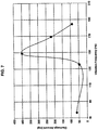
- FIG. 7 is a graph presenting the result obtained by an experiment that was carried out by using the apparatus shown in FIG. 6 .
- the horizontal axis of the graph shown in FIG. 6 indicates the frequency (vibration number) of the vibration V which was applied to the admixture 200, and the vertical axis thereof indicates the amount of the admixture 200 which was discharged from the discharge port 65 during the application of the pressure and the vibration V.
- the discharge amount of the admixture 200 ascends with a steep inclination from around a frequency exceeding 130Hz and reaches a peak at 150Hz.
- the discharge amount descends comparatively steeply after exceeding the frequency 150Hz of the vibration V.
- FIG. 7 it is understood, in this experimental example, that it is possible to heighten the molding-degree of the admixture 200 efficiently by applying a frequency of 140Hz or more and 190Hz or less onto the admixture 200.
Landscapes
- Engineering & Computer Science (AREA)
- Power Engineering (AREA)
- Manufacturing & Machinery (AREA)
- Microelectronics & Electronic Packaging (AREA)
- Physics & Mathematics (AREA)
- Electromagnetism (AREA)
- Chemical & Material Sciences (AREA)
- Dispersion Chemistry (AREA)
- Manufacturing Cores, Coils, And Magnets (AREA)
- Coils Or Transformers For Communication (AREA)
- Insulating Of Coils (AREA)
Abstract
Description
- The present invention contains subject matter related to Japanese Patent Application
JP2017-025959 - The present invention relates to a manufacturing method of a coil component and a manufacturing apparatus of a coil component.
- There have been proposed various kinds of coil components each of which includes a magnetic core and a winding-wire coil. Among such coil components, there exists a component in which a coil formed by winding a rectangular wire or the like is attaching onto a magnetic-body core formed by a magnetic-body and in which there is further provided a magnetic cover portion which covers those members (see Patent Document 1: Chinese unexamined patent publication No.
103151139 ). This magnetic cover portion is formed by filling the inside of a mold with an admixture which is obtained by mixing metal-made magnetic powders and a resin by using an injection molding technique in a molten state, and then, by employing a mold-forming process using a magnetic material. - Meanwhile, it is required for the constitution as mentioned above that filling defects of the admixture would not occur at the periphery or the like of the coil on an occasion of mass-producing the coil components. For that reason, it is conceivable to pressurize the admixture. However, the admixture mentioned above has a comparatively high viscosity and even if the admixture thereof is pressurized, there may be a space which is not sufficiently filled with the admixture (filling defect) in the mold. The filling defect of the admixture becomes one reason of a fluctuation which occurs in the quality of the coil component.
- The present invention was invented in view of such a problem and is addressed to providing a manufacturing method of a coil component and a manufacturing apparatus of a coil component in which it is possible to decrease the filling defect of the admixture.
- The manufacturing method of a coil component according to one embodiment of the present invention is characterized by a manufacturing method of a coil component for forming a coil-assembly body in which a coil is mounted on a magnetic-body core, including the steps of: inputting the coil-assembly body and an admixture containing a magnetic powder and a resin into a container; applying pressure onto the admixture which is inputted into the container; depressurizing an air pressure of an environment, in which the admixture is placed, to become a negative-pressure lower than the atmospheric pressure at least during the pressurizing process in the step of applying pressure; applying vibration onto the admixture and filling the admixture in the container at least during the depressurizing process in the step of depressurizing; and curing the resin contained in the admixture for the integrated object of the admixture and the coil-assembly body which passed through the step of depressurizing and the step of applying vibration.
- The manufacturing apparatus of a coil component according to one embodiment of the present invention is characterized by a manufacturing apparatus of a coil component for forming a coil-assembly body in which a coil is mounted on a magnetic-body core, including: a container housing the coil-assembly body and an admixture containing a magnetic powder and a resin; a press member applying pressure to the admixture inside the container; a vibration generating mechanism which applies vibration to the admixture inside the container and which fills the admixture in the container; and a depressurizing mechanism depressurizing the environment, in which the admixture is placed, to become a negative-pressure environment lower than the atmospheric pressure at least during the application of the vibration by the vibration generating mechanism.
- According to the present invention, it becomes possible to provide a manufacturing method of a coil component and a manufacturing apparatus of a coil component, in which it is possible to decrease filling defects of the admixture.
-
-
FIG. 1 is a perspective view transparently showing an internal constitution of a coil component relating to a first exemplified embodiment of the present invention; -
FIG. 2 is a cross-sectional view along an arrow B-B shown inFIG. 1 ; -
FIG. 3 is a drawing showing a manufacturing apparatus of a coil component according to a first exemplified embodiment of the present invention; -
FIG. 4 is a flowchart showing a manufacturing method of a coil component according to the first exemplified embodiment of the present invention; -
FIG. 5 is a drawing showing a manufacturing method of a coil component according to a second exemplified embodiment of the present invention; -
FIG. 6 is a drawing for explaining an inventive example of the present invention; and -
FIG. 7 is a graph for explaining the result of the inventive example shown inFIG. 6 . - Hereinafter, there will be explained a manufacturing method and a manufacturing apparatus of a
coil component 10 of a first exemplified embodiment of the present invention. In the following explanation, there will be used the XYZ orthogonal coordinate system if it is necessary. In the XYZ orthogonal coordinate system, "X direction" indicates a direction in whichterminals FIG. 1 in which "X1 side" indicates the right front inFIG. 1 and "X2 side" indicates the left rear side which is opposite thereto. In addition, "Y direction" indicates a direction in which theterminals lower bottom surface 31C in which "Y1 side" indicates the right rear side inFIG. 1 and "Y2 side" indicates the left front side which is opposite thereto. In addition, "Z direction" indicates the axis direction of a pillar-shaped core portion 32 in which "Z1 side" indicates the upper side thereof and "Z2 side" indicates the lower side thereof. - First, prior to the explanation of the manufacturing method and the manufacturing apparatus of the
coil component 10 of the first exemplified embodiment, there will be explained thecoil component 10 which is manufactured by the manufacturing method and the manufacturing apparatus of the first exemplified embodiment. -
FIG. 1 is a perspective view transparently showing an internal constitution of acoil component 10 relating to a first exemplified embodiment of the present invention.FIG. 2 is a cross-sectional view along an arrow B-B shown inFIG. 1 . InFIG. 2 , there is shown a cross-section of only themagnetic cover portion 50. And a coil-assembly body 20 is shown by a side view thereof. - The
coil component 10 in the first exemplified embodiment constitutes an electronic component such as an inductor, a transformer, a choke coil or the like. Thecoil component 10 is formed by including thecoil assembly body 20 and themagnetic cover portion 50 as main constituent elements. Thecoil assembly body 20 includes a magnetic-body core 30 and acoil 40. - The magnetic-
body core 30 is provided with aflange portion 31 and a pillar-shaped core portion 32, integrally. The magnetic-body core 30 is formed by a material of a ferrite core which is obtained by sintering ferrite or of a dust core which is obtained by compression-molding magnetic powders. Here, for the magnetic powders of the dust core, it is possible to use magnetic powders whose main component is iron (Fe) and into which each of silicon (Si) and chromium (Cr) is added by a ratio of 1wt% or more and 10wt% or less. The magnetic powders are excellent in the aspects of rust-prevention property, relative permeability and the like. From the viewpoint of decreasing the core loss, it is allowed for the magnetic-body core 30 to be constituted by metal magnetic powders which are obtained by mixing the magnetic powders with an amorphous metal. For the amorphous metal, it is possible to use a carbon-contained amorphous metal whose main component is iron (Fe), in which each of silicon (Si) and chromium (Cr) is contained by a ratio of 1wt% or more and 10wt% or less, and further, in which carbon (C) is contained by a ratio of 0.1wt% or more and 5wt% or less. Further, in the first exemplified embodiment, it is also allowed for the magnetic-body core 30 to be formed so as to contain manganese (Mn) therein. - The
flange portion 31 has a plate shape and according to the constitution shown inFIG. 1 , the planar shape of theflange portion 31 forms approximately a square shape. However, the planar shape of theflange portion 31 is not to be limited to the "approximately square shape" and it is possible to employ various kinds of shapes such as a circle shape, an elliptical shape, a polygonal shape and the like. In addition, at the center portion of theflange portion 31, there is provided the pillar-shaped core portion 32 in a standing fashion. The pillar-shaped core portion 32 has a cylindrical shape stretching so as to be directed to the upward side (Z1 side), but it is allowed to employ a shape other than the cylindrical shape (to employ a polygonal prism such as a quadrangular prism or the like). The pillar-shaped core portion 32 is plugged into acoil hole 42a of thecoil 40 which will be mentioned later. - In addition, for the
coil 40, there is used a rectangular wire 41 (corresponding to conductive wire) whose width size is sufficiently larger than the thickness size thereof in which awinding wire portion 42 is formed by winding therectangular wire 41 and thecoil hole 42a is provided on the inner circumferential side of thewinding wire portion 42. Into thecoil hole 42a, the pillar-shaped core portion 32 mentioned above is plugged. It should be noted that according to the constitution shown inFIGS. 1 and2 , thewinding wire portion 42 is formed by an edgewise winding in which the axis direction of thatwinding wire portion 42 is provided so as to be in conformity with the axis direction of the pillar-shaped core portion 32. In addition, it is allowed for the lower surface side of the windingwire portion 42 to be fixed with respect to the upper surface of theflange portion 31 by an adhesive agent. For such an adhesive agent, it is possible to use an insulating-resin adhesive agent. - One
terminal 43a of therectangular wire 41 extends from the upper surface side of thewinding wire portion 42 toward a direction (Y1 side) in parallel with theupper surface 31A of theflange portion 31 of the magnetic-body core 30 and thereafter, abuts against aside surface 31B on the Y1 side of theflange portion 31 inFIG. 2 in parallel therewith and, further, is bent so as to be directed toward the Y2 side while being abutted against thelower bottom surface 31C of theflange portion 31. The portion abutted against thelower bottom surface 31C is exposed downward from themagnetic cover portion 50 and becomes aterminal unit 44a which will be electrically connected to another substrate or the like. Further, theterminal unit 44a is bent so as to be directed upward while being abutted against theside surface 31D on the Y2 side of theflange portion 31 and finally, is bent so as to be inclined toward the side of the pillar-shaped core portion 32 of theflange portion 31. - Similarly, the
other terminal 43b of therectangular wire 41 extends from the lower surface side of thewinding wire portion 42 toward a direction (Y1 side) in parallel with the upper surface of theflange portion 31 and thereafter, abuts against aside surface 31B on the Y1 side of theflange portion 31 inFIG. 1 in parallel therewith and further, is bent so as to be directed toward the Y2 side while being abutted against thelower bottom surface 31C of theflange portion 31. It should be noted that the portion abutted against thislower bottom surface 31C is exposed downward from themagnetic cover portion 50 and becomes aterminal unit 44b which will be electrically connected to another substrate or the like. Such a portion becomes theterminal unit 44b, further, is bent so as to be directed upward while being abutted against theside surface 31D on the Y2 side of theflange portion 31 and finally, is bent so as to be inclined toward the pillar-shaped core portion 32 side of theflange portion 31. - It should be noted that it is also allowed to employ a configuration in which on the
lower bottom surface 31C of theflange portion 31, there are provided groove portions (not shown) so as to sag upward for inducing theterminal units rectangular wire 41 and each electrode groove houses a portion of the thickness of theterminal unit 44a (44b). For that reason, the downward sides of theterminal units lower bottom surface 31C. It is allowed for the upper surface sides of theterminal units - The conductive wire can be a round wire having a circular cross-section shape instead of the
rectangular wire 41 mentioned above. In that case, theterminal units - In addition, on the
side surface 31D on the Y2 side of theflange portion 31, there are formed side-surface concave portions (not shown) for positioning theterminals terminals terminals flange portion 31. In addition, theterminals - Next, there will be explained the
magnetic cover portion 50. Themagnetic cover portion 50 is formed by a material containing magnetic powders and a thermosetting resin. For the magnetic powder, it can use a similar material as that of the magnetic-body core 30 mentioned above and it is also allowed to use a different material. In addition, for the resin, a resin which is to be cured under a specific condition is enough, for example any one of a thermosetting resin. That is, a two-component curing-type resin, or a light-curing resin which is cured by an irradiation of UV light or the like is fit for the purpose. When using a thermosetting resin as the resin, the thermosetting resin, for example, an epoxy resin, a phenol resin or a silicon resin can be used. - The
magnetic cover portion 50 is provided so as to cover thecoil assembly body 20 totally except theterminal units lower bottom surface 31C of theflange portion 31 to be exposed. And it is also allowed for another portion other than thelower bottom surface 31C and theterminal units coil assembly body 20 to be exposed. As shown inFIG. 1 , themagnetic cover portion 50 is provided approximately in a rectangular shape. However, the shape of themagnetic cover portion 50 can be an arbitrary shape. And the shape thereof is not limited to the "approximately rectangular shape". Themagnetic cover portion 50 is provided so as to cover the pillar-shapedcore portion 32 of the magnetic-body core 30 and the windingwire portion 42 of thecoil 40. - Next, there will be explained a constitution of a manufacturing apparatus of a coil component 100 (hereinafter, also described merely as "manufacturing apparatus" 100), which is used in order to manufacture the
coil component 10. -
FIG. 3 is a drawing showing a constitution of amanufacturing apparatus 100 used for the manufacturing of thecoil component 10.FIG. 3 shows a cross-section of themanufacturing apparatus 100 and within the whole apparatus, hatchings are omitted with regard to a coil-assembly body 20, anadmixture 200 and apress member 150 for the sake of convenience. Themanufacturing apparatus 100 includes abase plate portion 110, a lower-side support plate 120, acylindrical die 130, alid member 140, apress member 150, apressurizing mechanism 160, avibration generating mechanism 170 and acontrol unit 180. Within such a constitution, thedie 130 is a container which accommodates the coil-assembly body 20 and theadmixture 200 containing magnetic powder and thermosetting resin. Thepress member 150 applies pressure to theadmixture 200 inside thedie 130. The vibration generating mechanism applies vibration to theadmixture 200 inside thedie 130 and theadmixture 200 is filled inside thedie 130. Further, themanufacturing apparatus 100 of the first exemplified embodiment is provided with adepressurizing mechanism 190 which at least during the application of vibration by thevibration generating mechanism 170, sets an air pressure of the environment in which theadmixture 200 is placed to be a negative-pressure lower than the atmospheric pressure. Thecontrol unit 180 controls the operation timings and the operation conditions of thepressurizing mechanism 160, thevibration generating mechanism 170 and thedepressurizing mechanism 190. - Within the contents mentioned above, according to the present specification, the wording of "filling" indicates that, compared with the state before the vibration-application, the
admixture 200 is inputted into the inside of the inner cylindrical portion 132 (seeFIG. 3 ), and it reaches up to every corner of the innercylindrical portion 132 and the coil-assembly body 20 with fewer air gaps (voids) in it. - Hereinafter, there will be explained such respective constitutions sequentially.
- The
base plate portion 110 is a portion which becomes a base of themanufacturing apparatus 100 and is a portion for supporting the lower-side support plate 120 and thedie 130. In addition, thebase plate portion 110 is a portion which is applied with vibration by thevibration generating mechanism 170 which will be mentioned later. Caused by the application of vibration to such abase plate portion 110, the vibration is applied to theadmixture 200 in an innercylindrical portion 132 of thedie 130. It should be noted in the constitution shown inFIG. 3 that there is formed anexhaust hole 111 at thebase plate portion 110. Thisexhaust hole 111 communicates with aninsertion hole 122 of the lower-side support plate 120 and it is possible to exhaust air from the inside to the outside of the innercylindrical portion 132. Theexhaust hole 111 is connected with thedepressurizing mechanism 190 through an exhaust hose, a valve or the like, which is not shown. - As shown in
FIG. 3 , in the first exemplified embodiment, it becomes difficult for theadmixture 200 to penetrate into theinsertion hole 122 caused by a configuration in which theinsertion hole 122 is formed at a position facing the lower surface of theflange portion 31. In addition, caused by a configuration in which theinsertion hole 122 is arranged on the side opposite to thelid member 140, the whole inside of the innercylindrical portion 132 is pressurized and it becomes easy for the air within the innercylindrical portion 132 to be exhausted from theinsertion hole 122. - The lower-
side support plate 120 is a sheet-shaped or thin plate-shaped member and is a portion for sealing the opening portion on the lower side of the innercylindrical portion 132 of thedie 130. This lower-side support plate 120 is provided with positioning concave-portions 121 which are recessed compared with the upper surface of that lower-side support plate 120 and theterminal units coil assembly body 20 enter into those positioning concave-portions 121. Thus, the position of thecoil assembly body 20 with respect to the innercylindrical portion 132 of thedie 130 will be determined. - In addition, the lower-
side support plate 120 is provided with theinsertion hole 122 and thisinsertion hole 122 communicates with theexhaust hole 111 mentioned above. For that reason, in a case of pressing theadmixture 200 in the innercylindrical portion 132 of thedie 130, it is possible to exhaust the air which exists in the innercylindrical portion 132 toward the outside through theexhaust hole 111 and theinsertion hole 122. - The
die 130 is a member which includes a cylindrical outercylindrical portion 131 and the portion surrounded by that outer cylindrical portion 131 (portion surrounded by aninner wall 131a of the outer cylindrical portion 131) becomes the innercylindrical portion 132. Then, it is possible to place thecoil assembly body 20 in this innercylindrical portion 132, to fill theadmixture 200 therein. - It should be noted that the
die 130 is positioned with respect to the lower-side support plate 120 through a positioning member which is not shown. For such a positioning member, it is possible to cite, for example, a configuration in which a protrusion is provided at either one of the lower-side support plate 120 and thedie 130 and a concave portion fitting into that protrusion is provided at the other one thereof. Also it is allowed to use another configuration for the positioning member. In addition, it is preferable for theinner wall 131a to be coated with a release agent beforehand. In a case of coating the release agent, it is possible, when carrying out an ejecting-step S408 mentioned later, to easily eject from the innercylindrical portion 132 an integrated object formed by molding theadmixture 200 and thecoil assembly body 20. - The
lid member 140 is a member which is placed so as to cover theadmixture 200 from the upward side (Z1 side) of the innercylindrical portion 132 after theadmixture 200 is filled in the innercylindrical portion 132. It is preferable for thislid member 140 to be formed by a resin material having excellent mold-release characteristics. For one example of such a resin material, it is possible to use a fluorine resin material such as polytetrafluoroethylene (PTFE) or the like. It should be noted that there is no limitation for the thickness of thelid member 140 in particular, in which it is allowed to employ a member having a so-called sheet shape and other than this shape, a plate shape, a block shape or the like. In addition, thelid member 140 is provided to be approximately the same as the shape of the innercylindrical portion 132 when viewed in plan view and it is possible to press theadmixture 200 which is filled in the innercylindrical portion 132 excellently while preventing theadmixture 200 from leaking from the gap between thelid member 140 and theinner wall 131a of the outercylindrical portion 131. - The
press member 150 is a member for pressing thelid member 140 from the upper side thereof and is provided to have a smaller diameter than that of thelid member 140. For that reason, it is possible to prevent thepress member 150 from colliding with the outercylindrical portion 131. In addition, it is preferable for thepress member 150 to be provided to have a larger thickness than that of thelid member 140. It is possible for thepress member 150 to use, for example, a block-shaped member. However, thepress member 150 is not to be limited to the block-shaped member and it is allowed to use, for example, an arm or the like which presses thelid member 140 toward one direction. - The
pressurizing mechanism 160 is a mechanism for applying a pressing force onto thepress member 150 from the upper side of thepress member 150. Owing to such apressurizing mechanism 160, it becomes possible to pressurize theadmixture 200 which exists in the innercylindrical portion 132. It should be noted that it is allowed to employ apressurizing mechanism 160 which applies a predetermined pressing force continuously and it is also allowed to employ a pressurizing mechanism which applies a predetermined pressing force periodically. - For the
pressurizing mechanism 160 of the first exemplified embodiment, it is supposed that the pressure is to be applied with respect to an area of from 1mm2 to 30mm2 per one product, in which it is preferred to apply a pressure of 0.01MPa or more and 20MPa or less onto such an area. Further, it is more preferable to apply a pressure of 0.5MPa or more and 2MPa or less. - The
vibration generating mechanism 170 is a mechanism which is attached to thebase plate portion 110 and is a mechanism for applying a vibration with respect to thatbase plate portion 110. Thevibration generating mechanism 170 corresponds to the vibration applying member. It is possible for thevibration generating mechanism 170 to employ, for example, a mechanism using aball vibrator 171 and a compressor (not shown). Theball vibrator 171 is provided with an iron-steel-made iron ball and a cylindrical case for rotating the iron ball in which there is supplied a compressed air into the inside of the cylindrical case from a compressor. The iron ball rotates at high-speed, caused by the pressure of the compressed air which is supplied into the inside of the cylindrical case, and caused by that action, the vibration is applied to thebase plate portion 110. - The vibration applied to the
base plate portion 110 is applied to the lower-side support plate 120, thedie 130 and theadmixture 200. Theadmixture 200 vibrates by the applied vibration and the molding-degree thereof becomes high. Here, the wording "molding-degree" expresses "degree of being easily-molded" in which the material deforms and becomes another shape, wherein the state that the molding-degree is high indicates a state in which it is easy for that material to become a predetermined shape under a certain condition and the state that the molding-degree is low indicates a state in which it is difficult for that material to become a predetermined shape even under a similar condition. The molding-degree of theadmixture 200 has a correlation with the applied vibration-frequency. The inventor etc. of the present invention found out a range of the vibration frequency which largely improves the molding-degree of theadmixture 200 and by using this frequency, the vibration is applied to the base-plate portion 110. The vibration which it is preferable to apply to the base-plate portion 110 of the first exemplified embodiment has a frequency of, for example, 130Hz or more and 190Hz or less. It should be noted that it is allowed that the vibration applied to theadmixture 200 of the first exemplified embodiment is to be caused by vibrating the base-plate portion 110 in a vertical direction or to be formed by vibration in a horizontal direction. In other words, it is allowed for the direction of the vibration to be a perpendicular direction with respect to the pressurizing direction of thepressurizing mechanism 160 and it is also allowed to be the same direction therewith. - By the fact that the molding-degree is increased, the
admixture 200 enters into every corner of the innercylindrical portion 132 and into air gaps of the coil-assembly body 20, into which theadmixture 200 did not enter before the vibration-application. In addition, there exists no air gap or the like in theadmixture 200 thereof. - Here, there is employed a mechanism for the
ball vibrator 171 in which the iron ball does not move in a linear direction one-dimensionally but rotates, as mentioned above, in a circular orbit in the cylindrical case. For that reason, thebase plate portion 110 is applied with a vibration which is not linear but planar (two-dimensional) caused by theball vibrator 171. Therefore, theadmixture 200 can be filled into the air gap more excellently. It should be noted that it is allowed for the rotational surface formed by the rotation of the iron ball to be set in parallel with the XY plane. Also it is allowed to let the rotational surface, to be in parallel with the Z direction, like a XZ plane or ZX plane is . In addition, it is also allowed for the ball vibrator to be mounted so as to be inclined with respect to the XY plane, the YZ plane or the ZX plane by a predetermined angle. Furthermore, there is no limitation of the mounting method thereof. Among those methods above, when vibrating the base-plate portion 110 toward the perpendicular direction with respect to the pressurizing direction of thepressurizing mechanism 160, it is possible to vibrate theadmixture 200 by thevibration generating mechanism 170 preferably while maintaining the pressurizing state made by thepressurizing mechanism 160. - It should be noted that the
vibration generating mechanism 170 is not to be limited to a mechanism which uses theball vibrator 171. For example, it is allowed for thevibration generating mechanism 170 to use a driving device of such a type in which the vibration is generated by mounting a rotational body onto a motor in an eccentric state and by rotating that rotational body. Besides, it is possible for thevibration generating mechanism 170 to use various types of driving devices such as driving devices of ultrasonic methods, driving devices of such types using electromagnets and the like. - The
depressurizing mechanism 190 includes a vacuum pump communicating with theexhaust hole 111 which communicates with the innercylindrical portion 132. It is allowed for the vacuum pump to have any constitution provided that the inside of the innercylindrical portion 132 can be made to have a necessary degree of vacuum for filling theadmixture 200. For the first exemplified embodiment, it is assumed that thedepressurizing mechanism 190 has such an ability that it is possible to make the air pressure inside the innercylindrical portion 132 to be from a pressure less than the atmospheric pressure to the atmospheric pressure. And specifically, it is assumed that there can be achieved a degree of vacuum from 10-2Pa or more until 105Pa or less. For a vacuum pump which can achieve such a degree of vacuum, there exist, for example, a rotary pump, a diaphragm pump and the like. In addition, it is also allowed for thedepressurizing mechanism 190 to include a vacuum meter or the like which monitors the degree of vacuum in the innercylindrical portion 132. - The
control unit 180 has a constitution for controlling the operations of thepressurizing mechanism 160, thevibration generating mechanism 170 and thedepressurizing mechanism 190. Here, the wording of "the operation of thepressurizing mechanism 160" indicates "the start of pressurizing", "the end timing", "applying the pressure to thelid member 140", and the like. In addition, the wording of "the operation of thevibration generating mechanism 170" indicates "the start of vibration-application", "the end timing", "the vibration frequency", and "the direction" thereof. Further, the wording of "the operation of thedepressurizing mechanism 190" indicates "the start of depressurizing", "the end timing", "controlling the air pressure inside the innercylindrical portion 132", and the like. For thecontrol unit 180 of the first exemplified embodiment, it is allowed to employ a configuration of controlling each of the mechanisms automatically in accordance with a preset condition. And it is also allowed to employ a configuration in which an operator inputs or manually carries out at least a part of the operation. Such acontrol unit 180 can be realized also by using a general-purpose computer, a dedicated microcomputer or the like. - Next, there will be explained a manufacturing method of a coil component, which is carried out by a manufacturing apparatus of a coil component as explained above.
-
FIG. 4 is a flowchart showing a manufacturing method of a coil component according to the first exemplified embodiment. The coil manufacturing method of the first exemplified embodiment is a manufacturing method of a coil component for forming a coil-assembly body 20 in which a coil is mounted on a magnetic-body core 30. As shown inFIG. 4 , in the coil manufacturing method of the first exemplified embodiment, there exist the coil-assembly body 20; an input step (S401) for inputting theadmixture 200 which includes the magnetic powder and the resin into the innercylindrical portion 132 which is a container; a pressurizing step (S402) for applying pressure onto theadmixture 200 which is inputted into the innercylindrical portion 132, a depressurizing step (S403) for depressurizing an air pressure of the environment, in which theadmixture 200 is placed, to become a negative-pressure lower than the atmospheric pressure at least during the pressurizing process in the pressurizing step (S402); a vibration-application step (S404) for applying vibration onto theadmixture 200 and filling theadmixture 200 in the innercylindrical portion 132 at least during the depressurizing process in the depressurizing step (S403); and a curing step (S409) for curing the resin, which is contained in theadmixture 200, for the integrated object of the admixture and the coil-assembly body 20, which passed through the depressurizing step S403 and the vibration-application step S404. Here, the wording of "at least during the pressurizing process in the pressurizing step" expresses that the depressurizing step S403 may start before the start of the pressurizingstep 402 or may start after the start thereof. In addition, the wording of "at least during the depressurizing process in the depressurizing step" expresses that the vibration-application step S404 may start before the start of the depressurizing step S403 or may start after the start thereof. It should be noted in the first exemplified embodiment that the explanation will be carried out by citing an example in which a thermosetting resin is used for the step S409. For this reason, in the abovementioned steps, all the steps other than the curing step S409 are carried out under the room temperature. However, as described above, the first exemplified embodiment is not to be limited to using a thermosetting resin and it is also allowed to use a two-component curing-type resin or a light-curing resin. - Hereinafter, there will be explained the abovementioned respective steps.
- In the input step S401 of the first exemplified embodiment, the
coil assembly body 20 is placed on the lower-side support plate 120 in the innercylindrical portion 132, and theadmixture 200 is inputted into the inside of the innercylindrical portion 132. At that time, caused by a configuration in which theterminal units side support plate 120, which are not shown, thecoil assembly body 20 is positioned in the innercylindrical portion 132. - The
admixture 200 of the first exemplified embodiment is a putty-like admixture (in other words, clay-like admixture) obtained by mixing metal-made magnetic powders and a resin and by adding a solvent thereto. For that reason, for example, in a case of forming theadmixture 200 to have a certain shape, the molding-degree thereof becomes an identical or similar viscosity as that of the clay and the shape thereof can be maintained. It should be noted that themagnetic cover portion 50 is formed by theadmixture 200 and therefore, the magnetic powders and the resin are made by the same materials as those of the above-mentionedmagnetic cover portion 50. In addition, it is possible for the solvent to arbitrarily utilize a well-known organic solvent such as acetone, MEK (methyl ethyl ketone), ethanol, α-Terpineol, IPA (isopropyl alcohol) or the like. - As an example of the
admixture 200, there can be cited an admixture obtained by mixing the metal magnetic powders and the epoxy resin under a condition in which the composition ratio there-between is selected as 90:10 to 99:1 (including both of the end-values) by mass-ratio. Further, it is possible to prepare the viscosity of theadmixture 200 by adding the solvent selectively. For one example of the metal magnetic powders, it is possible to cite powders in which amorphous metal magnetic powders containing at least iron, silicon, chromium and carbon are mixed with iron-silicon chromium based alloy powders by mass-ratio 1:1. - In addition, it is possible to use a terpineol for the solvent which is added to the
admixture 200 in which the additive amount of the solvent is made to be less than 5wt% with respect to the mass of theadmixture 200. Thus, it is possible to set theadmixture 200 in a putty state having comparatively high viscosity. At that time, the viscosity of theadmixture 200 becomes within a range of 30Pa·s to 3000Pa·s. - In addition, in a case of inputting the
admixture 200 into thecylindrical portion 132, the block body of theadmixture 200 is formed beforehand so as to obtain a proper amount of theadmixture 200 and, in addition, so as to form a shape which is easily inputted to the innercylindrical portion 132. Then, after placing thecoil assembly body 20 on the lower-side support plate 120, the block body of theadmixture 200 is placed on the upper portion of thecoil assembly body 20. - Next, in the first exemplified embodiment, the pressurizing step S402 is carried out. In the pressurizing step S402, the
lid member 140 is placed on the upper portion of theadmixture 200 and after placing thepress member 150 on the upper portion of thelid member 140, thepressurizing mechanism 160 is activated. Thus, thelid member 140 is pressed by thepressurizing mechanism 160 toward the Z2 direction shown inFIG. 3 and thepressurizing mechanism 160 applies pressure onto theadmixture 200. Thepressurized admixture 200 enters into the air gap inside the innercylindrical portion 132 and is to be filled into the inside of the innercylindrical portion 132. Such a pressurizing step S402 of this exemplified embodiment is a step in which the innercylindrical portion 132 is filled with theadmixture 200 without substantially changing the volume of theadmixture 200 eliminating the air gap thereof. For this reason, the pressurizing step S402 is designed to be different from a well-known compression-step in which the processed-object such as ferrite, iron powder or the like is compressed by high pressure and the volume thereof is reduced significantly. While a high pressing force of around 0.5 tons/cm2 to a few tons/cm2 is generally loaded onto the processed-object in the well-known compression-step, it is enough in the pressurizing step S402 of the first exemplified embodiment if a pressing pressure of, for example, around 0.5kg/cm2 to 50kg/cm2 is to be loaded onto theadmixture 200. Therefore, in the pressurizing step S402, also the damage to the die 130 becomes less compared with the well-known compression step and there can be obtained such a merit that the selective range of the material for thedie 130 will be widened. In the pressurizing step S402, the position of thepress member 150 is maintained also during the succeeding step of depressurizing or the like and the pressure is kept on being applied to theadmixture 200. - Next, in the first exemplified embodiment, the depressurizing step S403 is carried out. In the depressurizing step, there is maintained the state in which the
pressurizing mechanism 160 pressurized thepress member 150 and thelid member 140. It means that the maintenance of this pressurizing state is one part of the pressurizing step S402 and that it is also a part of the vibration-application step S404. In this manner, thecontrol unit 180 activates thedepressurizing mechanism 190 while theadmixture 200 is pressurized. Thedepressurizing mechanism 190 sets the air pressure inside the innercylindrical portion 132 to be, for example, 100Pa or more and 104Pa or less. The air pressure inside the innercylindrical portion 132 is determined according to the balance between the exhaust ability of thedepressurizing mechanism 190 and the flow-rate (air tightness in the inner cylindrical portion 132) of the atmospheric air which flows into the inside of the innercylindrical portion 132. - The vibration-application step S404 of the first exemplified embodiment is a step for applying vibration to the
admixture 200. In the vibration-application step S404, thecontrol unit 180 controls thevibration generating mechanism 170 and the application of the vibration with respect to theadmixture 200 is started. At that time, in the innercylindrical portion 132, theadmixture 200 is pressurized and the internal pressure therein becomes a depressurized state. At that time, the vibration is applied to the base-plate portion 110 and the applied vibration is also transmitted to theadmixture 200. - With regard to the vibration applied by the
vibration generating mechanism 170, the amplitude thereof is designed to be within a range of 0.1 µ m to 1cm. In addition, the frequency of the applied vibration is designed to be within a range of 2Hz to 500Hz. Within such a range, it is preferable, for the first exemplified embodiment, to apply a vibration, whose frequency is particularly 130Hz or more and 190Hz or less, to theadmixture 200. - In addition, in the first exemplified embodiment, the time period for applying the vibration by the
vibration generating mechanism 170 is designed to be within a range of 1 second to 300 seconds. It should be noted that the time period for applying the vibration is not to be limited to the above-mentioned range and it is allowed to vibrate theadmixture 200, for example, for more than 100 seconds. - By applying the vibration to the
admixture 200, the molding-degree thereof becomes high rapidly. For that reason, when the molding-degree of theadmixture 200 became high rapidly, by pressurizing theadmixture 200 in one direction under the condition mentioned above. And by depressurizing the ambient pressure, theadmixture 200 enters into the air gaps sufficiently in the innercylindrical portion 132 and is filled in the innercylindrical portion 132 fully. In addition, by pressurizing theadmixture 200 and placing it under a depressurizing environment, the air gaps occurring in theadmixture 200 are crushed and will disappear. Caused by such a phenomenon, it happens that in the first exemplified embodiment, theadmixture 200 will cover the whole circumference of the coil-assembly body 20 without any air gaps and it is possible to eliminate the filling defect. - After starting the pressurizing step S402, the depressurizing step S403 and the vibration-application step S404, in the first exemplified embodiment, the
control unit 180 judges the end timings of those respective steps (S405). It is allowed to judge the end timing of each step, for example, by a predetermined time-lapse from the start of the each step. In addition, it is allowed to employ a configuration for the respective end timings of the steps in which the vibration-stopping step S406 and the depressurizing step S407 sequentially in this order. However, the depressurizing step S403, the vibration-application step S404, the vibration-stopping step S406 and the depressurizing step S407 are not limited to a configuration of being carried out by the sequential order shown in the flow chart ofFIG. 4 . For example, it is allowed to start the depressurizing step S403 and the vibration-application step S404 to simultaneously and it is also allowed to carry out the vibration-application step S404 preceding to the depressurizing step S403. In addition, if thelid member 140 is a member closable when applying the pressure to theadmixture 200, it is allowed to carry out the pressurizing step S402 simultaneously in addition to the depressurizing step S403 and the vibration-application step S404. - Further, it is allowed to carry out the vibration-stopping step S406 and the depressurizing step S407 simultaneously and it is also allowed to carry out the depressurizing step S407 preceding to the vibration-stopping step S406.
- Next, in the first exemplified embodiment, the ejecting-step S408 is carried out. In the ejecting-step S408, the pressurization of the
admixture 200 is released by a configuration in which thecontrol unit 180 controls thepressurizing mechanism 160 and thepress member 150 is lifted up toward the Z1 direction shown inFIG. 3 . After the release of the pressurization, the integrated object of theadmixture 200 and the coil-assembly body 20 is ejected from the inside of the innercylindrical portion 132. At that time, the top surface portion of theadmixture 200 is in close contact with thelid member 140 and therefore, it is possible to eject the integrated object when the upper surface is in close contact with thelid member 140 by pushing the integrated object upward, for example, by inserting a pin shaped push-up member into the lower surface of the integrated body in the innercylindrical portion 132. - Next, in the first exemplified embodiment, the curing step S409 is carried out. In the curing step S409, the
admixture 200 in the ejected integrated object is thermally-cured by being heated up to the thermosetting temperature or more. At that time, the solvent contained in theadmixture 200 is removed by being volatilized. Then, after a state in which theadmixture 200 is cured sufficiently and becomes amagnetic cover portion 50, thelid member 140 is removed from the upper surface of the integrated object. Thus, thecoil component 10 is formed. - It should be noted with regard to the ejecting-step S408 and the curing step S409 that it is not to be limited to carrying out such a procedure as mentioned above. More specifically, it is allowed, before carrying out the ejecting-step S408, to carry out the curing step S409 when the integrated object is filled in the inner
cylindrical portion 132. Then, it is allowed, after curing the integrated object completely in the curing step S409, to carry out the ejecting-step S408. - In addition, in the first exemplified embodiment, the curing step S409 of the first stage is carried out at a first temperature before carrying out the ejecting-step S408, in which the
admixture 200 of the integrated object is to be semi-cured. At that time, while the first temperature is selected to be less than the thermosetting temperature of the thermosetting resin, the first temperature is made to be a temperature by which the solvent contained in theadmixture 200 is volatilized so as to semi-cure the integrated object. Thereafter, the ejecting-step S408 is carried out and the integrated object containing thesemi-cured admixture 200 is ejected from the innercylindrical portion 132. Then, the curing step S409 of the second stage is carried out at a second temperature which is higher than the first temperature. At that time, the second temperature made to be equal to or higher than the thermal-cure temperature of the thermosetting resin. It should be noted that it is allowed for the first temperature to be equal to or higher than a curing start temperature of the thermosetting resin and also lower than a complete curing temperature. - In addition, it is allowed to carry out a post-treatment step after carrying out the curing step S409. For the post-treatment step, there can be cited processes such as a polishing step of the surface of the
magnetic cover portion 50, a coating-formation step by using a thermosetting resin or the like, and the like. - According to the first exemplified embodiment as explained above, it is possible to prevent air gaps which are not filled with the
admixture 200 from being formed in the innercylindrical portion 132 of thedie 130. More specifically, the putty-like admixture 200 has a high viscosity and even if theadmixture 200 inputted into the innercylindrical portion 132 is pressurized, there is a fear that a place which is not sufficiently filled with the admixture 200 (filling defect) is caused in the innercylindrical portion 132. - However, in the first exemplified embodiment, after the
admixture 200 is inputted into the innercylindrical portion 132 in the pressurizing step S402, the depressurizing step S403 is carried out and theadmixture 200 is pressed onto the inner wall of the innercylindrical portion 132, and concurrently, the vibration-application step S404 is carried out and the molding-degree of theadmixture 200 is heightened. It should be noted that as mentioned before, the wording "molding-degree" expresses "degree of being easily-molded" in which the material deforms and becomes another shape and therefore, theadmixture 200, whose molding-degree is heightened, deforms in conformity with the shapes of the innercylindrical portion 132 and the coil-assembly body 20 and it becomes easy for the admixture to enter into the air gaps of the innercylindrical portion 132 and the air gaps of the coil-assembly body 20. Therefore, in the first exemplified embodiment, it is possible to prevent the places which are not filled with the admixture 200 (filling defect) from occurring in the innercylindrical portion 132. In such a first exemplified embodiment, it is possible to uniformize the quality of thecoil component 10 which is formed by way of the subsequent ejecting-step S408, curing step S409 and the like. - Next, there will be explained a second exemplified embodiment of the present invention.
-
FIG. 5 is a drawing for explaining a manufacturing method of a coil component according to a second exemplified embodiment of the present invention. In the second exemplified embodiment, with regard to similar constitutions as the constitutions which were explained in the first exemplified embodiment, similar reference numerals are applied thereto and the explanations and illustrations thereof will be omitted. - The manufacturing method of the coil component in the second exemplified embodiment is a method having a configuration, for the depressurizing step S403 in the first exemplified embodiment, in which a
mold body 60, which includescavity portions 62 corresponding to a plurality of containers, is depressurized at once in a depressurizingchamber 300 which can accommodate the plurality of containers. In order to realize such a manufacturing method of a coil component, the manufacturing apparatus (400) of a coil component in the second exemplified embodiment includes amold body 60 provided with a plurality ofcavity portions 62; a base-plate portion 310 which supports themold body 60; alid member 141 which pressurizes theadmixture 200 inputted into themold body 60; apress member 151; and apressurizing mechanism 161. Themold body 60, the base-plate portion 310 and thelid member 141 are housed in the depressurizingchamber 300. - Further, for the
manufacturing apparatus 400 of the second exemplified embodiment, anexhaust hole 311 is formed at the base-plate portion 310 and there is included adepressurizing mechanism 191 which depressurizes the inside of the depressurizingchamber 300 through theexhaust hole 311. Further, themanufacturing apparatus 400 includes avibration generating mechanism 173 which applies a vibration to theadmixture 200 through the base-plate portion 310, apressurizing mechanism 161 and acontrol unit 180 which controls the operations of thedepressurizing mechanism 191, thevibration generating mechanism 173 and thepressurizing mechanism 161. It should be noted that although the illustration is omitted, exhaust paths which communicate with therespective cavity portions 62 and theexhaust hole 311 are formed in themold body 60 and when thedepressurizing mechanism 191 starts the exhausting, the air is exhausted, by thedepressurizing mechanism 191, from the inside of thecavity portion 62 by passing through theexhaust hole 311. - The
mold body 60 is formed by a resin material having a good mold-releasing property. For the resin material of themold body 60, it is possible to cite a silicone rubber material as an example. As shown inFIG. 5 , themold body 60 has a constitution in which anintegrated jig 59 and abottom portion 64 are formed integrally. Themold body 60 has flexibility and also is provided with a plurality of arrangedcavity portions 62. In the input step S401 shown inFIG. 4 , each of the plurality ofcavity portions 62 is inputted with theadmixture 200 and the coil-assembly body 20. Specifically, the coil-assembly body 20 is inputted into thecavity portion 62 and the coil-assembly body 20 is fixed by being fitted in a concave portion (not-shown) which is provided at the bottom surface of thecavity portion 62. Then, theadmixture 200 is inputted into thecavity portion 62. - Next, in the second exemplified embodiment, the
mold body 60 is attached with thelid member 141 and thepress member 151 is placed on thelid member 141. Thecontrol unit 180 pressurizes theadmixture 200 by thepressurizing mechanism 161 and subsequently, the inside of the depressurizingchamber 300 is depressurized by thedepressurizing mechanism 191, and the vibration is applied to theadmixture 200 through the base-plate portion 310 by controlling thevibration generating mechanism 173. According to the operations mentioned above, it is possible for the second exemplified embodiment to manufacture integrated objects formed by the plurality of coil-assembly bodies 20 and theadmixtures 200 simultaneously in the plurality ofcavity portions 62. - It should be noted in the second exemplified embodiment that the explanation thereof will be carried out by citing an example of using a thermosetting resin for the resin, similarly to the first exemplified embodiment. However, the second exemplified embodiment is not to be limited either by using the thermosetting resin for the resin and it is also allowed for the resin to use, inter alia, a two-component curing-type resin or a light-curing resin. In the second exemplified embodiment, the plurality of coil components 10 (see
FIG. 1 ,FIG. 2 ) are molded by thermally-curing theadmixtures 200 respectively in themold body 60 and then, it is good choice if the plurality of moldedcoil components 10 are taken out from thecavity portions 62 by bending themold body 60 in a way of a reverse-bending toward the arrangement direction of thecavity portions 62. - Next, there will be explained an experimental example for the first exemplified embodiment and the second exemplified embodiment which were explained above. This experimental example is an example presenting the result obtained by an experiment with regard to a matter that the molding-degree of the
admixture 200 will become high by applying the vibration while pressurizing theadmixture 200. -
FIG. 6 is a drawing for explaining an apparatus which was used for the experiment of this example. The apparatus shown inFIG. 6 includes acylinder 63 and a pressurizingpin 61 which pressurizes theadmixture 200 in thecylinder 63. In this experimental example, with respect to theadmixture 200 in thecylinder 63, there is applied from the lower side inFIG. 5 a vibration V whose frequency changes continuously while there is applied a pressure by the pressurizingpin 61. Thecylinder 63 is formed with adischarge port 65 and theadmixture 200 applied with the pressure and the vibration is discharged from thedischarge port 65 to the outside of thecylinder 63. The discharge amount of theadmixture 200 changes depending on the molding-degree of theadmixture 200 and it is conceivable that the lower the molding-degree is the greater the discharge amount becomes. - It should be noted in this experimental example that the inner diameter of the
discharge port 65 was made to be 2.0mm. In addition, the frequency range of the vibration V was made to be from 70Hz to 210Hz. - With regard to this experimental example, the pressurizing
pin 61 applies a pressure of 0.5MPa or more and 2MPa or less with respect to theadmixture 200. The viscosity of theadmixture 200 is in a range of 107cPs or more and 1012cPs or less, more preferably, in a range of 3 × 10¹⁰cPs or more and 1011cPs or less. In addition, in a case of defining the viscosity-range of theadmixture 200 by making the resin content as an index, the range of the resin content is from 5Vol% or more to 80Vol% or less. Further, in this experimental example, the pressure and the vibration V are applied to theadmixture 200 for 60 seconds. -
FIG. 7 is a graph presenting the result obtained by an experiment that was carried out by using the apparatus shown inFIG. 6 . The horizontal axis of the graph shown inFIG. 6 indicates the frequency (vibration number) of the vibration V which was applied to theadmixture 200, and the vertical axis thereof indicates the amount of theadmixture 200 which was discharged from thedischarge port 65 during the application of the pressure and the vibration V. As shown inFIG. 7 , the discharge amount of theadmixture 200 ascends with a steep inclination from around a frequency exceeding 130Hz and reaches a peak at 150Hz. The discharge amount descends comparatively steeply after exceeding the frequency 150Hz of the vibration V. According toFIG. 7 , it is understood, in this experimental example, that it is possible to heighten the molding-degree of theadmixture 200 efficiently by applying a frequency of 140Hz or more and 190Hz or less onto theadmixture 200. - Having described preferred embodiments of the invention with reference to the accompanying drawings, it is to be understood that the invention is not limited to those precise embodiments and that various changes and modifications could be effected therein by one skilled in the art without departing from the scope of the invention as defined in the appended claims.
Claims (7)
- A manufacturing method of a coil component (10) for forming a coil-assembly body (20) in which a coil (40) is mounted on a magnetic-body core (30), comprising the steps of:inputting the coil-assembly body (20) and an admixture (200) containing a magnetic powder and a resin into a container (130, 132, 60, 300);applying pressure onto the admixture (200) which is inputted into the container (130, 132, 60, 300);depressurizing an air pressure of an environment, in which the admixture (200) is placed, to become a negative-pressure lower than the atmospheric pressure at least during the pressurizing process in the step of applying pressure;applying vibration onto the admixture (200) and filling the admixture in the container (130, 132, 60, 300) at least during the depressurizing process in the step of depressurizing; andcuring the resin contained in the admixture (200) for the integrated object of the admixture (200) and the coil-assembly body (20) which passed through the step of depressurizing and the step of applying vibration.
- The manufacturing method of a coil component (10) according to claim 1, wherein in the step of depressurizing, a plurality of containers (130, 132, 60, 300) are depressurized simultaneously in a depressurizing chamber (60) in which the containers (130, 132, 60, 300) are accommodatable.
- The manufacturing method of a coil component (10) according to claim 1 or 2, wherein the step of applying vibration increases the molding-degree of the admixture (200) in the container (130, 132, 60, 300) by applying the vibration.
- The manufacturing method of a coil component (10) according to any one of claims 1 to 3, wherein the step of applying vibration applies a frequency of 300Hz or more and 190Hz or less to the admixture (200).
- The manufacturing method of a coil component (10) according to any one of claims 1 to 4, wherein the step of depressurizing starts after the step of pressurizing and the step of applying vibration starts after the step of depressurizing.
- The manufacturing method of a coil component (10) according to any one of claims 1 to 5, wherein excluding said step of curing, all the steps are carried out at room temperature.
- A manufacturing apparatus (100, 400) of a coil component (10) for forming a coil-assembly body (20) in which a coil (40) is mounted on a magnetic-body core (30), comprising:a container (130, 132, 60, 300) to house the coil-assembly body (20) and an admixture (200) containing a magnetic powder and a resin;a press member (150, 151) to apply pressure to the admixture (200) inside the container (130, 132, 60, 300);a vibration generating mechanism (170, 173) to apply vibration to the admixture (200) inside the container (130, 132, 60, 300) and which fills the admixture (200) in the container (130, 132, 60, 300); anda depressurizing mechanism (190, 191) to depressurize an environment, in which the admixture (200) is placed, to become a negative-pressure lower than the atmospheric pressure at least during the application of the vibration by the vibration generating mechanism (170, 173).
Applications Claiming Priority (1)
| Application Number | Priority Date | Filing Date | Title |
|---|---|---|---|
| JP2017025959A JP6885092B2 (en) | 2017-02-15 | 2017-02-15 | Manufacturing method of coil parts |
Publications (2)
| Publication Number | Publication Date |
|---|---|
| EP3367401A1 true EP3367401A1 (en) | 2018-08-29 |
| EP3367401B1 EP3367401B1 (en) | 2024-10-16 |
Family
ID=61192732
Family Applications (1)
| Application Number | Title | Priority Date | Filing Date |
|---|---|---|---|
| EP18156114.3A Active EP3367401B1 (en) | 2017-02-15 | 2018-02-09 | Manufacturing method of coil component and manufacturing apparatus of coil component |
Country Status (4)
| Country | Link |
|---|---|
| US (1) | US10916374B2 (en) |
| EP (1) | EP3367401B1 (en) |
| JP (1) | JP6885092B2 (en) |
| CN (1) | CN108428540B (en) |
Families Citing this family (5)
| Publication number | Priority date | Publication date | Assignee | Title |
|---|---|---|---|---|
| JP6256635B1 (en) * | 2017-01-16 | 2018-01-10 | Tdk株式会社 | Inductor element and method of manufacturing inductor element |
| US11424070B2 (en) * | 2018-06-19 | 2022-08-23 | Tdk Corporation | Coil component |
| JP7099373B2 (en) * | 2019-03-11 | 2022-07-12 | トヨタ自動車株式会社 | Manufacturing method of dust core |
| KR102188451B1 (en) * | 2019-03-15 | 2020-12-08 | 삼성전기주식회사 | Coil component |
| JP2021057431A (en) | 2019-09-27 | 2021-04-08 | 太陽誘電株式会社 | Coil component, circuit board and electronic apparatus |
Citations (8)
| Publication number | Priority date | Publication date | Assignee | Title |
|---|---|---|---|---|
| JPS6097610A (en) * | 1983-10-31 | 1985-05-31 | Matsushita Electric Works Ltd | Manufacture of discharge lamp ballast |
| US5672363A (en) * | 1990-11-30 | 1997-09-30 | Intermetallics Co., Ltd. | Production apparatus for making green compact |
| WO2005096325A1 (en) * | 2004-03-31 | 2005-10-13 | Nippon Kagaku Yakin Co., Ltd. | Functional material composition, and method and apparatus for producing same |
| WO2012105399A1 (en) * | 2011-01-31 | 2012-08-09 | 日立金属株式会社 | Method for producing r-t-b system sintered magnet |
| CN102810392A (en) * | 2011-05-31 | 2012-12-05 | 美桀电子科技(深圳)有限公司 | Thin closed magnetic circuit inductor and manufacturing method thereof |
| CN103151139A (en) | 2006-08-09 | 2013-06-12 | 线艺公司 | Electronic component and methods relating to same |
| CN104269262A (en) * | 2014-09-12 | 2015-01-07 | 广东工业大学 | Ultrasonic assistant suppressing device and method for molding choke |
| EP2996124A1 (en) * | 2014-09-11 | 2016-03-16 | Sumida Corporation | Manufacturing method of coil component, and coil component |
Family Cites Families (21)
| Publication number | Priority date | Publication date | Assignee | Title |
|---|---|---|---|---|
| FR2481165A1 (en) * | 1980-11-28 | 1981-10-30 | Uk I Sp | PROCESS FOR MANUFACTURING PRODUCTS FROM POWDERS OF FERROMAGNETIC MATERIALS, DEVICE FOR IMPLEMENTING SAME AND PRODUCTS OBTAINED BY SAID PROCESS |
| TW416067B (en) * | 1998-02-27 | 2000-12-21 | Tdk Corp | Pot-core components for planar mounting |
| JP2001223107A (en) | 2000-02-09 | 2001-08-17 | Kobe Steel Ltd | Method of compression molding soft magnetic powder |
| US7015783B2 (en) * | 2001-02-27 | 2006-03-21 | Matsushita Electric Industrial Co., Ltd. | Coil component and method of manufacturing the same |
| JP3774436B2 (en) * | 2002-12-25 | 2006-05-17 | 富士通アクセス株式会社 | Inductor manufacturing method |
| JP4851062B2 (en) * | 2003-12-10 | 2012-01-11 | スミダコーポレーション株式会社 | Inductance element manufacturing method |
| JP4436794B2 (en) * | 2004-11-16 | 2010-03-24 | スミダコーポレーション株式会社 | Plate member, magnetic element using this plate member, and method of manufacturing magnetic element |
| JP2007200962A (en) * | 2006-01-24 | 2007-08-09 | Nec Tokin Corp | Composite material, method for manufacturing the same, magnetic core, and coil component |
| KR101043890B1 (en) * | 2007-01-24 | 2011-06-22 | 가부시키가이샤 무라타 세이사쿠쇼 | Laminated coil parts and its manufacturing method |
| JP5110628B2 (en) * | 2007-03-05 | 2012-12-26 | Necトーキン株式会社 | Wire ring parts |
| US20100134233A1 (en) * | 2008-11-28 | 2010-06-03 | Shih-Jen Wang | Inductor and method for making the same |
| JP5334175B2 (en) * | 2009-02-24 | 2013-11-06 | セイコーインスツル株式会社 | Anisotropic bonded magnet manufacturing method, magnetic circuit, and anisotropic bonded magnet |
| JP4685952B2 (en) * | 2009-06-19 | 2011-05-18 | 義純 福井 | Winding integrated mold coil and method for manufacturing winding integrated mold coil |
| JP2013004657A (en) * | 2011-06-15 | 2013-01-07 | Fuji Electric Co Ltd | Manufacturing method of magnetic component |
| US9087634B2 (en) | 2013-03-14 | 2015-07-21 | Sumida Corporation | Method for manufacturing electronic component with coil |
| US9576721B2 (en) | 2013-03-14 | 2017-02-21 | Sumida Corporation | Electronic component and method for manufacturing electronic component |
| CN103714945A (en) * | 2013-12-25 | 2014-04-09 | 黄伟嫦 | Electronic component and manufacturing method thereof |
| JP6795979B2 (en) * | 2014-08-29 | 2020-12-02 | 株式会社タムラ製作所 | Reactor |
| JP2016157751A (en) | 2015-02-23 | 2016-09-01 | スミダコーポレーション株式会社 | Electronic component |
| CN106710786B (en) | 2015-07-29 | 2019-09-10 | 胜美达集团株式会社 | The manufacturing method of miniaturized electronic devices, electronic circuit board and miniaturized electronic devices |
| CN106469607B (en) * | 2015-08-19 | 2020-10-27 | 胜美达集团株式会社 | Manufacturing method of coil component and mold equipment for manufacturing the coil component |
-
2017
- 2017-02-15 JP JP2017025959A patent/JP6885092B2/en active Active
- 2017-12-14 CN CN201711337250.4A patent/CN108428540B/en active Active
-
2018
- 2018-01-05 US US15/862,925 patent/US10916374B2/en active Active
- 2018-02-09 EP EP18156114.3A patent/EP3367401B1/en active Active
Patent Citations (8)
| Publication number | Priority date | Publication date | Assignee | Title |
|---|---|---|---|---|
| JPS6097610A (en) * | 1983-10-31 | 1985-05-31 | Matsushita Electric Works Ltd | Manufacture of discharge lamp ballast |
| US5672363A (en) * | 1990-11-30 | 1997-09-30 | Intermetallics Co., Ltd. | Production apparatus for making green compact |
| WO2005096325A1 (en) * | 2004-03-31 | 2005-10-13 | Nippon Kagaku Yakin Co., Ltd. | Functional material composition, and method and apparatus for producing same |
| CN103151139A (en) | 2006-08-09 | 2013-06-12 | 线艺公司 | Electronic component and methods relating to same |
| WO2012105399A1 (en) * | 2011-01-31 | 2012-08-09 | 日立金属株式会社 | Method for producing r-t-b system sintered magnet |
| CN102810392A (en) * | 2011-05-31 | 2012-12-05 | 美桀电子科技(深圳)有限公司 | Thin closed magnetic circuit inductor and manufacturing method thereof |
| EP2996124A1 (en) * | 2014-09-11 | 2016-03-16 | Sumida Corporation | Manufacturing method of coil component, and coil component |
| CN104269262A (en) * | 2014-09-12 | 2015-01-07 | 广东工业大学 | Ultrasonic assistant suppressing device and method for molding choke |
Also Published As
| Publication number | Publication date |
|---|---|
| CN108428540A (en) | 2018-08-21 |
| US10916374B2 (en) | 2021-02-09 |
| US20180233282A1 (en) | 2018-08-16 |
| CN108428540B (en) | 2021-12-14 |
| EP3367401B1 (en) | 2024-10-16 |
| JP6885092B2 (en) | 2021-06-09 |
| JP2018133434A (en) | 2018-08-23 |
Similar Documents
| Publication | Publication Date | Title |
|---|---|---|
| US11107629B2 (en) | Mold apparatus for manufacturing a coil component | |
| EP3367401B1 (en) | Manufacturing method of coil component and manufacturing apparatus of coil component | |
| KR101523164B1 (en) | Method for compression-molding electronic component and die apparatus | |
| JP4741383B2 (en) | Resin sealing method for electronic parts | |
| TWI623068B (en) | Resin packaging device and resin packaging method | |
| CN118176569B (en) | Diffusion welding and/or sintering device, tool and system for connecting components of at least one electronic assembly | |
| EP4279203A2 (en) | Manufacturing method of coil component | |
| EP3540765A1 (en) | Resin-sealing device and resin-sealing method | |
| JP2017212419A (en) | Resin sealed product manufacturing method and resin sealing device | |
| JP6557428B2 (en) | Resin sealing device and resin sealing method | |
| JP2005324341A (en) | Resin molding method and resin molding machine | |
| JP2019032038A (en) | Sealing member forming device, sealing member forming method, and ultraviolet curable material injection device | |
| TW201832892A (en) | Resin sealing device and resin sealing method | |
| JP2005225067A (en) | Method and apparatus for molding resin | |
| WO2004105062A1 (en) | Method for producing bonded magnet | |
| JP2604794Y2 (en) | Vacuum casting machine | |
| KR101015585B1 (en) | Electronic component molding device | |
| JPH03198633A (en) | Rotor of electric motor, and manufacture thereof |
Legal Events
| Date | Code | Title | Description |
|---|---|---|---|
| PUAI | Public reference made under article 153(3) epc to a published international application that has entered the european phase |
Free format text: ORIGINAL CODE: 0009012 |
|
| STAA | Information on the status of an ep patent application or granted ep patent |
Free format text: STATUS: THE APPLICATION HAS BEEN PUBLISHED |
|
| AK | Designated contracting states |
Kind code of ref document: A1 Designated state(s): AL AT BE BG CH CY CZ DE DK EE ES FI FR GB GR HR HU IE IS IT LI LT LU LV MC MK MT NL NO PL PT RO RS SE SI SK SM TR |
|
| AX | Request for extension of the european patent |
Extension state: BA ME |
|
| STAA | Information on the status of an ep patent application or granted ep patent |
Free format text: STATUS: REQUEST FOR EXAMINATION WAS MADE |
|
| 17P | Request for examination filed |
Effective date: 20190214 |
|
| RBV | Designated contracting states (corrected) |
Designated state(s): AL AT BE BG CH CY CZ DE DK EE ES FI FR GB GR HR HU IE IS IT LI LT LU LV MC MK MT NL NO PL PT RO RS SE SI SK SM TR |
|
| STAA | Information on the status of an ep patent application or granted ep patent |
Free format text: STATUS: EXAMINATION IS IN PROGRESS |
|
| 17Q | First examination report despatched |
Effective date: 20201112 |
|
| RAP3 | Party data changed (applicant data changed or rights of an application transferred) |
Owner name: SUMIDA CORPORATION |
|
| GRAP | Despatch of communication of intention to grant a patent |
Free format text: ORIGINAL CODE: EPIDOSNIGR1 |
|
| STAA | Information on the status of an ep patent application or granted ep patent |
Free format text: STATUS: GRANT OF PATENT IS INTENDED |
|
| INTG | Intention to grant announced |
Effective date: 20240619 |
|
| RIN1 | Information on inventor provided before grant (corrected) |
Inventor name: TANAKA, TERUAKI |
|
| GRAS | Grant fee paid |
Free format text: ORIGINAL CODE: EPIDOSNIGR3 |
|
| GRAA | (expected) grant |
Free format text: ORIGINAL CODE: 0009210 |
|
| STAA | Information on the status of an ep patent application or granted ep patent |
Free format text: STATUS: THE PATENT HAS BEEN GRANTED |
|
| AK | Designated contracting states |
Kind code of ref document: B1 Designated state(s): AL AT BE BG CH CY CZ DE DK EE ES FI FR GB GR HR HU IE IS IT LI LT LU LV MC MK MT NL NO PL PT RO RS SE SI SK SM TR |
|
| REG | Reference to a national code |
Ref country code: GB Ref legal event code: FG4D |
|
| REG | Reference to a national code |
Ref country code: CH Ref legal event code: EP |
|
| REG | Reference to a national code |
Ref country code: IE Ref legal event code: FG4D |
|
| REG | Reference to a national code |
Ref country code: DE Ref legal event code: R096 Ref document number: 602018075433 Country of ref document: DE |
|
| REG | Reference to a national code |
Ref country code: LT Ref legal event code: MG9D |
|
| REG | Reference to a national code |
Ref country code: NL Ref legal event code: MP Effective date: 20241016 |
|
| REG | Reference to a national code |
Ref country code: AT Ref legal event code: MK05 Ref document number: 1733647 Country of ref document: AT Kind code of ref document: T Effective date: 20241016 |
|
| PG25 | Lapsed in a contracting state [announced via postgrant information from national office to epo] |
Ref country code: NL Free format text: LAPSE BECAUSE OF FAILURE TO SUBMIT A TRANSLATION OF THE DESCRIPTION OR TO PAY THE FEE WITHIN THE PRESCRIBED TIME-LIMIT Effective date: 20241016 |
|
| PG25 | Lapsed in a contracting state [announced via postgrant information from national office to epo] |
Ref country code: NL Free format text: LAPSE BECAUSE OF FAILURE TO SUBMIT A TRANSLATION OF THE DESCRIPTION OR TO PAY THE FEE WITHIN THE PRESCRIBED TIME-LIMIT Effective date: 20241016 |
|
| PG25 | Lapsed in a contracting state [announced via postgrant information from national office to epo] |
Ref country code: HR Free format text: LAPSE BECAUSE OF FAILURE TO SUBMIT A TRANSLATION OF THE DESCRIPTION OR TO PAY THE FEE WITHIN THE PRESCRIBED TIME-LIMIT Effective date: 20241016 Ref country code: IS Free format text: LAPSE BECAUSE OF FAILURE TO SUBMIT A TRANSLATION OF THE DESCRIPTION OR TO PAY THE FEE WITHIN THE PRESCRIBED TIME-LIMIT Effective date: 20250216 Ref country code: PT Free format text: LAPSE BECAUSE OF FAILURE TO SUBMIT A TRANSLATION OF THE DESCRIPTION OR TO PAY THE FEE WITHIN THE PRESCRIBED TIME-LIMIT Effective date: 20250217 |
|
| PG25 | Lapsed in a contracting state [announced via postgrant information from national office to epo] |
Ref country code: FI Free format text: LAPSE BECAUSE OF FAILURE TO SUBMIT A TRANSLATION OF THE DESCRIPTION OR TO PAY THE FEE WITHIN THE PRESCRIBED TIME-LIMIT Effective date: 20241016 |
|
| PG25 | Lapsed in a contracting state [announced via postgrant information from national office to epo] |
Ref country code: BG Free format text: LAPSE BECAUSE OF FAILURE TO SUBMIT A TRANSLATION OF THE DESCRIPTION OR TO PAY THE FEE WITHIN THE PRESCRIBED TIME-LIMIT Effective date: 20241016 |
|
| PG25 | Lapsed in a contracting state [announced via postgrant information from national office to epo] |
Ref country code: ES Free format text: LAPSE BECAUSE OF FAILURE TO SUBMIT A TRANSLATION OF THE DESCRIPTION OR TO PAY THE FEE WITHIN THE PRESCRIBED TIME-LIMIT Effective date: 20241016 |
|
| PG25 | Lapsed in a contracting state [announced via postgrant information from national office to epo] |
Ref country code: NO Free format text: LAPSE BECAUSE OF FAILURE TO SUBMIT A TRANSLATION OF THE DESCRIPTION OR TO PAY THE FEE WITHIN THE PRESCRIBED TIME-LIMIT Effective date: 20250116 |
|
| PG25 | Lapsed in a contracting state [announced via postgrant information from national office to epo] |
Ref country code: AT Free format text: LAPSE BECAUSE OF FAILURE TO SUBMIT A TRANSLATION OF THE DESCRIPTION OR TO PAY THE FEE WITHIN THE PRESCRIBED TIME-LIMIT Effective date: 20241016 Ref country code: LV Free format text: LAPSE BECAUSE OF FAILURE TO SUBMIT A TRANSLATION OF THE DESCRIPTION OR TO PAY THE FEE WITHIN THE PRESCRIBED TIME-LIMIT Effective date: 20241016 Ref country code: GR Free format text: LAPSE BECAUSE OF FAILURE TO SUBMIT A TRANSLATION OF THE DESCRIPTION OR TO PAY THE FEE WITHIN THE PRESCRIBED TIME-LIMIT Effective date: 20250117 |
|
| PG25 | Lapsed in a contracting state [announced via postgrant information from national office to epo] |
Ref country code: PL Free format text: LAPSE BECAUSE OF FAILURE TO SUBMIT A TRANSLATION OF THE DESCRIPTION OR TO PAY THE FEE WITHIN THE PRESCRIBED TIME-LIMIT Effective date: 20241016 |
|
| PG25 | Lapsed in a contracting state [announced via postgrant information from national office to epo] |
Ref country code: RS Free format text: LAPSE BECAUSE OF FAILURE TO SUBMIT A TRANSLATION OF THE DESCRIPTION OR TO PAY THE FEE WITHIN THE PRESCRIBED TIME-LIMIT Effective date: 20250116 |
|
| PG25 | Lapsed in a contracting state [announced via postgrant information from national office to epo] |
Ref country code: SM Free format text: LAPSE BECAUSE OF FAILURE TO SUBMIT A TRANSLATION OF THE DESCRIPTION OR TO PAY THE FEE WITHIN THE PRESCRIBED TIME-LIMIT Effective date: 20241016 |
|
| PG25 | Lapsed in a contracting state [announced via postgrant information from national office to epo] |
Ref country code: DK Free format text: LAPSE BECAUSE OF FAILURE TO SUBMIT A TRANSLATION OF THE DESCRIPTION OR TO PAY THE FEE WITHIN THE PRESCRIBED TIME-LIMIT Effective date: 20241016 |
|
| REG | Reference to a national code |
Ref country code: DE Ref legal event code: R097 Ref document number: 602018075433 Country of ref document: DE |
|
| PG25 | Lapsed in a contracting state [announced via postgrant information from national office to epo] |
Ref country code: EE Free format text: LAPSE BECAUSE OF FAILURE TO SUBMIT A TRANSLATION OF THE DESCRIPTION OR TO PAY THE FEE WITHIN THE PRESCRIBED TIME-LIMIT Effective date: 20241016 |
|
| PG25 | Lapsed in a contracting state [announced via postgrant information from national office to epo] |
Ref country code: RO Free format text: LAPSE BECAUSE OF FAILURE TO SUBMIT A TRANSLATION OF THE DESCRIPTION OR TO PAY THE FEE WITHIN THE PRESCRIBED TIME-LIMIT Effective date: 20241016 |
|
| PG25 | Lapsed in a contracting state [announced via postgrant information from national office to epo] |
Ref country code: SK Free format text: LAPSE BECAUSE OF FAILURE TO SUBMIT A TRANSLATION OF THE DESCRIPTION OR TO PAY THE FEE WITHIN THE PRESCRIBED TIME-LIMIT Effective date: 20241016 |
|
| PG25 | Lapsed in a contracting state [announced via postgrant information from national office to epo] |
Ref country code: CZ Free format text: LAPSE BECAUSE OF FAILURE TO SUBMIT A TRANSLATION OF THE DESCRIPTION OR TO PAY THE FEE WITHIN THE PRESCRIBED TIME-LIMIT Effective date: 20241016 |
|
| PG25 | Lapsed in a contracting state [announced via postgrant information from national office to epo] |
Ref country code: IT Free format text: LAPSE BECAUSE OF FAILURE TO SUBMIT A TRANSLATION OF THE DESCRIPTION OR TO PAY THE FEE WITHIN THE PRESCRIBED TIME-LIMIT Effective date: 20241016 |
|
| PLBE | No opposition filed within time limit |
Free format text: ORIGINAL CODE: 0009261 |
|
| STAA | Information on the status of an ep patent application or granted ep patent |
Free format text: STATUS: NO OPPOSITION FILED WITHIN TIME LIMIT |
|
| PG25 | Lapsed in a contracting state [announced via postgrant information from national office to epo] |
Ref country code: SE Free format text: LAPSE BECAUSE OF FAILURE TO SUBMIT A TRANSLATION OF THE DESCRIPTION OR TO PAY THE FEE WITHIN THE PRESCRIBED TIME-LIMIT Effective date: 20241016 |
|
| PG25 | Lapsed in a contracting state [announced via postgrant information from national office to epo] |
Ref country code: MC Free format text: LAPSE BECAUSE OF FAILURE TO SUBMIT A TRANSLATION OF THE DESCRIPTION OR TO PAY THE FEE WITHIN THE PRESCRIBED TIME-LIMIT Effective date: 20241016 |
|
| 26N | No opposition filed |
Effective date: 20250717 |
|
| REG | Reference to a national code |
Ref country code: CH Ref legal event code: PL |
|
| PG25 | Lapsed in a contracting state [announced via postgrant information from national office to epo] |
Ref country code: LU Free format text: LAPSE BECAUSE OF NON-PAYMENT OF DUE FEES Effective date: 20250209 |
|
| PG25 | Lapsed in a contracting state [announced via postgrant information from national office to epo] |
Ref country code: CH Free format text: LAPSE BECAUSE OF NON-PAYMENT OF DUE FEES Effective date: 20250228 |
|
| REG | Reference to a national code |
Ref country code: BE Ref legal event code: MM Effective date: 20250228 |
|
| PG25 | Lapsed in a contracting state [announced via postgrant information from national office to epo] |
Ref country code: BE Free format text: LAPSE BECAUSE OF NON-PAYMENT OF DUE FEES Effective date: 20250228 |
|
| PG25 | Lapsed in a contracting state [announced via postgrant information from national office to epo] |
Ref country code: IE Free format text: LAPSE BECAUSE OF NON-PAYMENT OF DUE FEES Effective date: 20250209 |
|
| PGFP | Annual fee paid to national office [announced via postgrant information from national office to epo] |
Ref country code: GB Payment date: 20260219 Year of fee payment: 9 |
|
| PGFP | Annual fee paid to national office [announced via postgrant information from national office to epo] |
Ref country code: DE Payment date: 20260218 Year of fee payment: 9 |
|
| PGFP | Annual fee paid to national office [announced via postgrant information from national office to epo] |
Ref country code: FR Payment date: 20260218 Year of fee payment: 9 |