EP3367157A1 - Light scanning device and light scanning method - Google Patents
Light scanning device and light scanning method Download PDFInfo
- Publication number
- EP3367157A1 EP3367157A1 EP18155981.6A EP18155981A EP3367157A1 EP 3367157 A1 EP3367157 A1 EP 3367157A1 EP 18155981 A EP18155981 A EP 18155981A EP 3367157 A1 EP3367157 A1 EP 3367157A1
- Authority
- EP
- European Patent Office
- Prior art keywords
- mirror
- light scanning
- actuating beam
- scanning device
- bending
- Prior art date
- Legal status (The legal status is an assumption and is not a legal conclusion. Google has not performed a legal analysis and makes no representation as to the accuracy of the status listed.)
- Withdrawn
Links
Images


Classifications
-
- G—PHYSICS
- G02—OPTICS
- G02B—OPTICAL ELEMENTS, SYSTEMS OR APPARATUS
- G02B26/00—Optical devices or arrangements for the control of light using movable or deformable optical elements
- G02B26/08—Optical devices or arrangements for the control of light using movable or deformable optical elements for controlling the direction of light
- G02B26/10—Scanning systems
- G02B26/101—Scanning systems with both horizontal and vertical deflecting means, e.g. raster or XY scanners
-
- G—PHYSICS
- G02—OPTICS
- G02B—OPTICAL ELEMENTS, SYSTEMS OR APPARATUS
- G02B26/00—Optical devices or arrangements for the control of light using movable or deformable optical elements
- G02B26/08—Optical devices or arrangements for the control of light using movable or deformable optical elements for controlling the direction of light
- G02B26/0816—Optical devices or arrangements for the control of light using movable or deformable optical elements for controlling the direction of light by means of one or more reflecting elements
- G02B26/0833—Optical devices or arrangements for the control of light using movable or deformable optical elements for controlling the direction of light by means of one or more reflecting elements the reflecting element being a micromechanical device, e.g. a MEMS mirror, DMD
- G02B26/0858—Optical devices or arrangements for the control of light using movable or deformable optical elements for controlling the direction of light by means of one or more reflecting elements the reflecting element being a micromechanical device, e.g. a MEMS mirror, DMD the reflecting means being moved or deformed by piezoelectric means
-
- G—PHYSICS
- G02—OPTICS
- G02B—OPTICAL ELEMENTS, SYSTEMS OR APPARATUS
- G02B26/00—Optical devices or arrangements for the control of light using movable or deformable optical elements
- G02B26/08—Optical devices or arrangements for the control of light using movable or deformable optical elements for controlling the direction of light
- G02B26/10—Scanning systems
-
- G—PHYSICS
- G09—EDUCATION; CRYPTOGRAPHY; DISPLAY; ADVERTISING; SEALS
- G09G—ARRANGEMENTS OR CIRCUITS FOR CONTROL OF INDICATING DEVICES USING STATIC MEANS TO PRESENT VARIABLE INFORMATION
- G09G3/00—Control arrangements or circuits, of interest only in connection with visual indicators other than cathode-ray tubes
- G09G3/02—Control arrangements or circuits, of interest only in connection with visual indicators other than cathode-ray tubes by tracing or scanning a light beam on a screen
- G09G3/025—Control arrangements or circuits, of interest only in connection with visual indicators other than cathode-ray tubes by tracing or scanning a light beam on a screen with scanning or deflecting the beams in two directions or dimensions
-
- G—PHYSICS
- G09—EDUCATION; CRYPTOGRAPHY; DISPLAY; ADVERTISING; SEALS
- G09G—ARRANGEMENTS OR CIRCUITS FOR CONTROL OF INDICATING DEVICES USING STATIC MEANS TO PRESENT VARIABLE INFORMATION
- G09G3/00—Control arrangements or circuits, of interest only in connection with visual indicators other than cathode-ray tubes
- G09G3/20—Control arrangements or circuits, of interest only in connection with visual indicators other than cathode-ray tubes for presentation of an assembly of a number of characters, e.g. a page, by composing the assembly by combination of individual elements arranged in a matrix no fixed position being assigned to or needed to be assigned to the individual characters or partial characters
- G09G3/34—Control arrangements or circuits, of interest only in connection with visual indicators other than cathode-ray tubes for presentation of an assembly of a number of characters, e.g. a page, by composing the assembly by combination of individual elements arranged in a matrix no fixed position being assigned to or needed to be assigned to the individual characters or partial characters by control of light from an independent source
- G09G3/3433—Control arrangements or circuits, of interest only in connection with visual indicators other than cathode-ray tubes for presentation of an assembly of a number of characters, e.g. a page, by composing the assembly by combination of individual elements arranged in a matrix no fixed position being assigned to or needed to be assigned to the individual characters or partial characters by control of light from an independent source using light modulating elements actuated by an electric field and being other than liquid crystal devices and electrochromic devices
- G09G3/346—Control arrangements or circuits, of interest only in connection with visual indicators other than cathode-ray tubes for presentation of an assembly of a number of characters, e.g. a page, by composing the assembly by combination of individual elements arranged in a matrix no fixed position being assigned to or needed to be assigned to the individual characters or partial characters by control of light from an independent source using light modulating elements actuated by an electric field and being other than liquid crystal devices and electrochromic devices based on modulation of the reflection angle, e.g. micromirrors
Definitions
- the present invention relates to a light scanning device and a light scanning method.
- the light scanning device described above is configured to scan the laser light in two dimensions by driving a MEMS (Micro Electro Mechanical Systems) mirror used for reflecting the laser light, and by sequentially changing the reflection direction.
- MEMS Micro Electro Mechanical Systems
- Patent Document 1 Japanese Unexamined Patent Application Publication No. 2002-365568 .
- the present invention is made in light of the above problem, and aims at improving accuracy of compensation of a phase shift in the horizontal scanning direction.
- a two-dimensional scan type light scanning device (1) performing oscillation of a mirror (110) in a first direction and a second direction perpendicular to the first direction.
- the light scanning device includes a second actuating beam (170A, 170B) causing the oscillation of the mirror in the second direction, a differential calculation unit (55) configured to calculate a difference between a bending amount of the second actuating beam (170A, 170B) at a time of an initial drive and a bending amount of the second actuating beam (170A, 170B) after a predetermined period of time, and a phase shift calculation unit (56) configured to calculate an amount of phase shift between a driving signal for oscillating the mirror (110) in the first direction and a signal representing a displacement of the mirror (110) in the first direction, based on the difference.
- FIG. 1 is a diagram illustrating a configuration of a light scanning device according to the first embodiment.
- the light scanning device includes a light scanning control unit 10, a light source 20, a temperature sensor 30, and a light scanning unit 40. Details of each component will be described below.
- the light scanning control unit 10 controls the light source 20 and the light scanning unit 40.
- the light scanning control unit 10 includes a system controller 11, a buffer circuit 12, a mirror driving circuit 13, a laser driving circuit 14, and a compensation circuit 15.
- the system controller 11 provides the mirror driving circuit 13 with a control signal for controlling oscillation of a mirror in the light scanning unit 40.
- the system controller 11 also provides the laser driving circuit 14 with a digital image signal.
- the buffer circuit 12 retains data that is output from the light scanning unit 40. Specifically, the buffer circuit 12 retains, for example, signals that are output from a vertical oscillating angle sensor and a horizontal oscillating angle sensor included in the light scanning unit 40.
- the mirror driving circuit 13 provides the light scanning unit 40 with a horizontal driving signal and a vertical driving signal, based on the control signal from the system controller 11.
- the horizontal driving signal is a signal for causing an oscillation of a mirror (described below) in a horizontal direction (first direction)
- the vertical driving signal is a signal for causing an oscillation of the mirror in a vertical direction (second direction).
- the laser driving circuit 14 provides the light source 20 with a laser driving signal for driving a laser, based on an image signal from the system controller 11.
- the compensation circuit 15 compensates a phase shift in the horizontal scanning direction that is caused by variation in bending of an actuating beam for driving a mirror in a vertical direction.
- the horizontal scanning direction may be referred to as a "horizontal direction”.
- the phase shift in the horizontal direction is a phase difference between a horizontal driving signal provided for the light scanning unit 40 and a horizontal displacement of the mirror (an output signal that is output by the horizontal oscillating angle sensor based on a horizontal displacement of the mirror). Details of the compensation circuit 15 will be described below.
- the light source 20 includes an LD module 21 and a dimming filter 22.
- the LD module 21 includes a laser 21R, a laser 21G, and a laser 21B.
- the lasers 21R, 21G, and 21B emit laser lights based on laser driving current provided by the system controller 11.
- the laser 21R is, for example, a red semiconductor laser, and emits light with a wavelength ⁇ R (e.g., 640 nm).
- the laser 21G is, for example, a green semiconductor laser, and emits light with a wavelength ⁇ G (e.g., 530 nm).
- the laser 21B is, for example, a blue semiconductor laser, and emits light with a wavelength ⁇ B (e.g., 445 nm).
- the light beams with respective wavelengths emitted from the lasers 21R, 21G, and 21B are combined by a dichroic mirror and the like, luminous energy of the combined light is decreased to a predetermined amount by the dimming filter 22, and the dimmed light enters the light scanning unit 40.
- the temperature sensor 30 is a sensor used for detecting a temperature of the surroundings of the light scanning device 1.
- the temperature sensor 30 may be implemented by a thermistor.
- the light scanning unit 40 drives the mirror in the horizontal and the vertical directions in accordance with the horizontal driving signal and the vertical driving signal provided by the mirror driving circuit 13. In accordance with these signals, the light scanning unit 40 alters a reflecting direction of a laser light, performs scanning using the laser light, and projects images on a screen or the like.
- FIG. 2 is a diagram illustrating the light scanning unit according to the first embodiment.
- the light scanning unit 40 is, for example, a MEMS (Micro Electro Mechanical Systems) mirror that drives a mirror 110 by a piezoelectric element.
- MEMS Micro Electro Mechanical Systems
- the light scanning unit 40 includes the mirror 110, a mirror support 120, torsion beams 130A and 130B, connecting beams 140A and 140B, first actuating beams 150A and 150B, a movable frame 160, second actuating beams 170A and 170B, and a fixing frame 180.
- the first actuating beams 150A and 150B respectively include an actuation source 151A and an actuation source 151B.
- the second actuating beams 170A and 170B respectively include actuation sources 171A and actuation sources 171B.
- a set of the first actuating beams 150A and 150B and a set of the second actuating beams 170A and 170B act as actuators for causing horizontal and vertical oscillation of the mirror 110.
- Slits 122 are formed on the mirror support 120 along a circumference of the mirror 110. Because the slits 122 are formed, the mirror support 120 is reduced in weight, and torsion of the torsion beams 130A and 130B can be transmitted to the mirror 110.
- the mirror 110 is supported on an upper surface of the mirror support 120 in the light scanning unit 40. Both sides of the mirror support 120 are respectively connected to an end portion of the torsion beam 130A and an end portion of the torsion beam 130B.
- the torsion beams 130A and 130B construct an oscillating axis of the mirror 110, extend along the axis, and thereby support the mirror support 120 from both sides in the axial direction.
- the mirror 110 supported by the mirror support 120 oscillates.
- the mirror 110 performs scanning of laser light emitted on the mirror 110.
- the torsion beams 130A and 130B are respectively connected to the connecting beams 140A and 140B, and thereby are linked to the first actuating beams 150A and 150B.
- the first actuating beams 150A and 150B, the connecting beams 140A and 140B, the torsion beams 130A and 130B, the mirror support 120, and the mirror 110 are supported by the movable frame 160 from outside.
- One side of the respective first actuating beams 150A and 150B is supported by the movable frame 160.
- the other side of the first actuating beam 150A extends inside, and is connected to the connecting beams 140A and 140B.
- the other side of the first actuating beam 150B extends inside, and is connected to the connecting beams 140A and 140B.
- the first actuating beams 150A and 150B are arranged in a direction perpendicular to the axis constructed by the torsion beams 130A and 130B, such that the mirror 110 and the mirror support 120 are placed between the first actuating beam 150A and the first actuating beam 150B.
- the actuation source 151A and the actuation source 151B are provided respectively.
- the actuation source 151A and the actuation source 151B respectively include an upper electrode formed on a thin film made of a piezoelectric element on an upper surface of the first actuating beams 150A and 150B (hereinafter, a thin film made of a piezoelectric element is referred to as a "piezoelectric thin film"). Also, the actuation source 151A and the actuation source 151B respectively include a lower electrode at a lower surface of the piezoelectric thin film.
- the first actuating beams 150A and 150B expand and contract in accordance with polarity of a drive voltage applied across the upper electrode and the lower electrode.
- the first actuating beams 150A and 150B vibrate alternately upward and downward. Accordingly, the mirror 110 can oscillate around the axis constructed by the torsion beams 130A and 130B.
- the direction in which the mirror 110 oscillates around the axis constructed by the torsion beams 130A and 130B is referred to as a "horizontal direction". That is, the first actuating beams 150A and 150B according to the present embodiment cause the mirror 110 to oscillate in the horizontal direction (the first direction) by a torsional deformation of the torsion beams 130A and 130B.
- a resonant vibration mode is used by the horizontal oscillation of the first actuating beams 150A and 150B, to drive (oscillate) the mirror 110 quickly.
- the second actuating beams 170A and 170B are connected at outer circumference of the movable frame 160.
- the second actuating beams 170A and 170B are arranged in a direction perpendicular to the axis constructed by the torsion beams 130A and 130B, such that the movable frame 160 is placed between the second actuating beams 170A and 170B.
- the second actuating beams 170A and 170B support the movable frame 160 from both sides, and cause the movable frame 160 to oscillate around an axis passing through a center of a surface of the mirror 110.
- the second actuating beam 170A is formed of multiple rectangular beams (for example, an even number of rectangular beams) arranged side by side in parallel with the first actuating beam 150A. Further, since one end of each rectangular beam is connected (linked) to an end of one of two adjacent rectangular beams, with the other end of the rectangular beam being connected (linked) to an end of the other of the two adjacent rectangular beams, the second actuating beam 170A has a zigzag shape as a whole.
- the other end of the second actuating beam 170A is connected to inner circumference of the fixing frame 180.
- the second actuating beam 170B is formed of multiple rectangular beams (for example, an even number of rectangular beams) arranged side by side in parallel with the first actuating beam 150B.
- the second actuating beam 170B since one end of each rectangular beam is connected (linked) to an end of one of two adjacent rectangular beams, with the other end of the rectangular beam being connected (linked) to an end of the other of the two adjacent rectangular beams, the second actuating beam 170B has a zigzag shape as a whole. Further, the other end of the second actuating beam 170B is connected to the inner circumference of the fixing frame 180.
- the actuation sources 171A are formed on each rectangular beam (not including curved portions) constituting the second actuating beam 170A.
- the actuation sources 171B are formed on each rectangular beam constituting the second actuating beam 170B.
- the actuation source 171A includes an upper electrode on a piezoelectric thin film formed on an upper surface of the second actuating beam 170A, a stress counter film 8 formed on an upper surface of the piezoelectric thin film, and a lower electrode formed at a lower surface of the piezoelectric thin film.
- the actuation source 171B includes an upper electrode on a piezoelectric thin film formed on an upper surface of the second actuating beam 170B, a stress counter film 8 formed on an upper surface of the piezoelectric thin film, and a lower electrode formed at a lower surface of the piezoelectric thin film.
- the stress counter film 8 is not provided on a region on which a piezoelectric thin film is not formed. The reason is that, if the stress counter film 8 is provided on a region on which a piezoelectric thin film is not formed, stress is applied on the region where stress need not be generated, which would cause deformation or damage of the light scanning unit 40.
- the light scanning unit 40 in an initial state, is configured such that the second actuating beams 170A and 170B bend downward relative to the fixing frame 180, by the stress counter film 8 applying compressive stress to the second actuating beams 170A and 170B, as illustrated in FIG. 2 for example.
- the compressive stress is stress to bend the second actuating beams 170A and 170B downward relative to the fixing frame 180.
- the initial state means a state that driving signals are not supplied to the light scanning unit 40.
- the second actuating beams 170A and 170B bend downward in the initial state of the light scanning unit 40 illustrated in FIG. 2 , if the second actuating beams 170A and 170B are actuated to bend upward, the second actuating beams 170A and 170B do not bend upward relative to the fixing frame 180 (or do not bend upward easily).
- Such structure of the light scanning unit 40 can reduce occurrence of damage or fatigue of material, as compared to a light scanning unit not having bending in the second actuating beams 170A and 170B.
- the second actuating beams 170A and 170B bend downward because of the compressive stress applied to the second actuating beams 170A and 170B, even in the state in which voltage is not applied to the actuation sources 171A and 171B and in which the mirror 110 is not moving.
- each of the rectangular beams in the second actuating beams 170A and 170B drive voltage having different polarity from that applied to an adjacent rectangular beam is applied.
- this voltage applying method each of the rectangular beams in the second actuating beams 170A and 170B bends in a different direction from the adjacent rectangular beam, and accumulated vertical displacement from each of the rectangular beams is propagated to the movable frame 160.
- the second actuating beams 170A and 170B cause the mirror 110 to oscillate in a vertical direction (note that a direction perpendicular to the horizontal direction (mentioned above) is referred to as the "vertical direction"). That is, the second actuating beams 170A and 170B are vertical beams for causing the mirror 110 to oscillate in the vertical direction.
- the second actuating beams 170A and 170B in the present embodiment cause the mirror 110 to oscillate in the vertical direction (second direction) through their bending deformation.
- non-resonant vibration mode may be used for the vertical actuation of the second actuating beams 170A and 170B.
- the actuation sources 171A include actuation sources 171A1, 171A2, 171A3, 171A4, 171A5, and 171A6, which are aligned on the right side of the movable frame 160.
- the actuation sources 171B include actuation sources 171B1, 171B2, 171B3, 171B4, 171B5, and 171B6, which are aligned on the left side of the movable frame 160.
- the mirror 110 oscillates in a vertical direction.
- Drive wiring for applying a drive voltage to the upper electrode and the lower electrode of the actuation source 151A is connected to a predetermined terminal which is one of terminals 190A provided on the fixing frame 180. Also, drive wiring for applying a drive voltage to the upper electrode and the lower electrode of the actuation source 151B is connected to a predetermined terminal which is one of terminals 190B provided on the fixing frame 180. Drive wiring for applying a drive voltage to the upper electrode and the lower electrode of the actuation source 171A is connected to a predetermined terminal which is one of the terminals 190A provided on the fixing frame 180. Also, drive wiring for applying a drive voltage to the upper electrode and the lower electrode of the actuation source 171B is connected to a predetermined terminal which is one of the terminals 190B provided on the fixing frame 180.
- the light scanning unit 40 also includes piezoelectric sensors 191 and 192 used as the horizontal oscillating angle sensors for detecting slope in the horizontal direction (horizontal oscillating angle) of the mirror 110 while the mirror 110 is oscillating in the horizontal direction by a drive voltage applied to the actuation sources 151A and 151B.
- the piezoelectric sensor 191 is provided on the connecting beam 140A
- the piezoelectric sensor 192 is provided on the connecting beam 140B.
- the light scanning unit 40 also includes piezoelectric sensors 195 and 196 used as the vertical oscillating angle sensors for detecting slope in the vertical direction (vertical oscillating angle) of the mirror 110 while the mirror 110 is oscillating in the vertical direction by a drive voltage applied to the actuation sources 171A and 171B.
- the piezoelectric sensor 195 is provided on one of the rectangular beams included in the second actuating beam 170A
- the piezoelectric sensor 196 is provided on one of the rectangular beams included in the second actuating beam 170B.
- the piezoelectric sensor 191 outputs a voltage corresponding to a displacement of the connecting beam 140A which is caused by a horizontal incline of the mirror 110 transmitted via the torsion beam 130A.
- the piezoelectric sensor 192 outputs a voltage corresponding to a displacement of the connecting beam 140B which is caused by a horizontal incline of the mirror 110 transmitted via the torsion beam 130B.
- the piezoelectric sensor 195 outputs a voltage corresponding to a displacement of one of the rectangular beams included in the second actuating beam 170A on which the piezoelectric sensor 195 is provided, which is caused by a vertical incline of the mirror 110.
- the piezoelectric sensor 196 outputs a voltage corresponding to a displacement of one of the rectangular beams included in the second actuating beam 170B on which the piezoelectric sensor 196 is provided, which is caused by a vertical incline of the mirror 110.
- a vertical incline of the mirror 110 is detected using outputs of the piezoelectric sensors 195 and 196.
- the voltage information output by the piezoelectric sensors 195 and 196 is retained by the buffer circuit 12. Note that only one voltage information output by one of the piezoelectric sensors 195 and 196 may be retained in the buffer circuit 12.
- the compensation circuit 15 compensates for emission timing of the laser light from the light source 20, based on the voltage information retained in the buffer circuit 12.
- Each of the piezoelectric sensors 191, 192, 195, and 196 includes an upper electrode on a piezoelectric thin film, and a lower electrode formed at a lower surface of the piezoelectric thin film.
- an output of each of the piezoelectric sensors is a voltage between the upper electrode and the lower electrode.
- Sensor wires drawn from the upper electrode and the lower electrode of the piezoelectric sensor 191 are connected to a predetermined terminal which is one of the terminals 190B provided on the fixing frame 180.
- Sensor wires drawn from the upper electrode and the lower electrode of the piezoelectric sensor 195 are connected to a predetermined terminal which is one of the terminals 190A provided on the fixing frame 180.
- Sensor wires drawn from the upper electrode and the lower electrode of the piezoelectric sensor 192 are connected to a predetermined terminal which is one of the terminals 190B provided on the fixing frame 180.
- Sensor wires drawn from the upper electrode and the lower electrode of the piezoelectric sensor 196 are connected to a predetermined terminal which is one of the terminals 190B provided on the fixing frame 180.
- FIG. 3 is a diagram illustrating the function of the compensation circuit according to the first embodiment.
- the compensation circuit 15 includes a temperature acquisition unit 51 and a phase compensation unit 52.
- the temperature acquisition unit 51 acquires temperature detected by the temperature sensor 30.
- the phase compensation unit 52 includes a coefficient storage unit 53, a sensor output acquisition unit 54, a differential calculation unit 55, a phase shift calculation unit 56, and a timing compensation unit 57.
- the coefficient storage unit 53 stores coefficients of a formula defining a function representing a relation between bending amounts of the second actuating beam 170A or 170B and temperature.
- the coefficient storage unit 53 also stores coefficients of a formula defining a function representing a relation between variation of bending amounts and an amount of phase shift in the horizontal direction. Details of the function represented by the coefficients stored in the coefficient storage unit 53 will be described below.
- the sensor output acquisition unit 54 obtains voltage information retained in the buffer circuit 12.
- the voltage information retained in the buffer circuit 12 is output signals from the piezoelectric sensors 191, 192, 195, and 196.
- the differential calculation unit 55 calculates a difference between a bending amount of the second actuating beam 170A or 170B at a time of an initial drive and a current bending amount of the second actuating beam 170A or 170B, based on the temperature acquired by the temperature acquisition unit 51, the function defined by the coefficients stored in the coefficient storage unit 53, and the output signals acquired by the sensor output acquisition unit 54.
- the current bending amount of the second actuating beam 170A or 170B is a bending amount for the second actuating beam 170A or 170B in a state in which the second actuating beam 170A or 170B has been actuated for a certain period of time, and the current bending amount of the second actuating beam 170A or 170B is derived from the output signals of the piezoelectric sensors 195 and 196.
- the phase shift calculation unit 56 calculates an amount of phase shift in the horizontal direction, based on the difference calculated by the differential calculation unit 55, and the coefficients stored in the coefficient storage unit 53.
- the amount of phase shift in the horizontal direction corresponds to a compensation amount of timing of emitting laser light.
- the timing compensation unit 57 compensates timing of emitting the laser light based on the compensation amount of the timing. Specifically, the timing compensation unit 57 sends the compensation amount of the timing to the system controller 11, to update (modify) a timing to emit the laser light.
- FIG. 4 is a graph representing a relation between bending amounts of the second actuating beams and temperature according to the first embodiment.
- a horizontal axis represents temperature.
- a vertical axis represents a bending amount of the second actuating beam 170A or 170B.
- output signals (output voltage) of the piezoelectric sensors 195 and 196 are used as values representing bending amounts of the second actuating beam 170A or 170B. Note that, in the following description of the present embodiment, it is assumed that the bending amounts of the second actuating beams 170A and 170B are equal.
- the vertical axis illustrated in FIG. 4 is represented by an output signal of the piezoelectric sensor 195.
- a curved line L1 represents a graph of a function Vinit(T) representing a relation between a bending amount (Vinit) and temperature T at a time of an initial drive of the light scanning unit 40.
- the time of the initial drive is a time when supply of a driving signal to the light scanning unit 40 is started.
- a curved line L2 is a graph of a function Vsen(T) representing a relation between a bending amount (Vsen) and temperature T at a time when a predetermined period of time elapses after the light scanning unit 40 has started driving.
- the bending amount (Vsen) is a value (voltage) of the output signal obtained from the piezoelectric sensor 195 used as the vertical oscillating angle sensor.
- a difference ⁇ is calculated between the bending amount at a time of an initial drive with respect to the temperature T obtained by the temperature acquisition unit 51 and the bending amount when a certain period elapses after the time of the initial drive with respect to the temperature T, and based on the difference ⁇ , a phase shift in the horizontal direction is calculated.
- Vinit(T) is expressed by a formula (1) described below.
- Coefficients a, b, and c are recorded in the coefficient storage unit 53 in advance.
- Vinit T a T 2 + bT + c V
- the function Vinit(T) may be obtained by measuring output signals of the piezoelectric sensor 195 in advance. Specifically, output signals of the piezoelectric sensor 195 at the time of the initial drive of the light scanning unit 40 in a case in which a phase shift in the horizontal direction is zero may be measured by varying temperature T. In the present embodiment, a coefficient ⁇ for converting the difference ⁇ into an amount of phase shift (in the horizontal direction) is also obtained in advance, and the coefficient ⁇ is also stored in the coefficient storage unit 53.
- a phase shift in the horizontal direction is zero means a state in which a phase difference between a horizontal driving signal provided for the light scanning unit 40 and an output signal that is output by the horizontal oscillating angle sensor based on a horizontal displacement of the mirror becomes constant.
- FIG. 5 is a flowchart illustrating the operation of the compensation circuit according to the first embodiment.
- the compensation circuit 15 first checks whether the power of the light scanning device 1 is turned on or not (step S51). If it is determined that the power is off, the compensation circuit 15 terminates the process.
- the compensation circuit 15 determines whether a temperature measurement interval has elapsed or not by using the temperature acquisition unit 51 (step S52).
- the temperature measurement interval may be stored in the temperature acquisition unit 51.
- the compensation circuit 15 waits until the temperature measurement interval elapses.
- the temperature acquisition unit 51 acquires temperature detected by the temperature sensor 30, and retains the temperature (step S53).
- the temperature acquisition unit 51 determines whether a phase compensation interval has elapsed or not by using the phase compensation unit 52 (step S54).
- the phase compensation interval may be stored in the phase compensation unit 52. It is preferable that the phase compensation interval is longer than the temperature measurement interval.
- the compensation circuit 15 waits until the phase compensation interval elapses.
- step S54 When the phase compensation interval has elapsed at step S54, the temperature acquisition unit 51 performs a process for compensating the phase shift in the horizontal direction by using the phase compensation unit 52 (step S55). After step S55, the process reverts to step S51.
- each of the process for acquiring temperature by the temperature acquisition unit 51 and the process for compensating the phase shift by the phase compensation unit 52 is executed independently. Accordingly, in the present embodiment, temperature can be obtained by the temperature acquisition unit 51 at a desired time.
- the temperature acquisition unit 51 can acquire temperature in synchronization with a process other than a process by the phase compensation unit 52. Therefore in the present embodiment, for example, the acquisition of temperature can be performed more frequently than the process performed by the phase compensation unit 52, only by setting the temperature measurement interval smaller than the phase compensation interval, and thereby to avoid increasing workload of the compensation circuit 15.
- FIG. 6 is a flowchart illustrating the operation of the phase compensation unit according to the first embodiment.
- the phase compensation unit 52 acquires, by the sensor output acquisition unit 54, an output signal retained in the buffer circuit 12 (step S61). Next, by using the differential calculation unit 55, the phase compensation unit 52 refers to the temperature retained by the temperature acquisition unit 51 (step S62).
- the compensation circuit 15 calculates a phase shift in the horizontal direction caused by the difference ⁇ , by using the phase shift calculation unit 56 (step S64).
- the phase shift amount caused by the difference ⁇ is denoted as "Pcomp”.
- the phase shift calculation unit 56 calculates the phase shift amount "Pcomp” using a following formula (3).
- the difference ⁇ is converted to a phase shift amount caused by the difference ⁇ , based on the formula (3).
- Pcomp ⁇ ⁇ ⁇ sec
- the phase shift calculation unit 56 calculates a compensation amount of timing based on the phase shift amount "Pcomp” (step S65).
- the compensation circuit 15 updates (modifies) the timing to emit laser light by the system controller 11, based on the compensation amount of timing (step S66), and terminates the process.
- the update may be performed, for example, by delaying the timing to emit laser light by the time Popt [sec].
- a phase difference between a horizontal driving signal and an output signal of the piezoelectric sensor 191 or 192, caused by variation in bending of the second actuating beam 170A or 170B, can be compensated. Accordingly in the present embodiment, it is possible to improve accuracy of compensation of a phase shift in the horizontal scanning direction.
- a phase difference in the horizontal direction can be compensated by a simple configuration, without adding a dedicated sensor or the like for compensation of phase difference.
- image quality degradation caused by phase difference in the horizontal direction such as a double vision of a projected image, can be reduced.
- a light scanning device checks whether bending of an actuating beam for oscillating a mirror in a vertical direction is in a stable state or not. If the bending is in a stable state, the light scanning device performs compensation without using a difference of a bending amount that was used in the first embodiment.
- the difference from the first embodiment is mainly explained. Further, with respect to the elements having similar functions or configurations, the same symbols are attached and the explanation about such elements is omitted.
- FIG. 7 is a diagram illustrating the function of a compensation circuit according to the second embodiment.
- a compensation circuit 15A according to the present embodiment includes the temperature acquisition unit 51 and a phase compensation unit 52A.
- the phase compensation unit 52A includes a coefficient storage unit 53A, the sensor output acquisition unit 54, the differential calculation unit 55, a phase shift calculation unit 56A, the timing compensation unit 57, and a bending state determination unit 58.
- the coefficient storage unit 53A retains coefficients e, f, and g, which are coefficients of a formula defining a function representing a relation between a compensation amount of timing Popt and temperature T. Details of the coefficients e, f, and g will be described below.
- the phase shift calculation unit 56A calculates a compensation amount of timing Popt by referring to a function (formula (5)) represented by the coefficients e, f, and g.
- the bending state determination unit 58 determines whether the bending of the second actuating beam 170A or 170B is in a stable state or not. Specifically, in a case in which output signal value (voltage) of the piezoelectric sensor 195 acquired by the sensor output acquisition unit 54 is equal to the value obtained most recently (previously), the bending state determination unit 58 determines that the state of the bending is stable.
- a way of determination performed by the bending state determination unit 58 is not limited to the way described above.
- the bending state determination unit 58 may determine that the state of the bending is stable, when a difference between the output signal value (voltage) of the piezoelectric sensor 195 acquired by the sensor output acquisition unit 54 and output signal value (voltage) of the piezoelectric sensor 195 at a time of an initial drive becomes consistent for a continuous number of times.
- FIG. 8 is a graph representing a relation between a compensation amount of timing and temperature.
- a vertical axis represents a compensation amount of timing
- a horizontal axis represents temperature.
- a curved line L3 illustrated in FIG. 8 is a graph of a function Pini(T) representing a relation between a compensation amount of timing, at a time of an initial drive of the light scanning unit 40, and temperature T.
- the function Pini(T) may be obtained by measuring/calculating compensation amounts of timing in advance. Specifically, after operating the light scanning unit 40 continuously for a certain period of time to attain a state in which bending of the second actuating beam 170A or 170B is stable, an operation to measure/calculate compensation amounts of timing in a case in which a phase shift in the horizontal direction is zero may be performed by varying temperature T.
- the coefficients e, f, and g may be retained in the coefficient storage unit 53A.
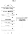
- FIG. 9 is a flowchart illustrating the operation of the compensation circuit according to the second embodiment.
- Processes performed at step S91 and step S92 in FIG. 9 are respectively similar to the processes at step S61 and step S62 in FIG. 6 . Therefore, description of these steps is omitted.
- the compensation circuit 15A determines whether bending of the second actuating beam 170A or 170B is in a stable state or not (step S93).
- the determination method by the bending state determination unit 58 is as described above.
- step S93 If it is determined, at step S93, that the bending state is stable, the compensation circuit 15A, by using the phase shift calculation unit 56A, refers to the temperature retained by the temperature acquisition unit 51, and calculates a compensation amount of timing Popt' using the function Pini(T) (step S94). After performing step S94, the process proceeds to step S98.
- step S93 If it is determined, at step S93, that the bending state is not stable, the process proceeds to step S95.
- steps S95 to S98 in FIG. 9 are respectively similar to the processes at steps S63 to step S66 in FIG. 6 , description of these steps is omitted.
- the above described embodiments can be applicable to various light scanning devices of two-dimensional scan type (raster scan type), such as an eyewear and a projector.
- raster scan type such as an eyewear and a projector.
Landscapes
- Physics & Mathematics (AREA)
- General Physics & Mathematics (AREA)
- Optics & Photonics (AREA)
- Engineering & Computer Science (AREA)
- Computer Hardware Design (AREA)
- Theoretical Computer Science (AREA)
- Mechanical Optical Scanning Systems (AREA)
- Mechanical Light Control Or Optical Switches (AREA)
- Micromachines (AREA)
- Apparatuses For Generation Of Mechanical Vibrations (AREA)
Abstract
Description
- The present invention relates to a light scanning device and a light scanning method.
- Conventionally, there is known a light scanning device that projects an image by scanning laser light in two dimensions on the screen. The light scanning device described above is configured to scan the laser light in two dimensions by driving a MEMS (Micro Electro Mechanical Systems) mirror used for reflecting the laser light, and by sequentially changing the reflection direction.
- When using a relatively-fast resonant actuation to drive the MEMS mirror in a horizontal direction, a phase difference occurs between the drive signal and the displacement of the MEMS mirror. If such phase difference occurs, distortion occurs in a projected image corresponding to the phase difference in the horizontal scanning direction. Therefore, conventionally, a technique has been proposed to eliminate the phase shift in the horizontal scanning direction (refer to
Patent Document 1 for example). - [Patent Document 1] Japanese Unexamined Patent Application Publication No.
2002-365568 - It is known that a phase shift in the horizontal scanning direction occurs depending on variation in bending of a vertical beam for driving (oscillating) a MEMS mirror in a vertical direction, even if temperature is constant. As the variation in the bending is reversible, bending state of the vertical beam reverts to an initial state when the MEMS mirror stops driving. Thus, a phase shift in the horizontal scanning direction occurs even from bending alone.
- However, the effect of the phase shift caused by the bending is not considered in the technique disclosed in the
Patent Document 1. Therefore it is difficult in the conventional technique to improve accuracy of compensation of a phase shift in the horizontal scanning direction. - The present invention is made in light of the above problem, and aims at improving accuracy of compensation of a phase shift in the horizontal scanning direction.
- According to an aspect of the present invention, there is provision for a two-dimensional scan type light scanning device (1) performing oscillation of a mirror (110) in a first direction and a second direction perpendicular to the first direction. The light scanning device includes a second actuating beam (170A, 170B) causing the oscillation of the mirror in the second direction, a differential calculation unit (55) configured to calculate a difference between a bending amount of the second actuating beam (170A, 170B) at a time of an initial drive and a bending amount of the second actuating beam (170A, 170B) after a predetermined period of time, and a phase shift calculation unit (56) configured to calculate an amount of phase shift between a driving signal for oscillating the mirror (110) in the first direction and a signal representing a displacement of the mirror (110) in the first direction, based on the difference.
- It should be noted that reference symbols in the above parentheses are provided in order to facilitate easy understanding and simply represent examples, and the present invention is not limited to aspects illustrated in the drawings.
- According to an aspect of the present invention, it is possible to improve accuracy of compensation of a phase shift in the horizontal scanning direction.
-
-
FIG. 1 is a diagram illustrating a configuration of a light scanning device according to a first embodiment. -
FIG. 2 is a diagram illustrating a light scanning unit according to the first embodiment. -
FIG. 3 is a diagram illustrating a function of a compensation circuit according to the first embodiment. -
FIG. 4 is a graph representing a relation between bending amounts of second actuating beams and temperature according to the first embodiment. -
FIG. 5 is a flowchart illustrating an operation of the compensation circuit according to the first embodiment. -
FIG. 6 is a flowchart illustrating an operation of a phase compensation unit according to the first embodiment. -
FIG. 7 is a diagram illustrating a function of a compensation circuit according to a second embodiment. -
FIG. 8 is a graph representing a relation between a compensation amount of timing and temperature. -
FIG. 9 is a flowchart illustrating an operation of the compensation circuit according to the second embodiment. - In the following, a first embodiment of the present disclosure will be described with reference to the drawings.
FIG. 1 is a diagram illustrating a configuration of a light scanning device according to the first embodiment. - The light scanning device according to the present embodiment includes a light
scanning control unit 10, alight source 20, atemperature sensor 30, and alight scanning unit 40. Details of each component will be described below. - The light
scanning control unit 10 according to the present embodiment controls thelight source 20 and thelight scanning unit 40. The lightscanning control unit 10 includes asystem controller 11, abuffer circuit 12, a mirror driving circuit 13, a laser driving circuit 14, and acompensation circuit 15. - The
system controller 11 provides the mirror driving circuit 13 with a control signal for controlling oscillation of a mirror in thelight scanning unit 40. Thesystem controller 11 also provides the laser driving circuit 14 with a digital image signal. - The
buffer circuit 12 retains data that is output from thelight scanning unit 40. Specifically, thebuffer circuit 12 retains, for example, signals that are output from a vertical oscillating angle sensor and a horizontal oscillating angle sensor included in thelight scanning unit 40. - The mirror driving circuit 13 provides the
light scanning unit 40 with a horizontal driving signal and a vertical driving signal, based on the control signal from thesystem controller 11. The horizontal driving signal is a signal for causing an oscillation of a mirror (described below) in a horizontal direction (first direction), and the vertical driving signal is a signal for causing an oscillation of the mirror in a vertical direction (second direction). - The laser driving circuit 14 provides the
light source 20 with a laser driving signal for driving a laser, based on an image signal from thesystem controller 11. - The
compensation circuit 15 compensates a phase shift in the horizontal scanning direction that is caused by variation in bending of an actuating beam for driving a mirror in a vertical direction. Hereinafter, the horizontal scanning direction may be referred to as a "horizontal direction". The phase shift in the horizontal direction is a phase difference between a horizontal driving signal provided for thelight scanning unit 40 and a horizontal displacement of the mirror (an output signal that is output by the horizontal oscillating angle sensor based on a horizontal displacement of the mirror). Details of thecompensation circuit 15 will be described below. - The
light source 20 according to the present embodiment includes an LD module 21 and adimming filter 22. The LD module 21 includes alaser 21R, alaser 21G, and alaser 21B. - The
lasers system controller 11. Thelaser 21R is, for example, a red semiconductor laser, and emits light with a wavelength λR (e.g., 640 nm). Thelaser 21G is, for example, a green semiconductor laser, and emits light with a wavelength λG (e.g., 530 nm). Thelaser 21B is, for example, a blue semiconductor laser, and emits light with a wavelength λB (e.g., 445 nm). The light beams with respective wavelengths emitted from thelasers dimming filter 22, and the dimmed light enters thelight scanning unit 40. - The
temperature sensor 30 is a sensor used for detecting a temperature of the surroundings of thelight scanning device 1. Thetemperature sensor 30 may be implemented by a thermistor. - The
light scanning unit 40 drives the mirror in the horizontal and the vertical directions in accordance with the horizontal driving signal and the vertical driving signal provided by the mirror driving circuit 13. In accordance with these signals, thelight scanning unit 40 alters a reflecting direction of a laser light, performs scanning using the laser light, and projects images on a screen or the like. - In the following, the
light scanning unit 40 will be further described with reference toFIG. 2. FIG. 2 is a diagram illustrating the light scanning unit according to the first embodiment. - The
light scanning unit 40 according to the present embodiment is, for example, a MEMS (Micro Electro Mechanical Systems) mirror that drives amirror 110 by a piezoelectric element. - The
light scanning unit 40 includes themirror 110, amirror support 120,torsion beams beams first actuating beams movable frame 160,second actuating beams frame 180. Thefirst actuating beams actuation source 151A and anactuation source 151B. Also, thesecond actuating beams actuation sources 171A andactuation sources 171B. A set of thefirst actuating beams second actuating beams mirror 110. -
Slits 122 are formed on themirror support 120 along a circumference of themirror 110. Because theslits 122 are formed, themirror support 120 is reduced in weight, and torsion of thetorsion beams mirror 110. - The
mirror 110 is supported on an upper surface of themirror support 120 in thelight scanning unit 40. Both sides of themirror support 120 are respectively connected to an end portion of thetorsion beam 130A and an end portion of thetorsion beam 130B. Thetorsion beams mirror 110, extend along the axis, and thereby support themirror support 120 from both sides in the axial direction. By torsion of thetorsion beams mirror 110 supported by themirror support 120 oscillates. By the oscillation of themirror 110, themirror 110 performs scanning of laser light emitted on themirror 110. Thetorsion beams beams first actuating beams - The
first actuating beams beams torsion beams mirror support 120, and themirror 110 are supported by themovable frame 160 from outside. One side of the respectivefirst actuating beams movable frame 160. The other side of thefirst actuating beam 150A extends inside, and is connected to the connectingbeams first actuating beam 150B extends inside, and is connected to the connectingbeams - The
first actuating beams torsion beams mirror 110 and themirror support 120 are placed between thefirst actuating beam 150A and thefirst actuating beam 150B. On upper surfaces of thefirst actuating beams actuation source 151A and theactuation source 151B are provided respectively. Theactuation source 151A and theactuation source 151B respectively include an upper electrode formed on a thin film made of a piezoelectric element on an upper surface of thefirst actuating beams actuation source 151A and theactuation source 151B respectively include a lower electrode at a lower surface of the piezoelectric thin film. Thefirst actuating beams - Hence, if different drive voltages having different (inverted) phases are applied to each of the
first actuating beams first actuating beams mirror 110 can oscillate around the axis constructed by thetorsion beams - Hereinafter, the direction in which the
mirror 110 oscillates around the axis constructed by thetorsion beams first actuating beams mirror 110 to oscillate in the horizontal direction (the first direction) by a torsional deformation of thetorsion beams first actuating beams mirror 110 quickly. - At outer circumference of the
movable frame 160, one end of thesecond actuating beam 170A and one end of thesecond actuating beam 170B are connected. Thesecond actuating beams torsion beams movable frame 160 is placed between thesecond actuating beams second actuating beams movable frame 160 from both sides, and cause themovable frame 160 to oscillate around an axis passing through a center of a surface of themirror 110. Thesecond actuating beam 170A is formed of multiple rectangular beams (for example, an even number of rectangular beams) arranged side by side in parallel with thefirst actuating beam 150A. Further, since one end of each rectangular beam is connected (linked) to an end of one of two adjacent rectangular beams, with the other end of the rectangular beam being connected (linked) to an end of the other of the two adjacent rectangular beams, thesecond actuating beam 170A has a zigzag shape as a whole. - The other end of the
second actuating beam 170A is connected to inner circumference of the fixingframe 180. Similarly, thesecond actuating beam 170B is formed of multiple rectangular beams (for example, an even number of rectangular beams) arranged side by side in parallel with thefirst actuating beam 150B. Further, since one end of each rectangular beam is connected (linked) to an end of one of two adjacent rectangular beams, with the other end of the rectangular beam being connected (linked) to an end of the other of the two adjacent rectangular beams, thesecond actuating beam 170B has a zigzag shape as a whole. Further, the other end of thesecond actuating beam 170B is connected to the inner circumference of the fixingframe 180. - On an upper surface of the
second actuating beam 170A, theactuation sources 171A are formed on each rectangular beam (not including curved portions) constituting thesecond actuating beam 170A. Similarly, on an upper surface of thesecond actuating beam 170B, theactuation sources 171B are formed on each rectangular beam constituting thesecond actuating beam 170B. Theactuation source 171A includes an upper electrode on a piezoelectric thin film formed on an upper surface of thesecond actuating beam 170A, astress counter film 8 formed on an upper surface of the piezoelectric thin film, and a lower electrode formed at a lower surface of the piezoelectric thin film. Theactuation source 171B includes an upper electrode on a piezoelectric thin film formed on an upper surface of thesecond actuating beam 170B, astress counter film 8 formed on an upper surface of the piezoelectric thin film, and a lower electrode formed at a lower surface of the piezoelectric thin film. - It should be noted that the
stress counter film 8 is not provided on a region on which a piezoelectric thin film is not formed. The reason is that, if thestress counter film 8 is provided on a region on which a piezoelectric thin film is not formed, stress is applied on the region where stress need not be generated, which would cause deformation or damage of thelight scanning unit 40. - In the present embodiment, in an initial state, the
light scanning unit 40 is configured such that thesecond actuating beams frame 180, by thestress counter film 8 applying compressive stress to thesecond actuating beams FIG. 2 for example. Note that the compressive stress is stress to bend thesecond actuating beams frame 180. Further, the initial state means a state that driving signals are not supplied to thelight scanning unit 40. - As the
second actuating beams light scanning unit 40 illustrated inFIG. 2 , if thesecond actuating beams second actuating beams light scanning unit 40 can reduce occurrence of damage or fatigue of material, as compared to a light scanning unit not having bending in thesecond actuating beams - Note that the
second actuating beams second actuating beams actuation sources mirror 110 is not moving. - To each of the rectangular beams in the
second actuating beams second actuating beams movable frame 160. - Because the
second actuating beams second actuating beams mirror 110 to oscillate in a vertical direction (note that a direction perpendicular to the horizontal direction (mentioned above) is referred to as the "vertical direction"). That is, thesecond actuating beams mirror 110 to oscillate in the vertical direction. In other words, thesecond actuating beams mirror 110 to oscillate in the vertical direction (second direction) through their bending deformation. For example, non-resonant vibration mode may be used for the vertical actuation of thesecond actuating beams - Suppose that the
actuation sources 171A include actuation sources 171A1, 171A2, 171A3, 171A4, 171A5, and 171A6, which are aligned on the right side of themovable frame 160. Similarly, suppose that theactuation sources 171B include actuation sources 171B1, 171B2, 171B3, 171B4, 171B5, and 171B6, which are aligned on the left side of themovable frame 160. If the actuation sources 171A1, 171B1, 171A3, 171B3, 171A5, and 171B5 are driven by applying voltage having the same waveform, and if the actuation sources 171A2, 171B2, 171A4, 171B4, 171A6, 171B6 are driven by applying voltage having different waveform from that applied to the actuation sources 171A1 and the like, themirror 110 oscillates in a vertical direction. - Drive wiring for applying a drive voltage to the upper electrode and the lower electrode of the
actuation source 151A is connected to a predetermined terminal which is one ofterminals 190A provided on the fixingframe 180. Also, drive wiring for applying a drive voltage to the upper electrode and the lower electrode of theactuation source 151B is connected to a predetermined terminal which is one ofterminals 190B provided on the fixingframe 180. Drive wiring for applying a drive voltage to the upper electrode and the lower electrode of theactuation source 171A is connected to a predetermined terminal which is one of theterminals 190A provided on the fixingframe 180. Also, drive wiring for applying a drive voltage to the upper electrode and the lower electrode of theactuation source 171B is connected to a predetermined terminal which is one of theterminals 190B provided on the fixingframe 180. - The
light scanning unit 40 also includespiezoelectric sensors mirror 110 while themirror 110 is oscillating in the horizontal direction by a drive voltage applied to theactuation sources piezoelectric sensor 191 is provided on the connectingbeam 140A, and thepiezoelectric sensor 192 is provided on the connectingbeam 140B. - Further, the
light scanning unit 40 also includespiezoelectric sensors mirror 110 while themirror 110 is oscillating in the vertical direction by a drive voltage applied to theactuation sources piezoelectric sensor 195 is provided on one of the rectangular beams included in thesecond actuating beam 170A, and thepiezoelectric sensor 196 is provided on one of the rectangular beams included in thesecond actuating beam 170B. - The
piezoelectric sensor 191 outputs a voltage corresponding to a displacement of the connectingbeam 140A which is caused by a horizontal incline of themirror 110 transmitted via thetorsion beam 130A. Thepiezoelectric sensor 192 outputs a voltage corresponding to a displacement of the connectingbeam 140B which is caused by a horizontal incline of themirror 110 transmitted via thetorsion beam 130B. Thepiezoelectric sensor 195 outputs a voltage corresponding to a displacement of one of the rectangular beams included in thesecond actuating beam 170A on which thepiezoelectric sensor 195 is provided, which is caused by a vertical incline of themirror 110. Thepiezoelectric sensor 196 outputs a voltage corresponding to a displacement of one of the rectangular beams included in thesecond actuating beam 170B on which thepiezoelectric sensor 196 is provided, which is caused by a vertical incline of themirror 110. - In the present embodiment, a vertical incline of the
mirror 110 is detected using outputs of thepiezoelectric sensors piezoelectric sensors buffer circuit 12. Note that only one voltage information output by one of thepiezoelectric sensors buffer circuit 12. - In the present embodiment, the
compensation circuit 15 compensates for emission timing of the laser light from thelight source 20, based on the voltage information retained in thebuffer circuit 12. - Each of the
piezoelectric sensors - Sensor wires drawn from the upper electrode and the lower electrode of the
piezoelectric sensor 191 are connected to a predetermined terminal which is one of theterminals 190B provided on the fixingframe 180. Sensor wires drawn from the upper electrode and the lower electrode of thepiezoelectric sensor 195 are connected to a predetermined terminal which is one of theterminals 190A provided on the fixingframe 180. Sensor wires drawn from the upper electrode and the lower electrode of thepiezoelectric sensor 192 are connected to a predetermined terminal which is one of theterminals 190B provided on the fixingframe 180. Sensor wires drawn from the upper electrode and the lower electrode of thepiezoelectric sensor 196 are connected to a predetermined terminal which is one of theterminals 190B provided on the fixingframe 180. - Next, a function of the
compensation circuit 15 will be described with reference toFIG. 3. FIG. 3 is a diagram illustrating the function of the compensation circuit according to the first embodiment. - The
compensation circuit 15 according to the present embodiment includes atemperature acquisition unit 51 and aphase compensation unit 52. Thetemperature acquisition unit 51 according to the present embodiment acquires temperature detected by thetemperature sensor 30. - The
phase compensation unit 52 includes acoefficient storage unit 53, a sensoroutput acquisition unit 54, adifferential calculation unit 55, a phaseshift calculation unit 56, and atiming compensation unit 57. - The
coefficient storage unit 53 stores coefficients of a formula defining a function representing a relation between bending amounts of thesecond actuating beam coefficient storage unit 53 also stores coefficients of a formula defining a function representing a relation between variation of bending amounts and an amount of phase shift in the horizontal direction. Details of the function represented by the coefficients stored in thecoefficient storage unit 53 will be described below. - The sensor
output acquisition unit 54 obtains voltage information retained in thebuffer circuit 12. The voltage information retained in thebuffer circuit 12 is output signals from thepiezoelectric sensors - The
differential calculation unit 55 calculates a difference between a bending amount of thesecond actuating beam second actuating beam temperature acquisition unit 51, the function defined by the coefficients stored in thecoefficient storage unit 53, and the output signals acquired by the sensoroutput acquisition unit 54. The current bending amount of thesecond actuating beam second actuating beam second actuating beam second actuating beam piezoelectric sensors - The phase
shift calculation unit 56 calculates an amount of phase shift in the horizontal direction, based on the difference calculated by thedifferential calculation unit 55, and the coefficients stored in thecoefficient storage unit 53. The amount of phase shift in the horizontal direction corresponds to a compensation amount of timing of emitting laser light. - The
timing compensation unit 57 compensates timing of emitting the laser light based on the compensation amount of the timing. Specifically, thetiming compensation unit 57 sends the compensation amount of the timing to thesystem controller 11, to update (modify) a timing to emit the laser light. - In the following, the coefficients stored in the
coefficient storage unit 53 will be explained with reference toFIG. 4 . -
FIG. 4 is a graph representing a relation between bending amounts of the second actuating beams and temperature according to the first embodiment. - In the graph illustrated in
FIG. 4 , a horizontal axis represents temperature. And, a vertical axis represents a bending amount of thesecond actuating beam piezoelectric sensors second actuating beam second actuating beams FIG. 4 is represented by an output signal of thepiezoelectric sensor 195. - In
FIG. 4 , a curved line L1 represents a graph of a function Vinit(T) representing a relation between a bending amount (Vinit) and temperature T at a time of an initial drive of thelight scanning unit 40. The time of the initial drive is a time when supply of a driving signal to thelight scanning unit 40 is started. - Additionally, in
FIG. 4 , a curved line L2 is a graph of a function Vsen(T) representing a relation between a bending amount (Vsen) and temperature T at a time when a predetermined period of time elapses after thelight scanning unit 40 has started driving. The bending amount (Vsen) is a value (voltage) of the output signal obtained from thepiezoelectric sensor 195 used as the vertical oscillating angle sensor. - As can be seen from this graph, in the present embodiment, even if temperature is constant, output signal value of the
piezoelectric sensor 195 varies as time passes. This variation causes a phase shift in the horizontal direction. Therefore, in the present embodiment, a difference α is calculated between the bending amount at a time of an initial drive with respect to the temperature T obtained by thetemperature acquisition unit 51 and the bending amount when a certain period elapses after the time of the initial drive with respect to the temperature T, and based on the difference α, a phase shift in the horizontal direction is calculated. - The function Vinit(T) is expressed by a formula (1) described below. Coefficients a, b, and c are recorded in the
coefficient storage unit 53 in advance.
- Note that the function Vinit(T) may be obtained by measuring output signals of the
piezoelectric sensor 195 in advance. Specifically, output signals of thepiezoelectric sensor 195 at the time of the initial drive of thelight scanning unit 40 in a case in which a phase shift in the horizontal direction is zero may be measured by varying temperature T. In the present embodiment, a coefficient β for converting the difference α into an amount of phase shift (in the horizontal direction) is also obtained in advance, and the coefficient β is also stored in thecoefficient storage unit 53. - The case in which a phase shift in the horizontal direction is zero means a state in which a phase difference between a horizontal driving signal provided for the
light scanning unit 40 and an output signal that is output by the horizontal oscillating angle sensor based on a horizontal displacement of the mirror becomes constant. - Next, an operation of the
compensation circuit 15 according to the present embodiment will be described with reference toFIG. 5. FIG. 5 is a flowchart illustrating the operation of the compensation circuit according to the first embodiment. - The
compensation circuit 15 according to the present embodiment first checks whether the power of thelight scanning device 1 is turned on or not (step S51). If it is determined that the power is off, thecompensation circuit 15 terminates the process. - If it is determined that the power is on at step S51, the
compensation circuit 15 determines whether a temperature measurement interval has elapsed or not by using the temperature acquisition unit 51 (step S52). The temperature measurement interval may be stored in thetemperature acquisition unit 51. When the temperature measurement interval has not elapsed at step S52, thecompensation circuit 15 waits until the temperature measurement interval elapses. - When the temperature measurement interval has elapsed at step S52, the
temperature acquisition unit 51 acquires temperature detected by thetemperature sensor 30, and retains the temperature (step S53). - Next, the
temperature acquisition unit 51 determines whether a phase compensation interval has elapsed or not by using the phase compensation unit 52 (step S54). The phase compensation interval may be stored in thephase compensation unit 52. It is preferable that the phase compensation interval is longer than the temperature measurement interval. - When the phase compensation interval has not elapsed at step S54, the
compensation circuit 15 waits until the phase compensation interval elapses. - When the phase compensation interval has elapsed at step S54, the
temperature acquisition unit 51 performs a process for compensating the phase shift in the horizontal direction by using the phase compensation unit 52 (step S55). After step S55, the process reverts to step S51. - As described above, in the present embodiment, each of the process for acquiring temperature by the
temperature acquisition unit 51 and the process for compensating the phase shift by thephase compensation unit 52 is executed independently. Accordingly, in the present embodiment, temperature can be obtained by thetemperature acquisition unit 51 at a desired time. For example, thetemperature acquisition unit 51 can acquire temperature in synchronization with a process other than a process by thephase compensation unit 52. Therefore in the present embodiment, for example, the acquisition of temperature can be performed more frequently than the process performed by thephase compensation unit 52, only by setting the temperature measurement interval smaller than the phase compensation interval, and thereby to avoid increasing workload of thecompensation circuit 15. - Next, an operation of the
phase compensation unit 52 according to the present embodiment will be described with reference toFIG. 6. FIG. 6 is a flowchart illustrating the operation of the phase compensation unit according to the first embodiment. - The
phase compensation unit 52 according to the present embodiment acquires, by the sensoroutput acquisition unit 54, an output signal retained in the buffer circuit 12 (step S61). Next, by using thedifferential calculation unit 55, thephase compensation unit 52 refers to the temperature retained by the temperature acquisition unit 51 (step S62). - Next, the
differential calculation unit 55 calculates a bending amount of thesecond actuating beam 170A at a time of an initial drive, using the function Vinit(T) represented by the coefficients stored in thecoefficient storage unit 53, and the temperature T that was referred to at step S62. Subsequently, thedifferential calculation unit 55 calculates the difference α between the bending amount of thesecond actuating beam 170A at the time of the initial drive and the output signal (bending amount) acquired by the sensoroutput acquisition unit 54 at step S61 (step S63). Note that difference α at temperature of T is calculated based on a following formula (2). Vsen(T) in the formula (2) represents an output signal of thepiezoelectric sensor 195 at temperature of T.
- Next, the
compensation circuit 15 calculates a phase shift in the horizontal direction caused by the difference α, by using the phase shift calculation unit 56 (step S64). In the following, the phase shift amount caused by the difference α is denoted as "Pcomp". The phaseshift calculation unit 56 calculates the phase shift amount "Pcomp" using a following formula (3). In the present embodiment, the difference α is converted to a phase shift amount caused by the difference α, based on the formula (3).
- Next, the phase
shift calculation unit 56 calculates a compensation amount of timing based on the phase shift amount "Pcomp" (step S65). The phaseshift calculation unit 56 calculates the compensation amount of timing using a following formula (4). Note that, in the formula (4), the compensation amount of timing is denoted as "Popt" and a phase shift amount at a time of an initial drive is denoted as "Pini".
- Next, by using the
timing compensation unit 57, thecompensation circuit 15 updates (modifies) the timing to emit laser light by thesystem controller 11, based on the compensation amount of timing (step S66), and terminates the process. The update may be performed, for example, by delaying the timing to emit laser light by the time Popt [sec]. - As described above, in the present embodiment, a phase difference between a horizontal driving signal and an output signal of the
piezoelectric sensor second actuating beam - Also in the present embodiment, a phase difference in the horizontal direction can be compensated by a simple configuration, without adding a dedicated sensor or the like for compensation of phase difference.
- Therefore, in the present embodiment, image quality degradation caused by phase difference in the horizontal direction, such as a double vision of a projected image, can be reduced.
- In the following, a second embodiment will be described. The second embodiment differs from the first embodiment in the following point. A light scanning device according to the second embodiment checks whether bending of an actuating beam for oscillating a mirror in a vertical direction is in a stable state or not. If the bending is in a stable state, the light scanning device performs compensation without using a difference of a bending amount that was used in the first embodiment. In the following description concerning the second embodiment, the difference from the first embodiment is mainly explained. Further, with respect to the elements having similar functions or configurations, the same symbols are attached and the explanation about such elements is omitted.
-
FIG. 7 is a diagram illustrating the function of a compensation circuit according to the second embodiment. Acompensation circuit 15A according to the present embodiment includes thetemperature acquisition unit 51 and aphase compensation unit 52A. - The
phase compensation unit 52A according to the present embodiment includes acoefficient storage unit 53A, the sensoroutput acquisition unit 54, thedifferential calculation unit 55, a phaseshift calculation unit 56A, thetiming compensation unit 57, and a bendingstate determination unit 58. - In addition to coefficients a, b, c, and β, the
coefficient storage unit 53A according to the present embodiment retains coefficients e, f, and g, which are coefficients of a formula defining a function representing a relation between a compensation amount of timing Popt and temperature T. Details of the coefficients e, f, and g will be described below. - When it is determined by the bending
state determination unit 58 that bending of thesecond actuating beam shift calculation unit 56A according to the present embodiment calculates a compensation amount of timing Popt by referring to a function (formula (5)) represented by the coefficients e, f, and g. - The bending
state determination unit 58 determines whether the bending of thesecond actuating beam piezoelectric sensor 195 acquired by the sensoroutput acquisition unit 54 is equal to the value obtained most recently (previously), the bendingstate determination unit 58 determines that the state of the bending is stable. - However, a way of determination performed by the bending
state determination unit 58 is not limited to the way described above. For example, the bendingstate determination unit 58 may determine that the state of the bending is stable, when a difference between the output signal value (voltage) of thepiezoelectric sensor 195 acquired by the sensoroutput acquisition unit 54 and output signal value (voltage) of thepiezoelectric sensor 195 at a time of an initial drive becomes consistent for a continuous number of times. - In the following, a relation between a compensation amount of timing P and temperature T will be described with reference to
FIG. 8. FIG. 8 is a graph representing a relation between a compensation amount of timing and temperature. In the graph illustrated inFIG. 8 , a vertical axis represents a compensation amount of timing, and a horizontal axis represents temperature. - A curved line L3 illustrated in
FIG. 8 is a graph of a function Pini(T) representing a relation between a compensation amount of timing, at a time of an initial drive of thelight scanning unit 40, and temperature T. The function Pini(T) is expressed by a formula (5) described below.
- Note that the function Pini(T) may be obtained by measuring/calculating compensation amounts of timing in advance. Specifically, after operating the
light scanning unit 40 continuously for a certain period of time to attain a state in which bending of thesecond actuating beam coefficient storage unit 53A. - Next, an operation of the
compensation circuit 15A according to the present embodiment will be described with reference toFIG. 9. FIG. 9 is a flowchart illustrating the operation of the compensation circuit according to the second embodiment. - Processes performed at step S91 and step S92 in
FIG. 9 are respectively similar to the processes at step S61 and step S62 inFIG. 6 . Therefore, description of these steps is omitted. - Next, by using the bending
state determination unit 58, thecompensation circuit 15A determines whether bending of thesecond actuating beam state determination unit 58 is as described above. - If it is determined, at step S93, that the bending state is stable, the
compensation circuit 15A, by using the phaseshift calculation unit 56A, refers to the temperature retained by thetemperature acquisition unit 51, and calculates a compensation amount of timing Popt' using the function Pini(T) (step S94). After performing step S94, the process proceeds to step S98. - If it is determined, at step S93, that the bending state is not stable, the process proceeds to step S95.
- As processes performed at steps S95 to S98 in
FIG. 9 are respectively similar to the processes at steps S63 to step S66 inFIG. 6 , description of these steps is omitted. - As described above, in the present embodiment, when the bending state is stable, a compensation amount of timing corresponding to temperature can be calculated directly using the function Pini(T). Therefore, a processing workload of the light scanning device can be reduced.
- Further, the above described embodiments can be applicable to various light scanning devices of two-dimensional scan type (raster scan type), such as an eyewear and a projector.
- Although the present invention has been described with reference to embodiments, the present invention is not limited to these embodiments. Various variations may be made without departing from the scope of the invention, and the variations can be appropriately determined according to application form.
- The present application is based on and claims the benefit of priority of Japanese Patent Applications No.
2017-025374 filed on February 14, 2017
Claims (11)
- A two-dimensional scan type light scanning device performing oscillation of a mirror in a first direction and a second direction perpendicular to the first direction, the light scanning device comprising:a second actuating beam causing the oscillation of the mirror in the second direction;a differential calculation unit configured to calculate a difference between a bending amount of the second actuating beam at a time of an initial drive and a bending amount of the second actuating beam after a predetermined period of time; anda phase shift calculation unit configured to calculate an amount of phase shift between a driving signal for oscillating the mirror in the first direction and a signal representing a displacement of the mirror in the first direction, based on the difference.
- The light scanning device according to claim 1, further comprising an oscillating angle sensor configured to detect an oscillating angle of the mirror in the second direction, the bending amount being identified based on an output signal obtained from the oscillating angle sensor.
- The light scanning device according to claim 1 or 2, the phase shift calculation unit being configured to convert the difference into the amount of phase shift by multiplying the difference by a predetermined coefficient.
- The light scanning device according to any one of claims 1 to 3, further comprising a temperature detecting unit, and a coefficient storage unit retaining a first function representing a relation between a temperature and the bending amount of the second actuating beam at the time of the initial drive, wherein the differential calculation unit is configured to, based on the temperature detected by the temperature detecting unit and the first function, calculate the difference at the detected temperature.
- The light scanning device according to claim 4, further comprising a bending state determination unit configured to determine whether a state of bending of the second actuating beam is stable or not, the coefficient storage unit further retaining a second function representing a relation between the temperature and the amount of phase shift,
wherein, in response to a determination that the state of the bending of the second actuating beam is stable, the phase shift calculation unit is configured to calculate the difference based on the temperature detected by the temperature detecting unit and the second function. - The light scanning device according to any one of claims 1 to 5, further comprising:a light source configured to emit laser light to the mirror; anda timing compensation unit configured to modify timing for emitting the laser light by the light source, based on the amount of phase shift.
- The light scanning device according to claim 1, further comprising a first actuating beam causing the oscillation of the mirror in the first direction,
the mirror being configured to oscillate in the first direction by a torsional deformation of the first actuating beam, and to oscillate in the second direction by a bending deformation of the second actuating beam. - The light scanning device according to claim 7,
wherein the second actuating beam is formed of multiple rectangular beams arranged side by side in parallel with the first actuating beam,
the second actuating beam has a zigzag shape as a whole, by both ends of each of the rectangular beams being respectively linked to an end of different adjacent rectangular beams, and
the mirror is oscillated by a bending deformation of each of the rectangular beams. - The light scanning device according to claim 8, further comprising a fixing frame, the mirror being configured to oscillate inside the fixing frame,
wherein the second actuating beam bends downward relative to the fixing frame at the time of the initial drive. - A light scanning method of a two-dimensional scan type light scanning device performing oscillation of a mirror in a first direction and a second direction perpendicular to the first direction, the light scanning device including a second actuating beam causing the oscillation of the mirror in the second direction, the method comprising:calculating a difference between a bending amount of the second actuating beam at a time of an initial drive and a bending amount of the second actuating beam after a predetermined period of time; andcalculating an amount of phase shift between a driving signal for oscillating the mirror in the first direction and a signal representing a displacement of the mirror in the first direction, based on the difference.
- The light scanning method according to claim 10, the light scanning device further comprising a first actuating beam causing the oscillation of the mirror in the first direction,
the mirror being configured to oscillate in the first direction by a torsional deformation of the first actuating beam, and to oscillate in the second direction by a bending deformation of the second actuating beam.
Applications Claiming Priority (1)
| Application Number | Priority Date | Filing Date | Title |
|---|---|---|---|
| JP2017025374A JP6908825B2 (en) | 2017-02-14 | 2017-02-14 | Optical scanning device and optical scanning method |
Publications (1)
| Publication Number | Publication Date |
|---|---|
| EP3367157A1 true EP3367157A1 (en) | 2018-08-29 |
Family
ID=61192718
Family Applications (1)
| Application Number | Title | Priority Date | Filing Date |
|---|---|---|---|
| EP18155981.6A Withdrawn EP3367157A1 (en) | 2017-02-14 | 2018-02-09 | Light scanning device and light scanning method |
Country Status (4)
| Country | Link |
|---|---|
| US (1) | US10451867B2 (en) |
| EP (1) | EP3367157A1 (en) |
| JP (1) | JP6908825B2 (en) |
| CN (1) | CN108427190B (en) |
Cited By (1)
| Publication number | Priority date | Publication date | Assignee | Title |
|---|---|---|---|---|
| US20180231767A1 (en) * | 2017-02-14 | 2018-08-16 | Mitsumi Electric Co., Ltd. | Light scanning device and light scanning method |
Families Citing this family (6)
| Publication number | Priority date | Publication date | Assignee | Title |
|---|---|---|---|---|
| JP2019164180A (en) * | 2018-03-19 | 2019-09-26 | 株式会社リコー | Optical scanner, image display device, head-up display, and movable body |
| CN111338387B (en) * | 2018-12-18 | 2023-05-26 | 上海乂义实业有限公司 | Micro-scanning super-resolution control system and method based on piezoelectric driving |
| JP7157332B2 (en) * | 2018-12-28 | 2022-10-20 | ミツミ電機株式会社 | Optical scanning device and its control method |
| US10939080B2 (en) * | 2019-03-29 | 2021-03-02 | Facebook Technologies, Llc | Trajectory estimation for a MEMS reflector |
| JP7343410B2 (en) * | 2020-01-23 | 2023-09-12 | スタンレー電気株式会社 | Optical deflector, how to control the optical deflector |
| CN113568162A (en) * | 2021-07-20 | 2021-10-29 | 绍兴中芯集成电路制造股份有限公司 | Self-compensating micro-mirror driving device and compensation method of working voltage thereof |
Citations (5)
| Publication number | Priority date | Publication date | Assignee | Title |
|---|---|---|---|---|
| JP2002365568A (en) | 2001-06-04 | 2002-12-18 | Canon Inc | Two-dimensional light scanning device and drive method of the two-dimensional light scanning device |
| WO2007146093A2 (en) * | 2006-06-06 | 2007-12-21 | Microvision, Inc. | Beam scanner with reduced phase error |
| US20090153933A1 (en) * | 2007-12-13 | 2009-06-18 | Satoshi Tsuchiya | Optical scanning device and image forming apparatus |
| EP2781949A1 (en) * | 2013-03-18 | 2014-09-24 | Seiko Epson Corporation | Optical scanner, image display apparatus, and head mounted display |
| WO2016194514A1 (en) * | 2015-05-29 | 2016-12-08 | ミツミ電機株式会社 | Optical scanning device, method for manufacturing same, and optical scanning control device |
Family Cites Families (15)
| Publication number | Priority date | Publication date | Assignee | Title |
|---|---|---|---|---|
| JP5114178B2 (en) * | 2007-12-13 | 2013-01-09 | 株式会社リコー | Method for adjusting optical scanning device |
| JP5458837B2 (en) * | 2009-03-16 | 2014-04-02 | 株式会社リコー | Optical scanning device |
| WO2010124229A2 (en) * | 2009-04-24 | 2010-10-28 | National Semiconductor Corporation | Method and system for providing resonant frequency change compensation in a drive signal for a mems scanner |
| JP5829391B2 (en) * | 2010-09-22 | 2015-12-09 | 日本信号株式会社 | Optical scanning device and optical distance measuring device using the same |
| JP2012145910A (en) * | 2010-12-24 | 2012-08-02 | Mitsumi Electric Co Ltd | Structure |
| JP2013171226A (en) * | 2012-02-22 | 2013-09-02 | Funai Electric Co Ltd | Image display device and mirror driving method of the same |
| WO2014068846A1 (en) * | 2012-10-31 | 2014-05-08 | パナソニック株式会社 | Actuator |
| JP6123290B2 (en) * | 2012-12-26 | 2017-05-10 | 株式会社リコー | Piezoelectric actuator device, two-dimensional scanning device, image forming device, and image projection device |
| JP6149516B2 (en) * | 2013-06-03 | 2017-06-21 | ミツミ電機株式会社 | Optical scanning device, optical scanning control device, and optical scanning unit |
| JP6382297B2 (en) * | 2014-02-21 | 2018-08-29 | オリンパス株式会社 | Method for calculating scanning trajectory of light and optical scanning device |
| JP6324817B2 (en) * | 2014-06-03 | 2018-05-16 | スタンレー電気株式会社 | Optical scanner and optical deflector control method |
| WO2016111818A1 (en) * | 2015-01-05 | 2016-07-14 | Avery Dennison Corporation | Inherently printable polymeric and related methods |
| JP6516516B2 (en) * | 2015-03-16 | 2019-05-22 | スタンレー電気株式会社 | Light deflector |
| JP6623584B2 (en) * | 2015-07-07 | 2019-12-25 | 日本精機株式会社 | Image generation device, head-up display |
| JP6908825B2 (en) * | 2017-02-14 | 2021-07-28 | ミツミ電機株式会社 | Optical scanning device and optical scanning method |
-
2017
- 2017-02-14 JP JP2017025374A patent/JP6908825B2/en active Active
-
2018
- 2018-02-07 US US15/890,688 patent/US10451867B2/en active Active
- 2018-02-09 EP EP18155981.6A patent/EP3367157A1/en not_active Withdrawn
- 2018-02-11 CN CN201810140785.0A patent/CN108427190B/en active Active
Patent Citations (5)
| Publication number | Priority date | Publication date | Assignee | Title |
|---|---|---|---|---|
| JP2002365568A (en) | 2001-06-04 | 2002-12-18 | Canon Inc | Two-dimensional light scanning device and drive method of the two-dimensional light scanning device |
| WO2007146093A2 (en) * | 2006-06-06 | 2007-12-21 | Microvision, Inc. | Beam scanner with reduced phase error |
| US20090153933A1 (en) * | 2007-12-13 | 2009-06-18 | Satoshi Tsuchiya | Optical scanning device and image forming apparatus |
| EP2781949A1 (en) * | 2013-03-18 | 2014-09-24 | Seiko Epson Corporation | Optical scanner, image display apparatus, and head mounted display |
| WO2016194514A1 (en) * | 2015-05-29 | 2016-12-08 | ミツミ電機株式会社 | Optical scanning device, method for manufacturing same, and optical scanning control device |
Cited By (2)
| Publication number | Priority date | Publication date | Assignee | Title |
|---|---|---|---|---|
| US20180231767A1 (en) * | 2017-02-14 | 2018-08-16 | Mitsumi Electric Co., Ltd. | Light scanning device and light scanning method |
| US10451867B2 (en) * | 2017-02-14 | 2019-10-22 | Mitsumi Electric Co., Ltd. | Light scanning device and light scanning method |
Also Published As
| Publication number | Publication date |
|---|---|
| US20180231767A1 (en) | 2018-08-16 |
| JP6908825B2 (en) | 2021-07-28 |
| CN108427190A (en) | 2018-08-21 |
| US10451867B2 (en) | 2019-10-22 |
| JP2018132611A (en) | 2018-08-23 |
| CN108427190B (en) | 2021-11-09 |
Similar Documents
| Publication | Publication Date | Title |
|---|---|---|
| EP3367157A1 (en) | Light scanning device and light scanning method | |
| US9291817B2 (en) | Optical deflection device, apparatus including the same, and method of controlling optical deflecting device | |
| JP6201528B2 (en) | Optical deflection apparatus, image forming apparatus, head-up display, and vehicle | |
| JP4929738B2 (en) | Optical scanning device, optical scanning device control method, and image display device | |
| EP2962984B1 (en) | Optical deflection apparatus, image forming apparatus, image display apparatus, moving body apparatus, and adjusting method of optical deflection apparatus | |
| JP6891402B2 (en) | Adjustment method of light deflector, image forming device, image display device, object device, and light deflector | |
| EP3392698B1 (en) | Light deflection apparatus, head-up display apparatus, optical writing unit, image forming apparatus, and object recognition apparatus | |
| EP3349441A2 (en) | Image projection apparatus and compensation method | |
| CN112352185B (en) | Adjusting the resonant frequency of a scanning mirror | |
| WO2014103462A1 (en) | Image display device, and image display method and program | |
| JP2018010100A (en) | Laser projection display device | |
| JP2023015199A (en) | Scanner and distance measuring device | |
| JP6754074B2 (en) | Optical scanning controller | |
| US20100085618A1 (en) | Oscillator device, optical deflecting device and method of controlling the same | |
| KR100905553B1 (en) | Mirror location compensating apparatus and method thereof | |
| JP2006350344A (en) | Apparatus for measuring position of mirror of diffractive light modulator and performing positional compensation and method of controlling the same | |
| JP4389740B2 (en) | Vibrating body control device, image forming apparatus including the same, and swinging scanner control method | |
| JP2007025191A (en) | Image display device and method for controlling the image display device | |
| JP7057534B2 (en) | Optical scanning device and optical scanning method | |
| US11169372B2 (en) | Light scanning apparatus and method for controlling light scanning apparatus | |
| EP3473004B1 (en) | Control device, image projection apparatus, and control method | |
| JP2020101589A (en) | Optical deflector, image projection device, laser head lamp, and movable body | |
| JP2015040928A (en) | Optical deflector, image forming apparatus, vehicle, and method of controlling optical deflector | |
| US11327296B2 (en) | Light deflector, image projection apparatus, vehicle, and adjusting method | |
| US10453370B1 (en) | Control apparatus, optical scanning apparatus, display apparatus, and control method |
Legal Events
| Date | Code | Title | Description |
|---|---|---|---|
| PUAI | Public reference made under article 153(3) epc to a published international application that has entered the european phase |
Free format text: ORIGINAL CODE: 0009012 |
|
| STAA | Information on the status of an ep patent application or granted ep patent |
Free format text: STATUS: THE APPLICATION HAS BEEN PUBLISHED |
|
| AK | Designated contracting states |
Kind code of ref document: A1 Designated state(s): AL AT BE BG CH CY CZ DE DK EE ES FI FR GB GR HR HU IE IS IT LI LT LU LV MC MK MT NL NO PL PT RO RS SE SI SK SM TR |
|
| AX | Request for extension of the european patent |
Extension state: BA ME |
|
| STAA | Information on the status of an ep patent application or granted ep patent |
Free format text: STATUS: REQUEST FOR EXAMINATION WAS MADE |
|
| 17P | Request for examination filed |
Effective date: 20190108 |
|
| RBV | Designated contracting states (corrected) |
Designated state(s): AL AT BE BG CH CY CZ DE DK EE ES FI FR GB GR HR HU IE IS IT LI LT LU LV MC MK MT NL NO PL PT RO RS SE SI SK SM TR |
|
| STAA | Information on the status of an ep patent application or granted ep patent |
Free format text: STATUS: REQUEST FOR EXAMINATION WAS MADE |
|
| STAA | Information on the status of an ep patent application or granted ep patent |
Free format text: STATUS: EXAMINATION IS IN PROGRESS |
|
| STAA | Information on the status of an ep patent application or granted ep patent |
Free format text: STATUS: EXAMINATION IS IN PROGRESS |
|
| 17Q | First examination report despatched |
Effective date: 20211006 |
|
| STAA | Information on the status of an ep patent application or granted ep patent |
Free format text: STATUS: THE APPLICATION HAS BEEN WITHDRAWN |
|
| 18W | Application withdrawn |
Effective date: 20220121 |