EP3367156A1 - Wavelength variable interference filter and optical module - Google Patents
Wavelength variable interference filter and optical module Download PDFInfo
- Publication number
- EP3367156A1 EP3367156A1 EP18158844.3A EP18158844A EP3367156A1 EP 3367156 A1 EP3367156 A1 EP 3367156A1 EP 18158844 A EP18158844 A EP 18158844A EP 3367156 A1 EP3367156 A1 EP 3367156A1
- Authority
- EP
- European Patent Office
- Prior art keywords
- holding portion
- short
- long
- movable
- side holding
- Prior art date
- Legal status (The legal status is an assumption and is not a legal conclusion. Google has not performed a legal analysis and makes no representation as to the accuracy of the status listed.)
- Granted
Links
Images




Classifications
-
- G—PHYSICS
- G02—OPTICS
- G02B—OPTICAL ELEMENTS, SYSTEMS OR APPARATUS
- G02B26/00—Optical devices or arrangements for the control of light using movable or deformable optical elements
- G02B26/001—Optical devices or arrangements for the control of light using movable or deformable optical elements based on interference in an adjustable optical cavity
-
- G—PHYSICS
- G01—MEASURING; TESTING
- G01J—MEASUREMENT OF INTENSITY, VELOCITY, SPECTRAL CONTENT, POLARISATION, PHASE OR PULSE CHARACTERISTICS OF INFRARED, VISIBLE OR ULTRAVIOLET LIGHT; COLORIMETRY; RADIATION PYROMETRY
- G01J3/00—Spectrometry; Spectrophotometry; Monochromators; Measuring colours
- G01J3/12—Generating the spectrum; Monochromators
- G01J3/26—Generating the spectrum; Monochromators using multiple reflection, e.g. Fabry-Perot interferometer, variable interference filters
-
- G—PHYSICS
- G02—OPTICS
- G02B—OPTICAL ELEMENTS, SYSTEMS OR APPARATUS
- G02B5/00—Optical elements other than lenses
- G02B5/20—Filters
- G02B5/26—Reflecting filters
-
- G—PHYSICS
- G02—OPTICS
- G02B—OPTICAL ELEMENTS, SYSTEMS OR APPARATUS
- G02B5/00—Optical elements other than lenses
- G02B5/20—Filters
- G02B5/28—Interference filters
-
- G—PHYSICS
- G02—OPTICS
- G02B—OPTICAL ELEMENTS, SYSTEMS OR APPARATUS
- G02B5/00—Optical elements other than lenses
- G02B5/20—Filters
- G02B5/28—Interference filters
- G02B5/284—Interference filters of etalon type comprising a resonant cavity other than a thin solid film, e.g. gas, air, solid plates
Definitions
- the present invention relates to a wavelength variable interference filter and an optical module.
- a movable portion on which the reflection film is installed and a holding portion which surrounds the outer circumference of the movable portion and holds the movable portion so that the movable portion is displaceable are formed in a substrate.
- a gap amount between a pair of reflection films is changed.
- the wavelength variable interference filter can be combined for use with a light receiving sensor that receives light transmitted through the wavelength variable interference filter. Therefore, when a light receiving surface of the light receiving sensor is rectangular or square, the planar shapes of the reflection film and the movable portion are also rectangular or square. However, when the movable portion is rectangular or square, the following problem occurs.
- a displacement amount of a central position is larger than a displacement amount of a periphery position.
- Defining a difference of the magnitude of displacement amounts as a bending amount when rigidity of the holding portion is uniform, the bending amount of the movable portion in a longer side direction is larger than the bending amount of the movable portion in a shorter side direction. Therefore, the gap amount is irregular in the plane of the reflection film.
- the movable portion When the movable portion is rectangular or square, it is more difficult for a portion of the holding portion contacting with a corner of the movable portion to be bent than other portions of the holding portion. For this reason, when the movable portion is displaced, there is a problem that a corner portion of the movable portion is drawn by the holding portion and the movable portion is easily bent comparing the case when the movable portion is circular shape.
- the movable portion is bent as described above, there is a problem that the reflection film is also bent, the wavelength of light output from the wavelength variable interference filter varies in a plane of the reflection film, and the precision of the wavelength variable interference filter degrades.
- An advantage of some aspects of the invention is that it provides a wavelength variable interference filter and an optical module capable of suppressing the degradation of the precision of the wavelength variable interference filter due to the bending of a movable portion.
- a wavelength variable interference filter comprises: a first substrate; a first reflection film that is disposed on the first substrate; a second substrate that opposes the first substrate; and second reflection film that is disposed on the second substrate,the second reflection film facing the first reflection film.
- the second substrate includes a movable portion and a holding portion, the holding portion surrounding an outer circumference of the movable portion and holding the movable portion.
- the movable portion includes long and short sides in a plan view.
- the holding portion includes a long-side holding portion formed along a long side of the movable portion, and a short-side holding portion formed along a short side of the movable portion. A rigidity of the short-side holding portion is lower than a rigidity of the long-side holding portion.
- the rigidity of the short-side holding portion is lower than the rigidity of the long-side holding portion.
- the rigidity of the short-side holding portion is the same as the rigidity of the long-side holding portion, the short-side holding portion is easily bent when the movable portion is displaced.
- a force by which the short-side holding portion draws the movable portion is weakened. Therefore, it is possible to reduce the bending of the movable portion in the long-side direction.
- the rigidity of the long-side holding portion is progressively lowered in a direction along the long side as a distance from a center of the movable portion increases.
- the rigidity of the long-side holding portion is progressively lowered in the direction along the long side as the distance from a normal of the long side passing through the center of the movable portion increases.
- a displacement amount of the movable portion is smaller as a distance from the center in the long-side direction increases.
- the long-side holding portion is easily bent at a position at which the distance from the center is longer, that is, a position at which the distance from the normal of the long side passing through the center of the movable portion is longer in the direction along the long side.
- a force drawing the movable portion by the holding portion is weakened.
- the rigidity of the short-side holding portion is progressively lowered in a direction along the short side as a distance from the center of the movable portion increases.
- the rigidity of the short-side holding portion is progressively lowered in the direction along the short side as the distance from a normal of the short side passing through the center of the movable portion increases.
- a displacement amount of the movable portion is smaller as a distance from the center in the short-side direction increases .
- the short-side holding portion is easily bent at a position at which the distance from the center is longer , that is, a position at which the distance from the normal of the short side passing through the center of the movable portion increases in the direction along the short side.
- a force drawing the movable portion by the holding portion is weakened.
- the holding portion includes a corner holding portion that is disposed between the long-side holding portion and the short-side holding portion in the plan view.
- the rigidity of the corner holding portion is preferably lower than the rigidity of the long-side holding portion and the short-side holding portion.
- the corner holding portion may be disposed in a region surrounded by a pair of lines formed along the long sides in contact with a circumference of the long-side holding portion close to the movable portion and an outer circumference opposite to the circumference of the long-side holding portion and a pair of lines formed along the short sides in contact with a circumference of the short-side holding portion close to the movable portion and an outer circumference opposite to the circumference of the short-side holding portion.
- the corner holding portion is easily bent when the movable portion is displaced.
- a force by which the corner holding portion drawing the movable portion is weakened. Therefore, the movable portion is rarely bent.
- a thickness of the short-side holding portion is less than a thickness of the long-side holding portion.
- the rigidity of the short-side holding portion can be lower than the rigidity of the long- side holding portion.
- a manufacturing process can be further simplified than when using the short-side holding portion is formed of a material with lower rigidity than the long-side holding portion to fabricate the wavelength variable interference filter having the property that the rigidity of the short-side holding portion is lower than the rigidity of the long-side holding portion.
- a length of the short-side holding portion in a direction along the long side of the movable portion is greater than a length of the long-side holding portion in a direction along the short side of the movable portion (i.e., the short side holding portion is wider than the long side holding portion).
- the rigidity of the short-side holding portion can be lower than the rigidity of the long-side holding portion.
- a mask pattern may be formed in a shape appropriate for the long-side holding portion and the short-side holding portion. Therefore, it is possible to avoid an increase in the manufacturing process.
- a plurality of holes are formed in the holding portion, and an opening area of the holes per unit area in the short-side holding portion is greater than an opening area of the holes in the long-side holding portion.
- the rigidity of the short-side holding portion can be lower than the rigidity of the long-side holding portion.
- An optical module includes: the wavelength variable interference filter described above; and a light receiving unit that receives light transmitted through the wavelength variable interference filter.
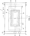
- Fig. 1 is a plan view illustrating a schematic configuration of a wavelength variable interference filter 5 according to a first embodiment.
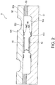
- Fig. 2 is a sectional view illustrating the wavelength variable interference filter 5 taken along the line A-A in Fig. 1 .
- the wavelength variable interference filter 5 includes a translucent fixed substrate 51 and a movable substrate 52.
- the fixed substrate 51 and the movable substrate 52 are formed of, for example, quartz crystal or any of various kinds of glass such as soda glass, crystalline glass, quartz glass, lead glass, potassium glass, borosilicate glass, non-alkali glass.
- the fixed substrate 51 and the movable substrate 52 are bound together by bonding by a bonding film 53 formed of a plasma polymerized film that has, for example, siloxane as a main component.
- a fixed reflection film 54 (a first reflection film) is formed on a counter face of the fixed substrate 51 facing the movable substrate 52.
- a movable reflection film 55 (a second reflection film) is formed on a counter face of the movable substrate 52 facing the fixed substrate 51.
- the fixed reflection film 54 and the movable reflection film 55 are disposed to face each other across a gap G (air gap G).
- an electrostatic actuator 56 is used to adjust (change) the dimension (gap dimension) of the gap G is formed.
- the electrostatic actuator 56 includes a fixed electrode 561 formed on the fixed substrate 51 and a movable electrode 562 formed on the movable substrate 52.
- a plan view in a substrate thickness direction of the fixed substrate 51 or the movable substrate 52 that is, a plan view when the wavelength variable interference filter 5 is viewed in a film thickness direction of the fixed reflection film 54 or the movable reflection film 55, is referred to as a filter plan view.
- a central point of the fixed reflection film 54 and a central point of the movable reflection film 55 match each other and the central points of the reflection films 54 and 55 in the plan view are indicated by O.
- the fixed substrate 51 (a first substrate) and includes an electrode-disposed groove 511 and a reflection-film-disposed portion 512 formed by, for example, etching, as illustrated in Fig. 2 .
- One end side (a side C1-C2 in Fig. 1 ) of the fixed substrate 51 protrudes outwards from a substrate edge (a side C5-C6 in Fig. 1 ) of the movable substrate 52 and configures a first terminal extraction portion 514.
- the electrode-disposed groove 511 is formed in a rectangular annular shape centering on the filter central point O of the fixed substrate 51 in the filter plan view.
- the reflection-film-disposed portion 512 is formed to protrude from a bottom of the electrode-disposed groove 511 to the side of the movable substrate 52 in the filter sectional view.
- the fixed electrode 561 of the electrostatic actuator 56 is formed on a groove bottom surface of the electrode-disposed groove 511.
- the fixed reflection film 54 is formed on a protruding front-edge surface of the reflection-film-disposed portion 512.
- an electrode extraction groove (not illustrated) extending toward the outer circumference of the fixed substrate 51 from the electrode-disposed groove 511 is formed.
- the fixed electrode 561 is formed in, for example, a rectangular annular shape. As illustrated in Fig. 1 , an opening is formed in a part close to the side C1-C2. An insulation film for ensuring insulation with the movable electrode 562 may be configured to be stacked on the fixed electrode 561.
- the fixed electrode 561 includes a fixed lead electrode 563 that extends along the electrode extraction groove up to the first terminal extraction portion 514.
- the reflection-film-disposed portion 512 protrudes toward the movable substrate 52 from the bottom of the electrode-disposed groove 511.
- the fixed reflection film 54 that is formed in a rectangular shape in the filter plan view is formed on the protruding front-end surface of the reflection-film-disposed portion 512.
- the fixed reflection film 54 is configured with a dielectric multilayer in which high refractive layers (for example, Si) and low refractive layers (for example, SiO 2 ) are alternately stacked.
- An optical film that has desired reflection characteristics can be formed by controlling layer thickness dimensions of each high refractive layer and each low refractive layer.
- a conductive film formed of, for example, an electrode material such as ITO is stacked on the surface of the fixed reflection film 54 on the side of the movable substrate 52.
- the fixed reflection film 54 for example, a reflection film such as an Ag alloy that has high reflectance characteristics with respect to a wide wavelength region may be used.
- a first detection electrode 541 that is connected to the outer circumference of the fixed reflection film 54 (conductive film) and extends toward the first terminal extraction portion 514 through an opening of the fixed electrode 561 is formed.
- the first detection electrode 541 is formed simultaneously at the time of forming the fixed reflection film 54.
- the first detection electrode 541 may be formed of a different material from the fixed reflection film 54, for example, gold, etc. that is further appropriate for wiring connection with an external device.
- a part (movable portion 521) of the movable substrate 52 is displaced toward the fixed substrate 51 so that a gap dimension between the fixed reflection film 54 and the movable reflection film 55 is changed.
- the movable substrate 52 includes a rectangular movable portion 521 centering on the filter central point O in the filter plan view, as illustrated in Fig. 1 , a holding portion 522 having the same axis of the movable portion 521, and a substrate outer circumference portion 525 formed outside of the holding portion 522.
- one end side protrudes outwards from a substrate edge (a side C3-C4 in Fig. 1 ) of the fixed substrate 51 and configures the second terminal extraction portion 524.
- the movable portion 521 is formed with a diameter greater than at least a diameter of the outer circumference of the reflection-film-disposed portion 512.
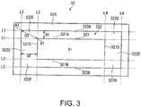
- Fig. 3 is a plan view illustrating the movable substrate 52.
- the movable portion 521 is formed in a rectangular shape in the filter plan view. That is, the movable portion 521 has long sides 521A and 521B which are a pair of first sides, and short sides 521C and 521D which are a pair of second sides.
- the movable reflection film 55 and the movable electrode 562 are formed on the movable portion 521.
- the movable electrode 562 is formed outboard of the outer circumference of the movable reflection film 55 and is disposed to face the fixed electrode 561 via a gap.
- the movable electrode 562 is formed in a rectangular annular shape.
- an opening is formed in a part close to the side C7-C8.
- an insulation film may be stacked on the movable electrode 562.
- the electrostatic actuator 56 is formed in a region in which the movable electrode 562 and the fixed electrode 561 overlap each other (a region by right and upward diagonal lines in Fig. 1 ).
- the electrostatic actuator 56 is disposed to have a shape point-symmetric with respect to the filter central point O in the filter plan view. Accordingly, an electrostatic attraction generated at the time of applying a voltage to the electrostatic actuator 56 is also applied to the position point-symmetric with respect to the filter central point O, and thus the movable portion 521 can be displaced toward the fixed substrate 51 with good balance.
- a movable lead electrode 564 extending toward a second terminal extraction portion 524 is formed in the movable electrode 562.
- the movable lead electrode 564 is disposed at a position facing the electrode extraction groove formed in the fixed substrate 51.
- the movable reflection film 55 has a rectangular shape in the filter plan view, is formed in a central portion of the surface of the movable portion 521 facing the fixed substrate 51, and faces the fixed reflection film 54 across the gap G.
- a dielectric multiplayer in which a high refractive layer (for example, Si) and a low refractive layer (for example, SiO 2 ) are stacked can be used.
- a conductive film formed of, for example, an electrode material such as ITO is installed on the surface of the movable reflection film 55, as in the fixed reflection film 54.
- a reflection film such as an Ag alloy that has high reflectance characteristics with respect to a wide wavelength region may be used as in the fixed reflection film 54.
- a second detection electrode 551 that is connected to the outer circumference of the movable reflection film 55 (conductive film) and extends toward the second terminal extraction portion 524 through an opening of the movable electrode 562 is formed.
- the gap G may be greater than the gap between the electrodes 561 and 562 depending on a measurement target wavelength band.
- the holding portion 522 is a diaphragm surrounding the circumference of the movable portion 521 and is formed with a thickness dimension less than the movable portion 521.
- the holding portion 522 is more easily bent than the movable portion 521 and can displace the movable portion 521 toward the fixed substrate 51 by a slight electrostatic attraction. Since the movable portion 521 has the greater thickness and rigidity than those of the holding portion 522, a change in the shape of the movable portion 521 is suppressed even when the holding portion 522 is drawn to the side of the fixed substrate 51 by the electrostatic attraction.
- the holding portion 522 is formed by etching the movable substrate 52.
- the internal surface of the groove formed in the movable substrate 52 can be formed as a curved surface by the etching.
- the etching may be performed on the movable substrate 52 from the side of the fixed substrate 51 or both the side of the fixed substrate 51 and the opposite side to the fixed substrate 51.
- the holding portion 522 includes a long-side holding portion 522A which is a first holding portion formed along a long side 521A of the movable portion 521, a long-side holding portion 522B which is a first holding portion formed along a long side 521B of the movable portion 521, a short-side holding portion 522C which is a second holding portion formed along a short side 521C of the movable portion 521, and a short-side holding portion 522D which is a second holding portion formed along a short side 521D of the movable portion 521.
- a long-side holding portion 522A which is a first holding portion formed along a long side 521A of the movable portion 521
- a long-side holding portion 522B which is a first holding portion formed along a long side 521B of the movable portion 521
- a short-side holding portion 522C which is a second holding portion formed along a short side 521C of the movable portion 5
- the long-side holding portions 522A and 522B are formed in a rectangular shape in the filter plan view. Edges in a direction along the long sides 521A and 521B (also referred to as a long-side direction or a first direction) are located on the same straight line as the short sides 521C and 521D.
- the short-side holding portions 522C and 522D are formed in a rectangular shape in the filter plan view. Edge frames in a direction oriented along the short sides 521C and 521D (also referred to as a short-side direction or a second direction) are located on the same straight line as the long sides 521A and 521B.
- the holding portion 522 includes a corner holding portion 522E surrounded by a pair of lines L1 formed in the long-side direction in contact with the outer circumference of the long-side holding portion 522A and a pair of lines L2 formed in the short-side direction in contact with the outer circumference of the short-side holding portion 522C in the filter plan view.
- a corner holding portion 522E surrounded by a pair of lines L1 formed in the long-side direction in contact with the outer circumference of the long-side holding portion 522A and a pair of lines L2 formed in the short-side direction in contact with the outer circumference of the short-side holding portion 522C in the filter plan view.
- One of the corner holding portions continuing to one of the short-side holding portions and one of the long-side holding portion at the dotted lines in Fig.3 .
- the holding portion 522 includes a corner holding portion 522F surrounded by the lines L2 and a pair of lines L3 formed in the long-side direction in contact with the outer circumference of the long-side holding portion 522B, a corner holding portion 522G surrounded by the lines L1 and a pair of lines L4 formed in the short-side direction in contact with the outer circumference of the short-side holding portion 522D, and a corner holing portion 522H surrounded by the lines L3 and the lines L4.
- a dimension D2 in the long-side direction in the short-side holding portions 522C and 522D is longer than a dimension D1 in the short-side direction in the long-side holding portions 522A and 522B. Therefore, the short-side holding portions 522C and 522D have lower rigidity than the long-side holding portions 522A and 522B.
- a distance D3 between a vertex A1 which is the closest to the filter central point O and a vertex A2 which is the farthest from the filter central point O in the corner holding portions 522E and 522H is longer than the dimensions D1 and D2. Therefore, the corner holding portions 522E and 522H have lower rigidity than the long-side holding portions 522A and 522B and the short-side holding portions 522C and 522D.
- the substrate outer circumference portion 525 is formed circumferentially outside of the holding portion 522 in the filter plan view.
- the surface of the substrate outer circumference portion 525 facing the fixed substrate 51 is bonded to the fixed substrate 51 via the bonding film 53.
- the gap dimension of a space (the gap G) between the fixed reflection film 54 and the movable reflection film 55 can be changed by applying a driving voltage from the fixed lead electrode 563 and the movable lead electrode 564 to the fixed electrode 561 and the movable electrode 562 included in the electrostatic actuator 56.
- a high-frequency voltage between the fixed reflection film 54 (conductive film) and the movable reflection film 55 (conductive film) via the first detection electrode 541 and the second detection electrode 551, it is possible to convert electrostatic capacitance between the reflection films 54 and 55 into a voltage value for measurement.
- By performing feedback control on the driving voltage applied to the electrostatic actuator 56 based on the measured electrostatic capacitance it is possible to control the gap dimensions of the gap G with high precision.
- the rigidity of the short-side holding portions 522C and 522D is lower than the rigidity of the long-side holding portions 522A and 522B.
- the rigidity of the short-side holding portions 522C and 522D is the same as the rigidity of the long-side holding portions 522A and 522B
- the short-side holding portions 522C and 522D are more easily bent when the movable portion 521 is displaced.
- a force by which the short-side holding portions 522C and 522D draw the movable portion 521 is weakened. Therefore, it is possible to reduce the bending amount of the movable portion 521 in the long-side direction. Accordingly, it is possible to also suppress the bending of the movable reflection film 55 formed in the movable portion 521, it is possible to suppress a variation in an output wavelength in the plane, and thus it is possible to realize the wavelength variable interference filter 5 with high precision.
- the rigidity of the corner holding portions 522E and 522H is lower than the rigidity of the long-side holding portions 522A and 522B and the short-side holding portions 522C and 522D.
- the corner holding portions 522E to 522H are more easily bent when the movable portion 521 is displaced.
- a force by which the corner holding portions 522E to 522H draw the movable portion 521 is weakened. Therefore, the movable portion 521 is rarely bent.
- the rigidity of the short-side holding portions 522C and 522D is set to be lower than the rigidity of the long-side holding portions 522A and 522B by causing the dimension D2 of the short-side holding portions 522C and 522D to be longer than the dimension D1 of the long-side holding portions 522A and 522B.
- a manufacturing process can be further simplified.
- the long-side holding portions 522A and 522B and the short-side holding portions 522C and 522D can be formed merely by forming a mask pattern in a shape appropriate to the long-side holding portions 522A and 522B and the short-side holding portions 522C and 522D. Therefore, it is possible to avoid an increase in the manufacturing process.
- a wavelength variable interference filter according to a second embodiment is different from the wavelength variable interference filter 5 according to the first embodiment in a planar shape of the long-side holding portions 522A and 522B in the movable substrate.
- the remaining configuration is the same as the wavelength variable interference filter according to the first embodiment.
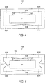
- Fig. 4 is a plan view illustrating a movable substrate 52A according to the second embodiment.
- the same reference numerals are given to the same elements as that of the movable substrate 52 according to the first embodiment.
- an outer circumference of the long-side holding portions 522A and 522B of the movable substrate 52A in contact with the substrate outer circumference portion 525 is hollowed to be curved toward the movable portion 521 in the filter plan view.
- the dimension D1 is gradually shortened from both ends in contact with the corner holding portions 522E and 522G toward the center thereof.
- the dimension D1 is gradually shortened from both ends in contact with the corner holding portions 522F and 522H toward the center thereof.
- the rigidity of the long-side holding portions 522A and 522B is progressively lowered in the filter plan view as a distance from the center of the movable portion 521, that is, the filter central point O, increases.
- the rigidity of the long-side holding portion is progressively lowered in the direction in the long side as a distance from a normal of the long side passing through the center of the movable portion increases.
- the rigidity of the long-side holding portions 522A and 522B is progressively lowered in the long-side direction as the distance from the filter central point O increases.
- the long-side holding portions 522A and 522B are easily bent at a position at which the distance from the center is longer.
- a force drawing the movable portion 521 is weakened. Accordingly, it is possible to cause a displacement amount of the movable portion 521 to be constant in the long-side direction, and thus it is possible to reduce the bending of the movable portion 521 in the long-side direction.
- a wavelength variable interference filter according to a third embodiment is different from the wavelength variable interference filter according to the second embodiment in a planar shape of the short-side holding portions 522C and 522D in the movable substrate.
- the remaining configuration is the same as the wavelength variable interference filter according to the second embodiment.
- Fig. 5 is a plan view illustrating a movable substrate 52B according to the third embodiment of the invention.
- the same reference numerals are given to the same elements as that of the movable substrate 52 according to the first and second embodiment.
- an outer circumference of the short-side holding portions 522C and 522D of the movable substrate 52B in contact with the substrate outer circumference portion 525 is hollowed to be curved toward the movable portion 521 in the filter plan view.
- the dimension D2 is gradually shortened from both ends in contact with the corner holding portions 522E and 522F to the center thereof in the short-side direction.
- the dimension D2 is gradually shortened from both ends in contact with the corner holding portions 522G and 522H to the center thereof in the short-side direction.
- the rigidity of the short-side holding portions 522C and 522D is progressively lowered in the filter plan view as a distance from the center of the movable portion 521, that is, the filter central point O, increases.
- the rigidity of the short-side holding portion is progressively lowered in the direction along the short side as a distance from a normal of the short side passing through the center of the movable portion increases.
- the dimension D1 of the long-side holding portions 522A and 522B may be uniform. As in the second embodiment, however, the dimension D1 may be gradually shortened from both ends to the center thereof in the long-side direction.
- the rigidity of the short-side holding portions 522C and 522D is progressively lowered in the short-side direction as the distance from the filter central point O increases.
- the short-side holding portions 522C and 522D are easily bent at a position at which the distance from the center is longer.
- a force drawing the movable portion 521 is weakened. Accordingly, it is possible to cause a displacement amount of the movable portion 521 to be constant in the short-side direction, and it is possible to reduce bending of the movable portion 521 in the short-side direction.
- a wavelength variable interference filter according to a fourth embodiment is different from the wavelength variable interference filter according to the first to third embodiments in that a holding portion in the movable substrate includes a protruding holding portion that protrudes from an outer circumference of corner holding portions 522E to 522H.
- the remaining configuration is the same as the wavelength variable interference filter according to the first to third embodiments.
- a holding portion of the movable substrate 52C according to the fourth embodiment includes a protruding holding portion 522I protruding in a direction away from the movable portion 521 from an outer circumference of the corner holding portion 522E, an outer circumference of a part of the short-side holding portion 522C continuing with the corner holding portion 522E, and an outer circumference of a part of the long-side holding portion 522A continuing with the corner holding portion 522E in the filter plan view, as illustrated in Fig. 6 .
- the protruding holding portion 522I protrudes in a direction from the filter central point O to the corner holding portion 522E.
- the protruding holding portion 522I may protrude from one outer circumference of the outer circumference of the corner holding portion 522E, the outer circumference of a part of the long-side holding portion 522A continuing with the corner holding portion 522E, and the outer circumference of a part of the short-side holding portion 522C continuing with the corner holding portion 522E.
- the holding portion of the movable substrate 52C includes the protruding holding portion 522I that similarly protrudes from the corner holding portions 522F to 522H.
- the holding portion includes the protruding holding portion 5221.
- the protruding holding portion 522I is bent and a force by which the corner holding portions 522F to 522H draw the movable portion 521 is weakened.
- the movable portion 521 is rarely bent. Accordingly, it is possible to suppress a variation in the output wavelength in a plane.
- the protruding holding portion 522I is continuous with at least one of a part of the long-side holding portions 522A and 522B and the short-side holding portions 522C and 522D. Therefore, when the movable portion 521 is displaced, the protruding holding portion 522I is bent and a force by which at least the one part draws the movable portion 521 is weakened. Therefore, compared to a case in which the protruding holding portion 522I does not continue with the one part, a force by which an corner portion of the movable portion 521 is drawn by the holding portion can be weakened. Thus, the movable portion 521 is further rarely bent.
- the protruding holding portion 522I protrudes in a direction away from the movable portion 521 from the outer circumferences of the corner holding portions 522F to 522H. Therefore, for example, as in the case in which the protruding holding portion protrudes in a direction approaching the movable portion 521 from the outer circumferences of the corner holding portions 522F to 522H, it is not necessary to form a corner portion of the movable portion 521 in a shape appropriate to the protruding holding portion. Accordingly, it is not necessary to overly enlarge the movable portion with respect to the rectangular reflection film more than necessary.
- a wavelength variable interference filter according to a fifth embodiment is different from the wavelength variable interference filter according to the fourth embodiment in that the position and the shape of a protruding holding portion are different.
- the remaining configuration is the same as the wavelength variable interference filter according to the fourth embodiment.
- a holding portion of the movable substrate 52D according to the fifth embodiment includes a protruding holding portion 522J that protrudes in the long-side direction from the outer circumference of the corner holding portion 522E and the outer circumference of a part of the short-side holding portion 522C continuing with the corner holding portion 522E in the filter plan view, as illustrated in Fig. 7 .
- the protruding holding portion 522J may protrude in the short-side direction from the outer circumference of the corner holding portion 522E and the outer circumference of a part of the long-side holding portion 522A continuing with the corner holding portion 522E in the filter plan view.
- the protruding holding portion 522J may protrude in the long-side direction from the outer circumference of the corner holding portion 522E and the outer circumference of a part of the short-side holding portion 522C continuing with the corner holding portion 522E and may protrude in the short-side direction from the outer circumference of the corner holding portion 522E and the outer circumference of a part of the long-side holding portion 522A continuing with the corner holding portion 522E, simultaneously.
- the holding portion of the movable substrate 52D includes the protruding holding portion 522J that similarly protrudes from the corner holding portions 522F to 522H.
- a force by which a corner portion of the movable portion 521 is drawn by the holding portion can also be weakened.
- the movable portion 521 is further rarely bent.
- the protruding holding portion protrudes in a direction approaching the movable portion 521 from the outer circumferences of the corner holding portions 522F to 522H
- a wavelength variable interference filter according to a sixth embodiment is different from the wavelength variable interference filter according to the fourth and fifth embodiments in that the position and the shape of a protruding holding portion are different.
- the remaining elements is the same as the wavelength variable interference filter according to the fourth and fifth embodiments.
- the holding portion of the movable substrate 52E includes a protruding holding portion 522K that protrudes in a direction approaching the movable portion 521 from a vertex A1 closest to the filter center point O in the corner holding portion 522E, the outer circumference of a part of the long-side holding portion 522A continuing with the corner holding portion 522E, and the outer circumference of a part of the short-side holding portion 522C continuing with the corner holding portion 522E in the filter plan view, as illustrated in Fig. 8 .
- the protruding holding portion 522K is a triangular shape in the filter plan view.
- the holding portion of the movable substrate 52E also includes the protruding holding portion 522K that similarly protrudes from the corner holding portions 522F to 522H.
- a force by which a corner portion of the movable portion 521 is drawn by the holding portion can also be weakened.
- the movable portion 521 is further rarely bent.
- Fig. 9 is a sectional view illustrating a schematic configuration of a spectroscope 17.
- the spectroscope 17 is an optical module and includes a light source unit 171, an optical filter device 172, a light receiving unit 173, a light guiding unit 174, and a casing 175, as illustrated in Fig. 9 .
- the spectroscope 17 radiates illumination light from the light source unit 171 to a measurement position R on a measurement target A and causes a light component reflected from the measurement position R to be incident on the optical filter device 172 by the light guiding unit 174. Then, the optical filter device 172 causes light with a predetermined wavelength to exit (transmit) from the reflected light and causes the light receiving unit 173 to receive the light.
- the optical filter device 172 can select a transmission wavelength under the control of a control unit (not illustrated) and can perform spectrometry of light from the measurement position R on the measurement target A by measuring the amount of the light with each wavelength of the visible light.
- the light source unit 171 includes a light source 171A and a condensing unit 171B.
- the light source unit 171 radiates light emitted from the light source 171A to the measurement position R of the measurement target A from a normal direction to the surface of the measurement target A.
- a light source capable of emitting light with each wavelength in the visible light band is preferable as the light source 171A.
- a halogen lamp, a xenon lamp, or a white LED can be exemplified as the light source 171A.
- a white LED which can be easily installed in a restricted space is preferable.
- the condensing unit 171B is configured with, for example, a condensing lens and collects light from the light source 171A to the measurement position R. In Fig. 9 , only one lens (condensing lens) is displayed in the condensing unit 171B, but a plurality of lenses may be used.
- the optical filter device 172 includes a casing 6 and the wavelength variable interference filter 5 accommodated in the casing 6.
- the casing 6 has an accommodation space therein and the wavelength variable interference filter 5 is accommodated in the accommodation space.
- the casing 6 includes terminal portions connected to the fixed lead electrode 563, the movable lead electrode 564, the first detection electrode 541, and the second detection electrode 551 of the wavelength variable interference filter.
- the terminal portions are connected to the control unit. Based on an instruction signal from the control unit, a predetermined voltage is applied to the electrostatic actuator 56 of the wavelength variable interference filter 5, and light with a wavelength corresponding to the applied voltage is accordingly emitted from the wavelength variable interference filter 5.
- Electrostatic capacitance corresponding to the gap dimension between the reflection films 54 and 55 is detected based on signals from the first detection electrode 541 and the second detection electrode 551.
- the light receiving unit 173 is disposed on an optical axis of the wavelength variable interference filter 5 and receives light transmitted through the wavelength variable interference filter 5. Then, the light receiving unit 173 outputs a detection signal (current value) corresponding to an amount of received light under the control of the control unit.
- the detection signal output by the light receiving unit 173 is input to the control unit via an I-V converter (not illustrated), an amplifier (not illustrated), and an AD converter (not illustrated).
- the light guiding unit 174 includes a reflection mirror 174A and a bandpass filter 174B.
- the light guiding unit 174 reflects light reflected at 45° from the surface of the measurement target A at the measurement position R to the optical axis of the wavelength variable interference filter 5 by the reflection mirror 174A.
- the bandpass filter 174B cuts ultraviolet light and infrared light, and transmits the light of the visible light band (for example, 380 nm to 720 nm).
- light with the visible light band is incident on the wavelength variable interference filter 5 and light with a wavelength selected from the visible light band by the wavelength variable interference filter 5 is received by the light receiving unit 173.
- the spectroscope 17 includes the wavelength variable interference filter described in the foregoing first to sixth embodiments and the light receiving unit 173 that receives light transmitted through the wavelength variable interference filter.
- the wavelength variable interference filter can reduce a variation of wavelength of transmitted light in the plane when the gap dimension of the gap G is controlled, as described above and thus can transmit light with a desired wavelength with high spectroscopic precision. Accordingly, by allowing the light receiving unit 173 to receive the light, it is possible to perform the spectroscopic measurement on a measurement target with high precision.
- the rigidity of the short-side holding portions 522C and 522D is set to be lower than the rigidity of the long-side holding portions 522A and 522B by causing the dimension D2 of the short-side holding portions 522C and 522D to be longer than the dimension D1 of the long-side holding portions 522A and 522B, but the invention is not limited thereto.
- the rigidity of the short-side holding portions 522C and 522D may be set to be lower than the rigidity of the long-side holding portions 522A and 522B by causing the dimension in the thickness direction of the short-side holding portions 522C and 522D to be shorter than the dimension in the thickness direction of the long-side holding portions 522A and 522B.
- the rigidity of the short-side holding portions 522C and 522D may be set to be lower than the rigidity of the long-side holding portion 522A and 522B.
- the opening area can be set according to the size of an opening of the hole H1 or the number of holes H1 per unit area.
- the rigidity of the long-side holding portions 522A and 522B is progressively lowered as the distance from the filter central point O increases by gradually shortening the dimension D1 of the long-side holding portions 522A and 522B from both ends to the center in the long-side direction, but the invention is not limited thereto.
- the rigidity of the long-side holding portions 522A and 522B may be lowered as the distance from the filter central point O increases.
- the rigidity of the long-side holding portions 522A and 522B may be lowered as the distance from the filter central point O increases.
- the rigidity of the short-side holding portions 522C and 522D is progressively lowered as the distance from the filter central point O increases by gradually shortening the dimension D2 of the short-side holding portions 522C and 522D from both ends to the center in the short-side direction, but the invention is not limited thereto.
- the rigidity of the short-side holding portions 522C and 522D may be lowered as the distance from the filter central point O increases.
- the rigidity of the short-side holding portions 522C and 522D may be lowered as the distance from the filter central point O increases.
- the holding portion includes corner portions in the filter plan view, but the corner portions may be round.
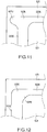
- Fig. 11 illustrates the holding portion according to the fifth embodiment in which a corner portion is rounded and longitudinally extended.
- Fig. 12 illustrates the holding portion according to the sixth embodiment in which a corner portion is rounded.
- the holding portion in which the corner portion is rounded with the shape of an etching mask pattern can be formed.
- the outer circumference in contact with the substrate outer circumference portion 525 is hollowed to be curved toward the movable portion 521 in the filter plan view.
- the dimension D1 is gradually shortened from both ends to the center in the long-side direction, but the invention is not limited thereto.
- the circumference in contact with the movable portion 521 may be hollowed to be curved toward the substrate outer circumference portion 525 in the filter plan view so that the dimension D1 is gradually shortened from both ends to the center in the long-side direction.
- the long sides of the movable portion 521 may be curved in the filter plan view. That is, the long sides of the movable portion according to the invention may include not only straight sides but also curved sides.
- the outer circumference in contact with the substrate outer circumference portion 525 is hollowed to be curved toward the movable portion 521 in the filter plan view.
- the dimension D2 is gradually shortened from both ends to the center in the short-side direction, but the invention is not limited thereto.
- the outer circumference in contact with the movable portion 521 may be hollowed to be curved toward the substrate outer circumference portion 525 in the filter plan view so that the dimension D2 is gradually shortened from both ends to the center in the short-side direction.
- the short sides of the movable portion 521 may be curved in the filter plan view. That is, the short sides of the movable portion according to the invention may include not only straight sides but also curved sides.
- the protrusion holding portion may also protrude from only a part of the outer circumference of the angled holding portions 522E to 522H.
- the protrusion holding portion preferably continues with at least one of parts of the long-side holding portions 522A and 522B and the short-side holding portions 522C and 522D since the force by which an angled portion of the movable portion 521 is drawn by the holding portion can be further weakened.
- the holding portion has the smaller dimension in the thickness direction than the movable portion 521 and supports the movable portion 521 so that the movable portion 521 can be displaced, but the invention is not limited thereto.
- the holding portion may be formed of a material with lower rigidity than the movable portion 521 and may be more easily bent than the movable portion 521 to support the movable portion 521 so that the movable portion 521 can be displaced.
- the holding portion may be more easily bent than the movable portion 521 so that the movable portion 521 can be displaced. That is, the holding portion may have lower rigidity than the movable portion 521.
- the movable portion 521 has the rectangular shape in the filter plan view, but the invention is not limited thereto.
- the movable portion 521 may have an elongated shape that has a major axis, such as an elliptical shape or a square shape.
- the rigidity of a minor-axis holding portion along the minor axis of the movable portion 521 is set to be lower than the rigidity of a major-axis holding portion along the major axis of the movable portion 521 in the holding portion, so that a difference between a bending amount in the major axis direction of the movable portion 521 and a bending amount in the minor axis direction of the movable portion 521 can be reduced.
- protruding holding portions may be formed with the corner holding portions 522E to 522H so that the movable portion 521 can be rarely bent.
- the light-transmissive wavelength variable interference filter that disperses light with a predetermined wavelength from incident light and transmits the light has been exemplified as the wavelength variable interference filter, but the invention is not limited thereto.
- a light reflective wavelength variable interference filter that disperses light with a predetermined wavelength from incident light and reflects the light may be used as the wavelength variable interference filter.
- the fixed lead electrode 563 and the first detection electrode 541 are formed in the first terminal extraction portion 514 and the movable lead electrode 564 and the second detection electrode 551 are formed in the second terminal extraction portion 524, but the invention is not limited thereto.
- the fixed lead electrode 563, the first detection electrode 541, the movable lead electrode 564, and the second detection electrode 551 may be formed in only one of the first terminal extraction portion 514 and the second terminal extraction portion 524.
- the movable electrode 562 is formed in the movable portion 521, but the invention is not limited thereto.
- the movable electrode 562 may be formed in the holding portion 522 that holds the movable portion 521. Accordingly, the area of the movable portion 521 can be further decreased.
- the fixed electrode 561 is formed in a region overlapping with the movable electrode 562 in the filter plan view to configure the electrostatic actuator 56.
Landscapes
- Physics & Mathematics (AREA)
- General Physics & Mathematics (AREA)
- Optics & Photonics (AREA)
- Spectroscopy & Molecular Physics (AREA)
- Mechanical Light Control Or Optical Switches (AREA)
- Spectrometry And Color Measurement (AREA)
- Optical Filters (AREA)
- Micromachines (AREA)
Abstract
Description
- The present invention relates to a wavelength variable interference filter and an optical module.
- In the related art, there is a wavelength variable interference filter that includes a pair of reflection films (for example, see
JP-A-2010-139552 - In such a wavelength variable interference filter, a movable portion on which the reflection film is installed and a holding portion which surrounds the outer circumference of the movable portion and holds the movable portion so that the movable portion is displaceable are formed in a substrate. When the movable portion is displaced, a gap amount between a pair of reflection films is changed. Thus, the light that is transmitted through the wavelength variable interference filter can be controlled based on its wavelength relative to the gap amount.
- Incidentally, the wavelength variable interference filter can be combined for use with a light receiving sensor that receives light transmitted through the wavelength variable interference filter. Therefore, when a light receiving surface of the light receiving sensor is rectangular or square, the planar shapes of the reflection film and the movable portion are also rectangular or square. However, when the movable portion is rectangular or square, the following problem occurs.
- To prevent the reflection films from being bent, displacement is necessary without bending the movable portion.
- However, when applying a force to a flat plate in its thickness direction, in case sides of the flat plate is fixed, a displacement amount of a central position is larger than a displacement amount of a periphery position. Defining a difference of the magnitude of displacement amounts as a bending amount, when rigidity of the holding portion is uniform, the bending amount of the movable portion in a longer side direction is larger than the bending amount of the movable portion in a shorter side direction. Therefore, the gap amount is irregular in the plane of the reflection film.
- When the movable portion is rectangular or square, it is more difficult for a portion of the holding portion contacting with a corner of the movable portion to be bent than other portions of the holding portion. For this reason, when the movable portion is displaced, there is a problem that a corner portion of the movable portion is drawn by the holding portion and the movable portion is easily bent comparing the case when the movable portion is circular shape.
- Further, when the movable portion is bent as described above, there is a problem that the reflection film is also bent, the wavelength of light output from the wavelength variable interference filter varies in a plane of the reflection film, and the precision of the wavelength variable interference filter degrades.
- An advantage of some aspects of the invention is that it provides a wavelength variable interference filter and an optical module capable of suppressing the degradation of the precision of the wavelength variable interference filter due to the bending of a movable portion.
- A wavelength variable interference filter according to an application example of the invention comprises: a first substrate; a first reflection film that is disposed on the first substrate; a second substrate that opposes the first substrate; and second reflection film that is disposed on the second substrate,the second reflection film facing the first reflection film. The second substrate includes a movable portion and a holding portion, the holding portion surrounding an outer circumference of the movable portion and holding the movable portion. The movable portion includes long and short sides in a plan view. The holding portion includes a long-side holding portion formed along a long side of the movable portion, and a short-side holding portion formed along a short side of the movable portion. A rigidity of the short-side holding portion is lower than a rigidity of the long-side holding portion.
- In this application example, the rigidity of the short-side holding portion is lower than the rigidity of the long-side holding portion. In this configuration, compared to a case in which the rigidity of the short-side holding portion is the same as the rigidity of the long-side holding portion, the short-side holding portion is easily bent when the movable portion is displaced. Thus, a force by which the short-side holding portion draws the movable portion is weakened. Therefore, it is possible to reduce the bending of the movable portion in the long-side direction. Accordingly, it is possible to also suppress bending of the second movable reflection film formed on the movable portion, it is possible to suppress a variation in an output wavelength in the plane of the second movable reflection film, and thus it is possible to realize the wavelength variable interference filter with high precision.
- In the wavelength variable interference filter according to the application example, it is preferable that the rigidity of the long-side holding portion is progressively lowered in a direction along the long side as a distance from a center of the movable portion increases. The rigidity of the long-side holding portion is progressively lowered in the direction along the long side as the distance from a normal of the long side passing through the center of the movable portion increases.
- When the rigidity of the holding portion is uniform, a displacement amount of the movable portion is smaller as a distance from the center in the long-side direction increases. In the application example, however, when the movable portion is displaced, the long-side holding portion is easily bent at a position at which the distance from the center is longer, that is, a position at which the distance from the normal of the long side passing through the center of the movable portion is longer in the direction along the long side. Thus, a force drawing the movable portion by the holding portion is weakened.
- Therefore, it is possible to cause a displacement amount of the movable portion to be constant in the long-side direction, and thus it is possible to reduce the bending of the movable portion in the long-side direction.
- In the wavelength variable interference filter according to the application example, it is preferable that the rigidity of the short-side holding portion is progressively lowered in a direction along the short side as a distance from the center of the movable portion increases. The rigidity of the short-side holding portion is progressively lowered in the direction along the short side as the distance from a normal of the short side passing through the center of the movable portion increases.
- When the rigidity of the holding portion is uniform, a displacement amount of the movable portion is smaller as a distance from the center in the short-side direction increases . In the application example, however, when the movable portion is displaced, the short-side holding portion is easily bent at a position at which the distance from the center is longer , that is, a position at which the distance from the normal of the short side passing through the center of the movable portion increases in the direction along the short side. Thus, a force drawing the movable portion by the holding portion is weakened.
- Therefore, it is possible to cause a displacement amount of the movable portion to be constant in the short-side direction, and thus it is possible to reduce the bending of the movable portion in the short-side direction.
- In the wavelength variable interference filter according to the application example, it is preferable that the holding portion includes a corner holding portion that is disposed between the long-side holding portion and the short-side holding portion in the plan view. The rigidity of the corner holding portion is preferably lower than the rigidity of the long-side holding portion and the short-side holding portion. The corner holding portion may be disposed in a region surrounded by a pair of lines formed along the long sides in contact with a circumference of the long-side holding portion close to the movable portion and an outer circumference opposite to the circumference of the long-side holding portion and a pair of lines formed along the short sides in contact with a circumference of the short-side holding portion close to the movable portion and an outer circumference opposite to the circumference of the short-side holding portion.
- According to the application example with this configuration, compared to a case in which the rigidity of the corner holding portion is the same as the rigidity of the long-side holding portion or the short-side holding portion, the corner holding portion is easily bent when the movable portion is displaced. Thus, a force by which the corner holding portion drawing the movable portion is weakened. Therefore, the movable portion is rarely bent.
- In the wavelength variable interference filter according to the application example, it is preferable that a thickness of the short-side holding portion is less than a thickness of the long-side holding portion.
- According to the application example with this configuration, the rigidity of the short-side holding portion can be lower than the rigidity of the long- side holding portion. For example, a manufacturing process can be further simplified than when using the short-side holding portion is formed of a material with lower rigidity than the long-side holding portion to fabricate the wavelength variable interference filter having the property that the rigidity of the short-side holding portion is lower than the rigidity of the long-side holding portion.
- In the wavelength variable interference filter according to the application example, it is preferable that a length of the short-side holding portion in a direction along the long side of the movable portion is greater than a length of the long-side holding portion in a direction along the short side of the movable portion (i.e., the short side holding portion is wider than the long side holding portion).
- According to the application example with this configuration, the rigidity of the short-side holding portion can be lower than the rigidity of the long-side holding portion.
- For example, when the second substrate is etched to form the holding portion, a mask pattern may be formed in a shape appropriate for the long-side holding portion and the short-side holding portion. Therefore, it is possible to avoid an increase in the manufacturing process.
- In the wavelength variable interference filter according to the application example, it is preferable that a plurality of holes are formed in the holding portion, and an opening area of the holes per unit area in the short-side holding portion is greater than an opening area of the holes in the long-side holding portion.
- According to the application example with this configuration, the rigidity of the short-side holding portion can be lower than the rigidity of the long-side holding portion.
- An optical module according to an application example of the invention includes: the wavelength variable interference filter described above; and a light receiving unit that receives light transmitted through the wavelength variable interference filter.
- According to this application example, it is possible to exit light with a desired target wavelength from the wavelength variable interference filter with high spectroscopic precision. Thus, by allowing the light receiving unit to receive the light, it is possible to accurately measure light intensity of the light with the target wavelength included in incident light.
- Embodiments of the invention will be described with reference to the accompanying drawings, wherein like numbers reference like elements.
-
Fig. 1 is a plan view illustrating a schematic configuration of a wavelength variable interference filter according to a first embodiment of the invention. -
Fig. 2 is a sectional view illustrating the wavelength variable interference filter taken along the line A-A inFig. 1 . -
Fig. 3 is a plan view illustrating a movable substrate according to the first embodiment. -
Fig. 4 is a plan view illustrating a movable substrate according to a second embodiment of the invention. -
Fig. 5 is a plan view illustrating a movable substrate according to a third embodiment of the invention. -
Fig. 6 is a plan view illustrating a movable substrate according to a fourth embodiment of the invention. -
Fig. 7 is a plan view illustrating a movable substrate according to a fifth embodiment of the invention. -
Fig. 8 is a plan view illustrating a movable substrate according to a sixth embodiment of the invention. -
Fig. 9 is a sectional view illustrating a schematic configuration of a spectroscope according to a seventh embodiment of the invention. -
Fig. 10 is a plan view illustrating a movable substrate according to another embodiment of the invention. -
Fig. 11 is a plan view illustrating a movable substrate according to still another embodiment of the invention. -
Fig. 12 is a plan view illustrating a movable substrate according to further still another embodiment of the invention. -
Fig. 13 is a plan view illustrating a movable substrate according to further still another embodiment of the invention. -
Fig. 14 is a plan view illustrating a movable substrate according to further still another embodiment of the invention. -
Fig. 15 is a sectional view illustrating a wavelength variable interference filter according to further still another embodiment of the invention. - Hereinafter, a wavelength variable interference filter according to a first embodiment of the invention will be described.
-
Fig. 1 is a plan view illustrating a schematic configuration of a wavelengthvariable interference filter 5 according to a first embodiment. -
Fig. 2 is a sectional view illustrating the wavelengthvariable interference filter 5 taken along the line A-A inFig. 1 . - As illustrated in
Figs. 1 and2 , the wavelengthvariable interference filter 5 includes a translucent fixedsubstrate 51 and amovable substrate 52. The fixedsubstrate 51 and themovable substrate 52 are formed of, for example, quartz crystal or any of various kinds of glass such as soda glass, crystalline glass, quartz glass, lead glass, potassium glass, borosilicate glass, non-alkali glass. The fixedsubstrate 51 and themovable substrate 52 are bound together by bonding by abonding film 53 formed of a plasma polymerized film that has, for example, siloxane as a main component. - A fixed reflection film 54 (a first reflection film) is formed on a counter face of the fixed
substrate 51 facing themovable substrate 52. A movable reflection film 55(a second reflection film) is formed on a counter face of themovable substrate 52 facing the fixedsubstrate 51. The fixedreflection film 54 and themovable reflection film 55 are disposed to face each other across a gap G (air gap G). - In the wavelength
variable interference filter 5, anelectrostatic actuator 56 is used to adjust (change) the dimension (gap dimension) of the gap G is formed. Theelectrostatic actuator 56 includes a fixedelectrode 561 formed on the fixedsubstrate 51 and amovable electrode 562 formed on themovable substrate 52. - In the following description, a plan view in a substrate thickness direction of the fixed
substrate 51 or themovable substrate 52, that is, a plan view when the wavelengthvariable interference filter 5 is viewed in a film thickness direction of the fixedreflection film 54 or themovable reflection film 55, is referred to as a filter plan view. In the embodiment, in the filter plan view, a central point of the fixedreflection film 54 and a central point of themovable reflection film 55 match each other and the central points of thereflection films - The fixed substrate 51 (a first substrate) and includes an electrode-disposed
groove 511 and a reflection-film-disposedportion 512 formed by, for example, etching, as illustrated inFig. 2 . One end side (a side C1-C2 inFig. 1 ) of the fixedsubstrate 51 protrudes outwards from a substrate edge (a side C5-C6 inFig. 1 ) of themovable substrate 52 and configures a firstterminal extraction portion 514. - The electrode-disposed
groove 511 is formed in a rectangular annular shape centering on the filter central point O of the fixedsubstrate 51 in the filter plan view. The reflection-film-disposedportion 512 is formed to protrude from a bottom of the electrode-disposedgroove 511 to the side of themovable substrate 52 in the filter sectional view. The fixedelectrode 561 of theelectrostatic actuator 56 is formed on a groove bottom surface of the electrode-disposedgroove 511. The fixedreflection film 54 is formed on a protruding front-edge surface of the reflection-film-disposedportion 512. - In the fixed
substrate 51, an electrode extraction groove (not illustrated) extending toward the outer circumference of the fixedsubstrate 51 from the electrode-disposedgroove 511 is formed. - The fixed
electrode 561 is formed in, for example, a rectangular annular shape. As illustrated inFig. 1 , an opening is formed in a part close to the side C1-C2. An insulation film for ensuring insulation with themovable electrode 562 may be configured to be stacked on the fixedelectrode 561. - The fixed
electrode 561 includes a fixedlead electrode 563 that extends along the electrode extraction groove up to the firstterminal extraction portion 514. - As illustrated in
Fig. 2 , the reflection-film-disposedportion 512 protrudes toward themovable substrate 52 from the bottom of the electrode-disposedgroove 511. - The fixed
reflection film 54 that is formed in a rectangular shape in the filter plan view is formed on the protruding front-end surface of the reflection-film-disposedportion 512. - The fixed
reflection film 54 is configured with a dielectric multilayer in which high refractive layers (for example, Si) and low refractive layers (for example, SiO2) are alternately stacked. An optical film that has desired reflection characteristics can be formed by controlling layer thickness dimensions of each high refractive layer and each low refractive layer. - A conductive film formed of, for example, an electrode material such as ITO is stacked on the surface of the fixed
reflection film 54 on the side of themovable substrate 52. - As the fixed
reflection film 54, for example, a reflection film such as an Ag alloy that has high reflectance characteristics with respect to a wide wavelength region may be used. - On the fixed
substrate 51, as illustrated inFig. 1 , afirst detection electrode 541 that is connected to the outer circumference of the fixed reflection film 54 (conductive film) and extends toward the firstterminal extraction portion 514 through an opening of the fixedelectrode 561 is formed. Thefirst detection electrode 541 is formed simultaneously at the time of forming the fixedreflection film 54. Thefirst detection electrode 541 may be formed of a different material from the fixedreflection film 54, for example, gold, etc. that is further appropriate for wiring connection with an external device. - When an electrostatic attraction is applied by the
electrostatic actuator 56, a part (movable portion 521) of themovable substrate 52 is displaced toward the fixedsubstrate 51 so that a gap dimension between the fixedreflection film 54 and themovable reflection film 55 is changed. - The
movable substrate 52 includes a rectangularmovable portion 521 centering on the filter central point O in the filter plan view, as illustrated inFig. 1 , a holdingportion 522 having the same axis of themovable portion 521, and a substrateouter circumference portion 525 formed outside of the holdingportion 522. - In the
movable substrate 52, as illustrated inFig. 1 , one end side (a side C7-C8 inFig. 1 ) protrudes outwards from a substrate edge (a side C3-C4 inFig. 1 ) of the fixedsubstrate 51 and configures the secondterminal extraction portion 524. - In the filter plan view, the
movable portion 521 is formed with a diameter greater than at least a diameter of the outer circumference of the reflection-film-disposedportion 512. -
Fig. 3 is a plan view illustrating themovable substrate 52. As illustrated inFig. 3 , themovable portion 521 is formed in a rectangular shape in the filter plan view. That is, themovable portion 521 haslong sides short sides 521C and 521D which are a pair of second sides. - As illustrated in
Figs. 1 and2 , themovable reflection film 55 and themovable electrode 562 are formed on themovable portion 521. - In the filter plan view, the
movable electrode 562 is formed outboard of the outer circumference of themovable reflection film 55 and is disposed to face the fixedelectrode 561 via a gap. Themovable electrode 562 is formed in a rectangular annular shape. As illustrated inFig. 1 , an opening is formed in a part close to the side C7-C8. As in the fixedelectrode 561, an insulation film may be stacked on themovable electrode 562. - Here, as illustrated in
Fig. 1 , in the filter plan view, theelectrostatic actuator 56 is formed in a region in which themovable electrode 562 and the fixedelectrode 561 overlap each other (a region by right and upward diagonal lines inFig. 1 ). As illustrated inFig. 1 , theelectrostatic actuator 56 is disposed to have a shape point-symmetric with respect to the filter central point O in the filter plan view. Accordingly, an electrostatic attraction generated at the time of applying a voltage to theelectrostatic actuator 56 is also applied to the position point-symmetric with respect to the filter central point O, and thus themovable portion 521 can be displaced toward the fixedsubstrate 51 with good balance. - As illustrated in
Fig. 1 , in themovable electrode 562, amovable lead electrode 564 extending toward a secondterminal extraction portion 524 is formed. Themovable lead electrode 564 is disposed at a position facing the electrode extraction groove formed in the fixedsubstrate 51. - The
movable reflection film 55 has a rectangular shape in the filter plan view, is formed in a central portion of the surface of themovable portion 521 facing the fixedsubstrate 51, and faces the fixedreflection film 54 across the gap G. As themovable reflection film 55, a dielectric multiplayer in which a high refractive layer (for example, Si) and a low refractive layer (for example, SiO2) are stacked can be used. - A conductive film formed of, for example, an electrode material such as ITO is installed on the surface of the
movable reflection film 55, as in the fixedreflection film 54. - As the
movable reflection film 55, for example, a reflection film such as an Ag alloy that has high reflectance characteristics with respect to a wide wavelength region may be used as in the fixedreflection film 54. - In the
movable substrate 52, as illustrated inFig. 1 , asecond detection electrode 551 that is connected to the outer circumference of the movable reflection film 55 (conductive film) and extends toward the secondterminal extraction portion 524 through an opening of themovable electrode 562 is formed. - In the embodiment, as illustrated in
Fig. 2 , an example in which a gap between theelectrodes electrodes - The holding
portion 522 is a diaphragm surrounding the circumference of themovable portion 521 and is formed with a thickness dimension less than themovable portion 521. The holdingportion 522 is more easily bent than themovable portion 521 and can displace themovable portion 521 toward the fixedsubstrate 51 by a slight electrostatic attraction. Since themovable portion 521 has the greater thickness and rigidity than those of the holdingportion 522, a change in the shape of themovable portion 521 is suppressed even when the holdingportion 522 is drawn to the side of the fixedsubstrate 51 by the electrostatic attraction. - The holding
portion 522 is formed by etching themovable substrate 52. In the embodiment, since isotropic etching is used, the internal surface of the groove formed in themovable substrate 52 can be formed as a curved surface by the etching. Thus, it is possible to suppress the concentration of stress on a part of the internal surface of the groove. In the embodiment, themovable substrate 52 is etched from the opposite side to the fixedsubstrate 51, but the invention is not limited thereto. That is, the etching may be performed on themovable substrate 52 from the side of the fixedsubstrate 51 or both the side of the fixedsubstrate 51 and the opposite side to the fixedsubstrate 51. - Next, the shape of the holding
portion 522 will be described in detail. As illustrated inFig. 3 , the holdingportion 522 includes a long-side holding portion 522A which is a first holding portion formed along along side 521A of themovable portion 521, a long-side holding portion 522B which is a first holding portion formed along along side 521B of themovable portion 521, a short-side holding portion 522C which is a second holding portion formed along a short side 521C of themovable portion 521, and a short-side holding portion 522D which is a second holding portion formed along ashort side 521D of themovable portion 521. - The long-
side holding portions long sides short sides 521C and 521D. - The short-
side holding portions short sides 521C and 521D (also referred to as a short-side direction or a second direction) are located on the same straight line as thelong sides - Further, the holding
portion 522 includes acorner holding portion 522E surrounded by a pair of lines L1 formed in the long-side direction in contact with the outer circumference of the long-side holding portion 522A and a pair of lines L2 formed in the short-side direction in contact with the outer circumference of the short-side holding portion 522C in the filter plan view. One of the corner holding portions continuing to one of the short-side holding portions and one of the long-side holding portion at the dotted lines inFig.3 . Further, the holdingportion 522 includes acorner holding portion 522F surrounded by the lines L2 and a pair of lines L3 formed in the long-side direction in contact with the outer circumference of the long-side holding portion 522B, acorner holding portion 522G surrounded by the lines L1 and a pair of lines L4 formed in the short-side direction in contact with the outer circumference of the short-side holding portion 522D, and acorner holing portion 522H surrounded by the lines L3 and the lines L4. - In the embodiment, a dimension D2 in the long-side direction in the short-
side holding portions side holding portions side holding portions side holding portions - In the filter plan view, a distance D3 between a vertex A1 which is the closest to the filter central point O and a vertex A2 which is the farthest from the filter central point O in the
corner holding portions corner holding portions side holding portions side holding portions - The substrate
outer circumference portion 525 is formed circumferentially outside of the holdingportion 522 in the filter plan view. The surface of the substrateouter circumference portion 525 facing the fixedsubstrate 51 is bonded to the fixedsubstrate 51 via thebonding film 53. - In the foregoing wavelength
variable interference filter 5, the gap dimension of a space (the gap G) between the fixedreflection film 54 and themovable reflection film 55 can be changed by applying a driving voltage from the fixedlead electrode 563 and themovable lead electrode 564 to the fixedelectrode 561 and themovable electrode 562 included in theelectrostatic actuator 56. By applying a high-frequency voltage between the fixed reflection film 54 (conductive film) and the movable reflection film 55 (conductive film) via thefirst detection electrode 541 and thesecond detection electrode 551, it is possible to convert electrostatic capacitance between thereflection films electrostatic actuator 56 based on the measured electrostatic capacitance, it is possible to control the gap dimensions of the gap G with high precision. - In the embodiment, the rigidity of the short-
side holding portions side holding portions side holding portions side holding portions side holding portions movable portion 521 is displaced. Thus, a force by which the short-side holding portions movable portion 521 is weakened. Therefore, it is possible to reduce the bending amount of themovable portion 521 in the long-side direction. Accordingly, it is possible to also suppress the bending of themovable reflection film 55 formed in themovable portion 521, it is possible to suppress a variation in an output wavelength in the plane, and thus it is possible to realize the wavelengthvariable interference filter 5 with high precision. - In the embodiment, the rigidity of the
corner holding portions side holding portions side holding portions corner holding portions 522E to 522H is the same as the rigidity of the long-side holding portions side holding portions corner holding portions 522E to 522H are more easily bent when themovable portion 521 is displaced. Thus, a force by which thecorner holding portions 522E to 522H draw themovable portion 521 is weakened. Therefore, themovable portion 521 is rarely bent. - In the embodiment, the rigidity of the short-
side holding portions side holding portions side holding portions side holding portions side holding portions side holding portions movable substrate 52 is etched to form the holdingportions 522, the long-side holding portions side holding portions side holding portions side holding portions - A wavelength variable interference filter according to a second embodiment is different from the wavelength
variable interference filter 5 according to the first embodiment in a planar shape of the long-side holding portions -
Fig. 4 is a plan view illustrating amovable substrate 52A according to the second embodiment. The same reference numerals are given to the same elements as that of themovable substrate 52 according to the first embodiment. - As illustrated in
Fig. 4 , an outer circumference of the long-side holding portions movable substrate 52A in contact with the substrateouter circumference portion 525 is hollowed to be curved toward themovable portion 521 in the filter plan view. - That is, in the long-
side holding portion 522A, the dimension D1 is gradually shortened from both ends in contact with thecorner holding portions side holding portion 522B, the dimension D1 is gradually shortened from both ends in contact with thecorner holding portions - In this configuration, the rigidity of the long-
side holding portions movable portion 521, that is, the filter central point O, increases. The rigidity of the long-side holding portion is progressively lowered in the direction in the long side as a distance from a normal of the long side passing through the center of the movable portion increases. - In the embodiment, the rigidity of the long-
side holding portions movable portion 521 is displaced, the long-side holding portions movable portion 521 is weakened. Accordingly, it is possible to cause a displacement amount of themovable portion 521 to be constant in the long-side direction, and thus it is possible to reduce the bending of themovable portion 521 in the long-side direction. - Because of the same formations as those according to the first embodiment, it is possible to obtain the same operational effects.
- A wavelength variable interference filter according to a third embodiment is different from the wavelength variable interference filter according to the second embodiment in a planar shape of the short-
side holding portions -
Fig. 5 is a plan view illustrating amovable substrate 52B according to the third embodiment of the invention. The same reference numerals are given to the same elements as that of themovable substrate 52 according to the first and second embodiment. - As illustrated in
Fig. 5 , an outer circumference of the short-side holding portions movable substrate 52B in contact with the substrateouter circumference portion 525 is hollowed to be curved toward themovable portion 521 in the filter plan view. - That is, in the short-
side holding portion 522C, the dimension D2 is gradually shortened from both ends in contact with thecorner holding portions side holding portion 522D, the dimension D2 is gradually shortened from both ends in contact with thecorner holding portions - In this configuration, the rigidity of the short-
side holding portions movable portion 521, that is, the filter central point O, increases. The rigidity of the short-side holding portion is progressively lowered in the direction along the short side as a distance from a normal of the short side passing through the center of the movable portion increases. - The dimension D1 of the long-
side holding portions - In the embodiment, the rigidity of the short-
side holding portions movable portion 521 is displaced, the short-side holding portions movable portion 521 is weakened. Accordingly, it is possible to cause a displacement amount of themovable portion 521 to be constant in the short-side direction, and it is possible to reduce bending of themovable portion 521 in the short-side direction. - Because of the same formations as those according to the first and second embodiments, it is possible to obtain the same operational effects.
- A wavelength variable interference filter according to a fourth embodiment is different from the wavelength variable interference filter according to the first to third embodiments in that a holding portion in the movable substrate includes a protruding holding portion that protrudes from an outer circumference of
corner holding portions 522E to 522H. The remaining configuration is the same as the wavelength variable interference filter according to the first to third embodiments. - A holding portion of the
movable substrate 52C according to the fourth embodiment includes a protruding holding portion 522I protruding in a direction away from themovable portion 521 from an outer circumference of thecorner holding portion 522E, an outer circumference of a part of the short-side holding portion 522C continuing with thecorner holding portion 522E, and an outer circumference of a part of the long-side holding portion 522A continuing with thecorner holding portion 522E in the filter plan view, as illustrated inFig. 6 . The protruding holding portion 522I protrudes in a direction from the filter central point O to thecorner holding portion 522E. - The protruding holding portion 522I may protrude from one outer circumference of the outer circumference of the
corner holding portion 522E, the outer circumference of a part of the long-side holding portion 522A continuing with thecorner holding portion 522E, and the outer circumference of a part of the short-side holding portion 522C continuing with thecorner holding portion 522E. - Although not illustrated, the holding portion of the
movable substrate 52C includes the protruding holding portion 522I that similarly protrudes from thecorner holding portions 522F to 522H. - According to the embodiment, the holding portion includes the protruding holding
portion 5221. In this configuration, when themovable portion 521 is displaced, the protruding holding portion 522I is bent and a force by which thecorner holding portions 522F to 522H draw themovable portion 521 is weakened. Thus, themovable portion 521 is rarely bent. Accordingly, it is possible to suppress a variation in the output wavelength in a plane. - The protruding holding portion 522I is continuous with at least one of a part of the long-
side holding portions side holding portions movable portion 521 is displaced, the protruding holding portion 522I is bent and a force by which at least the one part draws themovable portion 521 is weakened. Therefore, compared to a case in which the protruding holding portion 522I does not continue with the one part, a force by which an corner portion of themovable portion 521 is drawn by the holding portion can be weakened. Thus, themovable portion 521 is further rarely bent. - The protruding holding portion 522I protrudes in a direction away from the
movable portion 521 from the outer circumferences of thecorner holding portions 522F to 522H. Therefore, for example, as in the case in which the protruding holding portion protrudes in a direction approaching themovable portion 521 from the outer circumferences of thecorner holding portions 522F to 522H, it is not necessary to form a corner portion of themovable portion 521 in a shape appropriate to the protruding holding portion. Accordingly, it is not necessary to overly enlarge the movable portion with respect to the rectangular reflection film more than necessary. - In addition, it is possible to obtain the same operational effects as those of the first to third embodiments.
- A wavelength variable interference filter according to a fifth embodiment is different from the wavelength variable interference filter according to the fourth embodiment in that the position and the shape of a protruding holding portion are different. The remaining configuration is the same as the wavelength variable interference filter according to the fourth embodiment.
- A holding portion of the
movable substrate 52D according to the fifth embodiment includes a protruding holdingportion 522J that protrudes in the long-side direction from the outer circumference of thecorner holding portion 522E and the outer circumference of a part of the short-side holding portion 522C continuing with thecorner holding portion 522E in the filter plan view, as illustrated inFig. 7 . - The protruding holding
portion 522J may protrude in the short-side direction from the outer circumference of thecorner holding portion 522E and the outer circumference of a part of the long-side holding portion 522A continuing with thecorner holding portion 522E in the filter plan view. Alternatively, the protruding holdingportion 522J may protrude in the long-side direction from the outer circumference of thecorner holding portion 522E and the outer circumference of a part of the short-side holding portion 522C continuing with thecorner holding portion 522E and may protrude in the short-side direction from the outer circumference of thecorner holding portion 522E and the outer circumference of a part of the long-side holding portion 522A continuing with thecorner holding portion 522E, simultaneously. - Although not illustrated, the holding portion of the
movable substrate 52D includes the protruding holdingportion 522J that similarly protrudes from thecorner holding portions 522F to 522H. - In the embodiment, as in the fourth embodiment, a force by which a corner portion of the
movable portion 521 is drawn by the holding portion can also be weakened. Thus, themovable portion 521 is further rarely bent. For example, comparing to the case in which the protruding holding portion protrudes in a direction approaching themovable portion 521 from the outer circumferences of thecorner holding portions 522F to 522H, it is not necessary to form a corner portion of themovable portion 521 in a shape appropriate to the protruding holding portion. Accordingly, it is not necessary to overly enlarge the movable portion with respect to the rectangular reflection film. - In addition, it is possible to obtain the same operational effects as those of the first to third embodiments.
- A wavelength variable interference filter according to a sixth embodiment is different from the wavelength variable interference filter according to the fourth and fifth embodiments in that the position and the shape of a protruding holding portion are different. The remaining elements is the same as the wavelength variable interference filter according to the fourth and fifth embodiments.
- The holding portion of the
movable substrate 52E according to the sixth embodiment includes a protruding holdingportion 522K that protrudes in a direction approaching themovable portion 521 from a vertex A1 closest to the filter center point O in thecorner holding portion 522E, the outer circumference of a part of the long-side holding portion 522A continuing with thecorner holding portion 522E, and the outer circumference of a part of the short-side holding portion 522C continuing with thecorner holding portion 522E in the filter plan view, as illustrated inFig. 8 . The protruding holdingportion 522K is a triangular shape in the filter plan view. - Although not illustrated, the holding portion of the
movable substrate 52E also includes the protruding holdingportion 522K that similarly protrudes from thecorner holding portions 522F to 522H. - In the embodiment, as in the fourth and fifth embodiments, a force by which a corner portion of the
movable portion 521 is drawn by the holding portion can also be weakened. Thus, themovable portion 521 is further rarely bent. - In addition, it is possible to obtain the same operational effects as those of the first to third embodiments.
- Next, a seventh embodiment of the invention will be described.
- In the seventh embodiment, an example of a spectroscope in which the wavelength variable interference filter described in the foregoing first to sixth embodiments is incorporated will be described with reference to the drawing. Here, the description will be made assuming that the wavelength
variable interference filter 5 according to the first embodiment is incorporated as a representative of the wavelength variable interference filters according to the embodiment. -
Fig. 9 is a sectional view illustrating a schematic configuration of aspectroscope 17. - The
spectroscope 17 is an optical module and includes alight source unit 171, anoptical filter device 172, alight receiving unit 173, alight guiding unit 174, and acasing 175, as illustrated inFig. 9 . - The
spectroscope 17 radiates illumination light from thelight source unit 171 to a measurement position R on a measurement target A and causes a light component reflected from the measurement position R to be incident on theoptical filter device 172 by thelight guiding unit 174. Then, theoptical filter device 172 causes light with a predetermined wavelength to exit (transmit) from the reflected light and causes thelight receiving unit 173 to receive the light. Theoptical filter device 172 can select a transmission wavelength under the control of a control unit (not illustrated) and can perform spectrometry of light from the measurement position R on the measurement target A by measuring the amount of the light with each wavelength of the visible light. - The
light source unit 171 includes alight source 171A and acondensing unit 171B. Thelight source unit 171 radiates light emitted from thelight source 171A to the measurement position R of the measurement target A from a normal direction to the surface of the measurement target A. - A light source capable of emitting light with each wavelength in the visible light band is preferable as the
light source 171A. For example, a halogen lamp, a xenon lamp, or a white LED can be exemplified as thelight source 171A. In particular, a white LED which can be easily installed in a restricted space is preferable. The condensingunit 171B is configured with, for example, a condensing lens and collects light from thelight source 171A to the measurement position R. InFig. 9 , only one lens (condensing lens) is displayed in thecondensing unit 171B, but a plurality of lenses may be used. - The
optical filter device 172 includes acasing 6 and the wavelengthvariable interference filter 5 accommodated in thecasing 6. Thecasing 6 has an accommodation space therein and the wavelengthvariable interference filter 5 is accommodated in the accommodation space. Thecasing 6 includes terminal portions connected to the fixedlead electrode 563, themovable lead electrode 564, thefirst detection electrode 541, and thesecond detection electrode 551 of the wavelength variable interference filter. The terminal portions are connected to the control unit. Based on an instruction signal from the control unit, a predetermined voltage is applied to theelectrostatic actuator 56 of the wavelengthvariable interference filter 5, and light with a wavelength corresponding to the applied voltage is accordingly emitted from the wavelengthvariable interference filter 5. Electrostatic capacitance corresponding to the gap dimension between thereflection films first detection electrode 541 and thesecond detection electrode 551. - As illustrated in
Fig. 9 , thelight receiving unit 173 is disposed on an optical axis of the wavelengthvariable interference filter 5 and receives light transmitted through the wavelengthvariable interference filter 5. Then, thelight receiving unit 173 outputs a detection signal (current value) corresponding to an amount of received light under the control of the control unit. The detection signal output by thelight receiving unit 173 is input to the control unit via an I-V converter (not illustrated), an amplifier (not illustrated), and an AD converter (not illustrated). - The
light guiding unit 174 includes areflection mirror 174A and abandpass filter 174B. - The
light guiding unit 174 reflects light reflected at 45° from the surface of the measurement target A at the measurement position R to the optical axis of the wavelengthvariable interference filter 5 by thereflection mirror 174A. Thebandpass filter 174B cuts ultraviolet light and infrared light, and transmits the light of the visible light band (for example, 380 nm to 720 nm). Thus, light with the visible light band is incident on the wavelengthvariable interference filter 5 and light with a wavelength selected from the visible light band by the wavelengthvariable interference filter 5 is received by thelight receiving unit 173. - The
spectroscope 17 according to the embodiment includes the wavelength variable interference filter described in the foregoing first to sixth embodiments and thelight receiving unit 173 that receives light transmitted through the wavelength variable interference filter. - Here, the wavelength variable interference filter can reduce a variation of wavelength of transmitted light in the plane when the gap dimension of the gap G is controlled, as described above and thus can transmit light with a desired wavelength with high spectroscopic precision. Accordingly, by allowing the
light receiving unit 173 to receive the light, it is possible to perform the spectroscopic measurement on a measurement target with high precision. - The invention is not limited to the above-described embodiments and modifications, improvements, and the like within the scope of the invention are included in the invention.
- For example, in the foregoing first embodiment, the rigidity of the short-
side holding portions side holding portions side holding portions side holding portions - For example, the rigidity of the short-
side holding portions side holding portions side holding portions side holding portions - By forming holes H1 in the long-
side holding portions side holding portions Fig. 10 , and causing an opening area of the holes H1 per unit area to be greater in the short-side holding portions side holding portions side holding portions side holding portion - In the foregoing second and third embodiments, the rigidity of the long-
side holding portions side holding portions - For example, by gradually enlarging the dimension in the thickness direction of the long-
side holding portions side holding portions - By forming the holes H1 in the long-
side holding portion side holding portions - In the foregoing third embodiment, the rigidity of the short-
side holding portions side holding portions - For example, by gradually enlarging the dimension in the thickness direction of the short-
side holding portions side holding portions - By forming the holes H1 in the short-
side holding portions side holding portions - In the wavelength variable interference filter according to the foregoing first to sixth embodiments, the holding portion includes corner portions in the filter plan view, but the corner portions may be round.
- For example,
Fig. 11 illustrates the holding portion according to the fifth embodiment in which a corner portion is rounded and longitudinally extended.Fig. 12 illustrates the holding portion according to the sixth embodiment in which a corner portion is rounded. - In this way, by rounding the corner portion, it is possible to suppress the concentration of stress on a part of the holding portion.
- If the movable substrate is etched to form a holding portion of which a dimension in the thickness direction is less than the
movable portion 521, the holding portion in which the corner portion is rounded with the shape of an etching mask pattern can be formed. - In the foregoing second embodiment, in the long-
side holding portions movable substrate 52A, the outer circumference in contact with the substrateouter circumference portion 525 is hollowed to be curved toward themovable portion 521 in the filter plan view. Thus, the dimension D1 is gradually shortened from both ends to the center in the long-side direction, but the invention is not limited thereto. For example, as illustrated inFig. 13 , in the long-side holding portions movable portion 521 may be hollowed to be curved toward the substrateouter circumference portion 525 in the filter plan view so that the dimension D1 is gradually shortened from both ends to the center in the long-side direction. That is, the long sides of themovable portion 521 may be curved in the filter plan view. That is, the long sides of the movable portion according to the invention may include not only straight sides but also curved sides. - In the foregoing third embodiment, in the short-
side holding portions movable substrate 52B, the outer circumference in contact with the substrateouter circumference portion 525 is hollowed to be curved toward themovable portion 521 in the filter plan view. Thus, the dimension D2 is gradually shortened from both ends to the center in the short-side direction, but the invention is not limited thereto. For example, as illustrated inFig. 14 , in the short-side holding portions movable portion 521 may be hollowed to be curved toward the substrateouter circumference portion 525 in the filter plan view so that the dimension D2 is gradually shortened from both ends to the center in the short-side direction. That is, the short sides of themovable portion 521 may be curved in the filter plan view. That is, the short sides of the movable portion according to the invention may include not only straight sides but also curved sides. - In the foregoing fourth and fifth embodiments, the protrusion holding portion may also protrude from only a part of the outer circumference of the
angled holding portions 522E to 522H. However, the protrusion holding portion preferably continues with at least one of parts of the long-side holding portions side holding portions movable portion 521 is drawn by the holding portion can be further weakened. - In the wavelength variable interference filter according to the foregoing first to sixth embodiments, the holding portion has the smaller dimension in the thickness direction than the
movable portion 521 and supports themovable portion 521 so that themovable portion 521 can be displaced, but the invention is not limited thereto. For example, the holding portion may be formed of a material with lower rigidity than themovable portion 521 and may be more easily bent than themovable portion 521 to support themovable portion 521 so that themovable portion 521 can be displaced. Alternatively, by forming a hole in the holding portion, the holding portion may be more easily bent than themovable portion 521 so that themovable portion 521 can be displaced. That is, the holding portion may have lower rigidity than themovable portion 521. - In the foregoing first to sixth embodiments, the
movable portion 521 has the rectangular shape in the filter plan view, but the invention is not limited thereto. For example, themovable portion 521 may have an elongated shape that has a major axis, such as an elliptical shape or a square shape. - When the
movable portion 521 has an elongated shape, the rigidity of a minor-axis holding portion along the minor axis of themovable portion 521 is set to be lower than the rigidity of a major-axis holding portion along the major axis of themovable portion 521 in the holding portion, so that a difference between a bending amount in the major axis direction of themovable portion 521 and a bending amount in the minor axis direction of themovable portion 521 can be reduced. - When the
movable portion 521 has a square shape, protruding holding portions may be formed with thecorner holding portions 522E to 522H so that themovable portion 521 can be rarely bent. - In the foregoing embodiments, the light-transmissive wavelength variable interference filter that disperses light with a predetermined wavelength from incident light and transmits the light has been exemplified as the wavelength variable interference filter, but the invention is not limited thereto. For example, a light reflective wavelength variable interference filter that disperses light with a predetermined wavelength from incident light and reflects the light may be used as the wavelength variable interference filter.
- In the foregoing embodiments, the fixed
lead electrode 563 and thefirst detection electrode 541 are formed in the firstterminal extraction portion 514 and themovable lead electrode 564 and thesecond detection electrode 551 are formed in the secondterminal extraction portion 524, but the invention is not limited thereto. For example, the fixedlead electrode 563, thefirst detection electrode 541, themovable lead electrode 564, and thesecond detection electrode 551 may be formed in only one of the firstterminal extraction portion 514 and the secondterminal extraction portion 524. - In the foregoing embodiments, the
movable electrode 562 is formed in themovable portion 521, but the invention is not limited thereto. For example, as illustrated inFig. 15 , themovable electrode 562 may be formed in the holdingportion 522 that holds themovable portion 521. Accordingly, the area of themovable portion 521 can be further decreased. At this time, as in the foregoing embodiments, the fixedelectrode 561 is formed in a region overlapping with themovable electrode 562 in the filter plan view to configure theelectrostatic actuator 56. - In addition, the specific structures according to the embodiments of the invention can be appropriately changed to other structures within the scope of the invention.
Claims (12)
- A wavelength variable interference filter (5) comprising:a first substrate (51);a first reflection film (54) that is disposed on the first substrate (51);a second substrate (52) that opposes the first substrate; anda second reflection film (55) that is disposed on the second substrate, the second reflection film (55) facing the first reflection film (54),the second substrate including a movable portion (521) and a holding portion (522), the holding portion (522) surrounding an outer circumference of the movable portion (521) and holding the movable portion (521),wherein the movable portion (521) includes long (521A, B) and short sides (521C, D) in a plan view,wherein the holding portion (522) includes a long-side holding portion (522A, B) formed along a long side (521A, B) of the movable portion (521), and a short-side holding portion (522C, D) formed along a short side (521C, D) of the movable portion (521), andwherein a rigidity of the short-side holding portion (522C, D) is lower than a rigidity of the long-side holding portion (522A, B).
- The wavelength variable interference filter (5) according to claim 1,
wherein the rigidity of the long-side holding portion (522A, B) is progressively lowered in a direction along the long side (521A, B) of the movable portion (521) as a distance from a normal of the long side (521A, B) passing through a center of the movable portion (521) increases. - The wavelength variable interference filter (5) according to claim 1,
wherein the rigidity of the long-side holding portion (522A, B) is progressively lowered in a direction along a major axis of the movable portion (521) as a distance from a normal of the major axis passing through a center of the movable portion (521) increases. - The wavelength variable interference filter (5) according to claim 1,
wherein the rigidity of the short-side holding portion (522C, D) is progressively lowered in a direction along the short side (521C, D) of the movable portion (521) as a distance from a normal of the short side (521C, D) passing through a center of the movable portion (521) increases. - The wavelength variable interference filter (5) according to claim 1,
wherein the rigidity of the short-side holding portion (522C, D) is progressively lowered in a direction along a minor axis of the movable portion (521) as a distance from a normal of the short axis passing through a center of the movable portion (521) increases. - The wavelength variable interference filter (5) according to any one of claims 1 to 5,
wherein the holding portion (522) further includes a corner holding portion (522E-H) disposed between the long-side holding portion (522A, B) and the short-side holding portion (522C, D) in the plan view, and
wherein a rigidity of the corner holding portion (522E-H) is lower than the rigidity of the long-side holding portion (522A, B) and the short-side holding portion (522C, D). - The wavelength variable interference filter (5) according to claim 6,
wherein the corner holding portion (522E-H) is disposed in a region surrounded by a pair of lines (L1, L3) formed along the long sides (521A, B) of the movable portion (521) in contact with a first circumference of the long-side holding portion (522A, B) close to the movable portion (521) and a first outer circumference of the long-side holding portion (522A, B) opposite to the first circumference and a pair of lines (L2, L4) formed along the short sides (521C, D) of the movable portion (521) in contact with a second circumference of the short-side holding portion (522C, D) close to the movable portion (521) and a second outer circumference of the short-side holding portion (522C, D) opposite to the second circumference, and
wherein a rigidity of the corner holding portion (522E-H) is lower than the rigidity of the long-side holding portion (522A, B) and the short-side holding portion (522C, D). - The wavelength variable interference filter (5) according to claim 6 or 7,
wherein the holding portion (522) further includes a protruding holding portion (5221, J, K) that protrudes from an outer circumference of the corner holding portion (522E-H) . - The wavelength variable interference filter (5) according to any one of claims 1 to 8,
wherein a thickness of the short-side holding portion (522C, D) is less than a thickness of the long-side holding portion (522A, B). - The wavelength variable interference filter (5) according to any one of claims 1 to 9,
wherein a length of the short-side holding portion (522C, D) in a direction along the long side (521A, B) of the movable portion (521) is greater than a length of the long-side holding portion (522A, B) in a direction along the short side (521C,D) of the movable portion (521). - The wavelength variable interference filter (5) according to any one of claims 1 to 10,
wherein a plurality of holes are formed in the holding portion (522), and
wherein an opening area of the holes per unit area in the short-side holding portion (522C, D) is greater than an opening area of the holes in the long-side holding portion (522A, B) . - An optical module (17) comprising:the wavelength variable interference filter (5) according to any one of claims 1 to 11; anda light receiving unit (173) that receives light transmitted through the wavelength variable interference filter (5).
Applications Claiming Priority (1)
| Application Number | Priority Date | Filing Date | Title |
|---|---|---|---|
| JP2017037645A JP6926527B2 (en) | 2017-02-28 | 2017-02-28 | Tunable interference filter and optical module |
Publications (2)
| Publication Number | Publication Date |
|---|---|
| EP3367156A1 true EP3367156A1 (en) | 2018-08-29 |
| EP3367156B1 EP3367156B1 (en) | 2021-01-06 |
Family
ID=61521324
Family Applications (1)
| Application Number | Title | Priority Date | Filing Date |
|---|---|---|---|
| EP18158844.3A Active EP3367156B1 (en) | 2017-02-28 | 2018-02-27 | Wavelength variable interference filter and optical module |
Country Status (4)
| Country | Link |
|---|---|
| US (2) | US10746909B2 (en) |
| EP (1) | EP3367156B1 (en) |
| JP (1) | JP6926527B2 (en) |
| CN (1) | CN108508592B (en) |
Families Citing this family (4)
| Publication number | Priority date | Publication date | Assignee | Title |
|---|---|---|---|---|
| JP6926527B2 (en) * | 2017-02-28 | 2021-08-25 | セイコーエプソン株式会社 | Tunable interference filter and optical module |
| JP7181784B2 (en) * | 2018-12-18 | 2022-12-01 | 浜松ホトニクス株式会社 | MONITORING DEVICE, OPTICAL FILTER SYSTEM, MONITORING METHOD, CURRENT GENERATOR |
| JP7200842B2 (en) * | 2019-06-21 | 2023-01-10 | セイコーエプソン株式会社 | Tunable Interference Filter |
| CN114981701B (en) * | 2019-09-25 | 2023-11-21 | 深圳市海谱纳米光学科技有限公司 | Adjustable optical filter device |
Citations (3)
| Publication number | Priority date | Publication date | Assignee | Title |
|---|---|---|---|---|
| JP2010139552A (en) | 2008-12-09 | 2010-06-24 | Seiko Epson Corp | Optical filter and optical module having the same |
| WO2012168545A1 (en) * | 2011-06-06 | 2012-12-13 | Teknologian Tutkimuskeskus Vtt | Micromechanical tunable fabry-perot interferometer and a method for producing the same |
| US20160370230A1 (en) * | 2015-06-18 | 2016-12-22 | Seiko Epson Corporation | Spectroscopic measurement device, image forming apparatus, and spectroscopic measurement method |
Family Cites Families (18)
| Publication number | Priority date | Publication date | Assignee | Title |
|---|---|---|---|---|
| JPH0766982B2 (en) | 1989-03-29 | 1995-07-19 | シャープ株式会社 | Wavelength selective light receiving element |
| WO1999052006A2 (en) * | 1998-04-08 | 1999-10-14 | Etalon, Inc. | Interferometric modulation of radiation |
| JP4111288B2 (en) * | 1998-07-09 | 2008-07-02 | Tdk株式会社 | Wavelength selective photodetector |
| JP2002062505A (en) * | 2000-08-14 | 2002-02-28 | Canon Inc | Projection display device and coherent modulation element used therefor |
| JP2003185941A (en) | 2001-12-20 | 2003-07-03 | Yokogawa Electric Corp | Fabry-Perot filter |
| US7734131B2 (en) | 2006-04-18 | 2010-06-08 | Xerox Corporation | Fabry-Perot tunable filter using a bonded pair of transparent substrates |
| US20070242358A1 (en) * | 2006-04-18 | 2007-10-18 | Xerox Corporation | Fabry-perot tunable filter |
| JP5516358B2 (en) | 2010-11-18 | 2014-06-11 | 株式会社デンソー | Manufacturing method of Fabry-Perot interferometer |
| JP6003168B2 (en) * | 2012-04-11 | 2016-10-05 | セイコーエプソン株式会社 | Wavelength variable interference filter, optical filter device, optical module, and electronic apparatus |
| US9036235B2 (en) * | 2012-05-09 | 2015-05-19 | Axsun Technologies, Inc. | Mechanically balanced optical membrane device for orientation insensitivity |
| CN103293660B (en) * | 2013-05-31 | 2015-06-10 | 华中科技大学 | Miniature F-P (Fabry-Perot) cavity tunable filter and method for manufacturing same |
| JP6384239B2 (en) * | 2014-09-29 | 2018-09-05 | セイコーエプソン株式会社 | Optical filter device, optical module, and electronic apparatus |
| JP6613564B2 (en) * | 2014-12-26 | 2019-12-04 | セイコーエプソン株式会社 | Optical filter device, optical module, and electronic apparatus |
| JP2017009635A (en) * | 2015-06-17 | 2017-01-12 | 株式会社リコー | Piezoelectric actuator device, optical deflector, image projection device and image formation apparatus |
| CN105425384B (en) * | 2015-11-11 | 2018-05-15 | 西北工业大学 | A kind of electromagnetic drive type micro-mechanical adjustable enamel amber wave filter and preparation method thereof |
| CN105549199B (en) * | 2016-01-30 | 2017-11-24 | 西北工业大学 | Electromagnetically driven micromechanical bidirectional tuning enamel amber wave filter and preparation method thereof |
| CN106383377B (en) * | 2016-01-30 | 2019-01-15 | 西北工业大学 | A kind of electromagnetic drive type micro-mechanical adjustable enamel amber filter and preparation method thereof |
| JP6926527B2 (en) * | 2017-02-28 | 2021-08-25 | セイコーエプソン株式会社 | Tunable interference filter and optical module |
-
2017
- 2017-02-28 JP JP2017037645A patent/JP6926527B2/en active Active
-
2018
- 2018-02-14 US US15/896,460 patent/US10746909B2/en active Active
- 2018-02-23 CN CN201810156107.3A patent/CN108508592B/en active Active
- 2018-02-27 EP EP18158844.3A patent/EP3367156B1/en active Active
-
2020
- 2020-07-07 US US16/922,029 patent/US10921503B2/en active Active
Patent Citations (3)
| Publication number | Priority date | Publication date | Assignee | Title |
|---|---|---|---|---|
| JP2010139552A (en) | 2008-12-09 | 2010-06-24 | Seiko Epson Corp | Optical filter and optical module having the same |
| WO2012168545A1 (en) * | 2011-06-06 | 2012-12-13 | Teknologian Tutkimuskeskus Vtt | Micromechanical tunable fabry-perot interferometer and a method for producing the same |
| US20160370230A1 (en) * | 2015-06-18 | 2016-12-22 | Seiko Epson Corporation | Spectroscopic measurement device, image forming apparatus, and spectroscopic measurement method |
Non-Patent Citations (1)
| Title |
|---|
| BYRON A WALMSLEY ET AL: "Design and optimisation of a MEMS-based tunable Fabry-Pérot infrared filter", OPTOELECTRONIC AND MICROELECTRONIC MATERIALS AND DEVICES, 2006 CONFERE NCE ON, IEEE, PI, 1 December 2006 (2006-12-01), pages 272 - 275, XP031201964, ISBN: 978-1-4244-0577-0 * |
Also Published As
| Publication number | Publication date |
|---|---|
| JP2018141933A (en) | 2018-09-13 |
| CN108508592A (en) | 2018-09-07 |
| US10746909B2 (en) | 2020-08-18 |
| JP6926527B2 (en) | 2021-08-25 |
| EP3367156B1 (en) | 2021-01-06 |
| US20200333519A1 (en) | 2020-10-22 |
| US10921503B2 (en) | 2021-02-16 |
| CN108508592B (en) | 2022-01-14 |
| US20180246264A1 (en) | 2018-08-30 |
Similar Documents
| Publication | Publication Date | Title |
|---|---|---|
| US10921503B2 (en) | Wavelength variable interference filter and optical module | |
| JP5641220B2 (en) | Wavelength variable interference filter, optical module, and optical analyzer | |
| US9995862B2 (en) | Optical filter, optical filter module, spectrometric measurement apparatus, and optical apparatus | |
| US9482857B2 (en) | Tunable interference filter, optical module, and photometric analyzer | |
| US20120188646A1 (en) | Variable wavelength interference filter, optical module, and optical analysis device | |
| JP5928992B2 (en) | Method for manufacturing tunable interference filter | |
| US8559111B2 (en) | Interference filter having adhesive and warp reduction grooves | |
| US20150070767A1 (en) | Variable wavelength interference filter, optical module, and optical analyzer | |
| CN103913856A (en) | Image display device | |
| US20120188552A1 (en) | Variable wavelength interference filter, optical module, spectroscopic analyzer, and analyzer | |
| CN103376545A (en) | Variable wavelength interference filter, optical filter device, optical module, and electronic apparatus | |
| JP2011053510A (en) | Wavelength variable interference filter, colorimetry sensor, colorimetry module and method of controlling wavelength variable interference filter | |
| US8797650B2 (en) | Variable wavelength interference filter, optical module, and optical analysis device | |
| JP2013072930A (en) | Wavelength variable interference filter, optical filter device, optical module and electronic apparatus | |
| JP2015161511A (en) | Optical module and electronic equipment | |
| US20150316416A1 (en) | Optical module and imaging system | |
| JP5673075B2 (en) | Tunable interference filter, optical module, and optical analyzer | |
| JP2016048187A (en) | Optical module and electronic device | |
| JP5617621B2 (en) | Wavelength variable interference filter, optical module, and optical analyzer | |
| JP2017040491A (en) | Optical module and spectroscopic device | |
| JP2012141347A (en) | Wavelength variable interference filter, optical module, and optical analyzer | |
| JP2015043103A (en) | Wavelength variable interference filter, optical module, and photometric analyzer | |
| JP6194776B2 (en) | Spectrometer and spectroscopic method | |
| JP2021021813A (en) | Wavelength variable interference filter | |
| JP2013076777A (en) | Wavelength variable interference filter, optical filter device, optical module and electronic apparatus |
Legal Events
| Date | Code | Title | Description |
|---|---|---|---|
| PUAI | Public reference made under article 153(3) epc to a published international application that has entered the european phase |
Free format text: ORIGINAL CODE: 0009012 |
|
| STAA | Information on the status of an ep patent application or granted ep patent |
Free format text: STATUS: THE APPLICATION HAS BEEN PUBLISHED |
|
| AK | Designated contracting states |
Kind code of ref document: A1 Designated state(s): AL AT BE BG CH CY CZ DE DK EE ES FI FR GB GR HR HU IE IS IT LI LT LU LV MC MK MT NL NO PL PT RO RS SE SI SK SM TR |
|
| AX | Request for extension of the european patent |
Extension state: BA ME |
|
| STAA | Information on the status of an ep patent application or granted ep patent |
Free format text: STATUS: REQUEST FOR EXAMINATION WAS MADE |
|
| 17P | Request for examination filed |
Effective date: 20190219 |
|
| RBV | Designated contracting states (corrected) |
Designated state(s): AL AT BE BG CH CY CZ DE DK EE ES FI FR GB GR HR HU IE IS IT LI LT LU LV MC MK MT NL NO PL PT RO RS SE SI SK SM TR |
|
| STAA | Information on the status of an ep patent application or granted ep patent |
Free format text: STATUS: EXAMINATION IS IN PROGRESS |
|
| 17Q | First examination report despatched |
Effective date: 20200303 |
|
| RIC1 | Information provided on ipc code assigned before grant |
Ipc: G02B 26/00 20060101AFI20200730BHEP Ipc: G02B 5/26 20060101ALI20200730BHEP Ipc: G01J 3/26 20060101ALI20200730BHEP Ipc: G02B 5/28 20060101ALI20200730BHEP |
|
| GRAP | Despatch of communication of intention to grant a patent |
Free format text: ORIGINAL CODE: EPIDOSNIGR1 |
|
| STAA | Information on the status of an ep patent application or granted ep patent |
Free format text: STATUS: GRANT OF PATENT IS INTENDED |
|
| INTG | Intention to grant announced |
Effective date: 20200917 |
|
| GRAS | Grant fee paid |
Free format text: ORIGINAL CODE: EPIDOSNIGR3 |
|
| GRAA | (expected) grant |
Free format text: ORIGINAL CODE: 0009210 |
|
| STAA | Information on the status of an ep patent application or granted ep patent |
Free format text: STATUS: THE PATENT HAS BEEN GRANTED |
|
| AK | Designated contracting states |
Kind code of ref document: B1 Designated state(s): AL AT BE BG CH CY CZ DE DK EE ES FI FR GB GR HR HU IE IS IT LI LT LU LV MC MK MT NL NO PL PT RO RS SE SI SK SM TR |
|
| REG | Reference to a national code |
Ref country code: GB Ref legal event code: FG4D |
|
| REG | Reference to a national code |
Ref country code: AT Ref legal event code: REF Ref document number: 1353002 Country of ref document: AT Kind code of ref document: T Effective date: 20210115 Ref country code: CH Ref legal event code: EP |
|
| REG | Reference to a national code |
Ref country code: DE Ref legal event code: R096 Ref document number: 602018011452 Country of ref document: DE |
|
| REG | Reference to a national code |
Ref country code: IE Ref legal event code: FG4D |
|
| REG | Reference to a national code |
Ref country code: NL Ref legal event code: MP Effective date: 20210106 |
|
| REG | Reference to a national code |
Ref country code: AT Ref legal event code: MK05 Ref document number: 1353002 Country of ref document: AT Kind code of ref document: T Effective date: 20210106 |
|
| REG | Reference to a national code |
Ref country code: LT Ref legal event code: MG9D |
|
| PG25 | Lapsed in a contracting state [announced via postgrant information from national office to epo] |
Ref country code: LT Free format text: LAPSE BECAUSE OF FAILURE TO SUBMIT A TRANSLATION OF THE DESCRIPTION OR TO PAY THE FEE WITHIN THE PRESCRIBED TIME-LIMIT Effective date: 20210106 Ref country code: BG Free format text: LAPSE BECAUSE OF FAILURE TO SUBMIT A TRANSLATION OF THE DESCRIPTION OR TO PAY THE FEE WITHIN THE PRESCRIBED TIME-LIMIT Effective date: 20210406 Ref country code: PT Free format text: LAPSE BECAUSE OF FAILURE TO SUBMIT A TRANSLATION OF THE DESCRIPTION OR TO PAY THE FEE WITHIN THE PRESCRIBED TIME-LIMIT Effective date: 20210506 Ref country code: NO Free format text: LAPSE BECAUSE OF FAILURE TO SUBMIT A TRANSLATION OF THE DESCRIPTION OR TO PAY THE FEE WITHIN THE PRESCRIBED TIME-LIMIT Effective date: 20210406 Ref country code: HR Free format text: LAPSE BECAUSE OF FAILURE TO SUBMIT A TRANSLATION OF THE DESCRIPTION OR TO PAY THE FEE WITHIN THE PRESCRIBED TIME-LIMIT Effective date: 20210106 Ref country code: FI Free format text: LAPSE BECAUSE OF FAILURE TO SUBMIT A TRANSLATION OF THE DESCRIPTION OR TO PAY THE FEE WITHIN THE PRESCRIBED TIME-LIMIT Effective date: 20210106 Ref country code: GR Free format text: LAPSE BECAUSE OF FAILURE TO SUBMIT A TRANSLATION OF THE DESCRIPTION OR TO PAY THE FEE WITHIN THE PRESCRIBED TIME-LIMIT Effective date: 20210407 |
|
| PG25 | Lapsed in a contracting state [announced via postgrant information from national office to epo] |
Ref country code: SE Free format text: LAPSE BECAUSE OF FAILURE TO SUBMIT A TRANSLATION OF THE DESCRIPTION OR TO PAY THE FEE WITHIN THE PRESCRIBED TIME-LIMIT Effective date: 20210106 Ref country code: LV Free format text: LAPSE BECAUSE OF FAILURE TO SUBMIT A TRANSLATION OF THE DESCRIPTION OR TO PAY THE FEE WITHIN THE PRESCRIBED TIME-LIMIT Effective date: 20210106 Ref country code: PL Free format text: LAPSE BECAUSE OF FAILURE TO SUBMIT A TRANSLATION OF THE DESCRIPTION OR TO PAY THE FEE WITHIN THE PRESCRIBED TIME-LIMIT Effective date: 20210106 Ref country code: RS Free format text: LAPSE BECAUSE OF FAILURE TO SUBMIT A TRANSLATION OF THE DESCRIPTION OR TO PAY THE FEE WITHIN THE PRESCRIBED TIME-LIMIT Effective date: 20210106 Ref country code: AT Free format text: LAPSE BECAUSE OF FAILURE TO SUBMIT A TRANSLATION OF THE DESCRIPTION OR TO PAY THE FEE WITHIN THE PRESCRIBED TIME-LIMIT Effective date: 20210106 |
|
| PG25 | Lapsed in a contracting state [announced via postgrant information from national office to epo] |
Ref country code: IS Free format text: LAPSE BECAUSE OF FAILURE TO SUBMIT A TRANSLATION OF THE DESCRIPTION OR TO PAY THE FEE WITHIN THE PRESCRIBED TIME-LIMIT Effective date: 20210506 |
|
| REG | Reference to a national code |
Ref country code: DE Ref legal event code: R097 Ref document number: 602018011452 Country of ref document: DE |
|
| REG | Reference to a national code |
Ref country code: BE Ref legal event code: MM Effective date: 20210228 |
|
| PG25 | Lapsed in a contracting state [announced via postgrant information from national office to epo] |
Ref country code: SM Free format text: LAPSE BECAUSE OF FAILURE TO SUBMIT A TRANSLATION OF THE DESCRIPTION OR TO PAY THE FEE WITHIN THE PRESCRIBED TIME-LIMIT Effective date: 20210106 Ref country code: CH Free format text: LAPSE BECAUSE OF NON-PAYMENT OF DUE FEES Effective date: 20210228 Ref country code: LU Free format text: LAPSE BECAUSE OF NON-PAYMENT OF DUE FEES Effective date: 20210227 Ref country code: MC Free format text: LAPSE BECAUSE OF FAILURE TO SUBMIT A TRANSLATION OF THE DESCRIPTION OR TO PAY THE FEE WITHIN THE PRESCRIBED TIME-LIMIT Effective date: 20210106 Ref country code: LI Free format text: LAPSE BECAUSE OF NON-PAYMENT OF DUE FEES Effective date: 20210228 Ref country code: CZ Free format text: LAPSE BECAUSE OF FAILURE TO SUBMIT A TRANSLATION OF THE DESCRIPTION OR TO PAY THE FEE WITHIN THE PRESCRIBED TIME-LIMIT Effective date: 20210106 Ref country code: EE Free format text: LAPSE BECAUSE OF FAILURE TO SUBMIT A TRANSLATION OF THE DESCRIPTION OR TO PAY THE FEE WITHIN THE PRESCRIBED TIME-LIMIT Effective date: 20210106 |
|
| PLBE | No opposition filed within time limit |
Free format text: ORIGINAL CODE: 0009261 |
|
| STAA | Information on the status of an ep patent application or granted ep patent |
Free format text: STATUS: NO OPPOSITION FILED WITHIN TIME LIMIT |
|
| PG25 | Lapsed in a contracting state [announced via postgrant information from national office to epo] |
Ref country code: SK Free format text: LAPSE BECAUSE OF FAILURE TO SUBMIT A TRANSLATION OF THE DESCRIPTION OR TO PAY THE FEE WITHIN THE PRESCRIBED TIME-LIMIT Effective date: 20210106 Ref country code: DK Free format text: LAPSE BECAUSE OF FAILURE TO SUBMIT A TRANSLATION OF THE DESCRIPTION OR TO PAY THE FEE WITHIN THE PRESCRIBED TIME-LIMIT Effective date: 20210106 Ref country code: RO Free format text: LAPSE BECAUSE OF FAILURE TO SUBMIT A TRANSLATION OF THE DESCRIPTION OR TO PAY THE FEE WITHIN THE PRESCRIBED TIME-LIMIT Effective date: 20210106 |
|
| 26N | No opposition filed |
Effective date: 20211007 |
|
| PG25 | Lapsed in a contracting state [announced via postgrant information from national office to epo] |
Ref country code: AL Free format text: LAPSE BECAUSE OF FAILURE TO SUBMIT A TRANSLATION OF THE DESCRIPTION OR TO PAY THE FEE WITHIN THE PRESCRIBED TIME-LIMIT Effective date: 20210106 Ref country code: ES Free format text: LAPSE BECAUSE OF FAILURE TO SUBMIT A TRANSLATION OF THE DESCRIPTION OR TO PAY THE FEE WITHIN THE PRESCRIBED TIME-LIMIT Effective date: 20210106 Ref country code: IE Free format text: LAPSE BECAUSE OF NON-PAYMENT OF DUE FEES Effective date: 20210227 |
|
| PG25 | Lapsed in a contracting state [announced via postgrant information from national office to epo] |
Ref country code: SI Free format text: LAPSE BECAUSE OF FAILURE TO SUBMIT A TRANSLATION OF THE DESCRIPTION OR TO PAY THE FEE WITHIN THE PRESCRIBED TIME-LIMIT Effective date: 20210106 |
|
| PG25 | Lapsed in a contracting state [announced via postgrant information from national office to epo] |
Ref country code: IT Free format text: LAPSE BECAUSE OF FAILURE TO SUBMIT A TRANSLATION OF THE DESCRIPTION OR TO PAY THE FEE WITHIN THE PRESCRIBED TIME-LIMIT Effective date: 20210106 |
|
| PG25 | Lapsed in a contracting state [announced via postgrant information from national office to epo] |
Ref country code: IS Free format text: LAPSE BECAUSE OF FAILURE TO SUBMIT A TRANSLATION OF THE DESCRIPTION OR TO PAY THE FEE WITHIN THE PRESCRIBED TIME-LIMIT Effective date: 20210506 |
|
| PG25 | Lapsed in a contracting state [announced via postgrant information from national office to epo] |
Ref country code: BE Free format text: LAPSE BECAUSE OF NON-PAYMENT OF DUE FEES Effective date: 20210228 |
|
| PG25 | Lapsed in a contracting state [announced via postgrant information from national office to epo] |
Ref country code: NL Free format text: LAPSE BECAUSE OF NON-PAYMENT OF DUE FEES Effective date: 20210206 Ref country code: CY Free format text: LAPSE BECAUSE OF FAILURE TO SUBMIT A TRANSLATION OF THE DESCRIPTION OR TO PAY THE FEE WITHIN THE PRESCRIBED TIME-LIMIT Effective date: 20210106 |
|
| PG25 | Lapsed in a contracting state [announced via postgrant information from national office to epo] |
Ref country code: HU Free format text: LAPSE BECAUSE OF FAILURE TO SUBMIT A TRANSLATION OF THE DESCRIPTION OR TO PAY THE FEE WITHIN THE PRESCRIBED TIME-LIMIT; INVALID AB INITIO Effective date: 20180227 |
|
| PG25 | Lapsed in a contracting state [announced via postgrant information from national office to epo] |
Ref country code: MK Free format text: LAPSE BECAUSE OF FAILURE TO SUBMIT A TRANSLATION OF THE DESCRIPTION OR TO PAY THE FEE WITHIN THE PRESCRIBED TIME-LIMIT Effective date: 20210106 |
|
| PG25 | Lapsed in a contracting state [announced via postgrant information from national office to epo] |
Ref country code: MT Free format text: LAPSE BECAUSE OF FAILURE TO SUBMIT A TRANSLATION OF THE DESCRIPTION OR TO PAY THE FEE WITHIN THE PRESCRIBED TIME-LIMIT Effective date: 20210106 |
|
| PG25 | Lapsed in a contracting state [announced via postgrant information from national office to epo] |
Ref country code: TR Free format text: LAPSE BECAUSE OF FAILURE TO SUBMIT A TRANSLATION OF THE DESCRIPTION OR TO PAY THE FEE WITHIN THE PRESCRIBED TIME-LIMIT Effective date: 20210106 |
|
| PGFP | Annual fee paid to national office [announced via postgrant information from national office to epo] |
Ref country code: FR Payment date: 20251231 Year of fee payment: 9 |
|
| PGFP | Annual fee paid to national office [announced via postgrant information from national office to epo] |
Ref country code: GB Payment date: 20260106 Year of fee payment: 9 |
|
| PGFP | Annual fee paid to national office [announced via postgrant information from national office to epo] |
Ref country code: DE Payment date: 20260102 Year of fee payment: 9 |