EP3367128A1 - Überwachungsanordnung - Google Patents
Überwachungsanordnung Download PDFInfo
- Publication number
- EP3367128A1 EP3367128A1 EP17157309.0A EP17157309A EP3367128A1 EP 3367128 A1 EP3367128 A1 EP 3367128A1 EP 17157309 A EP17157309 A EP 17157309A EP 3367128 A1 EP3367128 A1 EP 3367128A1
- Authority
- EP
- European Patent Office
- Prior art keywords
- monitoring arrangement
- sensor
- arrangement according
- control data
- data
- Prior art date
- Legal status (The legal status is an assumption and is not a legal conclusion. Google has not performed a legal analysis and makes no representation as to the accuracy of the status listed.)
- Granted
Links
Images

Classifications
-
- G—PHYSICS
- G01—MEASURING; TESTING
- G01S—RADIO DIRECTION-FINDING; RADIO NAVIGATION; DETERMINING DISTANCE OR VELOCITY BY USE OF RADIO WAVES; LOCATING OR PRESENCE-DETECTING BY USE OF THE REFLECTION OR RERADIATION OF RADIO WAVES; ANALOGOUS ARRANGEMENTS USING OTHER WAVES
- G01S17/00—Systems using the reflection or reradiation of electromagnetic waves other than radio waves, e.g. lidar systems
- G01S17/02—Systems using the reflection of electromagnetic waves other than radio waves
- G01S17/06—Systems determining position data of a target
-
- G—PHYSICS
- G01—MEASURING; TESTING
- G01D—MEASURING NOT SPECIALLY ADAPTED FOR A SPECIFIC VARIABLE; ARRANGEMENTS FOR MEASURING TWO OR MORE VARIABLES NOT COVERED IN A SINGLE OTHER SUBCLASS; TARIFF METERING APPARATUS; MEASURING OR TESTING NOT OTHERWISE PROVIDED FOR
- G01D5/00—Mechanical means for transferring the output of a sensing member; Means for converting the output of a sensing member to another variable where the form or nature of the sensing member does not constrain the means for converting; Transducers not specially adapted for a specific variable
- G01D5/26—Mechanical means for transferring the output of a sensing member; Means for converting the output of a sensing member to another variable where the form or nature of the sensing member does not constrain the means for converting; Transducers not specially adapted for a specific variable characterised by optical transfer means, i.e. using infrared, visible, or ultraviolet light
- G01D5/32—Mechanical means for transferring the output of a sensing member; Means for converting the output of a sensing member to another variable where the form or nature of the sensing member does not constrain the means for converting; Transducers not specially adapted for a specific variable characterised by optical transfer means, i.e. using infrared, visible, or ultraviolet light with attenuation or whole or partial obturation of beams of light
- G01D5/34—Mechanical means for transferring the output of a sensing member; Means for converting the output of a sensing member to another variable where the form or nature of the sensing member does not constrain the means for converting; Transducers not specially adapted for a specific variable characterised by optical transfer means, i.e. using infrared, visible, or ultraviolet light with attenuation or whole or partial obturation of beams of light the beams of light being detected by photocells
- G01D5/347—Mechanical means for transferring the output of a sensing member; Means for converting the output of a sensing member to another variable where the form or nature of the sensing member does not constrain the means for converting; Transducers not specially adapted for a specific variable characterised by optical transfer means, i.e. using infrared, visible, or ultraviolet light with attenuation or whole or partial obturation of beams of light the beams of light being detected by photocells using displacement encoding scales
- G01D5/34746—Linear encoders
-
- G—PHYSICS
- G01—MEASURING; TESTING
- G01D—MEASURING NOT SPECIALLY ADAPTED FOR A SPECIFIC VARIABLE; ARRANGEMENTS FOR MEASURING TWO OR MORE VARIABLES NOT COVERED IN A SINGLE OTHER SUBCLASS; TARIFF METERING APPARATUS; MEASURING OR TESTING NOT OTHERWISE PROVIDED FOR
- G01D5/00—Mechanical means for transferring the output of a sensing member; Means for converting the output of a sensing member to another variable where the form or nature of the sensing member does not constrain the means for converting; Transducers not specially adapted for a specific variable
- G01D5/26—Mechanical means for transferring the output of a sensing member; Means for converting the output of a sensing member to another variable where the form or nature of the sensing member does not constrain the means for converting; Transducers not specially adapted for a specific variable characterised by optical transfer means, i.e. using infrared, visible, or ultraviolet light
- G01D5/32—Mechanical means for transferring the output of a sensing member; Means for converting the output of a sensing member to another variable where the form or nature of the sensing member does not constrain the means for converting; Transducers not specially adapted for a specific variable characterised by optical transfer means, i.e. using infrared, visible, or ultraviolet light with attenuation or whole or partial obturation of beams of light
- G01D5/34—Mechanical means for transferring the output of a sensing member; Means for converting the output of a sensing member to another variable where the form or nature of the sensing member does not constrain the means for converting; Transducers not specially adapted for a specific variable characterised by optical transfer means, i.e. using infrared, visible, or ultraviolet light with attenuation or whole or partial obturation of beams of light the beams of light being detected by photocells
- G01D5/347—Mechanical means for transferring the output of a sensing member; Means for converting the output of a sensing member to another variable where the form or nature of the sensing member does not constrain the means for converting; Transducers not specially adapted for a specific variable characterised by optical transfer means, i.e. using infrared, visible, or ultraviolet light with attenuation or whole or partial obturation of beams of light the beams of light being detected by photocells using displacement encoding scales
- G01D5/34776—Absolute encoders with analogue or digital scales
- G01D5/34792—Absolute encoders with analogue or digital scales with only digital scales or both digital and incremental scales
-
- G—PHYSICS
- G01—MEASURING; TESTING
- G01S—RADIO DIRECTION-FINDING; RADIO NAVIGATION; DETERMINING DISTANCE OR VELOCITY BY USE OF RADIO WAVES; LOCATING OR PRESENCE-DETECTING BY USE OF THE REFLECTION OR RERADIATION OF RADIO WAVES; ANALOGOUS ARRANGEMENTS USING OTHER WAVES
- G01S17/00—Systems using the reflection or reradiation of electromagnetic waves other than radio waves, e.g. lidar systems
- G01S17/02—Systems using the reflection of electromagnetic waves other than radio waves
- G01S17/06—Systems determining position data of a target
- G01S17/42—Simultaneous measurement of distance and other co-ordinates
-
- G—PHYSICS
- G01—MEASURING; TESTING
- G01S—RADIO DIRECTION-FINDING; RADIO NAVIGATION; DETERMINING DISTANCE OR VELOCITY BY USE OF RADIO WAVES; LOCATING OR PRESENCE-DETECTING BY USE OF THE REFLECTION OR RERADIATION OF RADIO WAVES; ANALOGOUS ARRANGEMENTS USING OTHER WAVES
- G01S17/00—Systems using the reflection or reradiation of electromagnetic waves other than radio waves, e.g. lidar systems
- G01S17/88—Lidar systems specially adapted for specific applications
- G01S17/89—Lidar systems specially adapted for specific applications for mapping or imaging
-
- G—PHYSICS
- G01—MEASURING; TESTING
- G01S—RADIO DIRECTION-FINDING; RADIO NAVIGATION; DETERMINING DISTANCE OR VELOCITY BY USE OF RADIO WAVES; LOCATING OR PRESENCE-DETECTING BY USE OF THE REFLECTION OR RERADIATION OF RADIO WAVES; ANALOGOUS ARRANGEMENTS USING OTHER WAVES
- G01S7/00—Details of systems according to groups G01S13/00, G01S15/00, G01S17/00
- G01S7/48—Details of systems according to groups G01S13/00, G01S15/00, G01S17/00 of systems according to group G01S17/00
- G01S7/497—Means for monitoring or calibrating
Definitions
- the invention relates to a monitoring arrangement according to the preamble of claim 1.
- the monitoring arrangement generally comprises a sensor associated with a plant.
- the sensor is an object detection, which can be used in particular to control the system.
- Such a monitoring arrangement is known from DE 102 11 779 B1 known.
- the monitoring arrangement described therein has an optical sensor with a transmitting light beam emitting transmitter, a receiving light beam receiving receiver, means for guiding the transmitted light beams within a scanning range and an evaluation unit for evaluating the pending at the output of the receiver receiving signals.
- the optical sensor With the optical sensor, the detection of marks, which form a position measuring system takes place. By detecting marks of the position measuring system at two different points in time, the speed of the optical sensor is also determined relative to the position measuring system.
- the optical sensor is particularly advantageously mounted on a vehicle, wherein the position measuring system is arranged stationary on the roadway along which the vehicle is moved.
- a position measuring system with respect to a stationary optoelectronic device can be moved. Due to the continuous detection of the marks of the position measuring system, the current speed and position measured values are continuously determined in the optical sensor and transmitted to the control of the vehicle. In the control these measured values can be used without further evaluation and in particular be used directly without any synchronization effort to control the vehicle. In particular, compliance with predefined speed profiles for the vehicle can be continuously monitored in the control. Together with the current information about the position of the vehicle this can be retracted reproducible and pinpoint on predetermined target positions.
- the invention has for its object to provide a monitoring arrangement with increased functionality.
- the invention relates to a monitoring arrangement with a system associated sensor.
- the sensor has at least one sensor element and an evaluation unit, wherein the sensor element is designed to detect objects within a monitoring area assigned to the installation and the evaluation unit is designed to generate object detection data as a function of sensor signals of the sensor element.
- a memory unit is provided, in which control data generated as a function of the object detection data are stored tamper-proof.
- the basic idea of the invention is thus to use the sensor of the monitoring arrangement not only for object detection.
- the functionality of the sensor and thus of the monitoring arrangement is increased by generating control data as a function of the object detection data of the sensor by means of the sensor or a further unit, which are stored tamper-proof, that is to say a falsification of the control data can be reliably detected.
- the control data thus form fail-safe data, the In particular, they form a time-resolved sequence of control data, by means of which the function of the system and also the function of the sensor can be controlled.
- the senor can be advantageously designed as a safety sensor.
- the safety sensor has a redundantly constructed evaluation unit, in particular in the form of two mutually cyclically monitoring computer units.
- the sensor is used in particular for positioning tasks. This is particularly useful in the case when the system is a vehicle, such as a driverless transport system.
- the sensor is disposed on the vehicle and detects defined, cooperatively located stationary targets in the surveillance area. Based on the detection of the cooperative targets, the sensor generates object detection data that can be used to position the vehicle.
- the senor is an optical sensor.
- the senor is designed as a distance sensor, by means of which the distances are determined to cooperative goals, which may be formed for example in the form of reflectors. Based on the distance values, the position of the vehicle and also its speed can be determined.
- the distance sensor may have a transmitter and a receiver, the transmitter having light beams in a fixed, predetermined direction emitted from a cooperative target back to the receiver, which may be formed by a photodiode.
- the distance measurement can be carried out, for example, according to a pulse transit time method.
- the distance sensor can be extended so that it not only has a single receiver such as a photodiode, but can have a line-shaped or matrix-shaped arrangement of receiving elements, that is, the receiver is formed by a camera. In this case, a distance measurement is performed with each receiving element, so that a 3D measurement of objects is possible.
- the distance sensor can be developed as an alternative to a scanning distance sensor, that is, the light beams emitted by the transmitter are periodically guided in a detection range.
- this can be realized in that the transmitter and the receiver are integrated in a rotating measuring head, so that the light beams are periodically guided in the detection area by the rotational movement of the measuring head.
- the transmitter and receiver can be housed stationarily in a housing of the sensor, wherein a deflection unit, for example in the form of a motor-driven rotary mirror, is assigned to it, so that the light beams are guided periodically in the detection area by means of the deflection unit.
- the cooperative goals are formed by marks of a position measurement system.
- the individual brands then encode their position in the surveillance area, so that the entirety of the brands forms a tape measure.
- the sensor is designed in this case as a code reader. By detecting the marks by means of the code reader, the position of the code reader and thus of the vehicle on which the code reader is arranged is determined.
- control data which are generated by means of the sensor
- the correct arrangement of the cooperative targets in particular the position measuring system
- the position measuring system can be checked, so that a complex manual review of the cooperative goals is eliminated.
- control data are stored tamper-proof by means of a checksum.
- control data stored as time-resolved sequence of data can advantageously be characterized and individualized by storing them with at least one assignment feature.
- the stored control data can be uniquely assigned to individual data records.
- assignment features may, for example, be entered by a user via an input unit.
- the assignment characteristics can also be generated automatically in the system.
- the assignment features of trigger signals may be formed, which generates a control unit of the system.
- the assignment features of time stamps are formed.
- control data Due to the timestamps, the control data is clearly characterized by the fact that it is documented at which times these control data were generated. As a result, the function of the sensor and the entire monitoring arrangement can be controlled in a time-resolved manner.
- the storage unit is integrated in a control unit of the system.
- control data can be obtained from the object detection data of the sensor and stored in the memory unit.
- control unit of the system can continue to be carried out on the basis of the control data control and monitoring functions.
- control data can then be used in particular directly as maintenance data.
- maintenance data is generated in the control unit depending on the control data. It is advantageous that such maintenance data that can be used for maintenance of the system, during operation of the system can be generated, that is, the system does not have to be switched to a maintenance operation, which can be significantly reduced downtime of the system.
- control data or maintenance data can be transmitted from the control unit of the plant to external units via suitable interfaces, such as bus systems.
- an external unit may be formed by a recording device in which the control data or maintenance data are recorded.
- a further evaluation of the control data or maintenance data can also take place in an external unit.
- FIG. 1 schematically shows an embodiment of the monitoring arrangement 1 according to the invention.
- the monitoring arrangement 1 has a sensor in the form of an optical sensor 2 with a sensor element 3 and an evaluation unit 4.
- the optical sensor 2 is designed in the present case as a safety sensor.
- the evaluation unit 4 has a redundant structure, for example in the form of two mutually cyclically monitoring computer units.
- the optical sensor 2 is mounted on a vehicle forming a system 5, which is formed in the present embodiment of a track-guided transfer carriage.
- the vehicle 5 may be formed by a monorail, a stacker crane, a crane or the like.
- the roadway is bounded laterally by a roadway boundary 6, such as a guardrail.
- a position measuring system 7 is applied, which forms an arrangement with cooperative targets.
- the position measuring system 7 is designed as a measuring tape, which can be glued to a pad.
- the measuring tape consists of a series of marks arranged one behind the other in the longitudinal direction of the position scale 7 in the form of barcodes 8.
- Each barcode 8 is applied to a separate segment of the measuring tape, adjacent segments being separated by a cutting edge.
- the segments each have an identical width. The widths of the cutting edges between the individual segments are also constant.
- the individual segments thus form identical scale modules, so that a predetermined length of the measuring tape is predetermined by the number of segments multiplied by the width of the segments and the width of the respective subsequent cutting edge.
- the segments within the tape measure are numbered consecutively so that each number of a segment encodes the position within the tape measure.
- the number of a segment is encoded in the respective barcode 8.
- the bar codes 8 of the position measuring system 7 are scanned and detected successively as the vehicle 5 passes.
- the evaluation unit 4 the decoding of the barcodes 8 takes place.
- the position of the vehicle 5 relative to the position measuring system 7 is continuously determined by the optical sensor 2. From the chronological sequence of the signals detected by the optical sensor 2, the speed of the vehicle 5 can also be determined.
- FIG. 2 shows an embodiment of the sensor elements 3 of the optical sensor 2.
- the optical sensor 2 is formed in this case as a scanning code reader and comprises a transmitting light rays 9a emitting transmitter 9 and a receiving light beams 10a receiving receiver 10.
- the emitted by the transmitter 9 transmitted light beams 9a and that of a Barcode 8 reflected back receive light beams 10 a are guided via a deflection unit in the form of a polygonal mirror wheel 11 having a plurality of reflective facets 11 a, about a rotational axis rotatable.
- a deflection mirror 12 By means of a deflection mirror 12, a coaxial beam guidance of transmitted light beams 9a and received light beams 10a is achieved. Due to the rotational movement of the polygon mirror wheel 11, the transmitted light beams 9 a are periodically guided within a scanning range A.
- FIG. 3 shows a control unit 13 of the vehicle 5 or the system in general.
- the vehicle 5 is controlled as a function of the position values detected by the optical sensor 2; in particular, the vehicle 5 is positioned at specific positions along the roadway.
- the control unit 13 has a memory unit 14 in which control data a are stored tamper-proof.
- the tamper-proof storage is carried out with a checksum b.
- the control data a are associated with assignment features c, which are also secured with the checksum b.
- the control data a are derived in the simplest case directly from the object detection data of the optical sensor 2.
- a time sequence of determined position and / or speed values of the vehicle 5, which were determined with the optical sensor 2 can be stored as control data a in the memory unit 14.
- these measured values are stored with assignment features c in the form of time stamps, so that the times of the measured value generation are stored with the control data a.
- assignment features c characterizing the control data a can also be specified, for example by user inputs or also by the control unit 13 itself.
- control and monitoring functions 13 can be performed in the control unit. For example, the position and / or speed values forming the control data a can be compared with predetermined desired values. If the control data a deviate from the desired values by a predetermined amount, an emergency stop of the vehicle 5 can be triggered in the control unit 13, for example.
- maintenance data for the vehicle 5 can be derived from the control data a in the control unit 13.
- an emergency stop braking of the vehicle 5 can be detected as a specific system situation, in which case not only the position and speed values of the optical sensor 2 but also vehicle parameters or internal control parameters are used to generate the maintenance data.
- Such maintenance data can document, for example, the braking distance of the vehicle 5 during a braking operation.
- the maintenance data can document whether the position measuring system 7 is correctly arranged or whether it is damaged.
- the control data a which are stored in the memory unit 14, can be read out via an interface 15 like a bus system to an external unit.
- the external unit may, for example, be a recording device, where the control data a are stored permanently for documentation purposes. Alternatively, further evaluations of the control data a can take place in the external unit.
Landscapes
- Physics & Mathematics (AREA)
- Engineering & Computer Science (AREA)
- General Physics & Mathematics (AREA)
- Electromagnetism (AREA)
- Computer Networks & Wireless Communication (AREA)
- Radar, Positioning & Navigation (AREA)
- Remote Sensing (AREA)
- Length Measuring Devices By Optical Means (AREA)
- Traffic Control Systems (AREA)
Abstract
Description
- Die Erfindung betrifft eine Überwachungsanordnung gemäß dem Oberbegriff des Anspruchs 1.
- Die Überwachungsanordnung umfasst generell einen Sensor, der einer Anlage zugeordnet ist. Mit dem Sensor erfolgt eine Objekterfassung, die insbesondere zur Steuerung der Anlage dienen kann.
- Eine derartige Überwachungsanordnung ist aus der
DE 102 11 779 B1 bekannt. Die dort beschriebene Überwachungsanordnung weist einen optischen Sensor mit einem Sendelichtstrahlen emittierenden Sender, einen Empfangslichtstrahlen empfangenden Empfänger, Mittel zur Führung der Sendelichtstrahlen innerhalb eines Abtastbereichs und eine Auswerteeinheit zur Auswertung der am Ausgang des Empfängers anstehenden Empfangssignale auf. Mit dem optischen Sensor erfolgt die Erfassung von Marken, welche ein Positionsmaßsystem bilden. Durch die Erfassung von Marken des Positionsmaßsystems zu zwei unterschiedlichen Zeitpunkten wird zudem die Geschwindigkeit des optischen Sensors relativ zum Positionsmaßsystem bestimmt. - Der optische Sensor ist besonders vorteilhaft an einem Fahrzeug angebracht, wobei das Positionsmaßsystem stationär an der Fahrbahn angeordnet ist, entlang derer das Fahrzeug bewegt wird. Prinzipiell kann auch ein Positionsmaßsystem bezüglich einer stationär angeordneten optoelektronischen Vorrichtung bewegt werden. Durch die fortlaufende Erfassung der Marken des Positionsmaßsystems werden in dem optischen Sensor kontinuierlich die aktuellen Geschwindigkeits- und Positionsmesswerte ermittelt und an die Steuerung des Fahrzeuges übermittelt. In der Steuerung können diese Messwerte ohne weitere Auswertung und insbesondere ohne jeden Synchronisationsaufwand direkt zur Steuerung des Fahrzeugs verwendet werden. Insbesondere kann in der Steuerung die Einhaltung von vorgegebenen Geschwindigkeitsprofilen für das Fahrzeug fortlaufend kontrolliert werden. Zusammen mit den aktuellen Informationen über die Position des Fahrzeugs kann dieses reproduzierbar und punktgenau auf vorgegebene Sollpositionen eingefahren werden.
- Der Erfindung liegt die Aufgabe zugrunde, eine Überwachungsanordnung mit erhöhter Funktionalität bereitzustellen.
- Zur Lösung dieser Aufgabe sind die Merkmale des Anspruchs 1 vorgesehen. Vorteilhafte Ausführungsformen und zweckmäßige Weiterbildungen der Erfindung sind in den abhängigen Ansprüchen beschrieben.
- Die Erfindung betrifft eine Überwachungsanordnung mit einem einer Anlage zugeordneten Sensor. Der Sensor weist wenigstens ein Sensorelement und eine Auswerteeinheit auf, wobei das Sensorelement ausgebildet ist, Objekte innerhalb eines der Anlage zugeordneten Überwachungsbereichs zu erfassen und die Auswerteeinheit ausgebildet ist, in Abhängigkeit von Sensorsignalen des Sensorelements Objekterfassungsdaten zu generieren. Eine Speichereinheit ist vorgesehen, in welcher in Abhängigkeit der Objekterfassungsdaten generierte Kontrolldaten manipulationssicher abgespeichert sind.
- Der Grundgedanke der Erfindung besteht somit darin, den Sensor der Überwachungsanordnung nicht nur zur Objekterfassung einzusetzen. Die Funktionalität des Sensors und damit der Überwachungsanordnung wird dadurch erhöht, dass mittels des Sensors oder einer weiteren Einheit Kontrolldaten in Abhängigkeit der Objekterfassungsdaten des Sensors generiert werden, die manipulationssicher gespeichert werden, das heißt eine Verfälschung der Kontrolldaten kann sicher erkannt werden. Die Kontrolldaten bilden damit fehlersichere Daten, die insbesondere eine zeitaufgelöste Abfolge von Kontrolldaten bilden, anhand derer die Funktion der Anlage und auch die Funktion des Sensors kontrolliert werden kann.
- Die dadurch automatisiert ablaufende Kontrollfunktion macht manuelle Eingriffe zur Kontrolle der Anlage und des Sensors weitgehend überflüssig, wodurch die Funktionalität der Überwachungsanordnung erheblich erhöht wird.
- Für sicherheitstechnische Anwendungen kann der Sensor vorteilhaft als Sicherheitssensor ausgebildet sein. Zur Erfüllung der sicherheitstechnischen Anforderungen weist der Sicherheitssensor eine redundant aufgebaute Auswerteeinheit auf, insbesondere in Form zweier sich gegenseitig zyklisch überwachender Rechnereinheiten.
- Der Sensor dient insbesondere zu Positionierungsaufgaben. Dies ist insbesondere für den Fall zweckmäßig, wenn es sich bei der Anlage um ein Fahrzeug, wie zum Beispiel einem fahrerlosen Transportsystem handelt. In diesem Fall ist der Sensor auf dem Fahrzeug angeordnet und detektiert definierte, stationär im Überwachungsbereich angeordnete kooperative Ziele. Anhand der Detektion der kooperativen Ziele generiert der Sensor Objekterfassungsdaten, die für eine Positionierung des Fahrzeugs genutzt werden können.
- Gemäß einer vorteilhaften Ausgestaltung ist der Sensor ein optischer Sensor.
- Gemäß einer ersten Variante ist der Sensor als Distanzsensor ausgebildet, mittels dessen die Distanzen zu kooperativen Zielen ermittelt werden, die beispielsweise in Form von Reflektoren ausgebildet sein können. Anhand der Distanzwerte kann die Position des Fahrzeugs und auch dessen Geschwindigkeit bestimmt werden.
- Der Distanzsensor kann im einfachsten Fall einen Sender und einen Empfänger aufweisen, wobei der Sender Lichtstrahlen in eine feste, vorgegebene Richtung emittiert, die von einem kooperativen Ziel zum Empfänger zurückreflektiert werden, der von einer Photodiode gebildet sein kann. Die Distanzmessung kann beispielsweise nach einem Puls-Laufzeit-Verfahren erfolgen.
- Der Distanzsensor kann dahingehend erweitert sein, dass dieser nicht nur einen einzelnen Empfänger wie zum Beispiel eine Photodiode aufweist, sondern eine zeilenförmige oder matrixförmige Anordnung von Empfangselementen aufweisen kann, das heißt der Empfänger ist von einer Kamera gebildet. In diesem Fall wird mit jedem Empfangselement eine Distanzmessung durchgeführt, so dass eine 3D-Vermessung von Objekten möglich ist.
- Der Distanzsensor kann alternativ zu einem scannenden Distanzsensor weitergebildet sein, das heißt die vom Sender emittierten Lichtstrahlen sind periodisch in einem Erfassungsbereich geführt. Dies kann einerseits dadurch realisiert sein, dass der Sender und der Empfänger in einem rotierenden Messkopf integriert sind, so dass durch die Drehbewegung des Messkopfs die Lichtstrahlen periodisch im Erfassungsbereich geführt sind. Alternativ können der Sender und Empfänger stationär in einem Gehäuse des Sensors untergebracht sein, wobei diesen eine Ablenkeinheit, beispielsweise in Form eines motorisch angetriebenen Drehspiegels, zugeordnet ist, so dass die Lichtstrahlen mittels der Ablenkeinheit periodisch im Erfassungsbereich geführt sind.
- Gemäß einer zweiten Variante sind die kooperativen Ziele von Marken eines Positionsmaßsystems gebildet. In den einzelnen Marken ist dann deren Position im Überwachungsbereich kodiert, so dass die Gesamtheit der Marken ein Maßband bildet. Der Sensor ist in diesem Fall als Codeleser ausgebildet. Durch die Erfassung der Marken mittels des Codelesers wird die Position des Codelesers und damit des Fahrzeugs, auf dem der Codeleser angeordnet ist, bestimmt.
- Anhand der Kontrolldaten, die mittels des Sensors generiert werden, kann insbesondere die korrekte Anordnung der kooperativen Ziele, insbesondere des Positionsmaßsystems, geprüft werden, so dass eine aufwändige manuelle Überprüfung der kooperativen Ziele entfällt.
- Gemäß einer vorteilhaften Ausgestaltung der Erfindung sind die Kontrolldaten mittels einer Prüfsumme manipulationssicher abgespeichert.
- Anhand der Prüfsumme kann auf einfache und sichere Weise eine Verfälschung der gespeicherten Kontrolldaten aufgedeckt werden.
- Die als zeitaufgelöste Folge von Daten abgespeicherten Kontrolldaten können vorteilhaft dadurch gekennzeichnet und individualisiert werden, indem diese mit wenigstens einem Zuordnungsmerkmal abgespeichert sind.
- Durch diese Zuordnungsmerkmale können die gespeicherten Kontrolldaten zu einzelnen Datenaufzeichnungen eindeutig zugeordnet werden. Diese Zuordnungsmerkmale können beispielsweise von einem Benutzer über eine Eingabeeinheit eingegeben werden. Weiterhin können die Zuordnungsmerkmale auch selbsttätig in der Anlage generiert werden. Beispielsweise können die Zuordnungsmerkmale von Triggersignalen gebildet sein, die eine Steuereinheit der Anlage generiert.
- Gemäß einer besonders vorteilhaften Ausgestaltung sind die Zuordnungsmerkmale von Zeitstempeln gebildet.
- Durch die Zeitstempel sind die Kontrolldaten eindeutig dadurch gekennzeichnet, dass dokumentiert ist, zu welchen Zeitpunkten diese Kontrolldaten generiert wurden. Dadurch kann die Funktion des Sensors und der gesamten Überwachungsanordnung zeitaufgelöst kontrolliert werden.
- Besonders vorteilhaft ist die Speichereinheit in einer Steuereinheit der Anlage integriert.
- In der Steuereinheit können aus den Objekterfassungsdaten des Sensors Kontrolldaten gewonnen werden und in der Speichereinheit abgespeichert werden. In der Steuereinheit der Anlage können weiterhin anhand der Kontrolldaten Kontroll- und Überwachungsfunktionen durchgeführt werden.
- Insbesondere können anhand der Kontrolldaten besondere Anlagensituationen, wie zum Beispiel ein Nothalt eines die Anlage bildenden Fahrzeugs, erkannt werden. Die Kontrolldaten können dann insbesondere direkt als Wartungsdaten genutzt werden. Alternativ werden in der Steuereinheit abhängig von den Kontrolldaten Wartungsdaten generiert. Hierbei ist vorteilhaft, dass derartige Wartungsdaten, die für eine Wartung der Anlage genutzt werden können, im laufenden Betrieb der Anlage generiert werden können, das heißt die Anlage muss hierfür nicht mehr in einen Wartungsbetrieb geschaltet werden, wodurch Ausfallzeiten der Anlage signifikant gesenkt werden können.
- Die Kontrolldaten oder Wartungsdaten können von der Steuereinheit der Anlage über geeignete Schnittstellen, wie zum Bespiel Bussystemen, an externe Einheiten übertragen werden. Eine solche externe Einheit kann von einem Aufzeichnungsgerät gebildet sein, in welchem die Kontrolldaten beziehungsweise Wartungsdaten aufgezeichnet werden. Weiterhin kann in einer externen Einheit auch eine weitere Auswertung der Kontrolldaten beziehungsweise Wartungsdaten erfolgen.
- Die Erfindung wird im Folgenden anhand der Zeichnungen erläutert. Es zeigen:
- Figur 1:
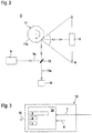
- Schematische Darstellung eines Ausführungsbeispiels der erfindungsgemäßen Überwachungsanordnung.
- Figur 2:
- Schematische Darstellung der Sensorkomponente eines Sensors für die Überwachungsanordnung gemäß
Figur 1 . - Figur 3:
- Schematische Darstellung der Steuereinheit eines Sensors für die Überwachungsanordnung gemäß
Figur 1 . -
Figur 1 zeigt schematisch ein Ausführungsbeispiel der erfindungsgemäßen Überwachungsanordnung 1. - Die Überwachungsanordnung 1 weist einen Sensor in Form eines optischen Sensors 2 mit einem Sensorelement 3 und einer Auswerteeinheit 4 auf. Der optische Sensor 2 ist im vorliegenden Fall als Sicherheitssensor ausgebildet. Hierzu weist die Auswerteeinheit 4 einen redundanten Aufbau auf, beispielsweise in Form zweier sich gegenseitig zyklisch überwachender Rechnereinheiten.
- Der optische Sensor 2 ist auf einem eine Anlage bildenden Fahrzeug 5 montiert, welches im vorliegenden Ausführungsbeispiel von einem spurgeführten Verschiebewagen gebildet ist. Alternativ kann das Fahrzeug 5 von einer Hängebahn, einem Regalbediengerät, einem Kran oder dergleichen gebildet sein.
- Die Fahrbahn ist seitlich von einer Fahrbahnbegrenzung 6, wie zum Beispiel einer Leitplanke, begrenzt. Auf der dem Fahrzeug 5 zugewandten Frontseite der Fahrbahnbegrenzung 6 ist ein Positionsmaßsystem 7 aufgebracht, welches eine Anordnung mit kooperativen Zielen ausbildet.
- Im vorliegenden Ausführungsbeispiel ist das Positionsmaßsystem 7 als Maßband ausgebildet, welches auf eine Unterlage aufgeklebt werden kann.
- Das Maßband besteht aus einer Folge von in Längsrichtung des Positionsmaßstabs 7 hintereinander angeordneten Marken in Form von Barcodes 8. Jeder Barcode 8 ist auf ein separates Segment des Maßbandes aufgebracht, wobei benachbarte Segmente jeweils durch eine Schneidelücke getrennt sind. Die Segmente weisen jeweils eine identische Breite auf. Die Breiten der Schneidelücken zwischen den einzelnen Segmenten sind ebenfalls konstant.
- Die einzelnen Segmente bilden somit identische Maßstabsmodule, so dass eine vorgegebene Länge des Maßbandes durch die Anzahl der Segmente multipliziert mit der Breite der Segmente und der Breite der jeweils anschließenden Schneidelücke vorgegeben ist. Die Segmente innerhalb des Maßbandes sind fortlaufend nummeriert, so dass jede Nummer eines Segments die Position innerhalb des Maßbandes kodiert. Die Nummer eines Segments ist in dem jeweiligen Barcode 8 kodiert.
- Mit von dem Sensorelement 3 des optischen Sensors 2 emittierten Sendelichtstrahlen 9a werden die Barcodes 8 des Positionsmaßsystems 7 bei der Vorbeifahrt des Fahrzeugs 5 nacheinander abgetastet und erfasst. In der Auswerteeinheit 4 erfolgt die Dekodierung der Barcodes 8. Dadurch wird mit dem optischen Sensor 2 fortlaufend die Position des Fahrzeugs 5 relativ zum Positionsmaßsystem 7 bestimmt. Aus der zeitlichen Folge der vom optischen Sensor 2 erfassten Signale kann auch die Geschwindigkeit des Fahrzeugs 5 bestimmt werden.
-
Figur 2 zeigt ein Ausführungsbeispiel der Sensorelemente 3 des optischen Sensors 2. Der optische Sensor 2 ist in diesem Fall als scannender Codeleser ausgebildet und umfasst einen Sendelichtstrahlen 9a emittierenden Sender 9 und einen Empfangslichtstrahlen 10a empfangenden Empfänger 10. Die vom Sender 9 emittierten Sendelichtstrahlen 9a und die von einem Barcode 8 zurückreflektierten Empfangslichtstrahlen 10a werden über eine Ablenkeinheit in Form eines mehrere spiegelnde Facetten 11a aufweisenden, um eine Drehachse drehbaren Polygonspiegelrads 11 geführt. Mittels eines Umlenkspiegels 12 wird eine koaxiale Strahlführung von Sendelichtstrahlen 9a und Empfangslichtstrahlen 10a erzielt. Durch die Drehbewegung des Polygonspiegelrads 11 werden die Sendelichtstrahlen 9a periodisch innerhalb eines Abtastbereichs A geführt. -
Figur 3 zeigt eine Steuereinheit 13 des Fahrzeugs 5 oder allgemein der Anlage. Mit der Steuereinheit 13 wird das Fahrzeug 5 in Abhängigkeit der mit dem optischen Sensor 2 erfassten Positionswerte gesteuert, insbesondere wird das Fahrzeug 5 an bestimmte Positionen entlang der Fahrbahn positioniert. - Die Steuereinheit 13 weist eine Speichereinheit 14, in der Kontrolldaten a manipulationssicher gespeichert sind. Die manipulationssichere Speicherung erfolgt mit einer Prüfsumme b. Im vorliegenden Fall sind den Kontrolldaten a Zuordnungsmerkmale c zugeordnet, die ebenfalls mit der Prüfsumme b abgesichert sind.
- Die Kontrolldaten a sind im einfachsten Fall direkt von den Objekterfassungsdaten des optischen Sensors 2 abgeleitet. Beispielsweise kann eine zeitliche Folge von ermittelten Positions- und/oder Geschwindigkeitswerten des Fahrzeugs 5, die mit dem optischen Sensor 2 ermittelt wurden, als Kontrolldaten a in der Speichereinheit 14 hinterlegt werden. Vorteilhaft sind diese Messwerte mit Zuordnungsmerkmalen c in Form von Zeitstempeln hinterlegt, so dass die Zeiten der Messwertgenerierung mit den Kontrolldaten a hinterlegt sind. Anstelle von Zeitstempeln können auch andere, die Kontrolldaten a kennzeichnende Zuordnungsmerkmale c vorgegeben werden, beispielsweise durch Benutzereingaben oder auch von der Steuereinheit 13 selbst.
- Anhand der gespeicherten Kontrolldaten a können in der Steuereinheit 13 Kontroll- und Überwachungsfunktionen durchgeführt werden. Beispielsweise können die die Kontrolldaten a bildenden Positions- und/oder Geschwindigkeitswerte mit vorgegebenen Sollwerten verglichen werden. Falls die Kontrolldaten a von den Sollwerten um ein vorgegebenes Maß abweichen, kann in der Steuereinheit 13 beispielsweise ein Nothalt des Fahrzeugs 5 ausgelöst werden.
- Weiterhin können aus den Kontrolldaten a in der Steuereinheit 13 Wartungsdaten für das Fahrzeug 5 abgeleitet werden. Hierzu werden die Objekterfassungsdaten des optischen Sensors 2 und gegebenenfalls externe Daten des Fahrzeugs 5 (gekennzeichnet mit dem Pfeil c) und interne Daten der Steuereinheit 13 (gekennzeichnet mit dem Pfeil d) in der Steuereinheit 13 ausgewertet, insbesondere um spezifische Anlagensituationen zu beschreiben oder zu analysieren. Beispielsweise kann mit den Kontrolldaten a eine Nothalt-Bremsung des Fahrzeug 5 als spezifische Anlagensituation erfasst werden, wobei hierzu neben den Positions- und Geschwindigkeitswerten des optischen Sensors 2 auch Fahrzeug-Parameter oder interne Steuerungsparameter zur Generierung der Wartungsdaten herangezogen werden.
- Derartige Wartungsdaten können beispielsweise den Bremsweg des Fahrzeugs 5 bei einem Bremsvorgang dokumentieren.
- Weiterhin können die Wartungsdaten dokumentieren, ob das Positionsmaßsystem 7 korrekt angeordnet ist oder ob dieses beschädigt ist.
- Die Kontrolldaten a, die in der Speichereinheit 14 abgespeichert sind, können über eine Schnittstelle 15 wie ein Bussystem an eine externe Einheit ausgelesen werden.
- Die externe Einheit kann beispielsweise ein Aufzeichnungsgerät sein, wo die Kontrolldaten a zu Dokumentationszwecken dauerhaft gespeichert werden. Alternativ können in der externen Einheit weitere Auswertungen der Kontrolldaten a erfolgen.
-
- (1)
- Überwachungsanordnung
- (2)
- Optischer Sensor
- (3)
- Sensorelement
- (4)
- Auswerteeinheit
- (5)
- Fahrzeug
- (6)
- Fahrbahnbegrenzung
- (7)
- Positionsmaßsystem
- (8)
- Barcode
- (9)
- Sender
- (9a)
- Sendelichtstrahlen
- (10)
- Empfänger
- (10a)
- Empfangslichtstrahlen
- (11)
- Polygonspiegelrad
- (11a)
- Facetten
- (12)
- Umlenkspiegel
- (13)
- Steuereinheit
- (14)
- Speichereinheit
- (15)
- Schnittstelle
- (A)
- Abtastbereich
- (a)
- Kontrolldaten
- (b)
- Prüfsumme
- (c)
- Zuordnungsmerkmal
Claims (17)
- Überwachungsanordnung (1) mit einem einer Anlage zugeordneten Sensor, wobei der Sensor wenigstens ein Sensorelement (3) und eine Auswerteeinheit (4) aufweist, wobei das Sensorelement (3) ausgebildet ist, Objekte innerhalb eines der Anlage zugeordneten Überwachungsbereichs zu erfassen und die Auswerteeinheit (4) ausgebildet ist, in Abhängigkeit von Sensorsignalen des Sensorelements (3) Objekterfassungsdaten zu generieren, dadurch gekennzeichnet, dass eine Speichereinheit (14) vorgesehen ist, in welcher in Abhängigkeit der Objekterfassungsdaten generierte Kontrolldaten (a) manipulationssicher abgespeichert sind.
- Überwachungsanordnung nach Anspruch 1, dadurch gekennzeichnet, dass mittels des Sensors kooperative Ziele erfassbar sind.
- Überwachungsanordnung nach einem der Ansprüche 1 oder 2, dadurch gekennzeichnet, dass der Sensor ein Distanzsensor ist.
- Überwachungsanordnung nach Anspruch 2, dadurch gekennzeichnet, dass die kooperativen Ziele von Marken eines Positionsmaßsystems (7) sind.
- Überwachungsanordnung nach Anspruch 4, dadurch gekennzeichnet, dass der Sensor ein Codeleser ist.
- Überwachungsanordnung nach einem der Ansprüche 1 bis 5, dadurch gekennzeichnet, dass die Anlage ein Fahrzeug (5), insbesondere ein fahrerloses Transportsystem ist.
- Überwachungsanordnung nach einem der Ansprüche 1 bis 6, dadurch gekennzeichnet, dass der Sensor mit der Anlage verbunden ist.
- Überwachungsanordnung nach einem der Ansprüche 2 bis 7, dadurch gekennzeichnet, dass die kooperativen Ziele stationär im Überwachungsbereich angeordnet sind.
- Überwachungsanordnung nach einem der Ansprüche 1 bis 8, dadurch gekennzeichnet, dass die Kontrolldaten (a) mittels einer Prüfsumme (b) manipulationssicher abgespeichert sind.
- Überwachungsanordnung nach einem der Ansprüche 1 bis 9, dadurch gekennzeichnet, dass die Kontrolldaten (a) mit wenigstens einem Zuordnungsmerkmal (c) abgespeichert sind.
- Überwachungsanordnung nach Anspruch 10, dadurch gekennzeichnet, dass die Zuordnungsmerkmale (c) durch Bedienereingaben oder selbsttätig durch die Anlage generiert sind.
- Überwachungsanordnung nach Anspruch 10, dadurch gekennzeichnet, dass die Zuordnungsmerkmale (c) von Zeitstempeln gebildet sind.
- Überwachungsanordnung nach einem der Ansprüche 9 bis 12, dadurch gekennzeichnet, dass die Kontrolldaten (a) mit den Zuordnungsmerkmalen (c) mittels einer Prüfsumme manipulationssicher abgespeichert sind.
- Überwachungsanordnung nach einem der Ansprüche 1 bis 13, dadurch gekennzeichnet, dass die Speichereinheit (14) in einer Steuereinheit (13) der Anlage integriert ist.
- Überwachungsanordnung nach einem der Ansprüche 1 bis 14, dadurch gekennzeichnet, dass die Kontrolldaten (a) Wartungsdaten sind oder dass die Wartungsdaten durch eine Auswertung der Kontrolldaten (a) gewonnen sind.
- Überwachungsanordnung nach Anspruch 15, dadurch gekennzeichnet, dass mit den Wartungsdaten ein Bremsweg eines Fahrzeugs (5) oder der Zustand eines Positionsmaßsystems (7) dokumentiert ist.
- Überwachungsanordnung nach Anspruch 15, dadurch gekennzeichnet, dass die Kontrolldaten (a) oder Wartungsdaten in einer externen Einheit ausgewertet und/oder aufgezeichnet werden.
Priority Applications (1)
| Application Number | Priority Date | Filing Date | Title |
|---|---|---|---|
| EP17157309.0A EP3367128B1 (de) | 2017-02-22 | 2017-02-22 | Überwachungsanordnung |
Applications Claiming Priority (1)
| Application Number | Priority Date | Filing Date | Title |
|---|---|---|---|
| EP17157309.0A EP3367128B1 (de) | 2017-02-22 | 2017-02-22 | Überwachungsanordnung |
Publications (2)
| Publication Number | Publication Date |
|---|---|
| EP3367128A1 true EP3367128A1 (de) | 2018-08-29 |
| EP3367128B1 EP3367128B1 (de) | 2020-10-28 |
Family
ID=58192103
Family Applications (1)
| Application Number | Title | Priority Date | Filing Date |
|---|---|---|---|
| EP17157309.0A Active EP3367128B1 (de) | 2017-02-22 | 2017-02-22 | Überwachungsanordnung |
Country Status (1)
| Country | Link |
|---|---|
| EP (1) | EP3367128B1 (de) |
Cited By (3)
| Publication number | Priority date | Publication date | Assignee | Title |
|---|---|---|---|---|
| CN114966606A (zh) * | 2021-02-19 | 2022-08-30 | 西克股份公司 | 光电安全装置 |
| EP4403881A1 (de) * | 2023-01-19 | 2024-07-24 | Leuze electronic GmbH + Co. KG | Sensoranordnung und verfahren zum betrieb einer sensoranordnung |
| DE202024104318U1 (de) * | 2024-08-01 | 2025-11-20 | Leuze Electronic Gmbh + Co. Kg | Sensoranordnung |
Citations (4)
| Publication number | Priority date | Publication date | Assignee | Title |
|---|---|---|---|---|
| US4901073A (en) * | 1986-12-04 | 1990-02-13 | Regent Of The University Of California | Encoder for measuring the absolute position of moving elements |
| EP1345031A2 (de) * | 2002-03-16 | 2003-09-17 | Leuze electronic GmbH + Co. | Optoelektronische Vorrichtung |
| DE102006025045A1 (de) * | 2006-05-30 | 2007-12-06 | Leuze Electronic Gmbh + Co. Kg | Optoelektronische Vorrichtung |
| US20170018188A1 (en) * | 2014-04-28 | 2017-01-19 | Hitachi Construction Machinery Co., Ltd. | Road shoulder-detecting system and transportation vehicle for mining |
-
2017
- 2017-02-22 EP EP17157309.0A patent/EP3367128B1/de active Active
Patent Citations (5)
| Publication number | Priority date | Publication date | Assignee | Title |
|---|---|---|---|---|
| US4901073A (en) * | 1986-12-04 | 1990-02-13 | Regent Of The University Of California | Encoder for measuring the absolute position of moving elements |
| EP1345031A2 (de) * | 2002-03-16 | 2003-09-17 | Leuze electronic GmbH + Co. | Optoelektronische Vorrichtung |
| DE10211779B4 (de) | 2002-03-16 | 2005-03-31 | Leuze Electronic Gmbh & Co Kg | Optoelektronische Vorrichtung |
| DE102006025045A1 (de) * | 2006-05-30 | 2007-12-06 | Leuze Electronic Gmbh + Co. Kg | Optoelektronische Vorrichtung |
| US20170018188A1 (en) * | 2014-04-28 | 2017-01-19 | Hitachi Construction Machinery Co., Ltd. | Road shoulder-detecting system and transportation vehicle for mining |
Cited By (4)
| Publication number | Priority date | Publication date | Assignee | Title |
|---|---|---|---|---|
| CN114966606A (zh) * | 2021-02-19 | 2022-08-30 | 西克股份公司 | 光电安全装置 |
| EP4403881A1 (de) * | 2023-01-19 | 2024-07-24 | Leuze electronic GmbH + Co. KG | Sensoranordnung und verfahren zum betrieb einer sensoranordnung |
| DE202024104318U1 (de) * | 2024-08-01 | 2025-11-20 | Leuze Electronic Gmbh + Co. Kg | Sensoranordnung |
| EP4686915A1 (de) * | 2024-08-01 | 2026-02-04 | Leuze electronic GmbH + Co. KG | Sensoranordnung |
Also Published As
| Publication number | Publication date |
|---|---|
| EP3367128B1 (de) | 2020-10-28 |
Similar Documents
| Publication | Publication Date | Title |
|---|---|---|
| EP2728305B1 (de) | Verfahren und Lichtmuster zum Messen der Höhe oder des Höhenverlaufs eines Objekts | |
| DE10312972B3 (de) | Optischer Sensor | |
| WO2009000727A1 (de) | Optischer sensor für positionieraufgaben | |
| EP1788467A2 (de) | Schutzeinrichtung | |
| EP3587894B1 (de) | Sensoranordnung und verfahren zum betrieb einer sensoranordnung | |
| DE10211779B4 (de) | Optoelektronische Vorrichtung | |
| EP3401702B1 (de) | Sensorsystem | |
| EP3367128B1 (de) | Überwachungsanordnung | |
| EP3270114B1 (de) | Sensoranordnung | |
| EP3418846A1 (de) | Vorrichtung zur sicherheitssteuerung einer maschine | |
| EP3882505B1 (de) | Überwachungseinrichtung und ein verfahren zum betrieb einer überwachungseinrichtung | |
| DE102020113183B4 (de) | Kamera und Verfahren zur Erfassung von bewegten Objekten | |
| DE102005047658B4 (de) | Vorrichtung zur Positionsbestimmung | |
| DE102006053002B4 (de) | Optischer Sensor | |
| EP2306145B1 (de) | Optischer Sensor | |
| DE102008032786A1 (de) | Vorrichtung und Verfahren zum Bestimmen einer Position eines Fahrzeugs | |
| EP2636998B1 (de) | Messwertgeber zum Erhalt einer Positionsinformation und Verfahren zu dessen Betrieb | |
| EP3399336B1 (de) | Positioniervorrichtung | |
| EP4279946A1 (de) | Sensor und verfahren zur detektion von objekten mittels eines sensors | |
| EP3588130B1 (de) | Optischer sensor | |
| EP4403881A1 (de) | Sensoranordnung und verfahren zum betrieb einer sensoranordnung | |
| EP3671289A1 (de) | Sensoranordnung | |
| DE4424008C2 (de) | Optoelektronische Vorrichtung zum Erkennen von Marken | |
| DE102024131596B3 (de) | Vorrichtung und Verfahren zur Bestimmung einer Position | |
| DE202014101714U1 (de) | Codelesesystem zum Lesen von Codes |
Legal Events
| Date | Code | Title | Description |
|---|---|---|---|
| PUAI | Public reference made under article 153(3) epc to a published international application that has entered the european phase |
Free format text: ORIGINAL CODE: 0009012 |
|
| STAA | Information on the status of an ep patent application or granted ep patent |
Free format text: STATUS: REQUEST FOR EXAMINATION WAS MADE |
|
| 17P | Request for examination filed |
Effective date: 20171020 |
|
| AK | Designated contracting states |
Kind code of ref document: A1 Designated state(s): AL AT BE BG CH CY CZ DE DK EE ES FI FR GB GR HR HU IE IS IT LI LT LU LV MC MK MT NL NO PL PT RO RS SE SI SK SM TR |
|
| AX | Request for extension of the european patent |
Extension state: BA ME |
|
| GRAP | Despatch of communication of intention to grant a patent |
Free format text: ORIGINAL CODE: EPIDOSNIGR1 |
|
| STAA | Information on the status of an ep patent application or granted ep patent |
Free format text: STATUS: GRANT OF PATENT IS INTENDED |
|
| GRAS | Grant fee paid |
Free format text: ORIGINAL CODE: EPIDOSNIGR3 |
|
| GRAA | (expected) grant |
Free format text: ORIGINAL CODE: 0009210 |
|
| STAA | Information on the status of an ep patent application or granted ep patent |
Free format text: STATUS: THE PATENT HAS BEEN GRANTED |
|
| INTG | Intention to grant announced |
Effective date: 20200903 |
|
| AK | Designated contracting states |
Kind code of ref document: B1 Designated state(s): DE |
|
| RBV | Designated contracting states (corrected) |
Designated state(s): DE |
|
| REG | Reference to a national code |
Ref country code: DE Ref legal event code: R096 Ref document number: 502017007893 Country of ref document: DE |
|
| REG | Reference to a national code |
Ref country code: DE Ref legal event code: R097 Ref document number: 502017007893 Country of ref document: DE |
|
| PLBE | No opposition filed within time limit |
Free format text: ORIGINAL CODE: 0009261 |
|
| STAA | Information on the status of an ep patent application or granted ep patent |
Free format text: STATUS: NO OPPOSITION FILED WITHIN TIME LIMIT |
|
| 26N | No opposition filed |
Effective date: 20210729 |
|
| P01 | Opt-out of the competence of the unified patent court (upc) registered |
Free format text: CASE NUMBER: UPC_APP_0013915_3367128/2025 Effective date: 20251119 |
|
| PGFP | Annual fee paid to national office [announced via postgrant information from national office to epo] |
Ref country code: DE Payment date: 20260218 Year of fee payment: 10 |