EP3671289A1 - Sensoranordnung - Google Patents
Sensoranordnung Download PDFInfo
- Publication number
- EP3671289A1 EP3671289A1 EP18215649.7A EP18215649A EP3671289A1 EP 3671289 A1 EP3671289 A1 EP 3671289A1 EP 18215649 A EP18215649 A EP 18215649A EP 3671289 A1 EP3671289 A1 EP 3671289A1
- Authority
- EP
- European Patent Office
- Prior art keywords
- sensor
- contour detection
- field
- transfer object
- detection field
- Prior art date
- Legal status (The legal status is an assumption and is not a legal conclusion. Google has not performed a legal analysis and makes no representation as to the accuracy of the status listed.)
- Granted
Links
Images

Classifications
-
- G—PHYSICS
- G01—MEASURING; TESTING
- G01V—GEOPHYSICS; GRAVITATIONAL MEASUREMENTS; DETECTING MASSES OR OBJECTS; TAGS
- G01V8/00—Prospecting or detecting by optical means
- G01V8/10—Detecting, e.g. by using light barriers
- G01V8/12—Detecting, e.g. by using light barriers using one transmitter and one receiver
- G01V8/18—Detecting, e.g. by using light barriers using one transmitter and one receiver using mechanical scanning systems
-
- F—MECHANICAL ENGINEERING; LIGHTING; HEATING; WEAPONS; BLASTING
- F16—ENGINEERING ELEMENTS AND UNITS; GENERAL MEASURES FOR PRODUCING AND MAINTAINING EFFECTIVE FUNCTIONING OF MACHINES OR INSTALLATIONS; THERMAL INSULATION IN GENERAL
- F16P—SAFETY DEVICES IN GENERAL; SAFETY DEVICES FOR PRESSES
- F16P3/00—Safety devices acting in conjunction with the control or operation of a machine; Control arrangements requiring the simultaneous use of two or more parts of the body
- F16P3/12—Safety devices acting in conjunction with the control or operation of a machine; Control arrangements requiring the simultaneous use of two or more parts of the body with means, e.g. feelers, which in case of the presence of a body part of a person in or near the danger zone influence the control or operation of the machine
- F16P3/14—Safety devices acting in conjunction with the control or operation of a machine; Control arrangements requiring the simultaneous use of two or more parts of the body with means, e.g. feelers, which in case of the presence of a body part of a person in or near the danger zone influence the control or operation of the machine the means being photocells or other devices sensitive without mechanical contact
- F16P3/144—Safety devices acting in conjunction with the control or operation of a machine; Control arrangements requiring the simultaneous use of two or more parts of the body with means, e.g. feelers, which in case of the presence of a body part of a person in or near the danger zone influence the control or operation of the machine the means being photocells or other devices sensitive without mechanical contact using light grids
-
- G—PHYSICS
- G01—MEASURING; TESTING
- G01S—RADIO DIRECTION-FINDING; RADIO NAVIGATION; DETERMINING DISTANCE OR VELOCITY BY USE OF RADIO WAVES; LOCATING OR PRESENCE-DETECTING BY USE OF THE REFLECTION OR RERADIATION OF RADIO WAVES; ANALOGOUS ARRANGEMENTS USING OTHER WAVES
- G01S17/00—Systems using the reflection or reradiation of electromagnetic waves other than radio waves, e.g. lidar systems
- G01S17/02—Systems using the reflection of electromagnetic waves other than radio waves
- G01S17/04—Systems determining the presence of a target
-
- G—PHYSICS
- G01—MEASURING; TESTING
- G01S—RADIO DIRECTION-FINDING; RADIO NAVIGATION; DETERMINING DISTANCE OR VELOCITY BY USE OF RADIO WAVES; LOCATING OR PRESENCE-DETECTING BY USE OF THE REFLECTION OR RERADIATION OF RADIO WAVES; ANALOGOUS ARRANGEMENTS USING OTHER WAVES
- G01S17/00—Systems using the reflection or reradiation of electromagnetic waves other than radio waves, e.g. lidar systems
- G01S17/02—Systems using the reflection of electromagnetic waves other than radio waves
- G01S17/06—Systems determining position data of a target
- G01S17/08—Systems determining position data of a target for measuring distance only
- G01S17/10—Systems determining position data of a target for measuring distance only using transmission of interrupted, pulse-modulated waves
-
- F—MECHANICAL ENGINEERING; LIGHTING; HEATING; WEAPONS; BLASTING
- F16—ENGINEERING ELEMENTS AND UNITS; GENERAL MEASURES FOR PRODUCING AND MAINTAINING EFFECTIVE FUNCTIONING OF MACHINES OR INSTALLATIONS; THERMAL INSULATION IN GENERAL
- F16P—SAFETY DEVICES IN GENERAL; SAFETY DEVICES FOR PRESSES
- F16P3/00—Safety devices acting in conjunction with the control or operation of a machine; Control arrangements requiring the simultaneous use of two or more parts of the body
- F16P3/12—Safety devices acting in conjunction with the control or operation of a machine; Control arrangements requiring the simultaneous use of two or more parts of the body with means, e.g. feelers, which in case of the presence of a body part of a person in or near the danger zone influence the control or operation of the machine
- F16P3/14—Safety devices acting in conjunction with the control or operation of a machine; Control arrangements requiring the simultaneous use of two or more parts of the body with means, e.g. feelers, which in case of the presence of a body part of a person in or near the danger zone influence the control or operation of the machine the means being photocells or other devices sensitive without mechanical contact
- F16P3/141—Safety devices acting in conjunction with the control or operation of a machine; Control arrangements requiring the simultaneous use of two or more parts of the body with means, e.g. feelers, which in case of the presence of a body part of a person in or near the danger zone influence the control or operation of the machine the means being photocells or other devices sensitive without mechanical contact using sound propagation, e.g. sonar
-
- F—MECHANICAL ENGINEERING; LIGHTING; HEATING; WEAPONS; BLASTING
- F16—ENGINEERING ELEMENTS AND UNITS; GENERAL MEASURES FOR PRODUCING AND MAINTAINING EFFECTIVE FUNCTIONING OF MACHINES OR INSTALLATIONS; THERMAL INSULATION IN GENERAL
- F16P—SAFETY DEVICES IN GENERAL; SAFETY DEVICES FOR PRESSES
- F16P3/00—Safety devices acting in conjunction with the control or operation of a machine; Control arrangements requiring the simultaneous use of two or more parts of the body
- F16P3/12—Safety devices acting in conjunction with the control or operation of a machine; Control arrangements requiring the simultaneous use of two or more parts of the body with means, e.g. feelers, which in case of the presence of a body part of a person in or near the danger zone influence the control or operation of the machine
- F16P3/14—Safety devices acting in conjunction with the control or operation of a machine; Control arrangements requiring the simultaneous use of two or more parts of the body with means, e.g. feelers, which in case of the presence of a body part of a person in or near the danger zone influence the control or operation of the machine the means being photocells or other devices sensitive without mechanical contact
- F16P3/142—Safety devices acting in conjunction with the control or operation of a machine; Control arrangements requiring the simultaneous use of two or more parts of the body with means, e.g. feelers, which in case of the presence of a body part of a person in or near the danger zone influence the control or operation of the machine the means being photocells or other devices sensitive without mechanical contact using image capturing devices
-
- F—MECHANICAL ENGINEERING; LIGHTING; HEATING; WEAPONS; BLASTING
- F16—ENGINEERING ELEMENTS AND UNITS; GENERAL MEASURES FOR PRODUCING AND MAINTAINING EFFECTIVE FUNCTIONING OF MACHINES OR INSTALLATIONS; THERMAL INSULATION IN GENERAL
- F16P—SAFETY DEVICES IN GENERAL; SAFETY DEVICES FOR PRESSES
- F16P3/00—Safety devices acting in conjunction with the control or operation of a machine; Control arrangements requiring the simultaneous use of two or more parts of the body
- F16P3/12—Safety devices acting in conjunction with the control or operation of a machine; Control arrangements requiring the simultaneous use of two or more parts of the body with means, e.g. feelers, which in case of the presence of a body part of a person in or near the danger zone influence the control or operation of the machine
- F16P3/14—Safety devices acting in conjunction with the control or operation of a machine; Control arrangements requiring the simultaneous use of two or more parts of the body with means, e.g. feelers, which in case of the presence of a body part of a person in or near the danger zone influence the control or operation of the machine the means being photocells or other devices sensitive without mechanical contact
- F16P3/147—Safety devices acting in conjunction with the control or operation of a machine; Control arrangements requiring the simultaneous use of two or more parts of the body with means, e.g. feelers, which in case of the presence of a body part of a person in or near the danger zone influence the control or operation of the machine the means being photocells or other devices sensitive without mechanical contact using electro-magnetic technology, e.g. tags or radar
-
- G—PHYSICS
- G01—MEASURING; TESTING
- G01V—GEOPHYSICS; GRAVITATIONAL MEASUREMENTS; DETECTING MASSES OR OBJECTS; TAGS
- G01V8/00—Prospecting or detecting by optical means
- G01V8/10—Detecting, e.g. by using light barriers
- G01V8/12—Detecting, e.g. by using light barriers using one transmitter and one receiver
- G01V8/14—Detecting, e.g. by using light barriers using one transmitter and one receiver using reflectors
Definitions
- the invention relates to a sensor arrangement and a method for operating a sensor arrangement.
- Such sensor arrangements generally include an optical sensor, which can be designed in particular as an area distance sensor.
- a surface distance sensor typically has a distance sensor with a light beam emitting transmitter and a light beam receiving receiver.
- the light rays of the transmitter are periodically deflected into an angular range and thus scan a monitoring area in individual scans.
- optical sensors are typically used in the field of security technology and are therefore used as security sensors, i. H. designed as sensors with a fail-safe structure.
- optical sensor One area of application of such an optical sensor is the danger zone monitoring in a dangerous system.
- a protective field is stored in the optical sensor, which is adapted to the hazardous area of the system.
- the optical sensor then performs object detection such that, depending on whether an object is detected in the protective field or not, a binary object detection signal is generated, the switching states of which indicate whether an object is in the protective field or not. If an object is detected in the protective field and a corresponding object detection signal is generated, a safety function is triggered in such a way that the system is shut down.
- the invention has for its object to provide a sensor arrangement of the type mentioned, which has a high functionality with low design effort.
- the invention relates to a sensor arrangement with at least one sensor for detecting objects in a monitoring area.
- the sensor is designed to track a transfer object moving along a defined, predetermined path curve.
- a contour detection field and a monitoring protection field are activated in the sensor depending on the position of the transfer object.
- the contour detection field is the surveillance protection field in the direction upstream of the transfer object and the transfer object is left out of the monitoring protection field.
- the sensor triggers a safety function when an object enters the monitoring protection field.
- the invention further relates to a method for operating a sensor arrangement.
- the sensor of the sensor arrangement according to the invention can in principle be designed as a radar sensor or as an ultrasonic sensor.
- the sensor is particularly advantageously designed as an optical sensor. Without restricting generality, reference is made below to sensors in the form of optical sensors.
- the sensor arrangement according to the invention is preferably used in the field of security technology, with the optical sensor serving as a security sensor, i. H. Sensor is designed with a fail-safe structure.
- a controller is assigned to the optical sensor, which is designed as a safety controller to meet the requirements for use in the field of safety technology.
- the main advantage of the sensor arrangement according to the invention is that danger zone monitoring is carried out with only one optical sensor in such a way that a safety function is triggered when an object intervention in a monitoring protection field is detected with the optical sensor, and that at the same time with the optical sensor Tracking a transfer object, such as B. a vehicle is made possible in such a way that the detection of the transfer object with the optical sensor does not lead to the triggering of a safety function.
- the sensor arrangement is particularly suitable for use in access control systems.
- a transfer object in particular a vehicle, is moved along a certain path curve to an access to a system or the like.
- a contour detection field and a monitoring protection field adapted to it are specified in the optical sensor.
- the contour detection field is upstream of the monitoring protection field in the direction of the transfer object, i. H. the contour detection field leads the surveillance protection field from the point of view of the optical sensor.
- the shapes and the sequence of the contour detection field are advantageously designed such that only the transfer object can interrupt the contour detection field.
- the surveillance protection field is generally designed in such a way that it omits the transfer object, otherwise the surveillance protection field can have any shape.
- the transfer object moves along a predetermined path curve, the speed of the transfer object being advantageous, but not necessarily constant.
- a contour detection field and a monitoring protection field are stored in the optical sensor for the individual positions of the transfer object.
- the transfer object is detected with the currently active contour detection field.
- Other dangerous objects are detected in the monitoring protection field.
- the entire danger area in front of and to the side of the transfer object can be monitored by object detections in the surveillance protection field by means of the optical sensor during the entire journey of the transfer object, and if an object enters the surveillance protection field, the optical sensor provides a suitable safety function such as a stop command for a system or the submission of a fault report generated.
- a suitable safety function such as a stop command for a system or the submission of a fault report generated.
- the transfer object moves along a predetermined path, the transfer object is always outside the monitoring protection field, so that detections of the transfer object by means of the optical sensor do not lead to an unnecessary triggering of the safety function.
- the transfer object can penetrate into the monitoring protective field, so that the optical sensor triggers the safety function.
- a sequence of pairs of contour detection fields and monitoring protection fields is stored in the optical sensor. Depending on the current position of the transfer object, a contour detection field and an assigned monitoring protection field are activated.
- the appropriate pair of a contour detection field and monitoring protection field is activated from the sequence of the stored pairs of contour detection field and monitoring protection field for the current position of the transfer object.
- the activation could take place automatically in the optical sensor in a predetermined time grid. Activation can also take place via the safety controller.
- a switchover to a new contour detection field and a monitoring protection field assigned to the new contour detection field is particularly advantageous.
- Switching can take place in the optical sensor itself.
- the switchover in the safety controller is particularly advantageous.
- the safety controller generates corresponding output signals that are read into the optical sensor.
- the safety controller processes output signals of the optical sensor for the contour detection field and the monitoring protection field, which are each output to the safety controller via a safe output of the optical sensor.
- a switch to a new contour detection field only takes place if an object intervention is registered only in the currently activated contour detection field, but not in the currently defined surveillance protection field.
- the changeover of the contour detection field and thus the monitoring protection field is thus event-controlled in that the current contour detection field itself is violated by the transfer object itself after a certain period of time as a result of the movement of the transfer object. Since the next contour detection field is activated with a new monitoring protection field after violation of the current contour detection field, it is ensured that the monitoring protection field is not violated by the transfer object, so that the safety function is not triggered unnecessarily.
- positions, sizes and / or contours of objects in the contour recognition field are determined with the sensor as measurement data, and that a switch to a new contour recognition field only takes place when the transfer object is recognized on the basis of the measurement data.
- the contour detection field ensures that only the transfer object can interrupt the contour detection field and not other objects that are in the vicinity of the transfer object. Rather, these other objects are detected in the surveillance protection field, which triggers the safety function.
- the transfer object can thus be clearly distinguished from other objects.
- the chronological sequence of switching over of contour detection fields is monitored in the optical sensor or in the safety controller.
- the currently determined chronological sequence of switchovers is compared with a target sequence. If the time sequence deviates from the target sequence, an initial value of the contour detection field and the associated monitoring protection field is activated.
- This provides an additional safety function in that uncontrolled deviations from the specified trajectory are recognized themselves, with countermeasures being initiated in the event of a detected deviation, which avoid unsafe conditions. If, after resetting the contour detection field to the initial value, the transfer object is recognized in the current monitoring protection field, the optical sensor triggers the safety function.
- part of the contour detection field can be provided with a so-called reference contour.
- a reference contour defines a tolerance band around a part of the contour detection field. The output belonging to the contour detection field only switches on if the measured values are within the tolerance band over the entire range of the reference contour. In this way, the contour detection field can be adapted to the geometry of the transfer object, so that it is not possible to switch contour detection fields with other objects.
- the transfer object is identified with a marking object. Switching to a new contour detection field only takes place if the marking object is detected with the sensor.
- the marking object advantageously differs from the rest of the surface of the transfer object and can thus be clearly detected with the sensor.
- the marking object is formed by a reflector.
- the sensor can determine the position of the marking object.
- the marking object, in particular the reflector is recognized on the basis of the signal strengths registered in the sensor at the receiving end.
- a sensor unit is integrated in the transfer object, by means of which the position of the transfer object is determined for the transfer object by detecting markings on a roadway becomes.
- the contour detection field and monitoring protection field are switched depending on the positions.
- the markings can be designed as optical markings, barcodes, QR codes, RFID tags or the like.
- the signals generated by the sensor unit are fed to the sensor or the control, where the changeover of the contour detection field and monitoring protection field can then take place.
- a distance sensor for determining the position of the transfer object, the switching between contour detection field and monitoring protection field taking place as a function of distance values of the distance sensor.
- the signals from the distance sensor are fed to the sensor or the control, where the changeover of the contour detection field and monitoring protection field can then take place.
- the sensor arrangement has means for monitoring the position of the optical sensor.
- the reference object has a reference object arranged stationary outside the optical sensor. With the optical sensor, the reference object is recorded in a spatially resolved manner for monitoring a position.
- the reference object advantageously has a characteristic shape or structure, so that it can be clearly distinguished from other objects in the optical sensor.
- Manipulations can be detected in such a way that the position of the optical sensor is changed. This is necessary because the optical Sensor-stored contour detection fields and monitoring protection fields are related to a defined mounting position of the optical sensor, which must therefore be strictly observed.
- the function of the optical sensor is generally such that a binary object detection signal is generated depending on an object detection in the monitoring protection field.
- the switching states of the object detection signal indicate whether an object is in the monitoring protection field or not. If an object detection signal is generated, the switching status of which signals an object in the monitoring protection field, the safety function is triggered.
- the optical sensor can be designed as a 2D camera or 3D camera. Two or three-dimensional distance images can thus be recorded with the camera.
- the optical sensor is a scanning distance sensor.
- a three-dimensional spatial area can be imaged with such a scanning distance sensor. Furthermore, only a flat area can be scanned. In this case, the optical sensor forms an area distance sensor.
- Such an area distance sensor has a distance sensor with a transmitter and receiver.
- the light rays from the transmitter are periodically guided in a flat monitoring area.
- the light beams of the transmitter are deflected with a deflection unit or the distance sensor is integrated in a rotating measuring head.
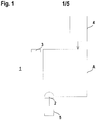
- Figure 1 schematically shows an embodiment of the sensor arrangement 1 according to the invention, which has an optical sensor 2 and an assigned reference object 3 as essential components.
- a danger zone A is secured with the optical sensor 2.
- the optical sensor 2 is connected to a safety controller 5.
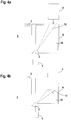
- Figure 2 shows an optical sensor 2 in the form of an area distance sensor.
- the surface distance sensor has a distance sensor arranged in a stationary manner in a housing 2a, with a transmitter 7 emitting light rays 6 and a receiver 8 receiving light rays 6.
- the transmitter 7 is formed, for example, by a laser diode, the receiver 8 by an APD (avalanche photodiode).
- the distances of objects 9 are determined, for example according to a pulse transit time method, for which purpose the transmitter 7 emits light beams 6 in the form of light pulses.
- the light rays 6 emitted by the transmitter 7 as well as the light rays 6 reflected back by an object 9 to be detected are guided over a mirror surface 10a of a deflection unit 10.
- the light beams 6 are deflected in an angular range by the rotary movement of the motor-driven deflection unit 10 about an axis of rotation D.
- positions of objects 9, in particular within a protective field can be detected.
- Figure 3 shows a variant of the area distance sensor according to Figure 2 .
- the area distance sensor according to Figure 3 differs from the area distance sensor according to Figure 2 in that the transmitter 7 and receiver 8 of the distance sensor are mounted in a measuring head 12 mounted on a base 11 and rotatable about an axis of rotation D.
- the optical sensor 2 has an evaluation unit (not shown) in which the positions of objects 9 are determined from the received signals of the receiver 8 and the current deflection positions of the light beams 6.
- the optical sensor 2 is designed as a security scanner.
- the evaluation unit has a fail-safe redundant structure, preferably in the form of two mutually cyclically monitoring computing units.
- the optical sensor 2 is designed such that it can be used to detect objects 9 in the entire danger area A.
- the optical sensor 2 is arranged stationary in a target position at an edge of the danger area A.
- the setpoint position of the optical sensor 2 is checked in that it periodically detects the reference object 3, which is stationary on the opposite edge of the danger area A or generally outside the danger area A.
- the reference object 3 has a characteristic geometry or structure and can thus be clearly distinguished from other objects 9. If the reference object 3 is recognized by the optical sensor 2 in a desired position, the optical sensor 2 is correctly mounted. If this is not the case, the optical sensor 2 issues a fault message.
- the transfer object 4 moves along a predetermined path curve, in particular at a constant speed, along a straight path through the danger area A.
- a contour detection field 13 and a monitoring protection field 14 are activated in the optical sensor 2 as a function of time.
- this switchover can also take place by the transfer object 4 penetrating into the contour detection field 13.
- the contour detection field 13 leads the monitoring protection field 14 from the viewpoint of the optical sensor 2, the contour detection field 13 being wedge-shaped. With the front edge of the contour detection field 13 running along a straight line, part of the front of the transfer object 4 can be recognized.
- the monitoring protection field 14 is always designed in such a way that it omits the transfer object 4. Otherwise, the contour of the monitoring protective field 14 can be selected as desired.
- a contour detection field 13 adapted for this purpose and, depending on this, a monitoring protection field 14 are activated.
- the entirety of all pairs of contour detection fields 13 and monitoring protection fields 14 is stored in the evaluation unit of the optical sensor 2.
- a suitable pair of a contour detection field 13 and a monitoring protection field 14 are activated.
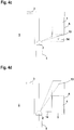
- the Figures 4a to 4d show the activated contour detection field 13 and the activated monitoring protection field 14 for different positions.
- the transfer object 4 is located outside the danger area A, so that the activated monitoring protective field 14 can extend over the entire danger area A.
- the wedge-shaped contour detection field 13 is adapted to the trajectory of the transfer object 4.
- the Figures 4b to 4d show the transfer object 4 when crossing the danger zone A.
- the respectively activated contour detection field 13 is dimensioned such that a part of the front of the transfer object 4 can be detected with it.
- the respectively activated monitoring protection field 14 is adapted to the contour of the transfer object 4 in such a way that the transfer object 4 is omitted from the monitoring protection field 14. If the transfer object 4 has reached the edge of the danger area A, the contour detection field 13 jumps back to its starting position ( Figure 4d ).
- the function of the optical sensor 2 is such that, depending on whether an object 9 is detected in the current monitoring protection field 14 or not, a binary object detection signal is generated, the switching states of which indicate whether an object 9 is located in the monitoring protection field 14 or not. If the optical sensor 2 indicates an object detection signal with the switching state "object present in the monitoring protection field", a safety function is triggered, for example in the safety controller 5.
- the safety function can be a fault message or a stop command for a system.
- the respectively activated monitoring protection field 14 is adjusted such that the transfer object 4 is not in the fault-free case protrudes into the monitoring protection field 14 and thus does not trigger a safety function.
- the transfer object 4 can thus pass through the danger area A unhindered.
- the adaptation of the contour detection field 13 and the monitoring protection field 14 takes place on the basis of the sequences of the contour detection protection field 13 and monitoring protection field 14 stored in the optical sensor 2 by switching processes.
- the switching operations are carried out by the safety controller 5. In principle, the switching could also take place in the optical sensor 2.
- Figure 4c shows the currently activated contour detection field 13 and the currently activated monitoring protection field 14 when the transfer object 4 is completely moved into the danger area A.
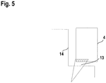
- the transfer object 4 continues to move in a uniform manner and then injures, as in FIG Figure 5 shown with the area highlighted with dashed lines, the contour detection field 13, ie the transfer object 4 penetrates into the contour detection field 13.
- the contour detection field 13 and the monitoring protection field 14 are continuously adapted to the current position, so that the currently activated monitoring protection field 14 always omits the transfer object 4.
- contour detection field 13 were not, as in Figure 5 represented, covered by the transfer object 4 but by another object 9, would be the Protective field switchover interrupted, object 9 would then have entered monitoring protective field 14 and optical sensor 2 would have triggered the safety function.
- the safety controller 5 monitors the chronological sequence of changes in the contour detection fields 13 and thus monitors the chronological sequence of the activation of the contour detection fields 13 and the associated monitoring protection fields 14 optical sensor 2 is known and stored. From this, a chronological target sequence of activated contour detection fields 13 is derived, which is stored in the optical sensor 2. The current sequence of activation of contour detection fields 13 is then compared with the target sequence. If deviations of the current sequence from the target sequence are registered, for example due to incorrect operation of the transfer object 4, which leads to sudden changes in direction or speed, the contour detection field 13 in the optical sensor 2 is reset to its initial value (corresponding to that in FIG Figure 4a configuration shown). If the transfer object 4 is then still in the danger zone A and thus in the newly activated monitoring protection field 14, the optical sensor 2 generates an object detection signal which leads to the triggering of the safety function.
- the contour detection field 13 can be provided with a reference contour which is adapted to the contour of the transfer object 4.
- a reference contour all measured values must be within a tolerance band over the entire area of the reference contour. Only if this is the case does the optical sensor 2 switch on its output, which is assigned to the contour detection field 13. This makes it possible to distinguish between the transfer object 4 and another object 9.
Landscapes
- Physics & Mathematics (AREA)
- Engineering & Computer Science (AREA)
- Electromagnetism (AREA)
- General Physics & Mathematics (AREA)
- Remote Sensing (AREA)
- Radar, Positioning & Navigation (AREA)
- Computer Networks & Wireless Communication (AREA)
- General Engineering & Computer Science (AREA)
- Life Sciences & Earth Sciences (AREA)
- General Life Sciences & Earth Sciences (AREA)
- Geophysics (AREA)
- Mechanical Engineering (AREA)
- Optical Radar Systems And Details Thereof (AREA)
- Geophysics And Detection Of Objects (AREA)
Abstract
Description
- Die Erfindung betrifft eine Sensoranordnung und ein Verfahren zum Betrieb einer Sensoranordnung.
- Derartige Sensoranordnungen umfassen generell einen optischen Sensor, der insbesondere als Flächendistanzsensor ausgebildet sein kann.
- Ein Flächendistanzsensor weist typischerweise einen Distanzsensor mit einem Lichtstrahlen emittierenden Sender und einem Lichtstrahlen empfangenden Empfänger auf. Die Lichtstrahlen des Senders werden periodisch in einen Winkelbereich abgelenkt und tasten so in einzelnen Scans einen Überwachungsbereich ab.
- Derartige optische Sensoren werden typischerweise im Bereich der Sicherheitstechnik eingesetzt und sind daher als Sicherheitssensoren, d. h. als Sensoren mit einem fehlersicheren Aufbau ausgebildet.
- Ein Anwendungsbereich eines solchen optischen Sensors ist die Gefahrenbereichsüberwachung an einer gefahrbringenden Anlage. In diesem Fall ist im optischen Sensor ein Schutzfeld hinterlegt, das an den Gefahrenbereich der Anlage angepasst ist. Mit dem optischen Sensor erfolgt dann eine Objektdetektion derart, dass abhängig davon, ob im Schutzfeld ein Objekt erfasst wird oder nicht, ein binäres Objektfeststellungssignal generiert wird, dessen Schaltzustände angeben, ob sich ein Objekt im Schutzfeld befindet oder nicht. Wird ein Objekt im Schutzfeld erfasst und ein entsprechendes Objektfeststellungssignal generiert, wird dadurch eine Sicherheitsfunktion derart ausgelöst, dass die Anlage stillgesetzt wird.
- In komplexeren Anwendungen, beispielsweise in Zugangskontrollsystemen werden mobile Transferobjekte wie z. B. Fahrzeuge, insbesondere fahrerlose Transportfahrzeuge, durch einen Gefahrenbereich bewegt. Auch derartige Gefahrenbereiche werden mit optischen Sensoren abgesichert. Hier besteht jedoch das Problem, dass die Transferobjekte keine gefahrenbringenden Objekte darstellen. Um unnötige Stillstandzeiten zu vermeiden, darf die Detektion eines solchen Transferobjekts durch den optischen Sensor nicht zum Auslösen einer Sicherheitsfunktion führen.
- Um dieses Problem zu lösen ist es bekannt, dem optischen Sensor zur Gefahrenbereichsüberwachung zusätzlich Muting-Sensoren zuzuordnen. Wird mit den Muting-Sensoren das Transferobjekt erkannt, wird der optische Sensor gemutet, d. h. stummgeschaltet, so dass dieser keine Sicherheitsfunktion mehr auslöst.
- Der Einsatz derartiger Muting-Sensoren ist jedoch konstruktiv aufwändig. Zudem kann mit derartigen Muting-Sensoren die Bahn des Transferobjekts durch den Gefahrenbereich oft nur unzureichend verfolgt werden.
- Der Erfindung liegt die Aufgabe zugrunde eine Sensoranordnung der eingangs genannten Art bereitzustellen, welche bei konstruktiv geringem Aufwand eine hohe Funktionalität aufweist.
- Zur Lösung dieser Aufgabe sind die Merkmale der unabhängigen Ansprüche vorgesehen, vorteilhafte Ausführungsformen und zweckmäßige Weiterbildungen der Erfindung sind in den abhängigen Ansprüchen beschrieben.
- Die Erfindung betrifft eine Sensoranordnung mit wenigstens einem Sensor zur Erfassung von Objekten in einem Überwachungsbereich. Der Sensor ist für eine Verfolgung eines entlang einer definierten, vorgegebenen Bahnkurve bewegten Transferobjekts ausgebildet. Im Sensor sind ein Konturerkennungsfeld und ein Überwachungsschutzfeld abhängig von der Position des Transferobjekts aktiviert. Das Konturerkennungsfeld ist dem Überwachungsschutzfeld in Richtung des Transferobjekts vorgelagert und das Transferobjekt ist vom Überwachungsschutzfeld ausgespart. Der Sensor löst bei Eindringen eines Objekts in das Überwachungsschutzfeld eine Sicherheitsfunktion aus.
- Die Erfindung betrifft weiterhin ein Verfahren zum Betrieb einer Sensoranordnung.
- Der Sensor der erfindungsgemäßen Sensoranordnung kann prinzipiell als Radarsensor oder als Ultraschallsensor ausgebildet sein. Besonders vorteilhaft ist der Sensor als optischer Sensor ausgebildet. Ohne Beschränkung der Allgemeinheit wird im Folgenden auf Sensoren in Form von optischen Sensoren Bezug genommen.
- Die erfindungsgemäße Sensoranordnung wird bevorzugt im Bereich der Sicherheitstechnik eingesetzt, wobei hierzu der optische Sensor als Sicherheitssensor, d. h. Sensor mit einem fehlersicheren Aufbau ausgebildet ist.
- Dem optischen Sensor ist eine Steuerung zugeordnet, die zur Erfüllung der Anforderungen für einen Einsatz im Bereich der Sicherheitstechnik als Sicherheitssteuerung ausgebildet ist.
- Der wesentliche Vorteil der erfindungsgemäßen Sensoranordnung besteht darin, dass mit nur einem optischen Sensor eine Gefahrenbereichsüberwachung derart durchgeführt wird, dass dann, wenn mit dem optischen Sensor ein Objekteingriff in einem Überwachungsschutzfeld festgestellt wird, eine Sicherheitsfunktion ausgelöst wird, und dass zugleich mit dem optischen Sensor eine Verfolgung eines Transferobjekts, wie z. B. eines Fahrzeugs ermöglicht wird, und zwar derart, dass die Detektion des Transferobjekts mit dem optischen Sensor nicht zum Auslösen einer Sicherheitsfunktion führt.
- Dadurch wird bei geringem konstruktivem Aufwand eine hohe Funktionalität der Sensoranordnung erzielt. Mit der Sensoranordnung können komplexe Applikationen einer Gefahrenbereichsüberwachung realisiert werden. Insbesondere eignet sich die Sensoranordnung für den Einsatz in Zugangskontrollsystemen. Dort wird ein Transferobjekt, insbesondere ein Fahrzeug entlang einer bestimmten Bahnkurve auf einen Zugang einer Anlage oder dergleichen bewegt. Der das Transferobjekt umgebende Bereich, nicht jedoch das Transferobjekt selbst, bildet einen Gefahrenbereich, der auf das Eindringen sicherheitskritischer Objekte überwacht werden muss.
- Erfindungsgemäß ist, jeweils angepasst an die aktuelle Position des Transferobjekts, im optischen Sensor ein Konturerkennungsfeld und ein daran angepasstes Überwachungsschutzfeld vorgegeben.
- Das Konturerkennungsfeld ist dem Überwachungsschutzfeld in Richtung des Transferobjekts vorgelagert, d. h. das Konturerkennungsfeld eilt dem Überwachungsschutzfeld aus Sicht des optischen Sensors voraus. Vorteilhaft sind die Formen und die Sequenz des Konturerkennungsfeldes derart ausgebildet, dass nur das Transferobjekt das Konturerkennungsfeld unterbrechen kann.
- Das Überwachungsschutzfeld ist generell so ausgebildet, dass es das Transferobjekt ausspart, wobei ansonsten das Überwachungsschutzfeld eine beliebige Form aufweisen kann.
- Das Transferobjekt bewegt sich entlang einer vorgegebenen Bahnkurve, wobei die Geschwindigkeit des Transferobjekts vorteilhaft, aber nicht zwingend konstant ist.
- Im optischen Sensor sind für die einzelnen Positionen des Transferobjekts jeweils ein Konturerkennungsfeld und ein Überwachungsschutzfeld hinterlegt. Mit dem jeweils aktiven Konturerkennungsfeld wird das Transferobjekt erfasst. In dem Überwachungsschutzfeld werden andere, gefahrbringende Objekte detektiert.
- Damit kann während der gesamten Fahrt des Transferobjekts durch Objekterfassungen im Überwachungsschutzfeld mittels des optischen Sensors der gesamte Gefahrenbereich vor dem und seitlich vom Transferobjekt überwacht werden, wobei bei Eindringen eines Objekts in das Überwachungsschutzfeld der optische Sensor eine geeignete Sicherheitsfunktion wie einen Stoppbefehl für eine Anlage oder die Abgabe einer Störungsmeldung generiert. Im fehlerfreien Fall, d. h. wenn sich das Transferobjekt entlang einer vorgegebenen Bahn bewegt, liegt das Transferobjekt stets außerhalb des Überwachungsschutzfelds, so dass Detektionen des Transferobjekts mittels des optischen Sensors nicht zu einer unnötigen Auslösung der Sicherheitsfunktion führen. Ändert sich jedoch im Fehlerfall die Geschwindigkeit oder Bewegungsrichtung des Transferobjekts, so kann das Transferobjekt in das Überwachungsschutzfeld eindringen, so dass der optische Sensor die Sicherheitsfunktion auslöst.
- Gemäß einer vorteilhaften Ausführungsform ist im optischen Sensor eine Sequenz von Paaren von Konturerkennungsfeldem und Überwachungsschutzfeldem gespeichert. Abhängig von der aktuellen Position des Transferobjekts ist ein Konturerkennungsfeld und ein zugeordnetes Überwachungsschutzfeld aktiviert.
- Hierbei wird ausgenutzt, dass die Bahnkurve des Transferobjekts bekannt ist. Entsprechend der vorgegebenen, im optischen Sensor bekannten Bahnkurve wird aus der Sequenz der gespeicherten Paare von Konturerkennungsfeld und Überwachungsschutzfeld für die jeweils aktuelle Position des Transferobjekts das passende Paar eines Konturerkennungsfelds und Überwachungsschutzfelds aktiviert.
- Die Aktivierung könnte prinzipiell im optischen Sensor selbsttätig in einem vorgegebenen Zeitraster erfolgen. Auch kann die Aktivierung über die Sicherheitssteuerung erfolgen.
- Besonders vorteilhaft erfolgt beim Registrieren eines Objekteingriffs im aktuell aktivierten Konturerkennungsfeld eine Umschaltung auf ein neues Konturerkennungsfeld und ein dem neuen Konturerkennungsfeld zugeordnetes Überwachungsschutzfeld.
- Die Umschaltung kann im optischen Sensor selbst erfolgen. Besonders vorteilhaft erfolgt die Umschaltung in der Sicherheitssteuerung. Hierzu generiert die Sicherheitssteuerung entsprechende Ausgangssignale, die in den optischen Sensor eingelesen werden. Hierzu verarbeitet die Sicherheitssteuerung Ausgangssignale des optischen Sensors für das Konturerkennungsfeld und dem Überwachungsschutzfeld, die jeweils über einen sicheren Ausgang des optischen Sensors an die Sicherheitssteuerung ausgegeben werden.
- Dabei erfolgt eine Umschaltung auf ein neues Konturerkennungsfeld nur dann, wenn nur im aktuell aktivierten Konturerkennungsfeld, nicht aber im aktuell definierten Überwachungsschutzfeld ein Objekteingriff registriert wird.
- Das Umschalten des Konturerkennungsfelds und dadurch bedingt des Überwachungsschutzfelds erfolgt somit ereignisgesteuert dadurch, dass durch die Bewegung des Transferobjekts das jeweils aktuelle Konturerkennungsfeld nach einer gewissen Zeitspanne durch das Transferobjekt selbst verletzt wird. Da nach Verletzung des aktuellen Konturerkennungsfelds das nächste Konturerkennungsfeld mit einem neuen Überwachungsschutzfeld aktiviert wird, ist gewährleistet, dass das Überwachungsschutzfeld durch das Transferobjekt nicht verletzt wird, so dass ein unnötiges Auslösen der Sicherheitsfunktion unterbleibt.
- Um ein fehlerhaftes Umschalten des Konturerkennungsfelds und Überwachungsschutzfelds zu verhindern muss gewährleistet sein, dass nur eine Verletzung des aktuellen Konturerkennungsfelds durch das Transferobjekt selbst, nicht aber durch ein anderes Objekt zum Umschalten des Konturerkennungsfelds und Überwachungsschutzfelds führt.
- Vorteilhaft ist hierzu vorgesehen, dass mit dem Sensor als Messdaten Positionen, Größen und/oder Konturen von Objekten im Konturerkennungsfeld bestimmt werden, und dass eine Umschaltung auf ein neues Konturerkennungsfeld nur dann erfolgt, wenn anhand der Messdaten das Transferobjekt erkannt ist.
- Dabei wird vorteilhaft mit dem Konturerkennungsfeld nur ein Teil des Transferobjekts, insbesondere ein Teil der Front des Transferobjekts erfasst. Durch die Form und Sequenz des Konturerkennungsfelds ist sichergestellt, dass nur das Transferobjekt das Konturerkennungsfeld unterbrechen kann und nicht andere Objekte, die sich in der Nähe des Transferobjekts aufhalten. Diese anderen Objekte werden vielmehr im Überwachungsschutzfeld detektiert, was zu einem Auslösen der Sicherheitsfunktion führt.
- Damit kann das Transferobjekt eindeutig von anderen Objekten unterschieden werden.
- Gemäß einer vorteilhaften Ausführungsform wird im optischen Sensor oder in der Sicherheitssteuerung die zeitliche Abfolge von Umschaltungen von Konturerkennungsfeldem überwacht.
- Hierzu wird die aktuell ermittelte zeitliche Abfolge von Umschaltungen mit einer Soll-Abfolge verglichen. Bei einer Abweichung der zeitlichen Abfolge von der Soll-Abfolge wird ein Anfangswert des Konturerkennungsfelds und des zugehörigen Überwachungsschutzfelds aktiviert.
- Damit wird eine zusätzliche Sicherungsfunktion bereitgestellt, indem unkontrollierte Abweichungen von der vorgegebenen Bahnkurve selbst erkannt werden, wobei bei einer festgestellten Abweichung entsprechende Gegenmaßnahmen eingeleitet werden, die unsichere Zustände vermeiden. Wird nämlich nach Zurücksetzen des Konturerkennungsfelds auf den Anfangswert das Transferobjekt im aktuellen Überwachungsschutzfeld erkannt, löst der optische Sensor die Sicherheitsfunktion aus.
- Alternativ zur zeitlichen Überwachung kann ein Teil des Konturerkennungsfeldes mit einer sogenannten Referenzkontur versehen sein. Eine Referenzkontur definiert ein Toleranzband um einen Teil des Konturerkennungsfelds. Nur wenn die Messwerte über den gesamten Bereich der Referenzkontur innerhalb des Toleranzbands sind, schaltet der zum Konturerkennungsfeld zugehörige Ausgang ein. Auf diese Weise kann das Konturerkennungsfeld an die Geometrie des Transferobjekts angepasst werden, so dass ein Umschalten von Konturerkennungsfeldem mit anderen Objekten nicht möglich ist.
- Gemäß einer weiteren vorteilhaften Ausführungsform ist das Transferobjekt mit einem Markierungsobjekt gekennzeichnet. Eine Umschaltung auf ein neues Konturerkennungsfeld erfolgt nur dann, wenn das Markierungsobjekt mit dem Sensor erfasst wird.
- Das Markierungsobjekt unterscheidet sich vorteilhaft von der restlichen Oberfläche des Transferobjekts und kann so eindeutig mit dem Sensor erfasst werden. Beispielsweise ist das Markierungsobjekt von einem Reflektor gebildet. Der Sensor kann die Position des Markierungsobjekts bestimmen. Alternativ oder zusätzlich wird das Markierungsobjekt, insbesondere der Reflektor, anhand der empfangsseitig im Sensor registrierten Signalstärken erkannt.
- Gemäß einer weiteren vorteilhaften Ausführungsform ist im Transferobjekt eine Sensoreinheit integriert, mittels derer die Position des Transferobjekts durch Erfassung von Markierungen auf einer Fahrbahn für das Transferobjekt bestimmt wird. In Abhängigkeit der Positionen erfolgt die Umschaltung des Konturerkennungsfelds und Überwachungsschutzfelds.
- Die Markierungen können als optische Markierungen, Barcodes, QR-Codes, RFID-Tags oder dergleichen ausgebildet sein.
- Die von der Sensoreinheit generierten Signale werden dem Sensor oder der Steuerung zugeführt, wo dann die Umschaltung des Konturerkennungsfelds und Überwachungsschutzfelds erfolgen kann.
- Gemäß einer weiteren vorteilhaften Ausführungsform ist ein Distanzsensor zur Bestimmung der Position des Transferobjekts vorgesehen, wobei die Umschaltung von Konturerkennungsfeld und Überwachungsschutzfeld in Abhängigkeit von Distanzwerten des Distanzsensors erfolgt.
- Auch in diesem Fall werden die Signale des Distanzsensors dem Sensor oder der Steuerung zugeführt, wo dann die Umschaltung des Konturerkennungsfelds und Überwachungsschutzfelds erfolgen kann.
- Gemäß einer vorteilhaften Ausgestaltung der Erfindung weist die Sensoranordnung Mittel zur Überwachung der Position des optischen Sensors auf.
- Dabei weist dieses ein außerhalb des optischen Sensors ortsfest angeordnetes Referenzobjekt auf. Mit dem optischen Sensor wird zur Überwachung einer Position das Referenzobjekt ortsaufgelöst erfasst.
- Vorteilhaft weist das Referenzobjekt eine charakteristische Form oder Struktur auf, so dass dieses im optischen Sensor von anderen Objekten eindeutig unterschieden werden kann.
- Damit können Manipulationen derart, dass die Position des optischen Sensors verändert wird, aufgedeckt werden. Das ist deshalb erforderlich, da die im optischen Sensor gespeicherten Konturerkennungsfelder und Überwachungsschutzfelder auf eine definierte Montageposition des optischen Sensors bezogen sind, die somit genau eingehalten werden muss.
- Die Funktion des optischen Sensors ist generell derart, dass abhängig von einer Objektdetektion im Überwachungsschutzfeld ein binäres Objektfeststellungssignal generiert wird. Die Schaltzustände des Objektfeststellungssignals geben an, ob sich ein Objekt im Überwachungsschutzfeld befindet oder nicht. Wird ein Objektfeststellungssignal generiert, dessen Schaltzustand ein Objekt im Überwachungsschutzfeld signalisiert, wird die Sicherheitsfunktion ausgelöst.
- Der optische Sensor kann gemäß einer ersten Variante als 2D-Kamera oder 3D-Kamera ausgebildet sein. Mit der Kamera können somit zwei- oder dreidimensionale Entfernungsbilder aufgenommen werden.
- Gemäß einer zweiten Variante ist der optische Sensor ein scannender Distanzsensor.
- Prinzipiell kann mit einem derartigen scannenden Distanzsensor ein dreidimensionaler Raumbereich abgebildet werden. Weiterhin kann auch nur ein flächiger Bereich abgescannt werden. In diesem Fall bildet der optische Sensor einen Flächendistanzsensor.
- Ein derartiger Flächendistanzsensor weist einen Distanzsensor mit einem Sender und Empfänger auf. Die Lichtstrahlen des Senders sind dabei periodisch in einem flächigen Überwachungsbereich geführt.
- Je nach Ausführungsart werden die Lichtstrahlen des Senders mit einer Ablenkeinheit abgelenkt oder der Distanzsensor ist in einem rotierenden Messkopf integriert.
- Die Erfindung wird im Folgenden anhand der Zeichnungen erläutert. Es zeigen:
- Figur 1:
- Ausführungsbeispiel der erfindungsgemäßen Sensoranordnung für eine Gefahrenbereichsüberwachung.
- Figur 2:
- Erstes Ausführungsbeispiel eines optischen Sensors für die Sensoranordnung gemäß
Figur 1 . - Figur 3:
- Zweites Ausführungsbeispiel eines optischen Sensors für die Sensoranordnung gemäß
Figur 1 . - Figur 4a-4d:
- Konfigurationen im Konturenkennungsfeld und Überwachungsschutzfeld für unterschiedliche Positionen eines Transferobjekts im Gefahrenbereich der Anordnung gemäß
Figur 1 . - Figur 5:
- Ausschnitt der Konfiguration gemäß
Figur 4c bei einer Verletzung des Konturerkennungsfelds durch das Transferobjekt. -
Figur 1 zeigt schematisch ein Ausführungsbeispiel der erfindungsgemäßen Sensoranordnung 1, die als wesentliche Komponenten einen optischen Sensor 2 und ein zugeordnetes Referenzobjekt 3 aufweist. Mit dem optischen Sensor 2 erfolgt eine Absicherung eines Gefahrenbereichs A. Durch den Gefahrenbereich A führt ein Transferobjekt 4 insbesondere ein Fahrzeug entlang einer definierten Bahnkurve. Im vorliegenden Fall passiert das Transferobjekt 4 den Gefahrenbereich A mit einer konstanten Geschwindigkeit. Der optische Sensor 2 ist an eine Sicherheitssteuerung 5 angeschlossen. -
Figur 2 zeigt einen optischen Sensor 2 in Form eines Flächendistanzsensors. Der Flächendistanzsensor weist einen in einem Gehäuse 2a stationär angeordneten Distanzsensor mit einem Lichtstrahlen 6 emittierenden Sender 7 und einem Lichtstrahlen 6 empfangenden Empfänger 8 auf. Der Sender 7 ist beispielsweise von einer Laserdiode gebildet, der Empfänger 8 von einer APD (Avalanche-Photodiode). Die Bestimmung der Distanzen von Objekten 9 erfolgt beispielsweise nach einem Puls-Laufzeit-Verfahren, wobei hierzu der Sender 7 Lichtstrahlen 6 in Form von Lichtpulsen emittiert. Die vom Sender 7 emittierten Lichtstrahlen 6 wie auch die von einem zu detektierenden Objekt 9 zurückreflektierten Lichtstrahlen 6 werden über eine Spiegelfläche 10a einer Ablenkeinheit 10 geführt. Durch die Drehbewegung der motorisch getriebenen Ablenkeinheit 10 um eine Drehachse D werden die Lichtstrahlen 6 in einem Winkelbereich abgelenkt. Durch Ermittlung der Distanzen mit dem Distanzsensor und durch die Ermittlung der aktuellen Ablenkpositionen können Positionen von Objekten 9 insbesondere innerhalb eines Schutzfelds erfasst werden. -
Figur 3 zeigt eine Variante des Flächendistanzsensors gemäßFigur 2 . Der Flächendistanzsensor gemäßFigur 3 unterscheidet sich vom Flächendistanzsensor gemäßFigur 2 dadurch, dass der Sender 7 und Empfänger 8 des Distanzsensors in einem auf einem Sockel 11 gelagerten, um eine Drehachse D drehbaren Messkopf 12 gelagert sind. - Bei den Flächendistanzsensoren der
Figuren 2 und 3 wird mit den Lichtstrahlen 6 durch deren Ablenkbewegung ein flächiger Überwachungsbereich mit einer Folge von Scans periodisch abgetastet. - Der optische Sensor 2 weist eine nicht dargestellte Auswerteeinheit auf, in welcher aus den Empfangssignalen des Empfängers 8 und den aktuellen Ablenkpositionen der Lichtstrahlen 6 die Positionen von Objekten 9 bestimmt werden.
- Der optische Sensor 2 ist im vorliegenden Fall als Sicherheitsscanner ausgebildet. Hierzu weist die Auswerteeinheit einen fehlersicheren redundanten Aufbau auf, vorzugsweise in Form zweier sich gegenseitig zyklisch überwachender Recheneinheiten.
- Der optische Sensor 2 ist so ausgebildet, dass mit diesem Objekte 9 im gesamten Gefahrenbereich A erfasst werden können. Hierzu ist der optische Sensor 2 in einer Sollposition an einem Rand des Gefahrenbereichs A stationär angeordnet. Die Überprüfung der Sollposition des optischen Sensors 2 erfolgt dadurch, dass mit diesem periodisch das Referenzobjekt 3 erfasst wird, welches am gegenüberliegenden Rand des Gefahrenbereichs A oder generell außerhalb des Gefahrenbereichs A stationär angeordnet ist. Das Referenzobjekt 3 weist eine charakteristische Geometrie oder Struktur auf und kann so eindeutig von anderen Objekten 9 unterschieden werden. Wird das Referenzobjekt 3 vom optischen Sensor 2 in einer Sollposition erkannt, ist der optische Sensor 2 richtig montiert. Falls dies nicht der Fall ist, gibt der optische Sensor 2 eine Störmeldung aus.
- Das Transferobjekt 4 bewegt sich entlang einer vorgegebenen Bahnkurve, insbesondere mit konstanter Geschwindigkeit entlang einer geraden Bahn durch den Gefahrenbereich A. Daran angepasst werden im optischen Sensor 2 zeitabhängig ein dazu angepasstes Konturerkennungsfeld 13 und ein Überwachungsschutzfeld 14 aktiviert. Alternativ zur zeitabhängigen Aktivierung eines neuen Konturerkennungsfelds 13 und eines zugehörigen Überwachungsschutzfelds 14 kann diese Umschaltung auch durch das Eindringen des Transferobjekts 4 in das Konturerkennungsfeld 13 erfolgen. Wie die
Figuren 4a bis 4d zeigen, eilt das Konturerkennungsfeld 13 dem Überwachungsschutzfeld 14 aus Sicht des optischen Sensors 2 voraus, wobei das Konturerkennungsfeld 13 keilförmig ausgebildet ist. Mit dem längs einer Geraden verlaufenden vorderen Rand des Konturerkennungsfelds 13 kann ein Teil der Front des Transferobjekts 4 erkannt werden. Das Überwachungsschutzfeld 14 ist stets so ausgebildet, dass dieses das Transferobjekt 4 ausspart. Ansonsten ist die Kontur des Überwachungsschutzfelds 14 beliebig wählbar. - Für die einzelnen Positionen des Transferobjekts 4 im Gefahrenbereich A sind jeweils ein hierzu angepasstes Konturerkennungsfeld 13 und abhängig hiervon ein Überwachungsschutzfeld 14 aktiviert. Die Gesamtheit aller Paare von Konturerkennungsfeldem 13 und Überwachungsschutzfeldem 14 ist in der Auswerteeinheit des optischen Sensors 2 abgespeichert. Abhängig von der aktuellen Position des Transferobjekts 4 wird ein passendes Paar eines Konturerkennungsfelds 13 und ein Überwachungsschutzfeld 14 aktiviert.
- Die
Figuren 4a bis 4d zeigen für unterschiedliche Positionen das jeweils aktivierte Konturerkennungsfeld 13 und das aktivierte Überwachungsschutzfeld 14. - Bei der in
Figur 4a dargestellten Ausgangssituation befindet sich das Transferobjekt 4 außerhalb des Gefahrenbereichs A, so dass sich das aktivierte Überwachungsschutzfeld 14 über den gesamten Gefahrenbereich A erstrecken kann. Das keilförmige Konturerkennungsfeld 13 ist an die Bahnkurve des Transferobjekts 4 angepasst. - Die
Figuren 4b bis 4d zeigen das Transferobjekt 4 bei Durchqueren des Gefahrenbereichs A. Wie aus diesen Darstellungen ersichtlich, ist das jeweils aktivierte Konturerkennungsfeld 13 so dimensioniert, dass mit diesem ein Teil der Front des Transferobjekts 4 erfasst werden kann. Das jeweils aktivierte Überwachungsschutzfeld 14 ist jeweils an die Kontur des Transferobjekts 4 so angepasst, dass das Transferobjekt 4 vom Überwachungsschutzfeld 14 ausgespart ist. Hat das Transferobjekt 4 den Rand des Gefahrenbereichs A erreicht, springt das Konturerkennungsfeld 13 in seine Anfangsposition zurück (Figur 4d ). - Die Funktion des optischen Sensors 2 ist derart, dass dieser abhängig davon ob mit diesem ein Objekt 9 im aktuellen Überwachungsschutzfeld 14 erfasst wird oder nicht, ein binäres Objektfeststellungssignal generiert wird, dessen Schaltzustände angeben, ob sich ein Objekt 9 im Überwachungsschutzfeld 14 befindet oder nicht. Wird vom optischen Sensor 2 ein Objektfeststellungssignal mit dem Schaltzustand "Objekt im Überwachungsschutzfeld vorhanden" angegeben, wird, beispielsweise in der Sicherheitssteuerung 5, eine Sicherheitsfunktion ausgelöst. Die Sicherheitsfunktion kann eine Störmeldung oder ein Stoppbefehl für eine Anlage sein.
- Mit der an die Position des Transferobjekts 4 angepassten Vorgabe des Konturerkennungsfelds 13 erfolgt eine Anpassung des jeweils aktivierten Überwachungsschutzfelds 14 derart, dass im fehlerfreien Fall das Transferobjekt 4 nicht in das Überwachungsschutzfeld 14 ragt und somit keine Sicherheitsfunktion auslöst. Das Transferobjekt 4 kann so ungehindert den Gefahrenbereich A passieren.
- Die Anpassung des Konturerkennungsfelds 13 und des Überwachungsschutzfelds 14 erfolgt anhand der im optischen Sensor 2 abgespeicherten Sequenzen des Konturerkennungsschutzfelds 13 und Überwachungsschutzfelds 14 durch Umschaltvorgänge. Die Umschaltvorgänge erfolgen durch die Sicherheitssteuerung 5. Prinzipiell könnte die Umschaltung auch im optischen Sensor 2 erfolgen.
- Diese Umschaltvorgänge werden anhand der
Figuren 4c und5 erläutert.Figur 4c zeigt das aktuell aktivierte Konturerkennungsfeld 13 und das aktuell aktivierte Überwachungsschutzfeld 14, wenn das Transferobjekt 4 vollständig in den Gefahrenbereich A eingefahren wird. Das Transferobjekt 4 bewegt sich derart gleichförmig weiter und verletzt dann, wie inFigur 5 dargestellt mit dem gestrichelt hervorgehobenen Bereich das Konturerkennungsfeld 13, d. h. das Transferobjekt 4 dringt in das Konturerkennungsfeld 13 ein. - Da somit im optischen Sensor 2 die Verletzung des Konturerkennungsfelds 13 durch das Transferobjekt 4 registriert wird, erfolgt, bevor das Transferobjekt 4 in das Überwachungsschutzfeld 14 eindringt ein Umschalten auf das nächste Paar eines_Konturerkennungsfelds 13 und Überwachungsschutzfelds 14, wo das Transferobjekt 4 das Konturerkennungsfeld 13 und das Überwachungsschutzfeld 14 nicht verletzt.
- Auf diese Weise werden das Konturerkennungsfeld 13 und das Überwachungsschutzfeld 14 fortlaufend an die aktuelle Position angepasst, so dass immer das aktuell aktivierte Überwachungsschutzfeld 14 das Transferobjekt 4 ausspart.
- Wäre das Konturerkennungsfeld 13 nicht, wie in
Figur 5 dargestellt, vom Transferobjekt 4 verdeckt worden sondern von einem anderen Objekt 9, wäre die Schutzfeldumschaltung unterbrochen, das Objekt 9 wäre dann in das Überwachungsschutzfeld 14 eingedrungen und der optische Sensor 2 hätte die Sicherheitsfunktion ausgelöst. - In der Sicherheitssteuerung 5 erfolgt als zusätzliche Sicherheitsmaßnahme eine Überwachung der zeitlichen Abfolge von Umschaltungen der Konturerkennungsfelder 13 und damit eine Überwachung der zeitlichen Abfolge der Aktivierung der Konturerkennungsfelder 13 und der zugeordneten Überwachungsschutzfelder 14. Hierbei wird ausgenutzt, dass die Bahnkurve des Transferobjekts 4 im fehlerfreien Fall im optischen Sensor 2 bekannt und hinterlegt ist. Daraus wird eine zeitliche Soll-Abfolge von aktivierten Konturerkennungsfeldem 13 abgeleitet, die im optischen Sensor 2 hinterlegt wird. Die aktuelle Abfolge der Aktivierung von Konturerkennungsfeldem 13 wird dann mit der Soll-Abfolge verglichen. Werden dabei Abweichungen der aktuellen Abfolge von der Soll-Abfolge registriert, beispielsweise aufgrund eines fehlerhaften Betriebs des Transferobjekts 4, der zu plötzlichen Richtungs- oder Geschwindigkeitsänderungen führt, so wird im optischen Sensor 2 das Konturerkennungsfeld 13 auf seinen Anfangswert (entsprechend der in
Figur 4a dargestellten Konfiguration) gesetzt. Befindet sich daraufhin das Transferobjekt 4 noch im Gefahrenbereich A und damit im neu aktivierten Überwachungsschutzfeld 14 so generiert der optische Sensor 2 ein Objektfeststellungssignal, das zur Auslösung der Sicherheitsfunktion führt. - Alternativ zur zeitlichen Überwachung kann zumindest ein Teil des Konturerkennungsfelds 13 mit einer Referenzkontur versehen sein, die an die Kontur des Transferobjekts 4 angepasst ist. Bei einer Referenzkontur müssen über den gesamten Bereich der Referenzkontur alle Messwerte innerhalb eines Toleranzbandes sein. Nur wenn dies der Fall ist, schaltet der optische Sensor 2 seinen Ausgang, der dem Konturerkennungsfeld 13 zugeordnet ist, ein. Dadurch ist eine Unterscheidung zwischen dem Transferobjekt 4 und einem anderen Objekt 9 möglich.
-
- (1)
- Sensoranordnung
- (2)
- Optischer Sensor
- (2 a)
- Gehäuse
- (3)
- Referenzobjekt
- (4)
- Transferobjekt
- (5)
- Sicherheitssteuerung
- (6)
- Lichtstrahl
- (7)
- Sender
- (8)
- Empfänger
- (9)
- Objekt
- (10)
- Ablenkeinheit
- (10a)
- Spiegelfläche
- (11)
- Sockel
- (12)
- Messkopf
- (13)
- Konturerkennungsfeld
- (14)
- Überwachungsschutzfeld
- (A)
- Gefahrenbereich
- (D)
- Drehachse
Claims (25)
- Sensoranordnung (1) mit einem Sensor zur Erfassung von Objekten (9) in einem Überwachungsbereich, wobei der Sensor für eine Verfolgung eines entlang einer definierten, vorgegebenen Bahnkurve bewegten Transferobjekts (4) ausgebildet ist, dadurch gekennzeichnet, dass im Sensor ein Konturerkennungsfeld (13) und ein Überwachungsschutzfeld (14) abhängig von der Position des Transferobjekts (4) aktiviert sind, dass das Konturerkennungsfeld (13) dem Überwachungsschutzfeld (14) in Richtung des Transferobjekts (4) vorgelagert ist und das Transferobjekt (4) vom Überwachungsschutzfeld (14) ausgespart ist, und dass der Sensor bei Eindringen eines Objekts (9) in das Überwachungsschutzfeld (14) eine Sicherheitsfunktion auslöst.
- Sensoranordnung (1) nach Anspruch 1, dadurch gekennzeichnet, dass die Formen und die Sequenz des Konturerkennungsfeldes (13) derart ausgebildet sind, dass nur das Transferobjekt (4) das Konturerkennungsfeld (13) unterbrechen kann.
- Sensoranordnung (1) nach einem der Ansprüche 1 oder 2, dadurch gekennzeichnet, dass im Sensor eine Sequenz von Paaren von Konturerkennungsfeldern (13) und Überwachungsschutzfeldem (14) gespeichert ist, und dass abhängig von der aktuellen Position des Transferobjekts (4) ein Konturerkennungsfeld (13) und ein zugeordnetes Überwachungsschutzfeld (14) aktiviert ist.
- Sensoranordnung (1) nach einem der Ansprüche 1 bis 3, dadurch gekennzeichnet, dass bei Registrieren eines Objekteingriffs im aktuell aktivierten Konturerkennungsfeld (13) im Sensor eine Umschaltung auf ein neues Konturerkennungsfeld (13) und ein dem neuen Konturerkennungsfeld (13) zugeordnetes Überwachungsschutzfeld (14) erfolgt.
- Sensoranordnung (1) nach Anspruch 4, dadurch gekennzeichnet, dass eine Umschaltung auf ein neues Konturerkennungsfeld (13) nur dann erfolgt, wenn nur im aktuell aktivierten Konturerkennungsfeld (13), nicht aber im aktuell aktivierten Überwachungsschutzfeld (14) ein Objekteingriff registriert wird.
- Sensoranordnung (1) nach Anspruch 5, dadurch gekennzeichnet, dass mit dem Sensor als Messdaten Positionen, Größen und/oder Konturen von Objekten (9) im Konturerkennungsfeld (13) bestimmt werden, und dass eine Umschaltung auf ein neues Konturerkennungsfeld (13) nur dann erfolgt, wenn anhand der Messdaten das Transferobjekt (4) erkannt ist.
- Sensoranordnung (1) nach Anspruch 6, dadurch gekennzeichnet, dass eine Umschaltung auf ein neues Konturerkennungsfeld (13) nur dann erfolgt, wenn innerhalb des aktuell aktivierten Konturerkennungsfelds (13) wenigstens ein Abschnitt der Kontur des Transferobjekts (4) erkannt wird.
- Sensoranordnung (1) nach Anspruch 5, dadurch gekennzeichnet, dass das Transferobjekt (4) mit einem Markierungsobjekt gekennzeichnet ist, und dass eine Umschaltung auf ein neues Konturerkennungsfeld (13) nur dann erfolgt, wenn das Markierungsobjekt mit dem Sensor erfasst wird.
- Sensoranordnung (1) nach einem der Ansprüche 1 bis 5, dadurch gekennzeichnet, dass die zeitliche Abfolge von Umschaltungen von Konturerkennungsfeldem (13) überwacht wird.
- Sensoranordnung (1) nach Anspruch 9, dadurch gekennzeichnet, dass die aktuell ermittelte zeitliche Abfolge von Umschaltungen mit einer Soll-Abfolge verglichen wird, und dass bei einer Abweichung der zeitlichen Abfolge von der Soll-Abfolge ein Anfangswert des Konturerkennungsfelds (13) aktiviert wird.
- Sensoranordnung (1) nach einem der Ansprüche 1 bis 5, dadurch gekennzeichnet, dass zumindest ein Teil des Konturerkennungsfelds (13) als Referenzkontur ausgebildet ist.
- Sensoranordnung (1) nach einem der Ansprüche 1 bis 5, dadurch gekennzeichnet, dass im Transferobjekt (4) eine Sensoreinheit integriert ist, mittels derer die Position des Transferobjekts (4) durch Erfassung von Markierungen auf einer Fahrbahn für das Transferobjekt (4) bestimmt wird, und dass in Abhängigkeit der Positionen die Umschaltung des Konturerkennungsfelds (13) und Überwachungsschutzfelds (14) erfolgt.
- Sensoranordnung (1) nach einem der Ansprüche 1 bis 5, dadurch gekennzeichnet, dass ein Distanzsensor zur Bestimmung der Position des Transferobjekts (4) vorgesehen ist, wobei die Umschaltung von Konturerkennungsfeld (13) und Überwachungsschutzfeld (14) in Abhängigkeit von Distanzwerten des Distanzsensors erfolgt.
- Sensoranordnung (1) nach einem der Ansprüche 1 bis 13, dadurch gekennzeichnet, dass dem Sensor eine Steuerung zugeordnet ist.
- Sensoranordnung (1) nach Anspruch 14, dadurch gekennzeichnet, dass die Steuerung eine Sicherheitssteuerung (5) ist.
- Sensoranordnung (1) nach einem der Ansprüche 1 bis 15, dadurch gekennzeichnet, dass der Sensor ein Sicherheitssensor ist.
- Sensoranordnung (1) nach einem der Ansprüche 14 bis 16, dadurch gekennzeichnet, dass die Umschaltung der Konturerkennungsfelder (13) und der Überwachungsschutzfelder (14) des Sensors in der Steuerung erfolgt.
- Sensoranordnung (1) nach einem der Ansprüche 4 bis 17, dadurch gekennzeichnet, dass die Umschaltung der Konturerkennungsfelder (13) und der Überwachungsschutzfelder (14) des Sensors im Sensor erfolgt.
- Sensoranordnung (1) nach einem der Ansprüche 1 bis 18, dadurch gekennzeichnet, dass diese Mittel zur Überwachung der Position des Sensors aufweist.
- Sensoranordnung (1) nach Anspruch 19, dadurch gekennzeichnet, dass diese ein außerhalb des Sensors ortsfest angeordnetes Referenzobjekt (3) aufweist, und dass mit dem Sensor zur Überwachung einer Position das Referenzobjekt (3) ortsaufgelöst erfasst wird.
- Sensoranordnung (1) nach einem der Ansprüche 1 bis 20, dadurch gekennzeichnet, dass mit dem Sensor die Sicherheitsfunktion dadurch generiert wird, dass dieser ein die Anwesenheit eines Objekts (9) im Überwachungsschutzfeld (14) signalisierendes Objektfeststellungssignal generiert.
- Sensoranordnung (1) nach einem der Ansprüche 1 bis 21, dadurch gekennzeichnet, dass der Sensor ein optischer Sensor (2) ist.
- Sensoranordnung (1) nach Anspruch 22, dadurch gekennzeichnet, dass der Sensor ein Flächendistanzsensor oder eine 2D- oder 3D-Kamera ist.
- Sensoranordnung (1) nach einem der Ansprüche 1 bis 21, dadurch gekennzeichnet, dass der Sensor ein Ultraschallsensor oder Radarsensor ist.
- Verfahren zum Betrieb einer Sensoranordnung (1) mit einem Sensor zur Erfassung von Objekten (9) in einem Überwachungsbereich, wobei der optische Sensor (2) für eine Verfolgung eines entlang einer definierten, vorgegebenen Bahnkurve bewegten Transferobjekts (4) ausgebildet ist, dadurch gekennzeichnet, dass im Sensor zeitabhängig ein Konturerkennungsfeld (13) und ein Überwachungsschutzfeld (14) abhängig von der Position des Transferobjekts (4) aktiviert werden, dass das Konturerkennungsfeld (13) dem Überwachungsschutzfeld (14) in Richtung des Transferobjekts (4) vorgelagert ist und das Transferobjekt (4) vom Überwachungsschutzfeld (14) ausgespart ist, und dass der optische Sensor (2) bei Eindringen eines Objekts (9) in das Überwachungsschutzfeld (14) eine Sicherheitsfunktion auslöst.
Priority Applications (2)
| Application Number | Priority Date | Filing Date | Title |
|---|---|---|---|
| EP18215649.7A EP3671289B1 (de) | 2018-12-21 | 2018-12-21 | Sensoranordnung |
| ES18215649T ES2875431T3 (es) | 2018-12-21 | 2018-12-21 | Disposición de sensor. |
Applications Claiming Priority (1)
| Application Number | Priority Date | Filing Date | Title |
|---|---|---|---|
| EP18215649.7A EP3671289B1 (de) | 2018-12-21 | 2018-12-21 | Sensoranordnung |
Publications (2)
| Publication Number | Publication Date |
|---|---|
| EP3671289A1 true EP3671289A1 (de) | 2020-06-24 |
| EP3671289B1 EP3671289B1 (de) | 2021-03-24 |
Family
ID=65009581
Family Applications (1)
| Application Number | Title | Priority Date | Filing Date |
|---|---|---|---|
| EP18215649.7A Active EP3671289B1 (de) | 2018-12-21 | 2018-12-21 | Sensoranordnung |
Country Status (2)
| Country | Link |
|---|---|
| EP (1) | EP3671289B1 (de) |
| ES (1) | ES2875431T3 (de) |
Cited By (1)
| Publication number | Priority date | Publication date | Assignee | Title |
|---|---|---|---|---|
| DE102023115311A1 (de) * | 2023-06-13 | 2024-12-19 | Sick Ag | Zugangsabsicherungssystem |
Families Citing this family (1)
| Publication number | Priority date | Publication date | Assignee | Title |
|---|---|---|---|---|
| EP4614054A1 (de) * | 2024-03-04 | 2025-09-10 | Leuze electronic GmbH + Co KG | Überwachungseinrichtung und verfahren zum betrieb einer überwachungseinrichtung |
Citations (3)
| Publication number | Priority date | Publication date | Assignee | Title |
|---|---|---|---|---|
| US20050207619A1 (en) * | 2003-12-20 | 2005-09-22 | Leuze Lumiflex Gmbh & Co., Kg | Device for monitoring an area of coverage on a work tool |
| US20130187032A1 (en) * | 2009-01-31 | 2013-07-25 | Keyence Corporation | Safety Photoelectric Switch |
| US20180347752A1 (en) * | 2015-11-25 | 2018-12-06 | VHS IP Pty Ltd | Worksite safety device using lidar |
-
2018
- 2018-12-21 ES ES18215649T patent/ES2875431T3/es active Active
- 2018-12-21 EP EP18215649.7A patent/EP3671289B1/de active Active
Patent Citations (3)
| Publication number | Priority date | Publication date | Assignee | Title |
|---|---|---|---|---|
| US20050207619A1 (en) * | 2003-12-20 | 2005-09-22 | Leuze Lumiflex Gmbh & Co., Kg | Device for monitoring an area of coverage on a work tool |
| US20130187032A1 (en) * | 2009-01-31 | 2013-07-25 | Keyence Corporation | Safety Photoelectric Switch |
| US20180347752A1 (en) * | 2015-11-25 | 2018-12-06 | VHS IP Pty Ltd | Worksite safety device using lidar |
Non-Patent Citations (1)
| Title |
|---|
| SICK AG: "BETRIEBSANLEITUNG microScan3 - EFI-pro Sicherheits-Laserscanner", 25 October 2018 (2018-10-25), XP055601873, Retrieved from the Internet <URL:https://www.sick.com/media/docs/0/70/670/Operating_instructions_microScan3_EFI_pro_de_IM0077670.PDF> [retrieved on 20190703] * |
Cited By (2)
| Publication number | Priority date | Publication date | Assignee | Title |
|---|---|---|---|---|
| DE102023115311A1 (de) * | 2023-06-13 | 2024-12-19 | Sick Ag | Zugangsabsicherungssystem |
| DE102023115311B4 (de) * | 2023-06-13 | 2025-07-03 | Sick Ag | Zugangsabsicherungssystem |
Also Published As
| Publication number | Publication date |
|---|---|
| ES2875431T3 (es) | 2021-11-10 |
| EP3671289B1 (de) | 2021-03-24 |
Similar Documents
| Publication | Publication Date | Title |
|---|---|---|
| EP1046925B1 (de) | Optoelektronische Vorrichtung | |
| EP2180348B1 (de) | Sicherheitslichtgitter und entsprechendes Verfahren zur Überwachung eines Schutzbereichs | |
| DE102019110882B4 (de) | Absichern eines beweglichen Maschinenteils | |
| EP3587894B1 (de) | Sensoranordnung und verfahren zum betrieb einer sensoranordnung | |
| EP1494048B1 (de) | Lichtgitter | |
| DE10312972B3 (de) | Optischer Sensor | |
| EP3401702B1 (de) | Sensorsystem | |
| EP2306063B1 (de) | Sicherheitssensor | |
| EP3330740A1 (de) | Verfahren zur erfassung von objekten in einem erfassungsbereich | |
| EP3415804B1 (de) | Sicherheitsvorrichtung | |
| EP3287809B1 (de) | Verfahren zum betreiben eines scanners und scanner | |
| EP3671289B1 (de) | Sensoranordnung | |
| EP1826589B1 (de) | Optischer Sensor zur Überwachung einer Schutzzone | |
| EP3882505B1 (de) | Überwachungseinrichtung und ein verfahren zum betrieb einer überwachungseinrichtung | |
| EP3640522B1 (de) | Überwachungsvorrichtung | |
| EP3415951B1 (de) | Optischer sensor | |
| EP3919801B1 (de) | Überwachungseinrichtung | |
| EP4365477B1 (de) | Überwachungseinrichtung | |
| DE202019101201U1 (de) | Überwachungsvorrichtung | |
| DE102017119283A1 (de) | Sensorsystem | |
| EP3869240B1 (de) | Sensoranordnung und verfahren zum betrieb einer sensoranordnung | |
| EP3945238B1 (de) | Überwachungseinrichtung und verfahren zum betrieb einer überwachungseinrichtung | |
| EP4431985B1 (de) | Sichere objektverfolgung eines objekts | |
| EP3851729B1 (de) | Optischer sensor und ein verfahren zur erfassung von objekten mittels eines optischen sensors | |
| EP4119982B1 (de) | Überwachungseinrichtung und ein verfahren zum betrieb einer überwachungseinrichtung |
Legal Events
| Date | Code | Title | Description |
|---|---|---|---|
| PUAI | Public reference made under article 153(3) epc to a published international application that has entered the european phase |
Free format text: ORIGINAL CODE: 0009012 |
|
| STAA | Information on the status of an ep patent application or granted ep patent |
Free format text: STATUS: REQUEST FOR EXAMINATION WAS MADE |
|
| 17P | Request for examination filed |
Effective date: 20190820 |
|
| AK | Designated contracting states |
Kind code of ref document: A1 Designated state(s): AL AT BE BG CH CY CZ DE DK EE ES FI FR GB GR HR HU IE IS IT LI LT LU LV MC MK MT NL NO PL PT RO RS SE SI SK SM TR |
|
| AX | Request for extension of the european patent |
Extension state: BA ME |
|
| GRAP | Despatch of communication of intention to grant a patent |
Free format text: ORIGINAL CODE: EPIDOSNIGR1 |
|
| RIC1 | Information provided on ipc code assigned before grant |
Ipc: G01S 17/04 20200101ALI20201218BHEP Ipc: F16P 3/14 20060101ALI20201218BHEP Ipc: G01V 8/18 20060101AFI20201218BHEP Ipc: G01S 17/10 20200101ALI20201218BHEP Ipc: G01V 8/14 20060101ALN20201218BHEP |
|
| STAA | Information on the status of an ep patent application or granted ep patent |
Free format text: STATUS: GRANT OF PATENT IS INTENDED |
|
| GRAS | Grant fee paid |
Free format text: ORIGINAL CODE: EPIDOSNIGR3 |
|
| GRAA | (expected) grant |
Free format text: ORIGINAL CODE: 0009210 |
|
| STAA | Information on the status of an ep patent application or granted ep patent |
Free format text: STATUS: THE PATENT HAS BEEN GRANTED |
|
| INTG | Intention to grant announced |
Effective date: 20210128 |
|
| RIC1 | Information provided on ipc code assigned before grant |
Ipc: G01V 8/18 20060101AFI20210118BHEP Ipc: G01V 8/14 20060101ALN20210118BHEP Ipc: G01S 17/04 20200101ALI20210118BHEP Ipc: G01S 17/10 20200101ALI20210118BHEP Ipc: F16P 3/14 20060101ALI20210118BHEP |
|
| REG | Reference to a national code |
Ref country code: DE Ref legal event code: R081 Ref document number: 502018004432 Country of ref document: DE Owner name: LEUZE ELECTRONIC GMBH + CO. KG, DE Free format text: FORMER OWNER: LEUZE ELECTRONIC GMBH + CO. KG, 73277 OWEN, DE |
|
| AK | Designated contracting states |
Kind code of ref document: B1 Designated state(s): DE ES FR |
|
| RBV | Designated contracting states (corrected) |
Designated state(s): DE ES FR |
|
| REG | Reference to a national code |
Ref country code: DE Ref legal event code: R096 Ref document number: 502018004432 Country of ref document: DE |
|
| REG | Reference to a national code |
Ref country code: ES Ref legal event code: FG2A Ref document number: 2875431 Country of ref document: ES Kind code of ref document: T3 Effective date: 20211110 |
|
| REG | Reference to a national code |
Ref country code: DE Ref legal event code: R097 Ref document number: 502018004432 Country of ref document: DE |
|
| PLBE | No opposition filed within time limit |
Free format text: ORIGINAL CODE: 0009261 |
|
| STAA | Information on the status of an ep patent application or granted ep patent |
Free format text: STATUS: NO OPPOSITION FILED WITHIN TIME LIMIT |
|
| 26N | No opposition filed |
Effective date: 20220104 |
|
| PGFP | Annual fee paid to national office [announced via postgrant information from national office to epo] |
Ref country code: DE Payment date: 20241205 Year of fee payment: 7 |
|
| PGFP | Annual fee paid to national office [announced via postgrant information from national office to epo] |
Ref country code: FR Payment date: 20241224 Year of fee payment: 7 |
|
| PGFP | Annual fee paid to national office [announced via postgrant information from national office to epo] |
Ref country code: ES Payment date: 20250131 Year of fee payment: 7 |
|
| P01 | Opt-out of the competence of the unified patent court (upc) registered |
Free format text: CASE NUMBER: UPC_APP_0011236_3671289/2025 Effective date: 20251028 |