EP3366569B1 - Automatically-arranged emergency wreck position-indicating buoy - Google Patents
Automatically-arranged emergency wreck position-indicating buoy Download PDFInfo
- Publication number
- EP3366569B1 EP3366569B1 EP16867949.6A EP16867949A EP3366569B1 EP 3366569 B1 EP3366569 B1 EP 3366569B1 EP 16867949 A EP16867949 A EP 16867949A EP 3366569 B1 EP3366569 B1 EP 3366569B1
- Authority
- EP
- European Patent Office
- Prior art keywords
- indicating
- rope
- shipwreck
- gasbag
- buoy
- Prior art date
- Legal status (The legal status is an assumption and is not a legal conclusion. Google has not performed a legal analysis and makes no representation as to the accuracy of the status listed.)
- Active
Links
Images

Classifications
-
- B—PERFORMING OPERATIONS; TRANSPORTING
- B63—SHIPS OR OTHER WATERBORNE VESSELS; RELATED EQUIPMENT
- B63C—LAUNCHING, HAULING-OUT, OR DRY-DOCKING OF VESSELS; LIFE-SAVING IN WATER; EQUIPMENT FOR DWELLING OR WORKING UNDER WATER; MEANS FOR SALVAGING OR SEARCHING FOR UNDERWATER OBJECTS
- B63C7/00—Salvaging of disabled, stranded, or sunken vessels; Salvaging of vessel parts or furnishings, e.g. of safes; Salvaging of other underwater objects
- B63C7/26—Means for indicating the location of underwater objects, e.g. sunken vessels
-
- B—PERFORMING OPERATIONS; TRANSPORTING
- B63—SHIPS OR OTHER WATERBORNE VESSELS; RELATED EQUIPMENT
- B63B—SHIPS OR OTHER WATERBORNE VESSELS; EQUIPMENT FOR SHIPPING
- B63B22/00—Buoys
- B63B22/04—Fixations or other anchoring arrangements
- B63B22/08—Fixations or other anchoring arrangements having means to release or urge to the surface a buoy on submergence thereof, e.g. to mark location of a sunken object
- B63B22/12—Fixations or other anchoring arrangements having means to release or urge to the surface a buoy on submergence thereof, e.g. to mark location of a sunken object the surfacing of the buoy being assisted by a gas released or generated on submergence of the buoy
Definitions
- the present application belongs to the technical field of navigation (ship) aids and relates to a shipwreck position-indicating buoy and in particular to an automatically arranged emergency shipwreck position-indicating buoy.
- Shipwrecking happens due to the complexity and unpredictability at sea. After a ship sinks in an accident, it is usually unable to refloat or remove the sunken ship immediately as a result of many factors such as technical and weather conditions. Those shipwrecks are usually in or near the navigation routes, resulting in serious navigaitonal dangers for passing ships. Therefore, it is necessary for the competent authorities responsible for navigational beacons and buoys to arrange shipwreck position-indicating buoys immediately after a ship sinks and poses navigational danger to passing ships.
- the traditional shipwreck position-indicating buoys are a kind of buoys that have to be arranged by special buoy vessels due to their large volume and large mass, thus the arrangement thereof is difficult.
- the traditional shipwreck position-indicating buoys also have the following problems that are difficult to solve:
- KR patent publication KR20110117611A discloses a vessel rescue signal generator.
- the rescue signal generator buoy module which is fixed to the hull of the vessel, is configured to separate from the vessel during sinking to allow the buoy module to float on the surface of the water.
- the buoy module includes a wire to connect it to the vessel, a connected waterproof case which houses the signal generator, and a battery which is installed inside the waterproof case in order to supply power to the signal generator.
- an objective of the present application is to provide an emergency shipwreck position-indicating buoy which is, free of manual arrangement, arranged on a ship and can be automatically arranged when shipwrecking happens.
- An automatically arranged emergency shipwreck position-indicating buoy (position-indicating buoy, for short) is provided, which is arranged on a ship, comprising a gasbag, a rope, a high-pressure gas storage device, and a position-indicating lamp assembly; the rope has a certain length, a rear end of the rope is wound onto a shaft arranged on the gasbag and a front end of the rope is arranged on a ship; a gas outlet of the high-pressure gas storage device is communicated with a gas inlet of the gasbag, and a sealing device is arranged at the gas outlet of the high-pressure gas storage device to avoid, in normal situations, a leakage of high-pressure gas from the high-pressure gas storage device, the sealing device is connected to the rope by a connector so as to be connected to the ship.
- the position-indicating lamp assembly is arranged above the gasbag.
- the present application has following beneficial effects.
- An automatically arranged emergency shipwreck position-indicating buoy which is arranged on a ship, comprises a gasbag, a rope, a high-pressure gas storage device, and a position-indicating light assembly; the rope has a certain length, and a rear end of the rope is wound onto a shaft arranged on the gasbag and a front end of the rope is arranged on a ship; a gas outlet of the high-pressure gas storage device is communicated with a gas inlet of the gasbag, and a sealing device is arranged at the gas outlet of the high-pressure gas storage device to avoid, in normal situations, a leakage of high-pressure gas from the high-pressure gas storage device, the sealing device is connected to the rope by a connector so as to be connected to the ship.
- the position-indicating light assembly is arranged above the gasbag.
- the rope has a certain length means that the rope is required to have a certain length, and the certain length is determined by a general depth of waters in which the ship travels. A long length of the rope is needed for deep waters while a short length of the rope is needed for shallow waters to ensure that the gasbag can float on the water after the ship sinks.
- the sealing device is connected to a locking ring, and the front end of the rope is passed through the locking ring and then connected to the ship.
- the sealing device is connected to the locking ring by the connector.
- the sealing device for example, a conventional sealing device used in inflatable life rafts may be used. After the connector is triggered, the connector pulls the sealing device and the sealing device is thus opened, so that gas in the high-pressure gas storage device enters the gasbag. Furthermore, since the connector is arranged on the ship, the connector is then separated from the sealing device.
- a high-pressure tank valve structure may be used as the sealing device.
- the connector toggles the valve and the sealing device is thus opened. Then, the connector is separated from the valve.
- the sealing device comprises a baffle plate, a stopping spacer and deforming spacers;
- the baffle plate is extended from an opening of the high-pressure gas storage device to be connected to the connector, and the baffle plate is fitted with the opening;
- the stopping spacer is arranged at a front end of the baffle plate and the deforming spacers are respectively arranged on two sides of the baffle plate.
- the stopping spacer is made of material which is harder than that of the deforming spacers. This can prevent the baffle plate from separating from the opening and further avoid the leakage of gas or backward flow of water. Therefore, it may be designed that the stopping spacer has a width greater than that of the opening, and/or has a thickness greater than a height of the opening.
- the deforming spacers may be made of rubber or material which is fragile under a pulling force. In this way, the deforming spacers will deform under force, so that part or all of the deforming spacers will be separated from the baffle plate, or the deforming spacers will get broken.
- a fracture zone is arranged between the baffle plate and the connector, and the fracture zone can withstand the pulling force during deformation of the deforming spacers, but can not withstand a stopping force exerted onto the baffle plate by the stopping spacer.
- the baffle plate can be pulled to move outward so that the sealing device opens.
- the fracture zone automatically breaks due to excessive force, so that the connector is separated from the baffle plate and the baffle plate remains in the opening of the high-pressure gas storage device. In this way, the opening is prevented from being exposed to water or gas to result in the leakage of gas or the backward flow of an external medium.
- a sealing member for example, a sealing ring, is arranged between the baffle plate and the opening, by which the backward flow of water into the high-pressure gas storage device or the leakage of gas from the high-pressure gas storage device can be better avoided.
- the position-indicating lamp assembly comprises a lampstand, a position-indicating lamp arranged above the lampstand and an energy storage battery, and the energy storage battery is connected to the position-indicating lamp.
- the energy storage battery is a solar energy storage battery.
- a cross-section of the gasbag after being inflated is a trapezoid
- the position-indicating lamp assembly is arranged on an upper end surface of the trapezoid
- the rope and the high-pressure gas storage device are arranged on a lower end surface of the trapezoid.
- An area of the lower end surface of the gasbag is greater than that of the upper end surface.
- the rope is provided with a scale and a value of the scale where the rope is connected to the ship is 0.
- the rope can measure a distance between the gasbag and the ship, i.e., the shipwreck depth.
- the shaft on which the rope is wound is a revolving shaft, and the revolving shaft has a revolving force less than a buoyancy of the gasbag. Therefore, when the rope is not used, the rope can be well wound on the revolving shaft, and when the rope is used, the rope is unwound with a relative rising movement of the gasbag.
- the automatically arranged emergency shipwreck position-indicating buoys may be used in pairs, comprising a bow position-indicating buoy and a stern position-indicating buoy.
- the position-indicating lamps respectively on the bow position-indicating buoy and on the stern position-indicating buoy are different in color, and the gasbags respectively on the bow position-indicating buoy and on the stern position-indicating buoy are also different in color.
- the use of position-indicating lamps (buoy indicators) of different colors on the bow position-indicating buoy and the stern position-indicating buoy can indicate the rough positions of a fore part and a aft part of the ship, so that operators can determine the positions of the bow and the stern according to the colors of the position-indicating lamps (buoy indicators).
- an exhaust valve which can be connected with an exhaust pump, is arranged on the gasbag. It is convenient for exhaustion and recovery of gas after use (or safety inspection test).
- the rope 5 has a certain length and is wound onto a shaft arranged on the gasbag.
- a gas outlet of the high-pressure gas storage device 6 is communicated with a gas inlet of the gasbag 1.
- a sealing device 12 is arranged at the gas outlet of the high-pressure gas storage device 6 and is connected to a locking ring 9 from which a front end of the rope 5 is passed.
- the high-pressure gas storage device 6 and the rope 5 are arranged below the gasbag, and the position-indicating lamp assembly is arranged above the gasbag 1.
- An exhaust valve 7 is arranged on the gasbag 1.
- An overall density of the automatically arranged shipwreck position-indicating buoy is less than that of water, so that it can be arranged by means of buoyancy.
- the position-indicating lamp assembly comprises a lampstand 2, a position-indicating lamp 3 arranged above the lampstand 2, and an energy storage battery 4 which is connected to the position-indicating lamp 3 to provide energy to the position-indicating lamp 3.
- an energy storage battery 4 which is connected to the position-indicating lamp 3 to provide energy to the position-indicating lamp 3.
- a solar energy storage battery can be used as the energy storage battery 4.
- a cross-section of the gasbag after being inflated is a trapezoid.
- the position-indicating lamp assembly is arranged on an upper end surface of the trapezoid, and the rope 5 and the high-pressure gas storage device 6 are arranged on a lower end surface of the trapezoid.
- An area of the lower end surface of the gasbag is greater than that of the upper end surface. Compared with a square structure, the trapezoidal structure provides more stable floating effect.
- the automatically arranged emergency shipwreck position-indicating buoys may be used in pairs, comprising a bow position-indicating buoy arranged on a bow and a stern position-indicating buoy arranged on a stern, the structures of which are the same.
- the position-indicating lamps 3 respectively on the bow position-indicating buoy and on the stern position-indicating buoy are different in color, and the gasbags respectively on the bow position-indicating buoy and on the stern position-indicating buoy are also different in color.
- the positions of the bow and the stern can be distinguished in the day time and at night.
- the bow position-indicating buoy may be set in red
- the stern position-indicating buoy may be set in green, for the purpose of distinguishing them.
- other different colors may be used as long as the distinguishing effect can be realized.
- the rope 5 is a high-strength anticorrosive rope.
- the rope 5 is provided with a scale on the rope body, and a value of the scale where the rope is connected to the ship is 0.
- a value of the scale where the rope is wound on the tail end of the shaft is a maximum value of the scale on the rope body.
- the length of the rope 5 may be chosen as needed, as long as a conventional traveling depth can be measured. For an extreme case where a ship sinks down to hundreds of meters of water, generally, it is not considered in the present application since this shipwreck will not result in the risk of secondary collision for passing ships and it is difficult to refloat the shipwreck. Actually, if it is possible to use the present buoy, the present application can be also recommended.
- the ship drags one end of the rope 5 to sink together.
- the dragging on the rope 5 exerts a huge pulling force onto the locking ring 9, so that the locking ring 9 moves laterally relative to the opening of the high-pressure gas storage device 6, the gas outlet is opened, and the high-pressure gas enters the gasbag 1.
- the rope 5 also drags down an insulating spacer connected to a switch between the position-indicating lamp 3 and the energy storage battery 4, so that the circuit between the energy storage battery 4 and the position-indicating lamp 3 is turned on, and the position-indicating lamp 3 lights.
- the inflated gasbag has greater buoyancy and will float on the water instead of sinking together with the ship.
- the value of scale on the rope 5 above the surface of water indicates the depth of the shipwreck.
- the rescuers determine the position of the shipwreck according to the indication of the shipwreck position-indicating buoy (position-indicating lamps 3) to start the rescue, shipwreck disposal and other operations.
- the exhaust valve 7 is connected to an exhaust pump to exhaust gas from the gasbag 1. Then, the gasbag is recovered.
- Figs. 4 and 5 are top views of the sealing device of Fig. 1 .
- the sealing device 12 in the high-pressure gas storage device 6 and its connection to the connector 8 are shown, and other components are omitted.
- an edge of the sealing device and a wall of the high-pressure gas storage device are shown to be separated from each other (they are indicated by the two circles in Figs. 4 and 5 , wherein a circumference of an inner circle represents the edge of the sealing device and a circumference of an outer circle represents the wall of the high-pressure gas storage device).
- a circumference of an inner circle represents the edge of the sealing device
- a circumference of an outer circle represents the wall of the high-pressure gas storage device.
- the edge of the sealing device and the wall of the high-pressure gas storage device are closely fitted. Before the sealing device 12 is opened, no leakage of high-pressure gas happens.
- the sealing device 12 in this embodiment comprises a baffle plate 15.
- the baffle plate 15 is extended from the opening 11 of the high-pressure gas storage device to be connected to the connector 8, and a sealing ring (not shown) is arranged between the baffle plate 15 and the opening 11.
- a stopping spacer 13 is arranged at a front end of the baffle plate and deforming spacers 14 are respectively arranged on two sides of the baffle plate. Both the stopping spacer 13 and the deforming spacers 14 are fitted with the wall of the high-pressure gas storage device.
- a fracture zone 10 is arranged between the baffle plate 15 and the connector 8.
- Embodiment 3 The working principle of Embodiment 3 is described below.
- the ship pulls one end of the rope 5 to move downward.
- the rope 5 pulls the locking ring 9, the locking ring 9 further pulls the connector 8, and the connector 8 pulls the baffle plate 15.
- the sealing device 12 moves toward the opening 11 of the high-pressure gas storage device because of the pulling of the baffle plate 15.
- the sealing device 12 is opened (as shown in Fig. 5 ), and the high-pressure gas enters the gasbag 1 from the gas outlet.
- a further movement of the baffle plate 15 toward the opening 11 is limited by the stopping spacer 13.
- the pulling force increases continuously, the fracture zone 10 between the connector 8 and the baffle plate 15 gets broken. Now, the floating gasbag 1 is restricted only by the rope 5.
Landscapes
- Engineering & Computer Science (AREA)
- Mechanical Engineering (AREA)
- Ocean & Marine Engineering (AREA)
- Chemical & Material Sciences (AREA)
- Combustion & Propulsion (AREA)
- Emergency Lowering Means (AREA)
- Air Bags (AREA)
- Audible And Visible Signals (AREA)
Description
- The present application belongs to the technical field of navigation (ship) aids and relates to a shipwreck position-indicating buoy and in particular to an automatically arranged emergency shipwreck position-indicating buoy.
- Shipwrecking happens due to the complexity and unpredictability at sea. After a ship sinks in an accident, it is usually unable to refloat or remove the sunken ship immediately as a result of many factors such as technical and weather conditions. Those shipwrecks are usually in or near the navigation routes, resulting in serious navigaitonal dangers for passing ships. Therefore, it is necessary for the competent authorities responsible for navigational beacons and buoys to arrange shipwreck position-indicating buoys immediately after a ship sinks and poses navigational danger to passing ships.
- The traditional shipwreck position-indicating buoys are a kind of buoys that have to be arranged by special buoy vessels due to their large volume and large mass, thus the arrangement thereof is difficult. In addition, the traditional shipwreck position-indicating buoys also have the following problems that are difficult to solve:
- 1. it takes time to complete all processes, from the dispatching of buoy vessels and shipwreck position-indicating buoy vessels by competent authorities to their arrival at the scene of shipwreck, and during this period of time, it is highly possible that secondary accidents take place when passing ships run into the shipwreck if the water depth is not enough at the position of the shipwreck; 2. since shipwrecking usually happens in bad weather conditions, it is difficult to determine the position of the shipwreck at the boundless sea; 3. even if the position of the shipwreck can be determined quickly by competent authorities, the arrangement of buoys may be inevitably influenced by the bad weather conditions; and 4. in case of any shipwreck removal, the position of the shipwreck cannot be indicated accurately by the arranged shipwreck buoy, and consequently, secondary accidents may take place.
- KR patent publication
KR20110117611A - In view of the existing disadvantages mentioned above, an objective of the present application is to provide an emergency shipwreck position-indicating buoy which is, free of manual arrangement, arranged on a ship and can be automatically arranged when shipwrecking happens.
- The present application employs the following technical solutions. An automatically arranged emergency shipwreck position-indicating buoy (position-indicating buoy, for short) is provided, which is arranged on a ship, comprising a gasbag, a rope, a high-pressure gas storage device, and a position-indicating lamp assembly; the rope has a certain length, a rear end of the rope is wound onto a shaft arranged on the gasbag and a front end of the rope is arranged on a ship; a gas outlet of the high-pressure gas storage device is communicated with a gas inlet of the gasbag, and a sealing device is arranged at the gas outlet of the high-pressure gas storage device to avoid, in normal situations, a leakage of high-pressure gas from the high-pressure gas storage device, the sealing device is connected to the rope by a connector so as to be connected to the ship. The position-indicating lamp assembly is arranged above the gasbag.
- The present application has following beneficial effects.
- (1) The emergency shipwreck position-indicating buoy is automatically arranged when a ship sinks, in order to alert passing ships in a timely and conspicuous manner, and there is no need for manual location of the position of the sunken ship and the manual arrangement of the buoy. Compared with the traditional method, the arrangement is timely, quick and convenient, and the emergency shipwreck position-indicating buoy can be recycled and reused.
- (2) Since the shipwreck position-indicating buoy is connected to the shipwreck, the position of the position-indicating buoy changes as the position of the shipwreck changes due to factors such as ocean currents. Such a shipwreck position-indicating buoy is dynamic and the accuracy will not be influenced by the change of the position of the shipwreck.
- (3) The position-indicating buoy in the present application can be applied not only to the shipwreck position-indicating in oceans, but also to shipwreck position-indicating in lakes or rivers.
-
-
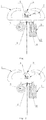
Fig. 1 is a schematic structural diagram of a position-indicating buoy before its arrangement; -
Fig. 2 is a schematic structural diagram of the position-indicating buoy during its arrangement; -
Fig. 3 is a schematic structural diagram of the position-indicating buoy after its arrangement; -
Fig. 4 is a schematic structural diagram of a sealing device before its opening; and -
Fig. 5 is a schematic structural diagram of the sealing device after its opening,
in which:- 1: gasbag;
- 2: lampstand;
- 3: position-indicating lamp;
- 4: energy storage battery;
- 5: rope;
- 6: high-pressure gas storage device;
- 7: exhaust valve;
- 8: connector;
- 9: locking ring;
- 10: fracture zone;
- 11: opening;
- 12: sealing device;
- 13: stopping spacer;
- 14: deforming spacer; and
- 15: baffle plate.
- An automatically arranged emergency shipwreck position-indicating buoy, which is arranged on a ship, comprises a gasbag, a rope, a high-pressure gas storage device, and a position-indicating light assembly; the rope has a certain length, and a rear end of the rope is wound onto a shaft arranged on the gasbag and a front end of the rope is arranged on a ship; a gas outlet of the high-pressure gas storage device is communicated with a gas inlet of the gasbag, and a sealing device is arranged at the gas outlet of the high-pressure gas storage device to avoid, in normal situations, a leakage of high-pressure gas from the high-pressure gas storage device, the sealing device is connected to the rope by a connector so as to be connected to the ship. The position-indicating light assembly is arranged above the gasbag.
- The expression "the rope has a certain length" means that the rope is required to have a certain length, and the certain length is determined by a general depth of waters in which the ship travels. A long length of the rope is needed for deep waters while a short length of the rope is needed for shallow waters to ensure that the gasbag can float on the water after the ship sinks.
- Preferably, the sealing device is connected to a locking ring, and the front end of the rope is passed through the locking ring and then connected to the ship. Specifically, the sealing device is connected to the locking ring by the connector.
- As an implementation, as the sealing device, for example, a conventional sealing device used in inflatable life rafts may be used. After the connector is triggered, the connector pulls the sealing device and the sealing device is thus opened, so that gas in the high-pressure gas storage device enters the gasbag. Furthermore, since the connector is arranged on the ship, the connector is then separated from the sealing device.
- As a second implementation, as the sealing device, for example, a high-pressure tank valve structure may be used. In this case, the connector toggles the valve and the sealing device is thus opened. Then, the connector is separated from the valve.
- As a third implementation, the sealing device comprises a baffle plate, a stopping spacer and deforming spacers; the baffle plate is extended from an opening of the high-pressure gas storage device to be connected to the connector, and the baffle plate is fitted with the opening; the stopping spacer is arranged at a front end of the baffle plate and the deforming spacers are respectively arranged on two sides of the baffle plate.
- The stopping spacer is made of material which is harder than that of the deforming spacers. This can prevent the baffle plate from separating from the opening and further avoid the leakage of gas or backward flow of water. Therefore, it may be designed that the stopping spacer has a width greater than that of the opening, and/or has a thickness greater than a height of the opening. The deforming spacers may be made of rubber or material which is fragile under a pulling force. In this way, the deforming spacers will deform under force, so that part or all of the deforming spacers will be separated from the baffle plate, or the deforming spacers will get broken.
- Further, a fracture zone is arranged between the baffle plate and the connector, and the fracture zone can withstand the pulling force during deformation of the deforming spacers, but can not withstand a stopping force exerted onto the baffle plate by the stopping spacer. When the fracture zone is subjected to the pulling force from the connector, the baffle plate can be pulled to move outward so that the sealing device opens. When the baffle plate is pulled continuously and the movement of the baffle plate is stopped by the stopping spacer, the fracture zone automatically breaks due to excessive force, so that the connector is separated from the baffle plate and the baffle plate remains in the opening of the high-pressure gas storage device. In this way, the opening is prevented from being exposed to water or gas to result in the leakage of gas or the backward flow of an external medium.
- Further, a sealing member, for example, a sealing ring, is arranged between the baffle plate and the opening, by which the backward flow of water into the high-pressure gas storage device or the leakage of gas from the high-pressure gas storage device can be better avoided.
- Preferably, the position-indicating lamp assembly comprises a lampstand, a position-indicating lamp arranged above the lampstand and an energy storage battery, and the energy storage battery is connected to the position-indicating lamp.
- Preferably, the energy storage battery is a solar energy storage battery.
- Preferably, a cross-section of the gasbag after being inflated is a trapezoid, and the position-indicating lamp assembly is arranged on an upper end surface of the trapezoid, and the rope and the high-pressure gas storage device are arranged on a lower end surface of the trapezoid. An area of the lower end surface of the gasbag is greater than that of the upper end surface.
- Preferably, the rope is provided with a scale and a value of the scale where the rope is connected to the ship is 0. The rope can measure a distance between the gasbag and the ship, i.e., the shipwreck depth.
- Preferably, the shaft on which the rope is wound is a revolving shaft, and the revolving shaft has a revolving force less than a buoyancy of the gasbag. Therefore, when the rope is not used, the rope can be well wound on the revolving shaft, and when the rope is used, the rope is unwound with a relative rising movement of the gasbag.
- Further, the automatically arranged emergency shipwreck position-indicating buoys may be used in pairs, comprising a bow position-indicating buoy and a stern position-indicating buoy. The position-indicating lamps respectively on the bow position-indicating buoy and on the stern position-indicating buoy are different in color, and the gasbags respectively on the bow position-indicating buoy and on the stern position-indicating buoy are also different in color. The use of position-indicating lamps (buoy indicators) of different colors on the bow position-indicating buoy and the stern position-indicating buoy can indicate the rough positions of a fore part and a aft part of the ship, so that operators can determine the positions of the bow and the stern according to the colors of the position-indicating lamps (buoy indicators).
- Further, an exhaust valve, which can be connected with an exhaust pump, is arranged on the gasbag. It is convenient for exhaustion and recovery of gas after use (or safety inspection test).
- The principle of the present application is described below. When a ship sinks, one end of the rope is pulled downward, and the locking ring is pulled by the rope. Due to the heavy weight of the ship, a huge pulling force drives the locking ring to pull the connector. Therefore, the sealing device of the high-pressure gas storage device is opened, and high-pressure gas enters the gasbag from the gas outlet quickly. Thus, the gasbag is inflated and then floats on the water. A circuit between the position-indicating lamp and the energy storage battery is turned on, and the position-indicating lamp lights. Therefore, the position of the shipwreck can be determined according to the position-indicating lamp (or buoy).
- To facilitate the understanding of the technical solutions of the present application, the present application will be explained in detail below by embodiments. However, the protection scope of the present application is not limited to the solutions described in the embodiments, and any combination of other feasible technical solutions is also possible in the present application.
- As shown in
Figs. 1-3 , an automatically arranged shipwreck position-indicating buoy which is arranged on a ship comprises agasbag 1, arope 5, a high-pressuregas storage device 6, and a position-indicating lamp assembly. Therope 5 has a certain length and is wound onto a shaft arranged on the gasbag. A gas outlet of the high-pressuregas storage device 6 is communicated with a gas inlet of thegasbag 1. A sealingdevice 12 is arranged at the gas outlet of the high-pressuregas storage device 6 and is connected to alocking ring 9 from which a front end of therope 5 is passed. The high-pressuregas storage device 6 and therope 5 are arranged below the gasbag, and the position-indicating lamp assembly is arranged above thegasbag 1. Anexhaust valve 7 is arranged on thegasbag 1. - An overall density of the automatically arranged shipwreck position-indicating buoy is less than that of water, so that it can be arranged by means of buoyancy.
- The position-indicating lamp assembly comprises a
lampstand 2, a position-indicatinglamp 3 arranged above thelampstand 2, and anenergy storage battery 4 which is connected to the position-indicatinglamp 3 to provide energy to the position-indicatinglamp 3. To ensure that the position-indicatinglamp 3 can light in a long period of time, a solar energy storage battery can be used as theenergy storage battery 4. - A cross-section of the gasbag after being inflated is a trapezoid. The position-indicating lamp assembly is arranged on an upper end surface of the trapezoid, and the
rope 5 and the high-pressuregas storage device 6 are arranged on a lower end surface of the trapezoid. An area of the lower end surface of the gasbag is greater than that of the upper end surface. Compared with a square structure, the trapezoidal structure provides more stable floating effect. - The automatically arranged emergency shipwreck position-indicating buoys may be used in pairs, comprising a bow position-indicating buoy arranged on a bow and a stern position-indicating buoy arranged on a stern, the structures of which are the same. The position-indicating
lamps 3 respectively on the bow position-indicating buoy and on the stern position-indicating buoy are different in color, and the gasbags respectively on the bow position-indicating buoy and on the stern position-indicating buoy are also different in color. In this way, the positions of the bow and the stern can be distinguished in the day time and at night. For example, the bow position-indicating buoy may be set in red, and the stern position-indicating buoy may be set in green, for the purpose of distinguishing them. Of course, other different colors may be used as long as the distinguishing effect can be realized. - The
rope 5 is a high-strength anticorrosive rope. Therope 5 is provided with a scale on the rope body, and a value of the scale where the rope is connected to the ship is 0. A value of the scale where the rope is wound on the tail end of the shaft is a maximum value of the scale on the rope body. The length of therope 5 may be chosen as needed, as long as a conventional traveling depth can be measured. For an extreme case where a ship sinks down to hundreds of meters of water, generally, it is not considered in the present application since this shipwreck will not result in the risk of secondary collision for passing ships and it is difficult to refloat the shipwreck. Actually, if it is possible to use the present buoy, the present application can be also recommended. - When a ship sinks, the ship drags one end of the
rope 5 to sink together. The dragging on therope 5 exerts a huge pulling force onto thelocking ring 9, so that thelocking ring 9 moves laterally relative to the opening of the high-pressuregas storage device 6, the gas outlet is opened, and the high-pressure gas enters thegasbag 1. Meanwhile, therope 5 also drags down an insulating spacer connected to a switch between the position-indicatinglamp 3 and theenergy storage battery 4, so that the circuit between theenergy storage battery 4 and the position-indicatinglamp 3 is turned on, and the position-indicatinglamp 3 lights. - The inflated gasbag has greater buoyancy and will float on the water instead of sinking together with the ship. The value of scale on the
rope 5 above the surface of water indicates the depth of the shipwreck. The rescuers determine the position of the shipwreck according to the indication of the shipwreck position-indicating buoy (position-indicating lamps 3) to start the rescue, shipwreck disposal and other operations. - At end of the shipwreck disposal, after the traditional shipwreck position-indicating buoys are arranged, the
exhaust valve 7 is connected to an exhaust pump to exhaust gas from thegasbag 1. Then, the gasbag is recovered. - To simplify the structure of the automatically arranged emergency shipwreck position-indicating system, only one position-indicating buoy can be arranged on the ship and can be arranged on the bow or on the stern or another proper position. Such a structure is simple. However, it has a disadvantage that only a rough position of the shipwreck can be indicated, and the positions of the bow and the stern cannot be accurately indicated.
- Based on
Embodiment Figs. 4 and 5 are top views of the sealing device ofFig. 1 . In those drawings, only the arrangement of the sealingdevice 12 in the high-pressuregas storage device 6 and its connection to theconnector 8 are shown, and other components are omitted. Furthermore, for ease of understanding the working principle and structure of the sealingdevice 12, an edge of the sealing device and a wall of the high-pressure gas storage device are shown to be separated from each other (they are indicated by the two circles inFigs. 4 and 5 , wherein a circumference of an inner circle represents the edge of the sealing device and a circumference of an outer circle represents the wall of the high-pressure gas storage device). Actually, the edge of the sealing device and the wall of the high-pressure gas storage device are closely fitted. Before the sealingdevice 12 is opened, no leakage of high-pressure gas happens. - The sealing
device 12 in this embodiment comprises abaffle plate 15. Thebaffle plate 15 is extended from the opening 11 of the high-pressure gas storage device to be connected to theconnector 8, and a sealing ring (not shown) is arranged between thebaffle plate 15 and the opening 11. A stoppingspacer 13 is arranged at a front end of the baffle plate and deformingspacers 14 are respectively arranged on two sides of the baffle plate. Both the stoppingspacer 13 and the deformingspacers 14 are fitted with the wall of the high-pressure gas storage device. Afracture zone 10 is arranged between thebaffle plate 15 and theconnector 8. - The working principle of
Embodiment 3 is described below. When a ship sinks, the ship pulls one end of therope 5 to move downward. Therope 5 pulls thelocking ring 9, thelocking ring 9 further pulls theconnector 8, and theconnector 8 pulls thebaffle plate 15. The sealingdevice 12 moves toward the opening 11 of the high-pressure gas storage device because of the pulling of thebaffle plate 15. The sealingdevice 12 is opened (as shown inFig. 5 ), and the high-pressure gas enters thegasbag 1 from the gas outlet. A further movement of thebaffle plate 15 toward the opening 11 is limited by the stoppingspacer 13. When the pulling force increases continuously, thefracture zone 10 between theconnector 8 and thebaffle plate 15 gets broken. Now, the floatinggasbag 1 is restricted only by therope 5. - The above embodiments are merely preferred implementations of the present application and not intended to limit the scope of the present application. Various transformations and improvements made to the technical solutions of the present application by a person having ordinary skills in the art shall fall into the protection scope defined by the claims of the present application. Meanwhile, the numerical references as used in the present application are merely provided to help a person having ordinary skills in the art to understand the technical solutions of the present application, and have no any limitation to the protection scope of the present application.
Claims (10)
- An automatically arranged emergency shipwreck position-indicating buoy comprising: a gasbag (1), a rope (5), a high-pressure gas storage device (6), and a position-indicating light assembly; the rope (5) has a certain length, and a rear end of the rope is wound onto a shaft arranged on the gasbag (1) and a front end of the rope is arranged on a ship; a gas outlet of the high-pressure gas storage device is communicated with a gas inlet of the gasbag, and a sealing device (12) is arranged at the gas outlet of the high-pressure gas storage device, the sealing device (12) is connected to the rope (5) by a connector (8) so as to be connected to the ship; the position-indicating light assembly is arranged above the gasbag (1).
- The automatically arranged emergency shipwreck position-indicating buoy according to claim 1, wherein the sealing device (12) is connected to a locking ring (9) by the connector (8), and the front end of the rope is passed through the locking ring (9) and then connected to the ship.
- The automatically arranged emergency shipwreck position-indicating buoy according to claim 1 or 2, wherein the sealing device (12) comprises a baffle plate (15), a stopping spacer (13) and deforming spacers (14); the baffle plate (15) is extended from an opening (11) of the high-pressure gas storage device to be connected to the connector (8), and the baffle plate (15) is fitted with the opening (11); the stopping spacer (13) is arranged at a front end of the baffle plate and the deforming spacers (14) are respectively arranged on two sides of the baffle plate.
- The automatically arranged emergency shipwreck position-indicating buoy according to claim 3, wherein a fracture zone (10) is arranged between the baffle plate (15) and the connector (8), and the fracture zone (10) can withstand a pulling force during deformation of the deforming spacers (14), but can not withstand a stopping force exerted onto the baffle plate (15) by the stopping spacer (13).
- The automatically arranged emergency shipwreck position-indicating buoy according to any one of claims 1, 2 or 4, wherein the position-indicating lamp assembly comprises a lampstand (2), a position-indicating lamp (3) arranged above the lampstand and an energy storage battery (4), the energy storage battery 4 is connected to the position-indicating lamp (3).
- The automatically arranged emergency shipwreck position-indicating buoy according to any one of claims 1, 2 or 4, wherein a cross-section of the gasbag after being inflated is a trapezoid, and the position-indicating lamp assembly is arranged on an upper end surface of the trapezoid, and the rope (5) and the high-pressure gas storage device (6) are arranged on a lower end surface of the trapezoid.
- The automatically arranged emergency shipwreck position-indicating buoy according to any one of claims 1, 2 or 4, wherein the rope (5) is provided with a scale and a value of the scale where the rope is connected to the ship is 0.
- The automatically arranged emergency shipwreck position-indicating buoy according to any one of claims 1, 2 or 4, wherein the shaft on which the rope (5) is wound is a revolving shaft, and the revolving shaft has a revolving force less than a buoyancy of the gasbag (1).
- The automatically arranged emergency shipwreck position-indicating buoy according to any one of claims 1, 2 or 4, wherein an exhaust valve (7) is arranged on the gasbag (1).
- The automatically arranged emergency shipwreck position-indicating buoy according to any one of claims 1, 2 or 4, wherein the buoys are used in pairs, comprising a bow position-indicating buoy and a stern position-indicating buoy; the position-indicating lamps (3) respectively on the bow position-indicating buoy and on the stern position-indicating buoy are different in color, and the gasbags (1) respectively on the bow position-indicating buoy and on the stern position-indicating buoy are also different in color.
Applications Claiming Priority (2)
| Application Number | Priority Date | Filing Date | Title |
|---|---|---|---|
| CN201520950980.1U CN205221033U (en) | 2015-11-25 | 2015-11-25 | Automatic lay emergent sunken ship and show temperature scale |
| PCT/CN2016/106716 WO2017088726A1 (en) | 2015-11-25 | 2016-11-22 | Automatically-arranged emergency wreck position-indicating buoy |
Publications (3)
| Publication Number | Publication Date |
|---|---|
| EP3366569A1 EP3366569A1 (en) | 2018-08-29 |
| EP3366569A4 EP3366569A4 (en) | 2018-10-24 |
| EP3366569B1 true EP3366569B1 (en) | 2019-06-19 |
Family
ID=55896115
Family Applications (1)
| Application Number | Title | Priority Date | Filing Date |
|---|---|---|---|
| EP16867949.6A Active EP3366569B1 (en) | 2015-11-25 | 2016-11-22 | Automatically-arranged emergency wreck position-indicating buoy |
Country Status (4)
| Country | Link |
|---|---|
| US (1) | US10239595B2 (en) |
| EP (1) | EP3366569B1 (en) |
| CN (1) | CN205221033U (en) |
| WO (1) | WO2017088726A1 (en) |
Families Citing this family (5)
| Publication number | Priority date | Publication date | Assignee | Title |
|---|---|---|---|---|
| CN205221033U (en) | 2015-11-25 | 2016-05-11 | 杨庆勇 | Automatic lay emergent sunken ship and show temperature scale |
| CN106056976B (en) * | 2016-08-05 | 2018-10-02 | 北京金盾麟瑞通信科技有限公司石家庄分公司 | Ship positioning navigation and safe early warning alarm system |
| CN109572961A (en) * | 2019-01-22 | 2019-04-05 | 大连海洋大学 | It is a kind of wirelessly to give instructions by telegraph a device |
| CN112255656A (en) * | 2020-08-24 | 2021-01-22 | 江苏中智腾飞信息科技有限公司 | Beidou navigation and communication equipment with emergency position indicator function |
| CN114313133B (en) * | 2021-12-30 | 2024-08-27 | 宁波军鸽防务科技有限公司 | Sinking equipment position indicating mark |
Family Cites Families (17)
| Publication number | Priority date | Publication date | Assignee | Title |
|---|---|---|---|---|
| US3123842A (en) * | 1964-03-10 | Gas ejected apparatus for locating | ||
| US2830309A (en) * | 1955-02-10 | 1958-04-15 | Harvel T Lawson | Swimmer's marker buoy |
| US3341871A (en) * | 1965-10-04 | 1967-09-19 | Universal Oil Prod Co | Flotation gear for the recovery of a submerged craft |
| US3618150A (en) * | 1969-03-04 | 1971-11-09 | James V Anselmi | Beacon buoy marker containing lifesaving and signaling devices |
| GB1280312A (en) * | 1969-04-25 | 1972-07-05 | James Basset | Method and means for refloating sunken objects such as craft and buoys, and craft and buoys incorporating such means |
| FR2447729A1 (en) * | 1979-01-30 | 1980-08-29 | Chotard Patrick | Personal distress signalling equipment - comprises gas-filled balloon with mooring wire and inflated instantly |
| US4721486A (en) * | 1986-08-08 | 1988-01-26 | Goettel Robert J | Automatic marker buoy release mechanism |
| US4784626A (en) * | 1987-05-11 | 1988-11-15 | Delaro Paul J | Sunken vessel locator buoy |
| US6032607A (en) * | 1997-04-08 | 2000-03-07 | Ashline; Clifford E. | Emergency location signaling device |
| DK200201187A (en) * | 2002-08-07 | 2004-02-08 | Hvalpsund Vodbinderi As | Plant, location unit and method for locating equipment used in water |
| KR100509182B1 (en) * | 2003-07-28 | 2005-08-22 | 송유천 | An equipment confirming final position and slaving of sunken vessel |
| KR20040027306A (en) * | 2003-08-14 | 2004-04-01 | 김명각 | A verify device sunken ship location |
| KR20100096767A (en) * | 2009-02-25 | 2010-09-02 | 강원도립대학산학협력단 | Submersed position directing apparatus of a submarine robot |
| KR101258643B1 (en) | 2010-04-21 | 2013-04-26 | 이장수 | Apparatus for transmitting distress signal for ship |
| CN102514695A (en) * | 2011-09-02 | 2012-06-27 | 海南新博海通科技有限公司 | Emergent wireless distress positioning system for fishing vessel |
| CN103950521B (en) * | 2014-05-07 | 2017-02-08 | 交通运输部水运科学研究所 | Detection locating device for looking for container falling into water and detection method thereof |
| CN205221033U (en) * | 2015-11-25 | 2016-05-11 | 杨庆勇 | Automatic lay emergent sunken ship and show temperature scale |
-
2015
- 2015-11-25 CN CN201520950980.1U patent/CN205221033U/en not_active Expired - Lifetime
-
2016
- 2016-11-22 US US15/779,078 patent/US10239595B2/en active Active
- 2016-11-22 WO PCT/CN2016/106716 patent/WO2017088726A1/en not_active Ceased
- 2016-11-22 EP EP16867949.6A patent/EP3366569B1/en active Active
Non-Patent Citations (1)
| Title |
|---|
| None * |
Also Published As
| Publication number | Publication date |
|---|---|
| EP3366569A4 (en) | 2018-10-24 |
| CN205221033U (en) | 2016-05-11 |
| EP3366569A1 (en) | 2018-08-29 |
| WO2017088726A1 (en) | 2017-06-01 |
| US20180354595A1 (en) | 2018-12-13 |
| US10239595B2 (en) | 2019-03-26 |
Similar Documents
| Publication | Publication Date | Title |
|---|---|---|
| US10239595B2 (en) | Automatically arranged emergency shipwreck position-indicating buoy | |
| CN105555655B (en) | self-propelled ship | |
| KR101740139B1 (en) | Auto Releasing New Danger Mark Buoy | |
| CN205293021U (en) | Emergent AIS of boats and ships shows temperature scale | |
| CN110494354B (en) | Automatic disengaging danger marking buoy | |
| CN103459249A (en) | System for evacuating people from capsized ships | |
| CN104085515A (en) | Salvage device and salvage method | |
| CN107499471A (en) | A kind of passenger boat emergency escape system | |
| US4033002A (en) | Life saving equipment for vessels | |
| CN106800077A (en) | Ship inclines automatic emergency sink preventing apparatus | |
| CN103112558A (en) | Emergency self-help ship for sailing in danger | |
| CN201566615U (en) | small rescue hovercraft | |
| CN111874184A (en) | Anti-loss device for ocean equipment | |
| CN110466695B (en) | A drowning container positioning and floating device | |
| CN108438170A (en) | Emergency position indicating radio beacon device with mark shipwreck real-time azimuthal function | |
| CN204056260U (en) | A kind of sea rescue carrier | |
| KR20110122929A (en) | Here i am | |
| JPH0885492A (en) | Marker buoy device for submersible buoy | |
| WO2022134389A1 (en) | Marine vessel emergency navigation position indicating search and rescue and environment monitoring anti-pollution integrated smart platform | |
| CN204926087U (en) | An Intelligent Assessment System for Ship Safety Based on ECDIS | |
| KR20220007926A (en) | A device that identifies the location of a sunken ship | |
| CN208306955U (en) | Emergency position indicating radio beacon device with mark shipwreck real-time azimuthal function | |
| CN114684334A (en) | Ship emergency navigation position-indicating search and rescue and environment monitoring anti-pollution integrated intelligent platform | |
| CN203558190U (en) | Dredging construction safety warning buoy | |
| CN205801461U (en) | A kind of wreck marking device peculiar to vessel |
Legal Events
| Date | Code | Title | Description |
|---|---|---|---|
| STAA | Information on the status of an ep patent application or granted ep patent |
Free format text: STATUS: THE INTERNATIONAL PUBLICATION HAS BEEN MADE |
|
| PUAI | Public reference made under article 153(3) epc to a published international application that has entered the european phase |
Free format text: ORIGINAL CODE: 0009012 |
|
| STAA | Information on the status of an ep patent application or granted ep patent |
Free format text: STATUS: REQUEST FOR EXAMINATION WAS MADE |
|
| 17P | Request for examination filed |
Effective date: 20180523 |
|
| AK | Designated contracting states |
Kind code of ref document: A1 Designated state(s): AL AT BE BG CH CY CZ DE DK EE ES FI FR GB GR HR HU IE IS IT LI LT LU LV MC MK MT NL NO PL PT RO RS SE SI SK SM TR |
|
| AX | Request for extension of the european patent |
Extension state: BA ME |
|
| A4 | Supplementary search report drawn up and despatched |
Effective date: 20180926 |
|
| RIC1 | Information provided on ipc code assigned before grant |
Ipc: B63C 7/26 20060101AFI20180920BHEP |
|
| GRAP | Despatch of communication of intention to grant a patent |
Free format text: ORIGINAL CODE: EPIDOSNIGR1 |
|
| STAA | Information on the status of an ep patent application or granted ep patent |
Free format text: STATUS: GRANT OF PATENT IS INTENDED |
|
| DAV | Request for validation of the european patent (deleted) | ||
| DAX | Request for extension of the european patent (deleted) | ||
| INTG | Intention to grant announced |
Effective date: 20190118 |
|
| GRAS | Grant fee paid |
Free format text: ORIGINAL CODE: EPIDOSNIGR3 |
|
| GRAA | (expected) grant |
Free format text: ORIGINAL CODE: 0009210 |
|
| STAA | Information on the status of an ep patent application or granted ep patent |
Free format text: STATUS: THE PATENT HAS BEEN GRANTED |
|
| AK | Designated contracting states |
Kind code of ref document: B1 Designated state(s): AL AT BE BG CH CY CZ DE DK EE ES FI FR GB GR HR HU IE IS IT LI LT LU LV MC MK MT NL NO PL PT RO RS SE SI SK SM TR |
|
| REG | Reference to a national code |
Ref country code: GB Ref legal event code: FG4D |
|
| REG | Reference to a national code |
Ref country code: CH Ref legal event code: EP |
|
| REG | Reference to a national code |
Ref country code: IE Ref legal event code: FG4D |
|
| REG | Reference to a national code |
Ref country code: AT Ref legal event code: REF Ref document number: 1145173 Country of ref document: AT Kind code of ref document: T Effective date: 20190715 |
|
| REG | Reference to a national code |
Ref country code: DE Ref legal event code: R096 Ref document number: 602016015743 Country of ref document: DE |
|
| REG | Reference to a national code |
Ref country code: NO Ref legal event code: T2 Effective date: 20190619 |
|
| REG | Reference to a national code |
Ref country code: NL Ref legal event code: MP Effective date: 20190619 |
|
| PG25 | Lapsed in a contracting state [announced via postgrant information from national office to epo] |
Ref country code: AL Free format text: LAPSE BECAUSE OF FAILURE TO SUBMIT A TRANSLATION OF THE DESCRIPTION OR TO PAY THE FEE WITHIN THE PRESCRIBED TIME-LIMIT Effective date: 20190619 Ref country code: FI Free format text: LAPSE BECAUSE OF FAILURE TO SUBMIT A TRANSLATION OF THE DESCRIPTION OR TO PAY THE FEE WITHIN THE PRESCRIBED TIME-LIMIT Effective date: 20190619 Ref country code: LT Free format text: LAPSE BECAUSE OF FAILURE TO SUBMIT A TRANSLATION OF THE DESCRIPTION OR TO PAY THE FEE WITHIN THE PRESCRIBED TIME-LIMIT Effective date: 20190619 Ref country code: SE Free format text: LAPSE BECAUSE OF FAILURE TO SUBMIT A TRANSLATION OF THE DESCRIPTION OR TO PAY THE FEE WITHIN THE PRESCRIBED TIME-LIMIT Effective date: 20190619 Ref country code: HR Free format text: LAPSE BECAUSE OF FAILURE TO SUBMIT A TRANSLATION OF THE DESCRIPTION OR TO PAY THE FEE WITHIN THE PRESCRIBED TIME-LIMIT Effective date: 20190619 |
|
| REG | Reference to a national code |
Ref country code: LT Ref legal event code: MG4D |
|
| PG25 | Lapsed in a contracting state [announced via postgrant information from national office to epo] |
Ref country code: LV Free format text: LAPSE BECAUSE OF FAILURE TO SUBMIT A TRANSLATION OF THE DESCRIPTION OR TO PAY THE FEE WITHIN THE PRESCRIBED TIME-LIMIT Effective date: 20190619 Ref country code: GR Free format text: LAPSE BECAUSE OF FAILURE TO SUBMIT A TRANSLATION OF THE DESCRIPTION OR TO PAY THE FEE WITHIN THE PRESCRIBED TIME-LIMIT Effective date: 20190920 Ref country code: BG Free format text: LAPSE BECAUSE OF FAILURE TO SUBMIT A TRANSLATION OF THE DESCRIPTION OR TO PAY THE FEE WITHIN THE PRESCRIBED TIME-LIMIT Effective date: 20190919 Ref country code: RS Free format text: LAPSE BECAUSE OF FAILURE TO SUBMIT A TRANSLATION OF THE DESCRIPTION OR TO PAY THE FEE WITHIN THE PRESCRIBED TIME-LIMIT Effective date: 20190619 |
|
| REG | Reference to a national code |
Ref country code: AT Ref legal event code: MK05 Ref document number: 1145173 Country of ref document: AT Kind code of ref document: T Effective date: 20190619 |
|
| PG25 | Lapsed in a contracting state [announced via postgrant information from national office to epo] |
Ref country code: AT Free format text: LAPSE BECAUSE OF FAILURE TO SUBMIT A TRANSLATION OF THE DESCRIPTION OR TO PAY THE FEE WITHIN THE PRESCRIBED TIME-LIMIT Effective date: 20190619 Ref country code: CZ Free format text: LAPSE BECAUSE OF FAILURE TO SUBMIT A TRANSLATION OF THE DESCRIPTION OR TO PAY THE FEE WITHIN THE PRESCRIBED TIME-LIMIT Effective date: 20190619 Ref country code: RO Free format text: LAPSE BECAUSE OF FAILURE TO SUBMIT A TRANSLATION OF THE DESCRIPTION OR TO PAY THE FEE WITHIN THE PRESCRIBED TIME-LIMIT Effective date: 20190619 Ref country code: NL Free format text: LAPSE BECAUSE OF FAILURE TO SUBMIT A TRANSLATION OF THE DESCRIPTION OR TO PAY THE FEE WITHIN THE PRESCRIBED TIME-LIMIT Effective date: 20190619 Ref country code: EE Free format text: LAPSE BECAUSE OF FAILURE TO SUBMIT A TRANSLATION OF THE DESCRIPTION OR TO PAY THE FEE WITHIN THE PRESCRIBED TIME-LIMIT Effective date: 20190619 Ref country code: PT Free format text: LAPSE BECAUSE OF FAILURE TO SUBMIT A TRANSLATION OF THE DESCRIPTION OR TO PAY THE FEE WITHIN THE PRESCRIBED TIME-LIMIT Effective date: 20191021 Ref country code: SK Free format text: LAPSE BECAUSE OF FAILURE TO SUBMIT A TRANSLATION OF THE DESCRIPTION OR TO PAY THE FEE WITHIN THE PRESCRIBED TIME-LIMIT Effective date: 20190619 |
|
| PG25 | Lapsed in a contracting state [announced via postgrant information from national office to epo] |
Ref country code: ES Free format text: LAPSE BECAUSE OF FAILURE TO SUBMIT A TRANSLATION OF THE DESCRIPTION OR TO PAY THE FEE WITHIN THE PRESCRIBED TIME-LIMIT Effective date: 20190619 Ref country code: IS Free format text: LAPSE BECAUSE OF FAILURE TO SUBMIT A TRANSLATION OF THE DESCRIPTION OR TO PAY THE FEE WITHIN THE PRESCRIBED TIME-LIMIT Effective date: 20191019 Ref country code: IT Free format text: LAPSE BECAUSE OF FAILURE TO SUBMIT A TRANSLATION OF THE DESCRIPTION OR TO PAY THE FEE WITHIN THE PRESCRIBED TIME-LIMIT Effective date: 20190619 Ref country code: SM Free format text: LAPSE BECAUSE OF FAILURE TO SUBMIT A TRANSLATION OF THE DESCRIPTION OR TO PAY THE FEE WITHIN THE PRESCRIBED TIME-LIMIT Effective date: 20190619 |
|
| PG25 | Lapsed in a contracting state [announced via postgrant information from national office to epo] |
Ref country code: TR Free format text: LAPSE BECAUSE OF FAILURE TO SUBMIT A TRANSLATION OF THE DESCRIPTION OR TO PAY THE FEE WITHIN THE PRESCRIBED TIME-LIMIT Effective date: 20190619 |
|
| PG25 | Lapsed in a contracting state [announced via postgrant information from national office to epo] |
Ref country code: DK Free format text: LAPSE BECAUSE OF FAILURE TO SUBMIT A TRANSLATION OF THE DESCRIPTION OR TO PAY THE FEE WITHIN THE PRESCRIBED TIME-LIMIT Effective date: 20190619 Ref country code: PL Free format text: LAPSE BECAUSE OF FAILURE TO SUBMIT A TRANSLATION OF THE DESCRIPTION OR TO PAY THE FEE WITHIN THE PRESCRIBED TIME-LIMIT Effective date: 20190619 |
|
| PG25 | Lapsed in a contracting state [announced via postgrant information from national office to epo] |
Ref country code: IS Free format text: LAPSE BECAUSE OF FAILURE TO SUBMIT A TRANSLATION OF THE DESCRIPTION OR TO PAY THE FEE WITHIN THE PRESCRIBED TIME-LIMIT Effective date: 20200224 |
|
| REG | Reference to a national code |
Ref country code: DE Ref legal event code: R097 Ref document number: 602016015743 Country of ref document: DE |
|
| REG | Reference to a national code |
Ref country code: CH Ref legal event code: PL |
|
| PLBE | No opposition filed within time limit |
Free format text: ORIGINAL CODE: 0009261 |
|
| STAA | Information on the status of an ep patent application or granted ep patent |
Free format text: STATUS: NO OPPOSITION FILED WITHIN TIME LIMIT |
|
| PG2D | Information on lapse in contracting state deleted |
Ref country code: IS |
|
| PG25 | Lapsed in a contracting state [announced via postgrant information from national office to epo] |
Ref country code: CH Free format text: LAPSE BECAUSE OF NON-PAYMENT OF DUE FEES Effective date: 20191130 Ref country code: LI Free format text: LAPSE BECAUSE OF NON-PAYMENT OF DUE FEES Effective date: 20191130 Ref country code: MC Free format text: LAPSE BECAUSE OF FAILURE TO SUBMIT A TRANSLATION OF THE DESCRIPTION OR TO PAY THE FEE WITHIN THE PRESCRIBED TIME-LIMIT Effective date: 20190619 Ref country code: LU Free format text: LAPSE BECAUSE OF NON-PAYMENT OF DUE FEES Effective date: 20191122 |
|
| 26N | No opposition filed |
Effective date: 20200603 |
|
| REG | Reference to a national code |
Ref country code: BE Ref legal event code: MM Effective date: 20191130 |
|
| PG25 | Lapsed in a contracting state [announced via postgrant information from national office to epo] |
Ref country code: SI Free format text: LAPSE BECAUSE OF FAILURE TO SUBMIT A TRANSLATION OF THE DESCRIPTION OR TO PAY THE FEE WITHIN THE PRESCRIBED TIME-LIMIT Effective date: 20190619 |
|
| PG25 | Lapsed in a contracting state [announced via postgrant information from national office to epo] |
Ref country code: IE Free format text: LAPSE BECAUSE OF NON-PAYMENT OF DUE FEES Effective date: 20191122 |
|
| PG25 | Lapsed in a contracting state [announced via postgrant information from national office to epo] |
Ref country code: BE Free format text: LAPSE BECAUSE OF NON-PAYMENT OF DUE FEES Effective date: 20191130 |
|
| PG25 | Lapsed in a contracting state [announced via postgrant information from national office to epo] |
Ref country code: CY Free format text: LAPSE BECAUSE OF FAILURE TO SUBMIT A TRANSLATION OF THE DESCRIPTION OR TO PAY THE FEE WITHIN THE PRESCRIBED TIME-LIMIT Effective date: 20190619 |
|
| PG25 | Lapsed in a contracting state [announced via postgrant information from national office to epo] |
Ref country code: HU Free format text: LAPSE BECAUSE OF FAILURE TO SUBMIT A TRANSLATION OF THE DESCRIPTION OR TO PAY THE FEE WITHIN THE PRESCRIBED TIME-LIMIT; INVALID AB INITIO Effective date: 20161122 Ref country code: MT Free format text: LAPSE BECAUSE OF FAILURE TO SUBMIT A TRANSLATION OF THE DESCRIPTION OR TO PAY THE FEE WITHIN THE PRESCRIBED TIME-LIMIT Effective date: 20190619 |
|
| PG25 | Lapsed in a contracting state [announced via postgrant information from national office to epo] |
Ref country code: MK Free format text: LAPSE BECAUSE OF FAILURE TO SUBMIT A TRANSLATION OF THE DESCRIPTION OR TO PAY THE FEE WITHIN THE PRESCRIBED TIME-LIMIT Effective date: 20190619 |
|
| PGFP | Annual fee paid to national office [announced via postgrant information from national office to epo] |
Ref country code: DE Payment date: 20251117 Year of fee payment: 10 |
|
| PGFP | Annual fee paid to national office [announced via postgrant information from national office to epo] |
Ref country code: GB Payment date: 20251126 Year of fee payment: 10 |
|
| PGFP | Annual fee paid to national office [announced via postgrant information from national office to epo] |
Ref country code: NO Payment date: 20251028 Year of fee payment: 10 |
|
| PGFP | Annual fee paid to national office [announced via postgrant information from national office to epo] |
Ref country code: FR Payment date: 20251127 Year of fee payment: 10 |